


FACSIMILE EQUIPMENT
SERVICE MANUAL
MODEL: MFC5100C/MFC590

© Copyright Brother 2001
All rights reserved.
No part of this publication may be reproduc ed in any
form or by any means without perm ission in writing
from the publisher.
Specifications are subject to change without notice.

PREFACE
This publication is a Service Manual covering the specifications, construction, theory of operation,
and maintenance of the Brother facsimile equipment. It includes information required for field
troubleshooting and repair--disassembly, reassembly, and lubrication--so that service personnel
will be able to understand equipment function, to rapidly repair the equipment and order any
necessary spare parts.
To perform appropriate maintenance so that the facsimile equipment is always in best condition
for the customer, the service personnel must adequately understand and apply this manual.
This manual is made up of six chapters and appendices.
CHAPTER 1 GENERAL DESCRIPTION
CHAPTER 2 INSTALLATION
CHAPTER 3 THEORY OF OPERATION
CHAPTER 4 DISASSEMBLY/REASSEMBLY AND LUBRICATION
CHAPTER 5 MAINTENANCE MODE
CHAPTER 6 ERROR INDICATION AND TROUBLESHOOTING
Appendix 1. EEPROM Customizing Codes
Appendix 2. Firmware Switches (WSW)
Appendix 3. Circuit Diagrams
This manual describes the models and their versions to be destined for major countries. The specifications
and functions are subject to change depending upon each destination.

CHAPTER
GENERAL DESCRIPTION
1

CHAPTER 1 GENERAL DESCRIPTION
CONTENTS
1.1 EQUIPMENT OUTLINE ...................................................................................................1-1
1.1.1 External Appearance and Weight ........................................................................1-1
1.1.2 Components.........................................................................................................1-1
1.2 SPECIFICATIONS............................................................................................................1-2
1.1 EQUIPMENT OUTLINE
1.1.1 External Appearance and Weight
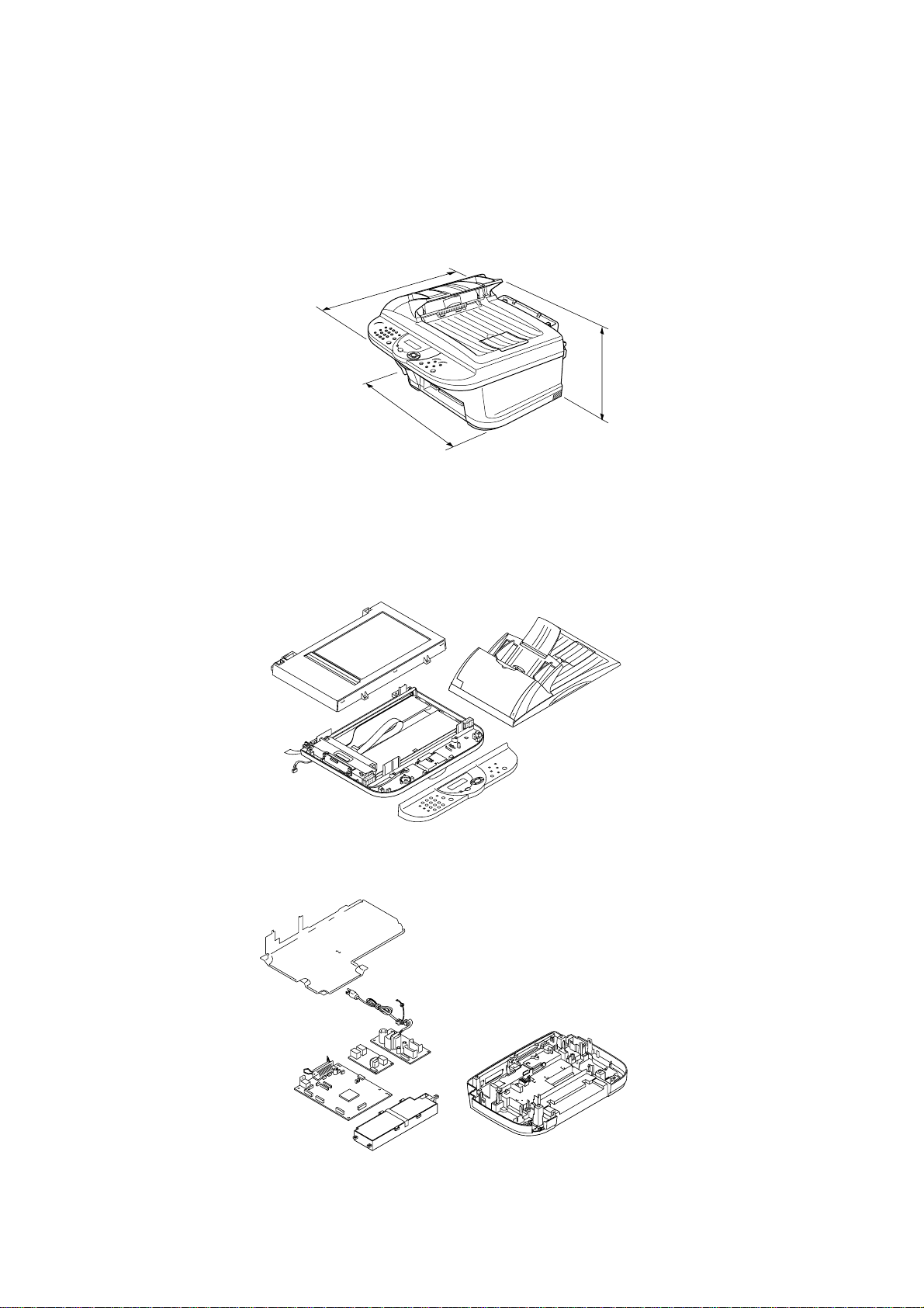
The figure below shows the equipment appearance and approximate dimensions.
Weight: Machine proper Approx. 15 kg (33.1 lbs.)
In package Approx. 11 kg (24.2 lbs.)
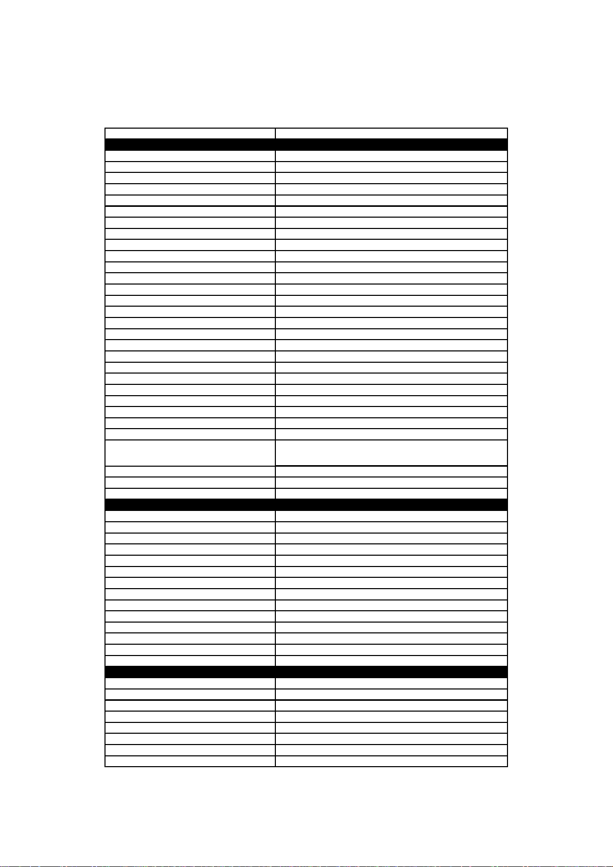
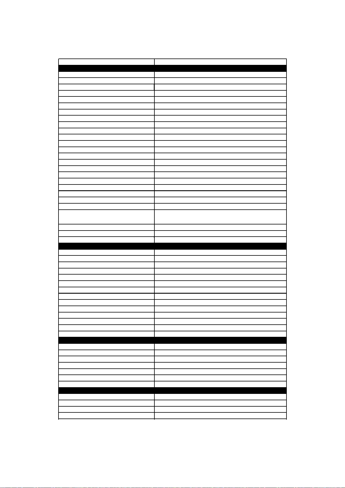
1.1.2 Components
The equipment consists of the following major components:
1-1
1.2 SPECIFICATIONS
Model Name MFC-5100C
GENERAL
Print Engine Ink Jet (BH 2-head)
Modem Speed (bps) 14,400 (Fax)
Transmission Speed (sec.) 6 (Brother#1, MMR)
ITU-T Group G3
Coding System MH/MR/MMR/JPEG
Print Paper Size (W x L) 3.5"-8.5" x 5.0"-14"
Document Size for ADF (W x L) 5.8"-8.5" x 5.7"-14"
Max. Document Size for Flat-bed Scan (W x L) 8.5" x 11.7"
Print Paper Margin (upper, lower, left, right) 0.12, 0.43, 0.12, 0.12 inch (3, 11, 3, 3 mm)
ADF (pages) Up to 30
LCD Columns 16 characters
LCD Lines 1 line
LCD Bac klight No
Backup Clock Yes (1 hour)
Memory Backup N/A
Memory Capacity (physical) 4MB (RAM)
Optional Memory No
Dimension s w/ Carton (WxDxH)
Dimensions w/o Carton (WxDxH) 18.4"x18.4"x14.6" (468x467x370 mm)
Weight w/ Carton 33.1 lbs/15 kg
Weight w/o Carton 24.2 lbs/ 11 kg
Color Gray 1495
Standby Mode No
PC-Fax Protocol Compliance N/A
Simultaneous Operation Yes (Print/Fax, Print/Scan)
Energy Star Compliant Yes
Operating Environment Temperature
Humidity
Power Source 120 VAC, 50/60 Hz
Power Consumption (Standby/Peak) Under 13.5W/40W
On/Off Switch No
TELEPHONE
Handset No
One-Touch Dial 0
Speed Dial Max. 40
Speaker Phone No
Chain Dialing Yes
Caller ID No
Call Waiting Caller ID No
Distinctive Ringing Yes
Hold/Mut e Key No
Hook Key No
Power Failure Dialing No
Speaker Volume No
Ring Volume Yes (2 steps + OFF)
Handset Volume No
FAX
Scan Speed (A4:Standard) Approx. 3 sec./page (A4: standard)
Memory Transmission (Brother#1 Chart) Yes (200:MMR)
Memory Transmission (ITU-T Chart) Yes (170:MMR)
Out-of-Paper Reception (Brother #1 Chart) Yes (200:MMR)
Out-of-Paper Reception (ITU-T Chart) Yes (170:MMR)
Color FAX (Document Send/Receive) Yes/Yes
Color FAX (Memory Send/Receive) No/Yes
(1/2)
23.3"x22.3"x18.1" (592x566x460 mm)
10 - 35 degrees Centigrade
20% to 80%
1-2

Model Name MFC-5100C
INTERFACE
External TAD Interface Yes
Host Interface (IEEE1284)
Host Interface (USB)
LAN Interface
PRINTER
Color/Mono Color/Mono
Engine Type Piezo Ink Jet (2-head BH: 75 nozzles/color)
Resolution (dpi) 1200x1200 /2400x1200 (Mono/Color)
10/8 (Mono/Color: 600*150)
Speed (ppm)
Paper Capacity (sheets) 100
Output Paper Capacity (sheets) 50
Standard Print Language Windows GDI
Emulation No
Resident Fonts Yes
Fonts Disk Based Yes
Paper Handling Size
Manual Feed Slot N/A
Other Paper Type OHP, Envelopes
Sheet Weight (Paper Cassette)
(Manual Slot)
Printer Driver
COPY
Color/Mono Color/Mono
Speed (ppm) 7/4 (Mono/Color)
Multi Copy (Stack) Yes (Color) or Via PC
Multi Copy (Sort) Yes (Color) or Via PC
Resolution (dpi) Max. 1200x1200 (color)
SCANNER
Color/Mono Color/Mono
Resolution (dpi) (Physical) CCD: 600x2400 (Opt.)
Resolution (dpi) (Logical) 9600 (Int.)
Speed (ppm) Max. 3 sec
Gray Scale 256
TWAIN Compliant&Operati ng System
PCI Scanner (Parallel/Serial)
Color Depth 36-bit color processing (24-bit external)
ACCESSORIES
Cartridge 4 colors (each separate tank)
Life / Yield (Draft, 5% Coverage) BK: 950, CL: 450
4/3.5 (Mono/Color: 600*300)
2/1.5 (Mono/Color: 600*600)
0.2/0.2 (Mono/Color: 1200*1200/2400*1200)
LTR, LGL, A4, B5, A5, EXE,
Post card, Photo, Index card
64-120 g/m2 (17 - 32 lb)
Win95/98/98SE/Me/2000Professinal/NT4.0/
Win95/98/98SE/2000Professinal/NT4.0/Me
Yes
Yes
No
N/A
MacOS 8.5-9.1
MacOS 8.6-/9.1
Parallel/ USB
(2/2)
1-3
Model Name MFC-590
GENERAL
Print Engine Ink Jet (BH 2-head)
Modem Speed (bps) 14,400 (Fax)
Transmission Speed (sec.) 6 (Brother#1, MMR )
ITU-T Group G3
Coding System MH/MR/MMR/JPEG
Print Paper Size (W x L) 90-216 x 127-216 mm
Document Size for ADF (W x L) 147-216 x 145-356 mm
Max. Document Size for Flat-bed Scan (W x L) 216 x 297 mm
Print Paper Margin (upper, lower, left, right) 0.12, 0.43, 0.12, 0.12 inch (3, 11, 3, 3 mm)
ADF (pages) Up to 30
LCD Columns 16 characters
LCD Lines 1 line
LCD Bac klight Yes
Backup Clock Yes (1 hour)
Memory Backup N/A
Memory Capacity (physical) 4 MB (Actually 8 MB)
Optional Memory No
Dimensions w/o Carton (WxDxH)
Dimensions w/ Carton (WxDxH) 18.4"x18.4"x14.6" (468x467x370 mm)
Weight w/o Carton 24.2 lbs/ 11 kg
Weight w/ Carton 33.1 lbs/15 kg
Color Gray 1495
Operating Environment Temperature
Humidity
Power Source 240 VAC, 50/60 Hz
Power Consumption (Standby/Peak) Under 13W/50W
On/Off Switch No
TELEPHONE
Handset N/A
One-Touch Dial N/A
Speed Dial Max. 100
Speaker Phone No
Chain Dialing Yes
Caller ID No
Call Waiting Caller ID No
Distinctive Ringing Yes (Only UK, Denmark)
Hold/Mute Key No
Hook Key (Tel Key) Tel (for F/T switch)
Power Failure Dialing No
Speaker Volume No
Ring Volume Yes (2 steps + OFF)
Handset Volume No
FAX
Scan Speed (A4:Standard) Approx. 3 sec./page (A4: standard)
Memory Transmission (Brother#1 Chart) Yes (200:MMR)
Memory Transmission (ITU-T Chart) Yes (170:MMR)
Out-of-Paper Reception (Brother #1 Chart) Yes (200:MMR)
Out-of-Paper Reception (ITU-T Chart) Yes (170:MMR)
Color FAX (Document Send/Receive) Yes/Yes
Color FAX (Memory Send/Receive) No/Yes
INTERFACE
External TAD Interface Yes
Host Interface (IEEE1284)
Host Interface (USB)
LAN Interface
23.3"x22.3"x18.1" (592x566x460 mm)
10 - 35 degrees Centigrade
20% to 80%
Yes
Yes
No
(1/2)
1-4
Model Name MFC-590
PRINTER
Color/Mono Color/Mono
Engine Type Piezo Ink Jet (2-head BH: 75 nozzles/color)
Resolution (dpi) 1200x1200 /2400x1200 (Mono/Color)
10/8 (Mono/Color: 600*150)
Speed (ppm)
Paper Capacity (sheets) 100
Output Paper Capacity (sheets) 50
Standard Print Language Windows GDI
Emulation N/A
Resident Fonts Yes
Fonts Disk Based Yes
Paper Handling Size
Manual Feed Slot N/A
Other Paper Type OHP, Envelopes
Sheet Weight (Paper Cassette)
(Manual Slot)
Printer Driver
COPY
Color/Mono Color/Mono
Speed (ppm) 7/4
Multi Cop y (Stack) Yes (Color) or Via PC
Multi Cop y (Sor t) Yes (Color) or Via PC
Resolution (dpi) Max. 1200x1200
SCANNER
Color/Mono Color/Mono
Resolution (dpi) (Physical) CCD 600x2400 (Opt.)
Resolution (dpi) (Logical) 9600 (Int.)
Speed (ppm) Max. 3 sec.
Gray Scale 256
TWAIN Compliant&Opera ting System
PCI Scanner (Parallel/Serial)
Color Depth 36-bit color processing (24-bit external)
ACCESSORIES
Cartridge 4 colors (each separate tank)
Life / Yield (Draft, 5% Coverage) BK: 950, CL: 450
4/3.5 (Mono/Color: 600*300)
2/1.5 (Mono/Color: 600*600)
0.2/0.2 (Mono/Color: 1200*1200/2400*1200)
LTR, LGL, A4, B5, A5, EXE,
Post card, Index card
64-120 g/m2 (17 - 32 lb)
N/A
Win95/98/98SE/Me/2000Professinal/NT4.0/
MacOS 8.5/8.5.1/8.6/9.0/9.04/9.1
Win95/98/98SE/2000Professinal/NT4.0/Me
MacOS 8.6/9.0/9.04/9.1
Parallel/ USB
(2/2)
1-5

CHAPTER
INSTALLATION
2

CHAPTER 2 INSTALLATION
CONTENTS
2.1 INSTALLING THE UPDATE DATA TO THE FACSIMILE MACHINE.............................2-1
2.2 SETTING ID CODES TO FACSIMILE MACHINES CONNECTED TO A SINGLE
PC VIA THE USB PORT..................................................................................................2-3
2.3 SETTING HEAD PROPERTY TO THE FACSIMILE MACHINE .....................................2-4
2.1 INSTALLING THE UPDATE DATA TO THE FACSIMILE MACHINE
If the program version is updated or the main PCB is replaced, then install the update program
onto the flash ROM of the main PCB.
The program installation requires a PC/AT-compatible computer (which is capable of running MSDOS or its compatible OS).
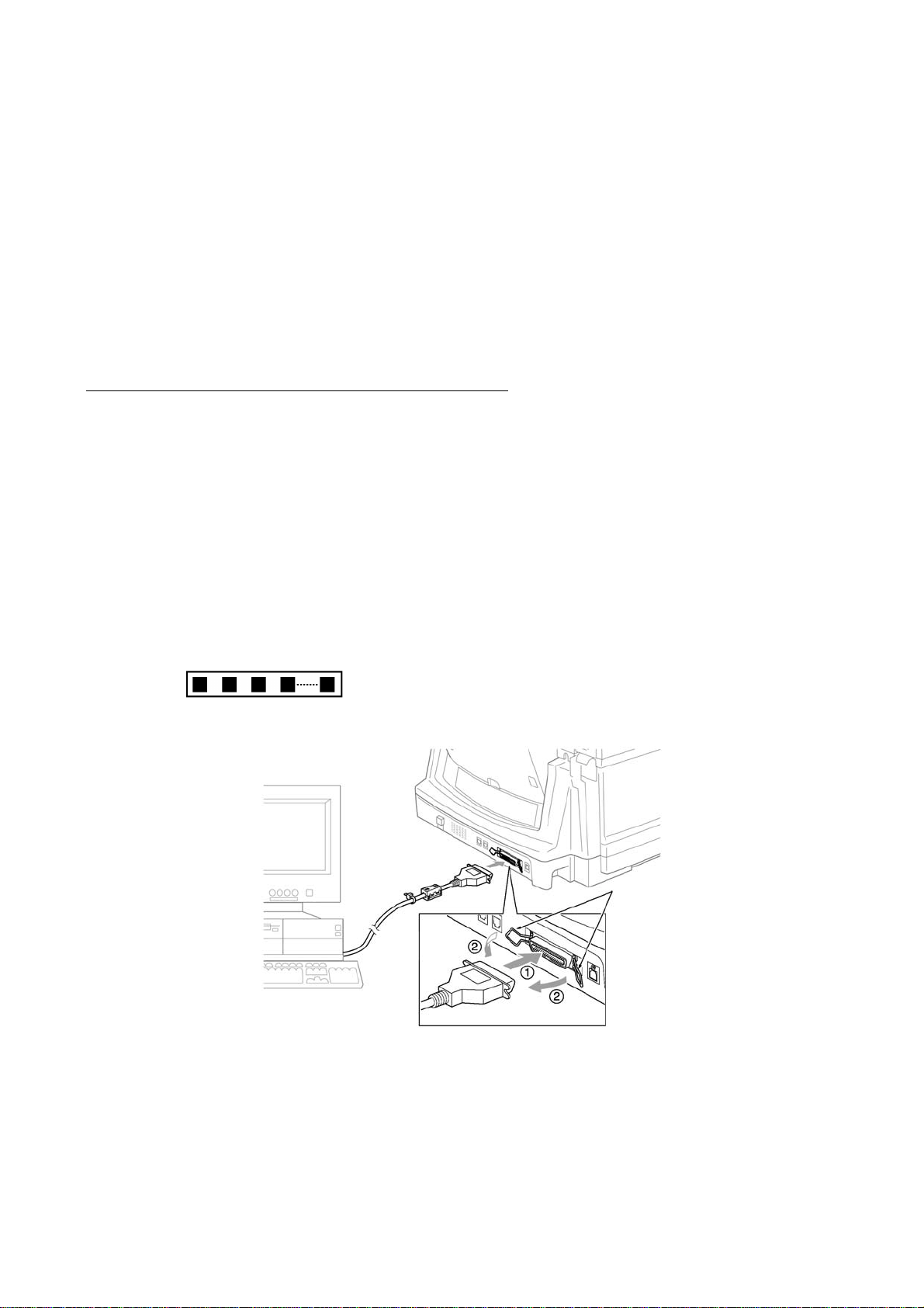
Connecting the facsimile machine to your PC
(1) Make sure that your PC is turned off.
(2) Make sure that the machine’s power cord is unplugged from a wall socket or other power
source.
(3) Connect the parallel interface cable to the parallel port on the back of the machine and secure
it with the lock wires.
(4) Connect the other end of the interface cable to the printer port of your PC and secure it with
two screws.
(5) While pressing the 5 key on the machine’s control panel, plug the machine’s power cord into a
wall socket.
(6) Check to see that the following pattern displays on the LCD. If it does not display, go back to
step (2) above.
(7) Turn on your PC.
Parallel interface
cable
Lock wires
Host computer
2-1

Installing the update data onto the flash ROM of the facsimile machine
NOTE: The following is an installation procedure example on a PC that is running Windows 95/98.
(1) Copy the update data and transfer utility onto the desired directory of the hard disk.
e.g., C:\UPDATE
(2) Click the Start button, point to Programs, and then click MS-DOS Prompt to open an MS-DOS
window.
(3) Type the drive letter where the update data and transfer utility are located. In the above
example, type C:\ from the command line and press the ENTER key.
Then type CD UPDATE and press the ENTER key.
(4) Check that your PC is connected with the facsimile machine correctly.
(5) To start the transfer utility transmitting the update data to the flash ROM of the facsimile
machine, type the following:
ICEN filename /b
Then press the ENTER key.
During downloading, the machine beeps intermittently.
Upon completion of the downloading, the machine beeps continuously.
NOTE: If the facsimile machine cannot return to the standby state af ter completion of downloading,
turn the power off and on.
2-2

2.2 SETTING ID CODES TO FACSIMILE MACHINES CONNECTED TO A SINGLE PC VIA THE USB PORT
Function
Brother facsimile machines are assigned unique ID codes (character strings) at the factory. If you
replace the main PCB of the machine, the machine will lose its assigned ID code so that it will not
be identified by the connected PC.
To connect those machines to a PC via USB, you need to assign ID codes (character strings) to
those individual machines according to the procedure given here. For models covered by this
manual, set serial numbers given to individual machines as ID codes.
Connecting each of facsimile machines to your PC
(1) Make sure that your PC is turned off.
(2) Make sure that the machine's power cord is unplugged from a wall socket or other power
source.
(3) Connect the interface cable to the parallel interface port on the back of the facsimile machine
and secure it with the lock wires.
(4) Connect the other end of the interface cable to the printer port of your PC and secure it with
the two screws.
(5) Plug the machine's power cord into a wall socket or other power source.
(6) Turn on your PC.
Operating Procedure
(1) On your PC, run the ID setup utility. Follow the instructions shown on the PC's screen and
enter the 9-digit serial number (e.g., G01012345) printed on the nameplate labeled to the back
of the facsimile machine as an ID code. Then press the Enter key.
The ID setting utility will transmit the ID code data from your PC to the facsimile machine
and then it will terminate.
The facsimile machine will automatically return to the standby mode.
(2) To check whether the entered character string (ID code) is correct, make the machine enter the
maintenance mode (refer to CHAPTER 5, Section 5.1) and then press the 1 key twice
(Subsection 5.3.5).
The facsimile machine will print out a Configuration List. At the right top of the list, "SER.#:
BROXXXXXXXXX" is printed.
(3) Check that the character string entered in step (2) is printed in "XXXXXXXXX."
If it is OK, press the 9 key twice to exit from the maintenance mode.
If something other than that is printed in XXXXXXXXX, check the connection between the
PC and facsimile machine and go back to step (1).
2-3

2.3 SETTING HEAD PROPERTY TO THE FACSIMILE MACHINE
Function
To keep the print quality, the controller optimizes the head drive strength, ink jet-out timing, and
other drive conditions according to the electromechanical properties unique to the individual print
head and ambient temperature. The head property information is stored in the EEPROM of the
main PCB.
If you replace the print head unit and/or main PCB of the machine, then you need to update the
head property according to the procedure given here.
Connecting the facsimile machine to your PC
(1) Make sure that your PC is turned off.
(2) Make sure that the machine's power cord is unplugged from a wall socket or other power
source.
(3) Connect the interface cable to the parallel interface port on the back of the facsimile machine
and secure it with the lock wires.
(4) Connect the other end of the interface cable to the printer port of your PC and secure it with
two screws.
(5) Plug the machine's power cord into a wall socket or other power source.
(6) Turn on your PC.
Operating Procedure
(1) On your PC, run the head property setup utility. Follow the instructions shown on the PC's
screen and enter upper 12 digits (e.g., 55557B657031) out of the 13-digit property code
(enclosed with asterisks, e.g., *55557B657031H*) which is printed on the bar code label
attached to the print head unit.
The utility will transmit the head property from your PC to the facsimile machine and then it
will terminate.
The facsimile machine will automatically return to the standby mode.
(2) To check whether the entered head property is correct, make the machine enter the
maintenance mode (refer to CHAPTER 5, Section 5.1) and then press the 7 key twice
(Subsection 5.3.15).
The facsimile machine will print out the Equipment's Log. On the line about 1/3 of full length
of the log sheet below from the top, the 12-digit code is printed.
(3) Check that the character string entered in step (2) is printed in "XXXXXXXXXXXX."
If it is OK, press the 9 key twice to exit from the maintenance mode.
If something other than that is printed in XXXXXXXXXXXX, check the connection between
the PC and facsimile machine and go back to step (1).
2-4

CHAPTER
THEORY OF OPERATION
3

CHAPTER 3 THEORY OF OPERATION
CONTENTS
3.1 OVERVIEW ......................................................................................................................3-1
3.2 MECHANISMS.................................................................................................................3-2
3.2.1 Scanner Mechanism ............................................................................................3-4
3.2.2 Ink Jet Printing Mechanism..................................................................................3-6
3.2.2.1 Paper pulling-in, registration, feeding, and ejecting mechanisms................3-6
3.2.2.2 Ink jet printing and capping mechanisms.....................................................3-8
3.2.2.3 Purging mechanism ...................................................................................3-11
3.2.2.4 Carriage drive mechanism .........................................................................3-14
3.2.3 Sensors and Actuators.......................................................................................3-15
3.3 CONTROL ELECTRONICS...........................................................................................3-18
3.3.1 Configuration......................................................................................................3-18
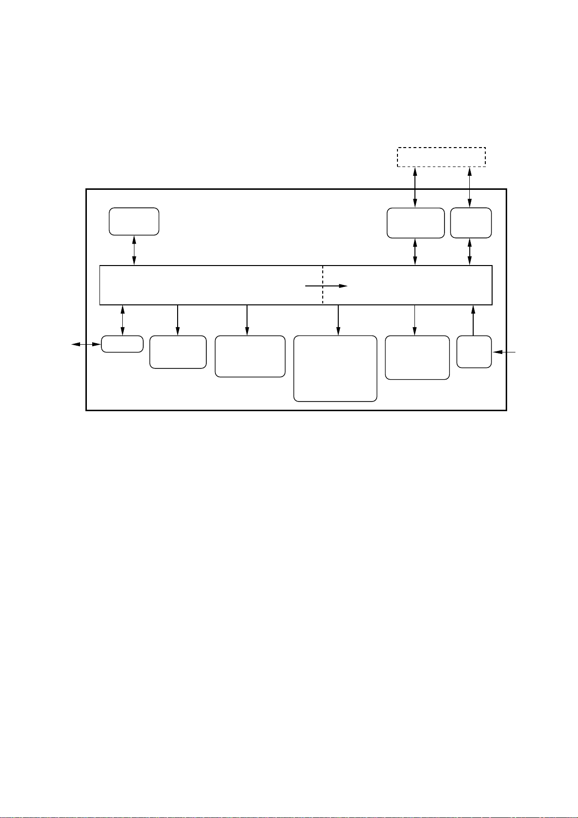
3.1 OVERVIEW
Host
Line
Control
panel
NCU
Fax Control Section
ADF unit
- ADF motor
Scanner unit
- CCD unit
- CCD motor
Print data
Ink jet printer unit
- Ink jet print head
unit
- Carriage motor
- Carriage ASSY
- Purge unit
Centronics
parallel
interface
Printer Control Section
Paper feeding
mechanism
- Paper feed
motor
USB
interface
Power
supply
AC
3-1

3.2 MECHANISMS
The facsimile machine is classified into the following mechanisms:
SCANNER MECHANISM - ADF mechanism
INK JET PRINTING MECHANISM - Paper pulling-in, registration, feeding, and ejecting
SENSORS AND ACTUATORS
- Document scanning mechanism
mechanisms
- Ink jet printing and head capping mechanisms
- Purging mechanism
- Carriage drive mechanism
3-2
SCANNER MECHANISM
3-3
Ink jet pri nting and head
capping mechanisms
Purge mechanism
Carriage drive mechanism
Paper pulling-in,
registration, feeding, and
ejecting mechanisms
INK JET
PRINTING
MECHANISM
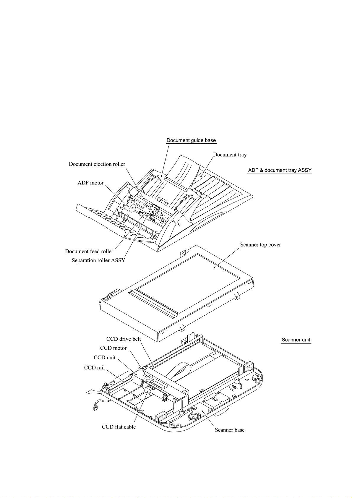
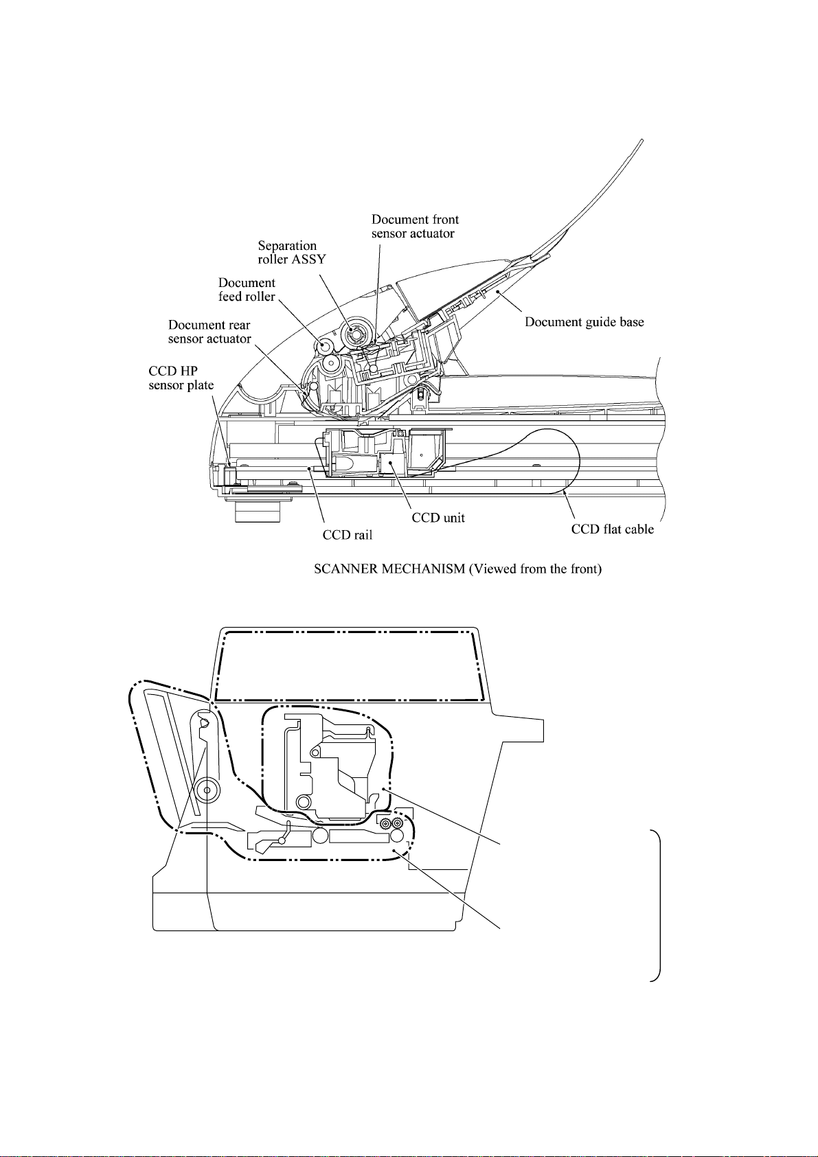
3.2.1 Scanner Mechanism
This mechanism consists of the document guide base, ADF & document tray ASSY and scanner
unit.
The ADF (automatic document feeder) unit contains a separation roller ASSY, document feed
roller ASSY, document ejection roller, ADF motor, and document front and rear sensors.
The scanner unit consists of a scanner top cover, CCD unit, CCD drive mechanism, CCD HP
sensor, and scanner base.
For details about the sensors, refer to Subsection 3.2.3.
3-4
This scanner mechanism supports a dual scanning system.
(1) If you set documents on the document guide base with their faces up and start the scanning
operation, then the ADF motor rotates to pull in those documents into the ADF unit, starting
from the top sheet to the bottom, page by page. Each document curves downwards and turns to
the right with the document feed roller so as to advance above the CCD unit, and then it is fed
out to the document tray with the document ejection roller ASSY.
This way, documents move above the CCD unit being kept in a stationary position.
(2) If you open the ADF & document tray ASSY, put a sheet of document (or put a bound book
opened) on the glass of the scanner top cover, close the ADF & document tray ASSY, and
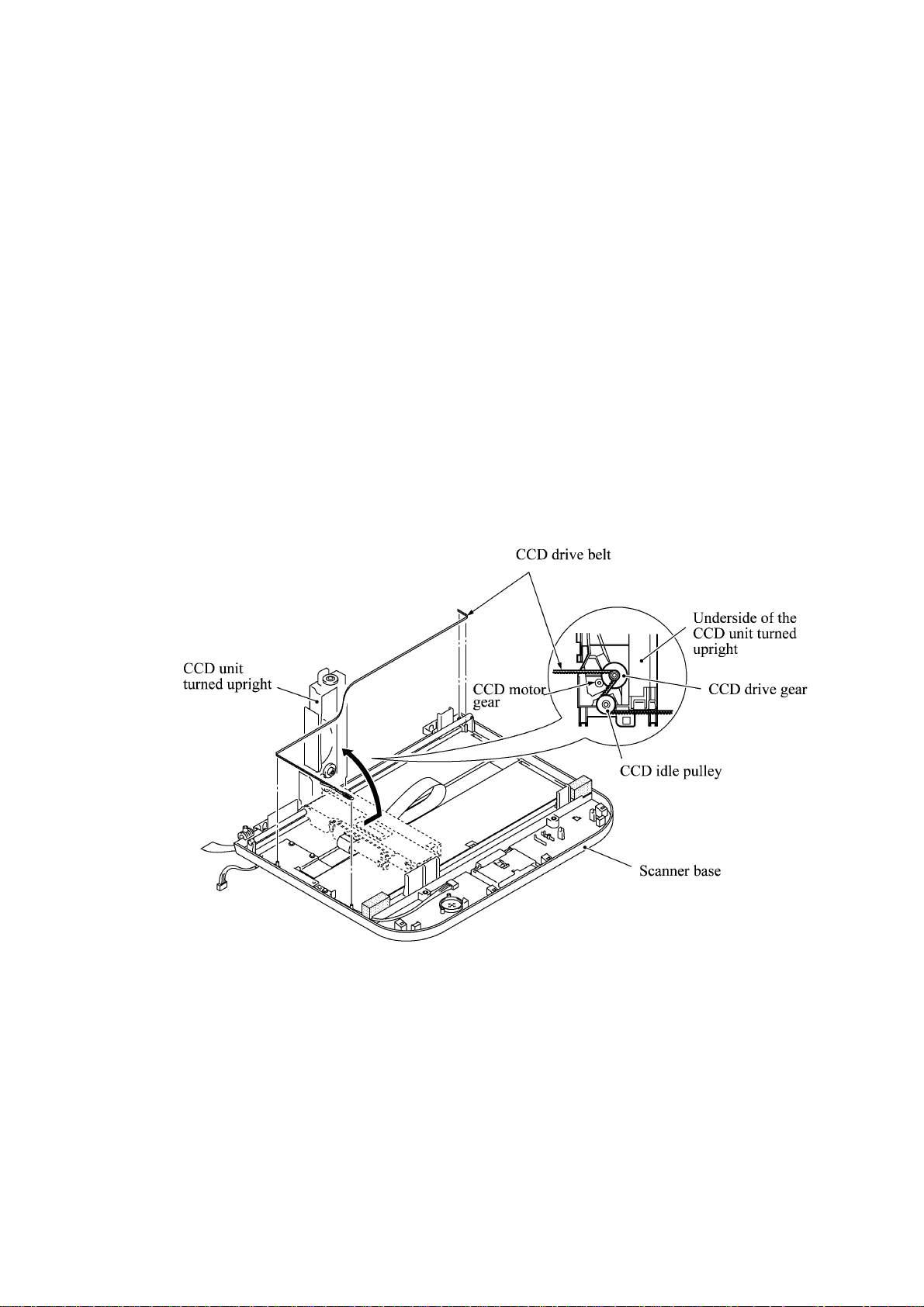
start the scanning operation, then the CCD drive mechanism will be driven.
The CCD motor built in the CCD unit rotates. As illustrated below, the CCD drive gear and
idle pulley carry the CCD drive belt on the underside of the CCD unit, so clockwise and
counterclockwise rotations of the CCD motor move the CCD unit to the right and left,
respectively.
In this scanning system, the CCD unit moves horizontally beneath a document being kept in
stationary position.
The CCD unit contains a charge coupled device (CCD) image sensor. The cold-cathode
fluorescent lamp illuminates a document and the reflected light of the scanned image data is
transmitted via the mirrors into the lens which reduces the scanned data so as to form the image on
the CCD.
3-5
3.2.2 Ink Jet Printing Mechanism
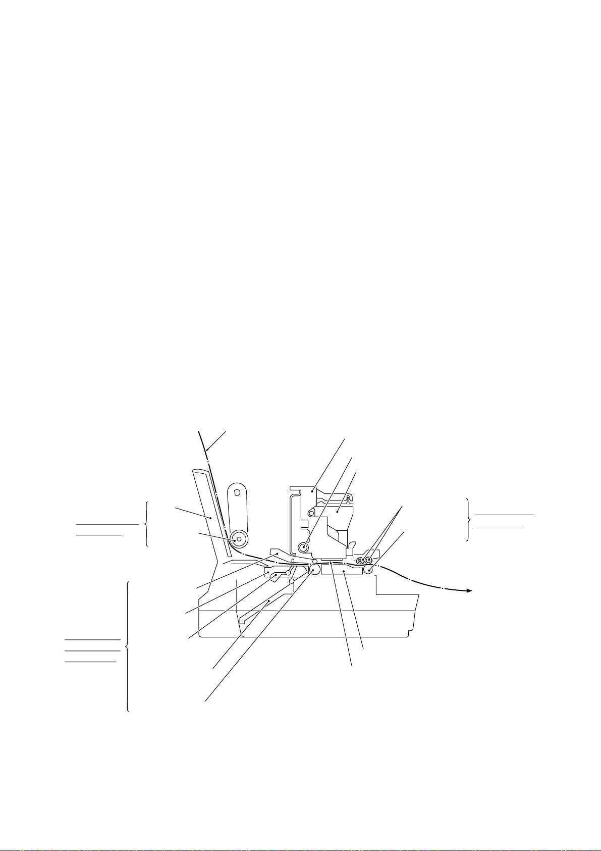
3.2.2.1 Paper pulling-in, registration, feeding, and ejecting mechanisms
The paper pulling-in, registration, feeding, and ejecting mechanisms are driven by a single paper
feed motor located at the left side of the main chassis via the gear train. (See the illustration given
on the next page.)
First, the paper feed motor rotates clockwise (when viewed from the output gear). The rotation is
transmitted to the PF roller gear that rotates paper feed roller. At the right end of the paper feed
roller is the PF roller gear R which is always engaged with the ASF/purge idle gear. Engaged with
the ASF/purge idle gear, the ASF-purge switching gear 23 transmits the rotation via gear 25 and
the ASF gear train to the ASF roller unit. This way, the ASF roller will pull in paper.
When the ASF roller is pulling in paper, the paper feed roller rotates in the backward direction to
register the leading edge of the pulled-in paper.
Next, the paper feed motor rotates counterclockwise to rotate the paper feed roller in the forward
direction. The paper will advance through the paper path. During the paper feeding operation, no
rotation is transmitted to the ASF roller because of the planetary gear system built in the ASF
roller unit.
The above paper pulling-in and feeding operations take place when the carriage is in printing
operation. If the carriage reaches the purge position, the ASF-purge switching gear 23 will be
disengaged from the gear 25 and engaged with purge bevel gear A. For the purging mechanism,
refer to Subsection 3.2.2.3.
Paper pulling-in
mechanism
Registration &
paper feeding
mechanisms
ASF
ASF roller
unit
Paper pressure
holders
Paper chute
Registration
sensor actuator
Paper width sensor
actuator
Paper feed roller
Recording paper
(Carriage)
(Carriage rail)
(Ink cartridges)
Platen
(Print head unit)
Star wheels
Paper ejection
roller
Paper ejecting
mechanism
3-6
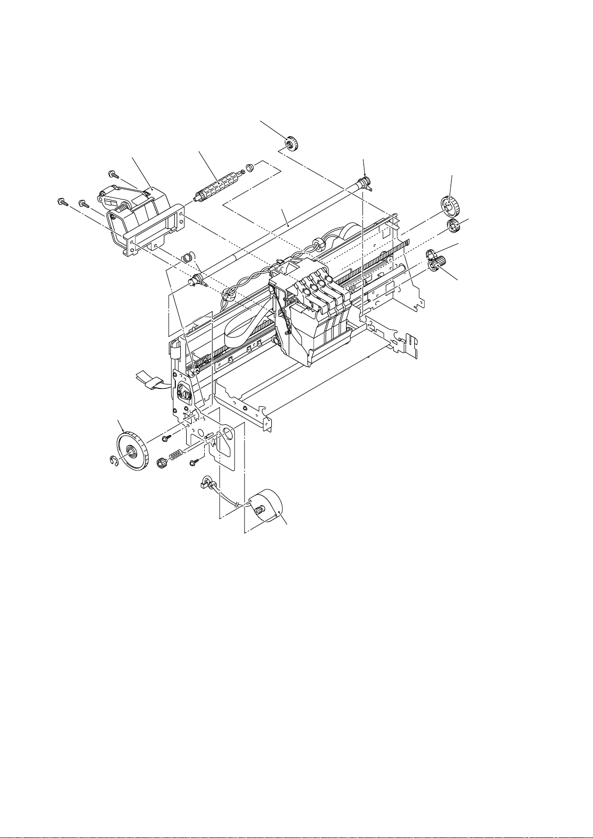
Gear 31MF
ASF roller unit
PF roller gear
Gear shaft 17
PF roller gear R
Gear 39
Paper feed
roller
Gear 25
ASF-purge
switching gear 23
ASF/purge idle gear
Paper feed motor
3-7
3.2.2.2 Ink jet printing and capping mechanisms
Carriage encoder
Carriage
motor
Carriage rail
(1) Print head unit
Main chassis
Platen
Carriage PCB
Ink cartridge sensors
Ink cartridges
Ink empty sensor
Carriage
(Star wheels)
(Paper ejection roller)
Print head unit
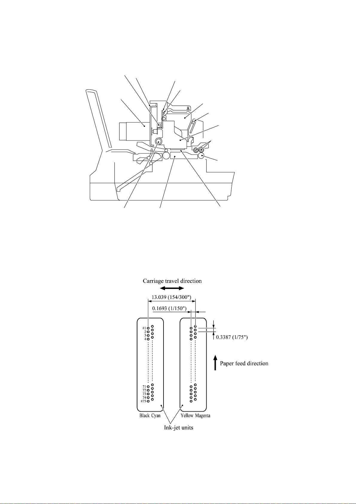
This machine uses drop-on-demand ink jet printing. Each of the right and left print heads has an
ink-jet unit that has a pair of nozzle columns for two color inks. A nozzle column consists of 75
nozzles, 75 channels covered with piezoelectric ceramic (PZT), a manifold, and filter. As
illustrated below, the pair of nozzle columns is staggered.
Nozzle Layout (viewed from the bottom)
3-8
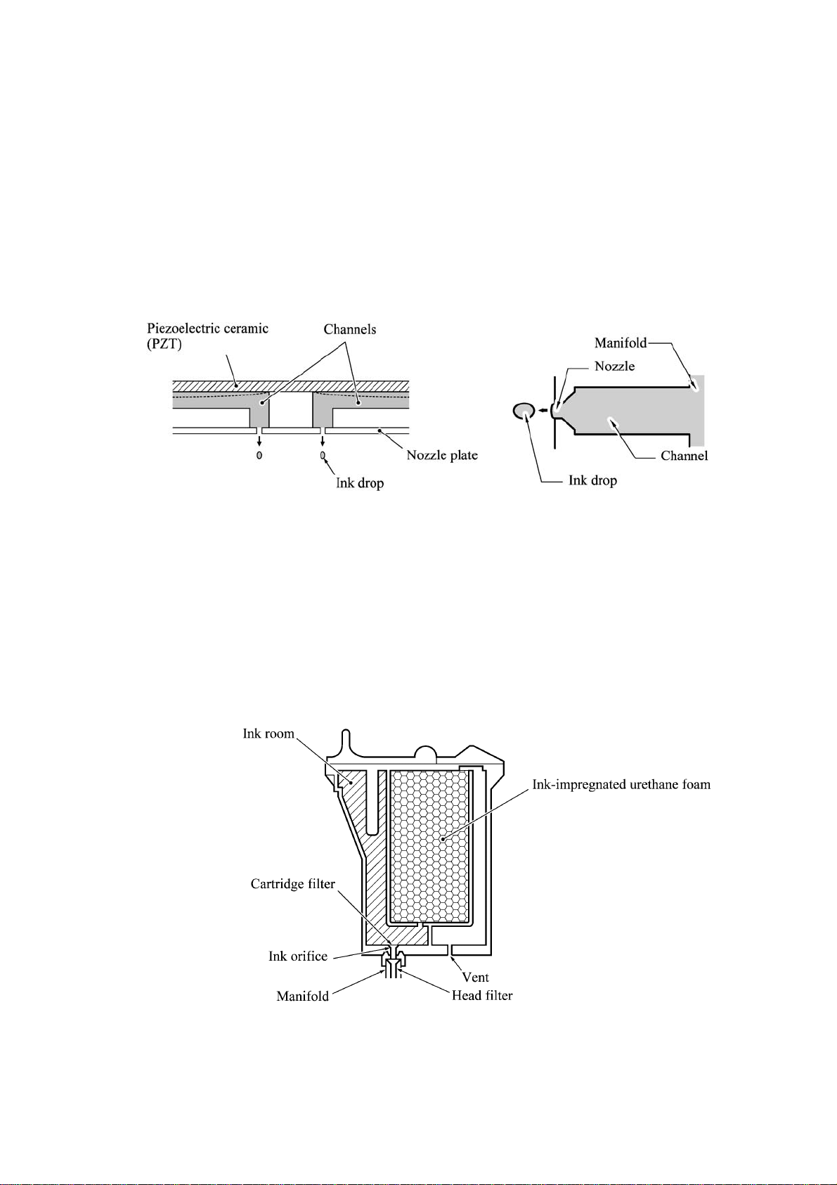
If the controller issues a print command, a biased voltage will be applied to all electrodes formed
on the surface of the piezoelectric ceramic so that each actuator will be distorted as shown with
broken lines.
If the electrodes on a target channel are deenergized according to drive signals, then the associated
piezoelectric ceramic actuator returns to the previous form so that the ink in the manifold will be
vacuumed out to the channel.
If the voltage is applied again, the piezoelectric ceramic actuator will be distorted again to apply
pressure to the ink in the channel, causing the ink to jet out through the nozzle. The jetted-out ink
drop will be splashed and produce a dot on paper held by the platen.
As the carriage holding the print head unit travels at the printing speed, the controller sends print
command pulses to the piezoelectric actuator driver circuit embedded in the print head unit.
(2) Ink cartridges
The machine uses four ink cartridges (black, cyan, yellow, and magenta) of disposable type to
supply ink to the print head unit. As shown below, an ink cartridge contains an ink-impregnated
urethane foam. If ink-jet print operation or purging operation takes place, ink comes out of the
urethane foam and is supplied to the print head unit through the ink room, filters, and manifold.
For the ink cartridge sensors on the carriage PCB, refer to Subsection 3.2.3.
3-9
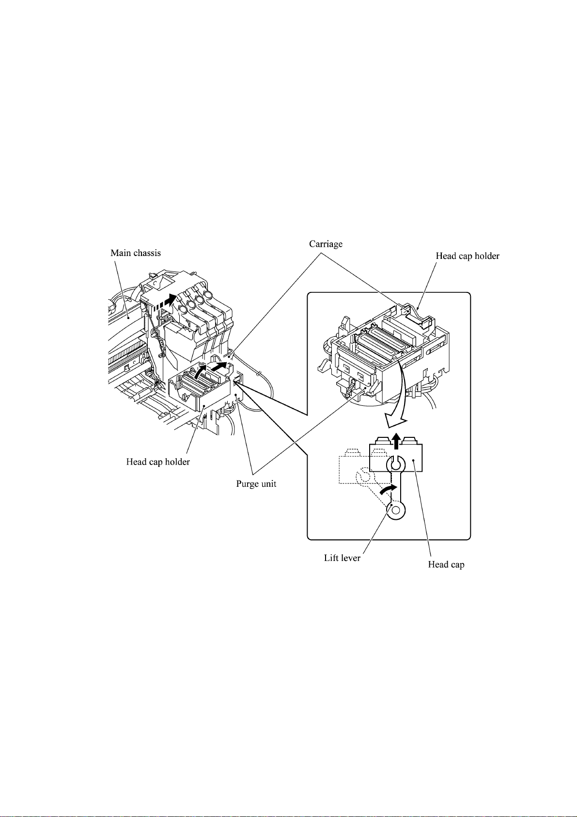
(3) Head cap
Shown below is a head cap mechanism that prevents the nozzles of the print heads from drying up
when they are not in use.
Upon completion of printing, the carriage travels to the right and moves the head cap holder
provided on the purge unit to the right together. In the head cap holder is a head cap which is
supported with a lift lever. The rightward movement of the head cap holder turns the lift lever and
pushes up the head cap to the position where the head cap comes into tight contact with the print
heads. This way, the nozzles will be capped.
3-10
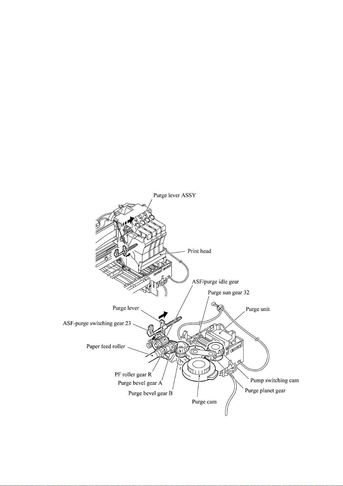
3.2.2.3 Purging mechanism
The purge mechanism is driven by the paper feed motor located at the left side of the main chassis.
As described in Subsection 3.2.2.1, the motor rotation is transmitted to the ASF/purge idle gear at
the right side of the main chassis. Engaged with the ASF/purge idle gear, the ASF-purge switching
gear 23 works as a clutch gear.
When the carriage travels from the left to right to reach the purge position, the tab provided on the
back of the carriage pushes the purge lever on the main chassis to the right (see the illustration
below). Accordingly, the ASF-purge switching gear 23 (which was shifted to the left by the purge
lever) will move to the right by the switching gear spring so as to become disengaged from the
gear 25 and engaged with the purge bevel gear A. (See the illustration given on the next page.)
This engagement will transmit the motor rotation to the purge bevel gear B on the purge unit. This
way, when the carriage is in the purge position, the motor rotation is transmitted to the purge unit.
On the contrary, if the carriage travels from the purge position to the left, the tab on the back of the
carriage releases the purge lever which will be pulled back to the left. The ASF-purge switching
gear 23 will be disengaged from the purge bevel gear A.
3-11
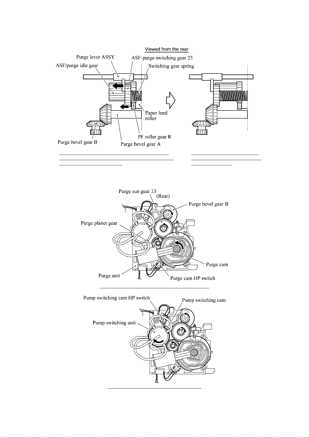
During printing: The ASF-purge switching gear 23 is
not engaged with pur ge bevel gear A ( but engaged with
gear 25 in the ASF gear train).
During purging: T he ASF-purge
switching gear 23 is engaged with
purge bevel gear A.
When the motor rotation is transmitted to the purge unit, its counterclockwise rotation will drive
the purge cam and its clockwise rotation, the pump switching unit (when viewed from the output
gear of the motor).
When the paper feed motor rotates counterclockwise
When the paper feed motor rotates clockwise
3-12

The purge cam is so designed that:
- the carriage lock pops out to lock the carriage before purging and pops in before cleaning with
the head wiper (see the illustration below),
- the pump works to draw out ink from each of the four head nozzles and drain it to the ink
absorber felts, and
- the head wiper comes out to clean the nozzle surface (see the illustration below).
The pump switching cam is so designed that:
- the pump switching unit switches application of the pump's negative pressure between the four
head nozzles in the order of black, cyan, yellow, and magenta nozzles. When the pump
switching cam is in the home position, normal atmospheric pressure will be restored.
The home position of the purge cam and pump switching cam are detected by their HP switches.
For those switches, refer to Subsection 3.2.3.
(1) Carriage lock
If the purge cam is driven, the carriage lock of the purge unit pops out and locks the carriage to
align ink-jet unit with the mating purge caps during purge operation. After purging but before
cleaning with the head wiper, it pops in to release the carriages. When the power is off, the
carriage lock keeps the print heads pressed against the head caps.
(2) Purging
If activated, the pump draws out ink to purge air bubbles or dust from the inside of the head
nozzles and channels. As the purge cam rotates by one turn, the piston of the pump reciprocates
two strokes. To complete purging of all four nozzles and channels, the purge cam rotates by two
turns ad the piston reciprocates four strokes.
(3) Draining
The pump drains drawn ink into the ink absorber felts.
(4) Cleaning with the head wiper
After purging operation, the head wiper comes out and the carriage moves from the right to left so
as to clean ink remaining on the heads' surface.
(5) Restoring the pump's pressure to normal atmospheric pressure
When the pump switching cam is in the home position, the controller stops to produce negative
pressure and restore the pump's pressure to normal atmospheric pressure.
3-13

3.2.2.4 Carriage drive mechanism
The carriage motor controls horizontal motion. The motor rotation is transmitted via the motor
pulley to the timing belt.
The carriage, which is supported and guided by the carriage rail, is secured to the timing belt.
Clockwise and counterclockwise rotations of the carriage motor move the carriage to the right and
left, respectively.
On the back of the carriage is the carriage encoder which tells the control circuitry the current
carriage position counted based on the carriage motor position by using the encoder strip attached
to the main chassis.
3-14

3.2.3 Sensors and Actuators
This machine has the following sensors and thermister.
Sensor name Type Located on
Document front sensor Photosensor
Document rear sensor Photosensor
Document sensor PCB in
the ADF
Document tray open sensor Mechanical switch Document tray
Scanner open sensor Photosensor Control panel PCB ASSY
Registration sensor Photosensor Paper chute
Paper width sensor Photosensor Main PCB
CCD HP sensor Photosensor CCD PCB on the CCD unit
Ink empty sensor Photosensor Sensor support
Ink cartridge sensors Mechanical switches
Carriage encoder Photosensor
Carriage PCB
Head thermister Thermister
Purge cam HP switch Mechanical switch
Purge unit
Pump switching cam HP switch Mechanical switch
• Document front sensor which detects the presence of documents.
• Document rear sensor which detects the leading and trailing edges of pages to tell the control
circuitry when the leading edge of a new page has reached the starting position and when the
scan for that page is over.
• Document tray open sensor which detects whether the document tray is closed.
• Scanner open sensor which detects whether the scanner unit is closed.
• Registration sensor which detects the leading and trailing edges of paper, which allows the
controller to determine the registration timing and check paper jam.
• Paper width sensor which detects whether the paper width is "A4-size or wider" or "narrower
than A4-size."
• CCD HP sensor which detects whether the CCD unit is placed in the home position.
• Ink empty sensor which detects at the start of printing whether any of the four ink cartridges is
near empty. According to this sensor signal, the controller may display "NEAR EMPTY XXX"
message.
• Ink cartridge sensors, each of which detects whether an ink cartridge is loaded.
• Carriage encoder which detects the current carriage position and carriage travel speed. If the
carriage travels speed varies abnormally, the controller regards it as a paper jam.
• Head thermister which allows the controller to control the temperature of the print heads.
According to the change of the thermister's internal resistance monitored, the control circuitry
regulates the drive voltage applied to the piezoelectric ceramic actuators on each print head
since the viscosity of the ink varies depending upon the temperature.
3-15

• Purge cam HP switch which detects whether the purge cam is in the home position.
• Pump switching cam HP switch which detects whether the pump switching cam is in the home
position.
These photosensors (except the ink empty sensor that is a reflection type) are a photointerrupter
consisting of a light-emitting diode and a light-sensitive transistor. Each of them has an actuator
separately arranged as shown on the next page.
3-16

Registration sensor
Registration sensor
actuator
(Paper chute)
Document front sensor actuator
Document front sensor
(Document sensor PCB)
Document tray open sensor
(Relay PCB)
Document rear sensor actuator
Document rear sensor
CCD HP sensor
CCD HP sensor plate
Paper width sensor
Paper width sensor actuator
(Main PCB)
Scanner open sensor actuator
Scanner open sensor
(Control panel PCB)
(Purge unit)
Purge cam HP switch
Pump switching cam HP switch
Ink empty sensor
(Sensor support)
Location of Sensors and Actuators
3-17

3.3 CONTROL ELECTRONICS
3.3.1 Configuration
The hardware configuration of the facsimile machine is shown below.
Carriage PCB
Paper width sensor
Ink cartridge sensors
Carriage encoder
Head thermister
INK JET
PRINTER
UNIT
Print head
Print head
EEPROM
Engine
GA
Main
ASIC
Main PCB
DC motor
driver
Stepping
motor driver
SDRAM
(8MB/2MB)
3-pin
3-pin
2-pin
4-pin
4-pin
Ink empty sensor
Registration sensor
Carriage motor
Paper feed motor
Purge cam HP switch
Pump switching cam HP switch
2-pin
12-pin
11-pin
9-pin
4-pin
4-pin
Relay
PCB
7-pin
Sensor
support
Paper
chute
Purge unit
Document tray
open sensor
Document sensor PCB
(Document front sensor
and document rear sensor)
ADF motor
ADF UNIT
CCD unit
(CCD motor)
(CCD HP sensor)
SCANNER
UNIT
ROM
(2MB)
USB
MODEM
Parallel interface
(ECP)
PC
7-pin
(10-pin)*
11-pin
Power supply
PCB
NCU PCB
AC line
* 7-pin: American models
10-pin: Other models
Configuration of Facsimile Machine
3-18
Control panel PCB ASSY
(Scanner open sensor)
Piezo ringer
Line
External telephone

CHAPTER
DISASSEMBLY/REASSEMBLY,
LUBRICATION, AND ADJUSTMENT
4

CHAPTER 4 DISASSEMBLY/REASSEMBLY, LUBRICATION,
ADJUSTMENT
CONTENTS
4.1 DISASSEMBLY/REASSEMBLY......................................................................................4-1
Safety Precautions.......................................................................................................4-1
Tightening Torque List......................................................................................................4-2
Preparation ..................................................................................................................4-4
How to Access the Object Component........................................................................4-4
Disassembly Order Flow..............................................................................................4-5
4.1.1 Print Head Unit.....................................................................................................4-6
4.1.2 ADF Cover and Document Guide Base .............................................................4-10
4.1.3 ADF Components on the Upper ADF Chute......................................................4-11
Gear cover ...........................................................................................................4-11
Separation roller ASSY and document feed roller....................................................4-12
Separation rubber unit, ADF thickness adjuster, and pressure rollers.........................4-13
Upper ADF chute..................................................................................................4-15
4.1.4 ADF Components on the Lower ADF Chute......................................................4-16
Document front and rear sensor actuators................................................................4-16
Document sensor PCB...........................................................................................4-16
Document guide clips............................................................................................4-17
Document ejection roller.......................................................................................4-17
Document pressure bar..........................................................................................4-18
Lower ADF chute, pinch r ollers, and ADF moto r.....................................................4-19
4.1.5 Document Tray Open Sensor and Document Stopper ......................................4-21
4.1.6 Jam Clear Cover, Rear Cover, and Inner Cover................................................4-22
4.1.7 Scanner Unit and Control Panel ASSY (Together with Document Tray) ...........4-23
4.1.8 Disassembly of the Control Panel ASSY............................................................4-28
4.1.9 Disassembly of the Scanner Unit.......................................................................4-29
4.1.10 Auto Sheet Feeder (ASF) and Separation Pad ASSY .......................................4-34

4.1.11 Edge Cover, Scanner Links and Their Guides...................................................4-36
4.1.12 Relay PCB and PCB Plate .................................................................................4-37
4.1.13 Bottom Plate, Ink Absorber Box, Main PCB, NCU PCB, and
Power Supply PCB.............................................................................................4-38
4.1.14 Enclosure Cover.................................................................................................4-42
4.1.15 Main Cover.........................................................................................................4-43
4.1.16 Purge Unit ..........................................................................................................4-45
4.1.17 Main Chassis......................................................................................................4-47
4.1.18 ASF Roller Unit and its Related Gears...............................................................4-49
4.1.19 Paper Pressure Holders.....................................................................................4-51
4.1.20 Paper Chute and Registration Sensor................................................................4-52
4.1.21 Paper Ejection Roller Gear, Ink Empty Sensor PCB, Platen,
Star Wheel Support, and Paper Ejection Roller.................................................4-54
4.1.22 Paper Feed Motor and Paper Feed Roller .........................................................4-57
4.1.23 Encoder Strip and Carriage Motor......................................................................4-58
4.1.24 Carriage Rail, Carriage ASSY, and Purge-Related Parts ..................................4-60
4.1.25 Flushing Gutter and Paper Width Sensor Actuator............................................4-65
4.1.26 Harness Routing.................................................................................................4-66
4.2 LUBRICATION...............................................................................................................4-68
4.3 ADJUSTMENT...............................................................................................................4-73

4.1 DISASSEMBLY/REASSEMBLY
Safety Precautions
To prevent the creation of secondary problems by mishandling, observe the following precautions
during maintenance work.
(1) Unplug the power cord from the power outlet before replacing parts or units. When having
access to the power supply, be sure to unplug the power cord from the power outlet.
(2) Be careful not to lose screws, washers, or other parts removed for parts replacement.
(3) Do not remove gears from the document feed roller ASSY or ejection roller ASSY if at all
possible. Once removed, they will become unusable and new gears will have to be put back in.
(4) When using soldering irons and other heat-generating tools, take care not to damage the resin
parts such as wires, PCBs, and covers.
(5) Before handling the PCBs, touch a metal portion of the machine to discharge static electricity;
otherwise, the electronic parts may be damaged due to the electricity charged in your body.
(6) When transporting PCBs, be sure to wrap them in conductive sheets such as aluminum foil.
(7) Be sure to reinsert self-tapping screws correctly, if removed.
(8) Tighten screws to the torque values listed on the next page.
(9) When connecting or disconnecting cable connectors, hold the connector bodies not the cables.
If the connector has a lock, always slide the connector lock to unlock it.
(10) Before reassembly, apply the specified lubricant to the specified points. (Refer to Subsection
4.2 in this chapter.)
(11) After repairs, check not only the repaired portion but also that the connectors and other related
portions function properly before operation checks.
(12) Once the print head unit prints, it will start head locking operation after five seconds from the
end of printing. The head locking operation will take 5 to 10 seconds. NEVER unplug the
power cord before the machine completes the head locking operation; doing so will make the
print head unit unusable and require replacement with a new print head unit.
When you receive the machine from the user or when you pack it for sending it back to the
user, check the head locking state.
4-1

Tightening Torque List
Location Screw type Q'ty Tightening torque
N•m (kgf•cm)
ADF thickness adjuster Taptite, pan B M3x6 1 0 .39 ±0.10 (4 ±1)
Upper ADF chute Taptite, cup B M3x10 2 0.69 ±0.10 (7 ±1)
Lower ADF chute Taptite, cup B M3x10 2 0.69 ±0.10 (7 ±1)
Grounding wire Taptite, cup B M3x8 1 0.69 ±0.10 (7 ±1)
ADF drive unit Taptite, cup B M3x8 2 0.69 ±0.10 (7 ±1)
ADF motor Screw, pan (s/p washer) M3x6 1 0.69 ±0.10 (7 ±1)
Rear cover Taptite, cup B M3x12 2 0.69 ±0.10 (7 ±1)
Grounding wires Screw, bind B tite M4x16 1* 0.98 ±0.20 (10 ±2)
(from the ADF drive unit and relay PCB)
Document tray Taptite, bind B M4x12 2 0.9 8 ±0.20 (10 ±2)
Hinge base R Taptite, cup B M3x10 3 0.59 ±0.10 (6 ±1)
Hinge L Taptite, cup B M3x10 3 0.59 ±0.10 (6 ±1)
Control panel ASSY Taptite, cup B M3x12 6 0.49 ±0.10 (5 ±1)
Scanner open sensor PCB Taptite, cup B M3x8 1 0.59 ±0.10 (6 ±1)
Piezo ringer cap Taptite, cup B M3x12 3 0.59 ±0.10 (6 ±1)
Reinforcement plate Taptite, cup B M3x6 7 0.49 ± 0 .10 (5 ±1)
Control panel PCB Taptite, cup B M3x6 2 0.49 ±0.10 (5 ±1)
Scanner top cover Taptite, cup B M4x12 4 0.98 ±0.20 (10 ±2)
Guide plate Taptite, cup B M3x8 3 0.69 ±0.10 (7 ±1)
CCD HP sensor plate Taptite, cup B M3x8 1 0.69 ±0.10 (7 ±1)
Flat cable clamp Taptite, cup B M3x8 2 0.69 ±0.10 (7 ±1)
ASF Taptite, cup B M3x12 4 0.69 ±0.10 (7 ±1)
Edge cover Tap tite, cup B M3 x12 2 0.69 ±0.10 (7 ±1)
Scanner link guides Taptite, cup B M3x12 2 0.69 ±0.10 (7 ±1)
Relay PCB cover Taptite, cup B M3x6 1 0.69 ±0.10 (7 ±1)
Relay PCB Taptite, cup B M3x6 1 0.69 ±0.10 (7 ±1)
USB I/F connector Screw, pan M3x6 1 0.39 ±0.10 (4 ±1)
Parallel I/F connector Screw, pan M3x6 2 0.39 ±0.10 (4 ±1)
Bottom plate Taptite, cup B M3x12 11 0.69 ±0.10 (7 ±1)
Grounding terminal Screw, pan (washer) M4x8 1 0.59 ±0.20 (6 ±2)
Ink absorber box Taptite, cup B M3x12 1 0.78 ±0.10 (8 ±1)
Main cover Screw, bind B tite M4x16 3 (4)* 0.98 ±0.20 (10 ±2)
Side frame supporter Screw, pan (s/p washer) M3x6 1 0.69 ±0.10 (7 ±1)
Purge unit Taptite, cup B M3x8 2 0.59 ±0.10 (6 ±1)
FG plate R (Lower cover) Taptite, cup B M3x12 1 0.78 ±0.10 (8 ±1)
(Main chassis) Taptite, cup S M3x5 1 0.78 ±0.10 (8 ±1)
FG plate L (Main chassis) Taptite, cup S M3x5 1 0.78 ±0.10 (8 ±1)
Shield film (Main chassis) Taptite, cup S M3x5 1 0.59 ±0.10 (6 ±1)
[ (Lower cover) Taptite, cup S M3x5 1 0.59 ± 0.10 (6 ±1) ]
Chassis supporters R and L Taptite, cup B M3x12 2 0.78 ±0.10 (8 ±1)
* The main cover is secured with four screws together with the two grounding wires.
4-2

Location Screw type Q'ty Tightening torque
N•m (kgf•cm)
ASF roller unit Taptite, cup S M3x6 3 0.98 ±0.10 (10 ±1)
ASF gear holders Taptite, cup B M3x10 1 0.49 ± 0.10 (5 ± 1 )
Paper chute Taptite, cup S M3x6 1 0.98 ±0.10 (10 ±1)
Ink empty sensor PCB Taptite, cup B M3x8 1 0.59 ±0.10 (6 ±1 )
Platen Shoulder screw 1 0.59 ±0.10 (6 ±1)
Screw, bind B tite, M3x10 1 0.5 9 ±0.10 (6 ±1)
Platen plate R Taptite, bind B M2.6x10 1 0.3 9 ±0.10 (4 ±1)
Platen plate L Taptite, bind B M2.6x10 1 0.39 ±0 .1 0 (4 ±1)
Paper feed motor Screw, pan (s/p washer) M3x6 2 0.78 ±0.10 (8 ±1)
Idle pulley holder Taptite, cup S M3x8 1 0.98 ±0.10 (10 ±1)
Shoulder screw 1 0.78 ±0.10 (8 ±1)
Screw, cup S tite, M3x6 1 0.98 ±0.10 (10 ±1)
Carriage motor Screw, pan (s/p washer) M3x6 2 0.78 ±0.10 (8 ±1)
Eccentric bushings R, L Screw, pan (s/p washer) M3x6DB 2 0.78 ±0.10 (8 ±1)
Flushing gutter Taptite, cup B M3x12 1 0.69 ±0.10 (7 ±1)
4-3

Preparation
Prior to proceeding to the disassembly procedure,
(1) Unplug
- the modular jack of the telephone line,
- the PC interface cable if connected (Not shown below), and
- the modular jack of an external telephone set if connected (Not shown below).
(2) Remove
- the paper wire extension and
- the paper tray.
NOTE: Do not remove the ink cartridges when disassembling the machine except when removing
the print head unit.
Telephone line cord
Paper wire extension
Paper tray
How to Access the Object Component
• On the next page is a disassembly order flow which helps you access the object components.
To remove the purge unit, for example, first find it on the flow and learn its number (
case). You need to remove parts numbered
purge unit.
• Unless otherwise specified, the disassembled parts or components should be reassembled in the
reverse order of removal.
in this
, , , , , and so as to access the
4-4

Disassembly Order Flow
4.1.6
Jam clear cover
Rear cover
4.1.10
Auto sheet feeder (ASF)
- Separation pad ASSY
4.1.6
4.1.12
4.1.13
4.1.7
Scanner unit with document tray
4.1.7
Document tray
Hinges
(NOTE 2)
4.1.9
Scanner unit
Inner cover
PCB plate
Main PCB
4.1.5
Document tray
open sensor
4.1.12
4.1.12
(NOTE 1)
Scanner top cover
CCD drive belt
CCD unit
(NOTE 3)
4.1.7
CCD flat cable
4.1.13
Relay PCB cover
Relay PCB
4.1.5
Document
stopper
Scanner open lever
Lever spring
Scanner open sensor
actuator
Piezo ringer
Ink absorber box
4.1.13
Bottom plate
4.1.13
4.1.14
4.1.2
ADF cover
4.1.2
Document guide
base
Power supply
PCB
Enclosure cover
4.1.7
Control panel ASSY
4.1.8
- Control panel PCB with
scanner open sensor PCB
- Reinforcement plate
- FPC key
- LCD
- Keys
4.1.13
NCU PCB
(NOTE 4)
4.1.3
ADF components on the
upper ADF chute
Separation roller ASSY
Separation rubber unit
ADF thickness adjuster
4.1.4
ADF components on the
lower ADF chute
Document sensor actuators
Document sensor PCB
Gear cover
Upper ADF chute
(NOTE 5)
Document feed roller
Pressure rollers
Document guide clips
Document ejection roller
Lower ADF chute
Pinch rollers
Document pressure
bar
ADF motor
4.1.15
Main cover
4.1.17
Main chassis
4.1.18
ASF roller unit
and its gears
4.1.19
Paper pressure holders
4.1.20
Paper chute
- Registration sensor
4.1.21
Platen
- Star wheel support
- Platen plates
- Flushing sponge
- Paper ejection roller
4.1.17
Vibration absorbers
(Rubber bushings)
4.1.17
FG plates
(NOTE 7)
4.1.11
Edge cover
Scanner links
Scanner link guides
Scanner link springs
4.1.23
4.1.23
4.1.21
4.1.21
4.1.22
Paper feed roller
4.1.25
4.1.1
4.1.16
Purge unit
(NOTE 6)
Idle pulley holder
Carriage motor
Paper ejection
roller gear
Sensor support
Ink empty sensor PCB
(NOTE 8)
4.1.22
PF roller gear
Flushing gutter
Print head unit
4.1.23
Encoder strip
4.1.24
Carriage rail
4.1.24
Carriage ASSY
4.1.24
Purge-related parts
4.1.22
Paper feed motor
4.1.25
Paper width sensor
actuator
4.1.24
Carriage PCB
(with head flat
cables)
(NOTE 9)
(NOTE 1) On the main PCB is a paper width sensor.
(NOTE 2) On the document tray is a document tray open sensor.
(NOTE 3) On the CCD unit is a CCD HP sensor.
(NOTE 4) On the control panel PCB ASSY is a scanner open sensor.
(NOTE 5) On the document sensor PCB in the ADF are a document
front sensor and document rear sensor.
(NOTE 6) On the purge unit are a purge cam HP switch and pump
switching cam HP switch.
(NOTE 7) On the paper chute is a registration sensor.
(NOTE 8) On the sensor support is an ink empty sensor.
(NOTE 9) On the carriage PCB are four ink cartridge sensors,
a carriage encoder, and head thermister.
4-5

4.1.1 Print Head Unit
During disassembly jobs (except when removing the purge unit, carriage rail, or carriage
ASSY), the print head unit and all the four ink cartridges should be kept in place.
NOTE: To replace the print head unit with a new one, you need to move the carriage to the ink
replacement position by placing the machine in the ink replacement mode. Do not move the
carriage by hand when the power is off.
NOTE: If you replace the print head unit with a new one, replace also the ink absorber box and
ink cartridges with new ones.
(1) Plug the power cord into a wall socket.
(2) Press the Ink key to place the machine in the ink replacement mode.
(3) Press the 2 key to choose "2. REPLACE INK."
(4) Press the Menu/Set key.
The carriage automatically moves left to the ink replacement position.
(5) Unplug the power cord from the wall socket.
(6) Pull the scanner open lever towards you and open the scanner unit.
Scanner unit
Scanner open
lever
(7) Push the colored ink cartridge covers and remove all ink cartridges. (Or, remove the shipping
cover.)
PUSH
PUSH
PUSHPUSH
Ink cartridge covers
4-6

(8) Pull the head clamp springs in the direction of arrows shown below to release the print
head unit.
(9) Lift the print head unit up and out of the carriage (arrow
Head clamp spring
Scanner unit
Head clamp spring
Boss of the print head unit
).
Carriage
Head clamp spring
Print head unit
Locks provided on the carriage
NOTE: Do not touch the printing ends (nozzles) of the print head unit or the ink orifices of
the ink cartridges; doing so will not only stain your hands with ink but result in an ink jet-out
failure. Once you touch them, clean them with a dedicated cleaning stick and liquid.
NOTE: Be sure to put a head nozzle seal and filter seal on the print head unit as shown below.
Leaving the print head unit without those seals will dry up its printing ends and filters,
resulting in a damaged head.
NOTE: Do not touch the dimple contact section of the print head unit.
4-7

NOTE: Once the ink cartridges are removed, their colored covers rise upright. If you turn the
machine upside down with those covers being upright, then they will break. To prevent it, set
them to the horizontal position by turning them in the direction of arrow
up in the direction of arrow
.
and pushing them
(10) Turn the head adjuster lever located on the right side of the carriage to position 1.
(11) To install a new (or removed) print head unit, remove the head nozzle seal.
(12) Put the print head unit into the carriage with care for the dimple contact so that the electrical
contact on the head PCB comes into uniform contact with that on the carriage PCB as
illustrated below.
4-8

(13) Press the front center of the carriage to the rear and move the print head unit to the right and
left several times. This is to assure the dimple contact between the head PCB and carriage
PCB.
(14) While pressing the front center of the print head unit, lock the print head unit with the head
clamp springs.
(15) Remove the head filter seal.
(16) Set new ink cartridges into the carriage.
(17) Press the bottom right front corner of the carriage to the rear.
(18) Close the scanner unit.
(19) Plug the power cord into a wall socket.
The carriage automatically moves to the right-hand home position.
(20) Follow the instructions shown on the LCD.
NOTE: The machine enters a "head cleaning" cycle that takes approx. 3 minutes for each ink
cartridge.
(21) Load paper into the ASF.
(22) Correct the positioning error of the print head unit, referring to Section 4.3 "ADJUSTMENT."
(23) Adjust the alignment of vertical print lines, referring to CHAPTER 5, Subsection 5.3.12.
4-9

4.1.2 ADF Cover and Document Guide Base
(1) Open the ADF cover, press its front end to release the boss, and take it off (in the direction of
arrows
Inside of the ADF cover
, , and ).
ADF cover
Stopper tab
Setting the ADF cover back into place
Boss
Correct Wrong
(2) Remove the document support.
(3) Release the two latches of the document guide base and slide it up straight along the guides.
NOTE: Do not turn it to the left. Doing so will break the groove sections of the document
guide base.
Document support
Document guide base
Groove
Latches
ADF & document
tray ASSY
Groove
Guides
Reassembling Notes
• When setting the ADF cover back into place, fit its bottom edge under the stopper tabs as
illustrated above.
4-10

4.1.3 ADF Components on the Upper ADF Chute
Gear cover
(1) As illustrated below, insert the tip of a flat screwdriver into the slot and lift up the right edge
of the gear cover (arrow
) and move the gear cover to the front (arrow ).
Flat screwdriver
Latch
Ribs
Upper ADF chute
Gear cover
Rib
Latch
Latch
(Front)
(Left)
4-11

Separation roller ASSY and document feed roller
(2) From the rear end of each of the separation roller ASSY and document feed roller, remove the
plastic retaining ring. Lift up the rear ends of them and take them out together with bushings
S.
NOTE: Take care not to drop bushings S.
Plastic retaining rings
Separation roller ASSY
Document feed roller
ADF drive unit
(Rear)
ADF & document tray
ASSY
Ribs of the bushings
ADF drive unit
Upper ADF chute
Plastic retaining rings
Fitting the bushings into the cutouts provided
in the ADF drive unit and setting the plastic
retaining rings inside the upper ADF chute
Separation
roller shaft
Document feed
roller shaft
Spring plate
Bushings S
Separation
roller
When setting the separation roller,
take care not to apply force to the
spring plate at an angle
4-12

Reassembling Note: If you have disassembled the separation roller ASSY, set the separation
roller on its shaft with the boss facing towards the pin and then snap the plastic retaining ring
into place, as illustrated below.
Reassembling Note: When setting the separation roller ASSY, take care not to apply force to
the spring plate at an angle, as illustrated on the previous page.
Reassembling Note: After setting the rear end of the separation roller ASSY or document
feed roller to the ADF drive unit, fit its bushing into the cutout provided in the ADF drive unit
with its rib facing up. Then set the plastic retaining ring inside the upper ADF chute, as
illustrated on the previous page.
Separation rubber unit, ADF thickness adjuster, and pressure rollers
(3) Turn the separation rubber unit as shown below and lift it up.
4-13

(4) Remove the screw and take the ADF thickness adjuster out of the upper ADF chute.
NOTE: The ADF thickness adjuster is lubricated with grease, so take care not to smear
surrounding parts with the grease when handing the ADF thickness adjuster.
(5) At either end of the pressure roller shaft, press the latch to the right and take out the pressure
rollers and their shaft. Then remove their springs.
Taptite, pan B M3x6
Pressure roller shaft
Pressure roller
springs
Upper ADF chute
Pressure rollers
(Rear)
Latches
ADF thickness adjuster
Lubricated with grease
Correct position
of the boss
ADF thickness adjuster
Wrong position:
Boss placed on the guide
Guide
When setting the ADF thickness adjuster,
do not put the boss provided on the underside
of the adjuster on the guide.
4-14

Upper ADF chute
(6) Remove the two screws from the upper ADF chute.
(7) Open the document tray (
).
(8) From the underside of the document tray, release the two leftmost latches (
up the left end of the upper ADF chute (
Taptite, cup B M3x10
(Rear)
Latches
).
Upper ADF chute
Document tray
) and then pull
"Y"
Upper ADF chute
(3)
(Left)
Latches
(4)
Latching the upper ADF chute (Viewed from "Y")
Latches
(2)
Tabs
(1)
Document tray
Reassembling Note: When latching the upper ADF chute, first fit tabs (1) of the right end
into the openings provided in the document tray, then press latches (2), (3), and (4) into place
in this order as shown above.
4-15

4.1.4 ADF Components on the Lower ADF Chute
Document front and rear sensor actuators
(1) Lift up the document front sensor actuator. Fully turn the document rear sensor actuator
counterclockwise, then lift it up.
Document rear sensor actuator
Lower ADF chute
(Rear)
Document sensor PCB
Document front sensor actuator
(2) Take the document sensor harness out of the cable hooks, then disconnect it from the
document sensor PCB.
(3) Press the locking pawl to the front and take out the document sensor PCB.
Document front sensor
Document sensor PCB
Document sensor harness
Lower ADF chute
(Rear)
Document rear sensor
Locking pawl
Cable hooks
4-16

Document guide clips
(4) Press the tab of each document guide clip. Each clip will snap out of the document ejection
roller shaft.
Document guide clip
Lower ADF chute
(Rear)
Document ejection roller shaft
Document ejection roller
(5) Remove the pawled bushing from the front end of the document ejection roller shaft by
pulling its pawls outwards.
(6) Slide the rear bushing to the rear and then lift up the document ejection roller.
ADF drive unit
Lower ADF chute
Boss
Document ejection roller
Rear
bushing
(Rear)
Pawled bushing
4-17

Reassembling Note: When fitting the rear bushing of the document ejection roller into the
cutout of the ADF drive unit, orient the boss as illustrated on the previous page.
Document pressure bar
(7) Open the ADF & document tray ASSY.
(8) Pull either of the front and rear supports of the document pressure bar outwards and remove
the document pressure bar. The spring also comes off.
ADF & document tray ASSY
Supports
Document pressure bar
"X"
Spring
Setting the spring (Viewed from "X")
Correct
Wrong
Document pressure bar
Reassembling Note: After setting the document pressure bar, check in the direction of arrow
"X" that the spring is into place as illustrated above.
Spring
4-18

Lower ADF chute, pinch rollers, and ADF motor
(9) Take the document sensor harness out of cable hooks provided on the lower ADF chute.
(10) Disconnect the ADF motor harness from the motor, then take its harness out of the cable
guides and hooks.
(11) Release the grounding wire from the ADF drive unit by removing the screw.
(12) Remove the two screws from the lower ADF chute.
(13) Lift up the lower ADF chute in the direction of the arrow shown below, taking care not to
touch the anti-static brush.
(14) Press the latch to the left and remove the pinch rollers and its shaft.
When reinstalling the lower ADF chute,
turn the planet gear counterclockwise
(when viewed from the rear)
ADF drive unit
Taptite, cup B M3x10
ADF motor harness
Grounding wire
Document sensor harness
Planet gear
Grounding wire
Lower ADF chute
Anti-static brush (Do not touch this.)
Pinch roller shaft
Pinch rollers
Pinch roller spring
Latch
4-19

(15) Remove the two screws from the ADF drive unit and release the ADF motor.
NOTE: When using a screwdriver, take care not to scratch or damage gears on the ADF drive
unit.
Reassembling Note: When setting the ADF motor, hook the non-screw side of the flange on
section "x" (shown above) and secure it with the screw.
Reassembling Note: Before reinstalling the lower ADF chute to the document tray, be sure to
turn the planet gear on the ADF drive unit counterclockwise when viewed from the rear, as
illustrated on the previous page.
Reassembling Note: For routing the ADF motor harness, document sensor harness, and
grounding wire, refer to Subsection 4.1.26, "Harness routing A." Secure the grounding wire at
the angle shown on the previous page and let it hold down the ADF motor harness and
document sensor harness as shown in "Harness routing A."
4-20

4.1.5 Document Tray Open Sensor and Document Stopper
(1) Disconnect the document tray open sensor harness from the sensor.
(2) Open the document tray.
(3) Press the right and left latches of the document tray open sensor with the tip of a flat
screwdriver as shown below and push it down.
Document tray
Document tray open sensor harness
Document tray open sensor
Latches
(4) Slightly open the document stopper and remove it while warping it.
Document stopper
Document tray
4-21

4.1.6 Jam Clear Cover, Rear Cover, and Inner Cover
(1) Open the jam clear cover and remove it while warping it.
(2) Remove the two screws from the rear cover and take if off to the rear.
Jam clear cover
Taptite, cup B
M3x12
Rear cover
(3) Slightly pull up the rear edge of the inner cover and pull it out to the rear.
Inner cover
Lower cover
Auto sheet feeder (ASF)
4-22

4.1.7 Scanner Unit and Control Panel ASSY (Together with Document Tray)
(1) Release the grounding wires (coming from the ADF drive unit and relay PCB) by removing
the screw.
(2) Disconnect the following harnesses and flat cable from the relay PCB:
- CCD flat cable
- Document tray open sensor harness
- Document sensor harness
- Panel harness
- ADF motor harness
NOTE: Handle the CCD flat cable with care.
Screw, bind B
Grounding wire
(From the ADF drive unit)
Grounding wire
tite M4x16
(Rear)
Document tray open
sensor harness
Document sensor harness
Panel harness
ADF motor harness
Relay PCB
CCD flat cable
Relay PCB
4-23

(3) Pull the scanner open lever towards you and open the scanner unit.
(4) At each of the right and left scanner links, fully push up the lock of the scanner link support
(in the direction of arrow
to release its boss from the scanner link support.
(5) Open the scanner unit further and lift up its rear edge to disengage it from the main cover in
the direction of arrow
Panel harness
CCD flat cable
Harnesses (Document
tray open sensor harness,
document sensor harness,
ADF motor harness, and
grounding wire) covered
with the cable sheath
) and press the upper end of the scanner link inwards (arrow )
.
Scanner link
Scanner link
Be careful with
this boss (provided
for the scanner open
sensor actuator)
Main cover
Scanner unit
Scanner link support
Releasing the scanner link from
the scanner link support secured
to the underside of the scanner unit
Scanner open lever
Scanner link
Boss
Lock
4-24

(6) Remove the two screws from the bottom rear of the hinges.
(7) Be sure to open the document tray, then release the harnesses (bound and covered with the
cable sheath) from the latch and move them to the front in the opening.
(8) Lift up the document tray.
(9) From the hinge base R, remove the hinge arm as shown below. Remove the three screws and
release the hinge base R.
(10) From the hinge L that should be kept opened, remove the three screws.
Document tray
Hinge base R
Taptite, cup B M3x10
Hinge arm
Hinge L
Taptite, cup B M3x10
4-25

(11) Remove the six screws from the underside of the scanner base.
(12) Slightly lift up the control panel ASSY and disconnect the panel harness and piezo ringer
harness from the control panel PCB.
(13) Turn the scanner open sensor actuator as shown below and remove it.
(14) Remove the screw from the scanner open sensor PCB. Then the control panel ASSY is
separated from the scanner unit.
(For the disassembly procedure of the control panel ASSY and scanner unit, refer to
Subsections 4.1.8 and 4.1.9, respectively.)
(15) Remove the three screw from the piezo ringer cap and take out the piezo ringer and its cap.
(16) Remove the lever spring.
Insert the tip of a flat screwdriver into slit "s," push up the lock, and remove the scanner open
lever in the direction of the arrow.
Control panel ASSY
"a"
Piezo ringer cap
Piezo ringer harness
Piezo ringer
Panel harness
"b"
Scanner base
"c"
Lock
"s"
Scanner open sensor PCB
Lever
spring
"b"
Scanner open lever
"a" and "c": Taptite, cup B M3 x8
"b": Taptite, cup B M3x12
Scanner open sensor
actuator
4-26

Reassembling Notes
• When setting the document tray on the scanner unit, pass the bound harnesses (ADF motor
harness, document sensor harness, document tray open sensor harness, and grounding wire)
through the front section of the opening provided in the left rear corner of the document tray,
with its bound section facing up (see the illustration given on page 4-25).
Move those bound harnesses to the rear section of the opening. Route the bound section
through the cable guide so that the cable binder comes into contact with the cable guide as
illustrated on page 4-25. Refer to Subsection 4.1.26 "Harness routing A."
• When putting the scanner unit on the scanner mount, take special care not to bend, wrinkle, or
scratch the CCD flat cable or not to break the boss of the main cover by the bottom of the
scanner unit. (See the illustration given on page 4-24.)
• Connect the document sensor harness, document tray open sensor harness, ADF motor harness,
and panel harness to the relay PCB, and secure the two grounding wires to the main cover as
shown in Subsection 4.1.26, "Harness routing B."
4-27

4.1.8 Disassembly of the Control Panel ASSY
(1) Remove the two screws from the control panel PCB.
(2) Slightly lift up the control panel PCB, then unlock the FPC key connector and disconnect the
FPC key. Next, unlock the LCD cable connector and disconnect the LCD flat cable.
(3) Remove the seven screws and take off the reinforcement plate and FPC key.
Control panel
FPC key
LCD
Scanner open sensor
Control panel PCB
Taptite, cup B M3x6
Reinforcement plate
(4) As shown below, pull the lock arms outwards to release the LCD and pull the LCD flat cable
gently.
Lock arm
(Rear)
Reassembling Notes
• Before reinstalling the LCD to the control panel, wipe fingerprints or dust off the LCD surface
and control panel window with a soft cloth.
• A new LCD is covered with a protection sheet. Before installing it, remove the protection sheet.
LCD
Lock arm
4-28

4.1.9 Disassembly of the Scanner Unit
The disassembly job of the scanner unit should be done in a clean room to prevent dust or dirt
from getting into the scanner unit.
(1) Remove the four screws from the scanner top cover.
(2) Separate the scanner top cover from the scanner base.
4-29

(3) Release the CCD drive belt from boss "a."
(4) At the left front end of the CCD drive belt, unhook the belt spring from boss "b."
NOTE: Do not remove the belt spring or belt clip from the CCD drive belt.
(5) As illustrated below, move the CCD unit to the right, lift up its front end and turn the CCD
unit upright. The CCD drive belt will slip off the CCD idle pulley and gear on the underside of
the CCD unit.
4-30

(6) Disconnect the CCD flat cable from the CCD PCB, then release the cable that is attached to
the underside of the CCD unit with double-sided adhesive tape.
NOTE: Only when the CCD unit or CCD flat cable is defective and requires replacement,
release the flat cable. Once released, the flat cable should be attached using new double-sided
adhesive tape.
(7) Lift up the CCD rail together with the CCD unit from the scanner base, then pull out the CCD
rail.
NOTE: When handling the CCD unit, do not touch the CCD PCB or glasses but hold the
hatched sections as shown on the next page.
4-31

(8) Remove the three screws and lift up the guide plate.
(9) Remove the screw from the CCD HP sensor plate.
4-32

(10) Remove the two screws and take off the flat cable clamp.
(11) To take out the panel harness, remove sponges F and R that are backed with adhesive tape.
NOTE: Once removed, those sponges will become unusable and new parts will have to be put
back in.
(12) To take out the CCD flat cable, remove sponge R.
Reassembling Notes
• When replacing the CCD unit with a new one, you need to attach a CCD protector to it as
specified on page 4-31. A new CCD protector is covered with a protection sheet, so remove the
protection sheet before attaching.
• When using a new CCD flat cable, fold it and secure it to the scanner base with double-sided
adhesive tape and sponge R (backed with adhesive tape) as illustrated above.
Then attach it to the underside of the CCD unit with double-sided adhesive tape.
• When reassembling the components inside the scanner unit, use screws (Taptite, cup B M3x8).
Never use longer ones (e.g., M3x10). Using longer ones will bore a hole in the scanner base.
• When installing the CCD drive belt to the scanner base, set its rear end within the range
specified on page 4-30.
4-33

4.1.10 Auto Sheet Feeder (ASF) and Separation Pad ASSY
(1) Remove the four screws from the ASF to release it.
Taptite, cup B M3x12
Main cover
ASF
(2) Pull out the separation pad ASSY.
(3) Remove the ASF film.
NOTE: Once removed, the ASF film will become unusable and a new part will have to be put
back in.
ASF
Separation pad ASSY
ASF film
4-34

(4) Disassemble the separation pad ASSY as shown below.
Cap
Reassembling Notes
• When attaching a new ASF film to the ASF, align its left, right and rear edges with the recessed
section as illustrated below, taking care not to let the film override those edges of the recessed
section.
Pad holder
0.15 +0.05 mm
Separation pad
Separation pad ASSY
Take care not to let the film override
the edges of the recessed section.
ASF
0.5 mm max.
ASF film
(Top view)
4-35

4.1.11 Edge Cover, Scanner Links and Their Guides
(1) Remove two screws "x" and take out the edge cover.
(2) Unhook the rear edges of the scanner link springs from the main cover, then remove the
scanner links.
(3) From each of the scanner link guides, remove screw "y." Pull up the rear end of each scanner
link guide (in the direction of arrow
) and slide the guide to the rear (arrow ).
Scanner link
Scanner link spring
"x"
Edge cover
"y"
"x"
Scanner link spring
Scanner link
"y"
Scanner link guides
4-36
Main cover
"x" and "y": Taptite, cup B M3x12

4.1.12 Relay PCB and PCB Plate
(1) Disconnect the three relay harnesses (Main 1 through Main 3) from the relay PCB.
(2) Pull out the relay PCB cover.
(3) Remove screw "a" and take out the relay PCB.
(4) Remove screw "b" if not removed on page 4-23.
(5) Remove screw "c" from the USB I/F connector to release the PCB plate and then pull up the
PCB plate.
(6) To remove the main PCB in the next subsection, remove two screws "d" from the parallel I/F
connector.
Grounding wire
(From the ADF drive unit)
PCB plate
"b"
Main 1 relay harness
Main 2 relay
harness
Relay
PCB
Main 3 relay
harness
"a"
Relay PCB
Relay PCB cover
Lower cover
"d"
4-37
"d"
Main 3 (white leads, 9-pin)
"c"
Main 2 (red leads, 11-pin)
Main 1 (white leads, 12-pin)
"a": Taptite, cup B M3 x6
"b": Screw, bind B tite M4x16
"c" and "d": Screw, pan M3x6
Relay
harnesses

4.1.13 Bottom Plate, Ink Absorber Box, Main PCB, NCU PCB, and Power Supply PCB
(1) Disconnect the following harnesses and flat cables from the main PCB:
• Head flat cables
• Ink empty sensor harness
• Paper feed motor harness
• Carriage motor harness
• Purge switch harness
• Registration sensor harness
Main PCB
(Rear)
(Paper width sensor)
Registration sensor harness
Purge switch harness
(Main 1 relay harness)
Head flat cable 1
Head flat cable 2
(Main 3 relay harness)
(Main 2 relay harness)
Ink empty sensor harness
Paper feed motor harness
Carriage motor harness
4-38

(2) Turn the machine upside down.
(3) Remove 11 screws from the bottom plate.
(4) Remove the screw from the grounding terminal.
(5) Lift up the bottom plate.
(6) Remove the screw from the ink absorber box. Then push down the latch and remove the ink
absorber box as illustrated below.
NOTE: Do not remove the ink absorber box unless it requires replacement. When replacing it,
set a new one soon after the removal to prevent the machine from getting stained with drained
ink.
NOTE: If the print head unit is replaced with a new one, replace also the ink absorber box
with new one.
NOTE: If the ink absorber box or the surrounding parts are stained with ink, wipe them with a
waste cloth.
Bottom plate
Taptite, cup B M3x12
Ink absorber box
Latch
Screw, pan (washer)
M4x8
Grounding terminal
Lower cover (placed upside down)
4-39

Relay
harnesses
(7) Remove the screw from the FG plate R.
(8) Slightly pull up the FG plate R, pull two latches "a" outwards, and then lift up the power
supply PCB. Disconnect the power supply harness from the PCB.
(9) Slightly pull up the FG plate L and release the main PCB from it. Release the NCU PCB from
latch "b" and disconnect it from the main PCB.
(10) Disconnect the power supply harness from the main PCB.
Power supply PCB
NCU PCB
Main PCB
Main 1
(white leads, 12-pin)
Main 3
(white leads, 9-pin)
Main 2
(red leads, 11-pin)
Latches
"a"
"x"
Power supply harness
Lower cover
(placed upside down)
FG plate L
Main PCB
Reassembling Notes
Enclosure cover
Latch "b"
FG plate R
Power supply PCB
Power supply PCB
Grounding terminal
Boss of the lower cover
Rubber bushing of
the power cord
• Be sure to route the power supply harness as illustrated above. Route the other harnesses and
flat cables as illustrated in Subsection 4.1.26, "Harness Routing B."
• Be sure to route the grounding wire as illustrated above.
• After you replace the main PCB, be sure to follow the flowchart given on the next page.
4-40

Setting up the main PCB after replacement
- - - - - - - - - - - - - - - - - - - - - - - - - - - - - - - - - - - - - Important - - - - - - - - - - - - - - - - - - - - - - - - - - - - - - - - - - - - - - NOTE: Before starting the following procedure, make sure that the print head unit is installed.
4-41

4.1.14 Enclosure Cover
(1) While pulling up the FG plate R, lift up the enclosure cover.
Lower cover
Enclosure cover
FG plate R
4-42

4.1.15 Main Cover
(1) Turn the machine to the normal position.
(2) Remove the three screws from the main cover. Also remove screw "c" if not removed.
(3) Press the cover retainers R inwards with the tip of a flat screwdriver to release the rear hooks
provided on the inside of the main cover.
(4) Lift up the main cover.
CAUTION: After removing the main cover, do not turn the machine upside down. The main
chassis may be warped or distorted so that the print quality could deteriorate.
Grounding wire
(From the ADF
drive unit)
Grounding wire
(From the relay
PCB)
PCB plate
"c"
Main cover
Screw, bind B tite M4x16
Rear hook
Rear hook
Cover retainer R
Cover retainer R
Lower cover
Media cover
4-43

Reassembling Notes
• When installing the upper cover, take care not to bring the tab of the ASF roller unit inside the
upper cover. The tab should be fitted to the rear edge of the upper cover as illustrated below.
4-44

4.1.16 Purge Unit
(1) Remove the print head unit (refer to Subsection 4.1.1).
(2) Disconnect the purge switch harness (blue and white) from the main PCB if you have not
removed the main PCB.
Remove the purge switch harness from the cable guides provided on the lower cover. (Refer to
Subsection 4.1.26 "Harness Routing C."
(3) Remove screw "a" from the side frame supporter and lift it up.
(4) Remove two screws "b", one from the right side and the other from the rear side of the purge
unit.
(5) Remove the drain tube from the tube guides and pull it out.
NOTE: Cover the end of the drain tube with a waste cloth to prevent drained ink from leaking
out and making stains on the machine.
(6) Pull the purge unit to the front in the direction of arrow
end of the main chassis slightly (arrow
), pull out the purge unit to the front (arrow ).
. Then while pulling the right front
4-45
"a": Screw, pan (s/p washer) M3x6
"b": Taptite, cup B M3x8

Purge bevel gear A
Purge switch
"X"
Routing the purge switch
harness (blue and white)
Pump switching cam
HP switch
Purge cam HP switch
Hole that leads to
the ink absorber box
Tube guides
Drain tube
"Y"
Leads of the purge cam
HP switch (white)
Leads of the pump
switching cam HP
switch (blue)
Cover retainer
(7) Take off the purge cam HP switch and pump switching cam HP switch from the purge unit by
pulling the latches outwards, respectively.
(Viewed from the rear)
Cable guide
Pump switching cam HP switch
(Blue lead)
Purge unit
(Rear)
Purge switch harness
Pump switching
cam HP switch
(Blue lead)
(8) Remove the purge bevel gear A. (See the illustration given on the previous page.)
Reassembling Notes
• When installing the purge unit, be sure to insert the end of the drain tube into the hole
(provided in the lower cover) that leads to the ink absorber box.
Latches
Drain tube
Purge cam HP switch
(White lead)
4-46
(Viewed from the front)
Purge cam HP switch
(White lead)

4.1.17 Main Chassis
(1) Disconnect the carriage motor harness, registration sensor harness, ink empty sensor harness,
head flat cables, and paper feed motor harness from the main PCB if you have not removed
the main PCB.
Remove those harnesses from the cable guides provided on the lower cover.
(2) Remove screw "x" from the lower end of FG plate R (see the next page) if you have not
removed it on page 4-40.
(3) Remove screws "y" and "z" from the upper ends of FG plates R and L, respectively, then
remove those plates. Removing the FG plate L releases the head flat cables.
(4) Remove screw "a" from each of the chassis supporters.
(5) Unhook the two latches and lift up the main chassis.
NOTE: If vibration absorbers (black rubber bushings) are left in the lower cover, pull them
out.
4-47

Chassis supporter L
Shield film
Lower cover
"a"
"y"
FG plate R
Chassis supporter R
"a"
Carriage motor harness
Carriage motor
Registration
sensor harness
Paper feed
motor harness
"z"
FG plate L
Head flat cables
Paper feed motor harness
Ink empty sensor harness
Vibration absorbers
"z"
Shield film
Lower cover
Registration
Main chassis
sensor
harness
Vibration absorbers
Latches
Ink empty sensor harness
Reassembling Notes
• When installing the main chassis to the lower cover, make sure that the four vibration absorbers
are fitted on the bottom ends of the main chassis.
• After installing the main chassis, be sure to route the harnesses and flat cables as illustrated
above and in Subsection 4.1.26 "Harness Routing B" and "Harness Routing C."
Latch
FG plate L
4-48
FG plate R
"x"
"x": Taptite, cup B M3x12
"y" and "z": Taptite, cup S M3x5
"a": Taptite, cup B M3x12

4.1.18 ASF Roller Unit and its Related Gears
(1) Remove the three screws from the rear of the ASF.
(2) Move the ASF to the left and remove it to the rear.
(3) Remove the gear 31MF by pulling its pawls outwards. The gear shaft 17 and bushing also
come off.
NOTE: Take care not to lose the bushing.
(4) Remove gear 39 and gear 25 from the main chassis.
4-49

Disassembly of the ASF Roller Unit
1) Pull the pawl of the ASF gear 31 outwards and pull out the gear shaft 15. The ASF roller
ASSY and the ASF gear 32 also come off.
2) Remove the screw from the ASF roller ASSY. Then it will be disassembled as shown below.
4-50

4.1.19 Paper Pressure Holders
(1) At each of the paper pressure holders, unhook the top end of the spring from the main chassis.
(2) Remove the paper pressure holders.
Reassembling Notes
• When replacing films on the paper pressure holders with new ones, attach them as illustrated
below.
4-51

4.1.20 Paper Chute and Registration Sensor
(1) Remove the screw from the rear of the paper chute and take it off from the main chassis.
4-52

(2) Unhook the registration sensor.
(3) Unhook the actuator spring.
(4) Push the lock arm and slide the sensor actuator in the direction of arrows
and .
4-53

4.1.21 Paper Ejection Roller Gear, Ink Empty Sensor PCB, P laten, Star Wheel Support, and Paper Ejection Roller
(1) Pull out the paper ejection roller gear from the left end of the paper ejection roller.
(2) Remove the screw from the left side of the sensor support and take it off in the direction of the
arrow.
Support spring
Main chassis
Paper ejection joint
Paper ejection roller gear
Left end of the paper ejection roller
(3) Remove the screw from the ink empty sensor PCB.
Taptite,
cup S
M3x6
Ink empty sensor PCB
Sensor support
4-54

(4) Remove the screws from the platen and pull it out in the direction of the arrow.
NOTE: Take care not to touch the flushing sponge that is impregnated with ink.
Main chassis
Screw, bind B tite M3x10
Flushing sponge
Platen
Shoulder screw
4-55

(5) Unhook the four latches of the star wheel support and separate it from the platen.
(6) Remove star wheels A and B from the star wheel support.
(7) Remove the pawled bushing from the left end of the paper ejection roller by pulling its pawls
outwards.
(8) Remove the paper ejection roller and bushing (white).
(9) Remove the screw from each of the right and left platen plates.
Star wheel spring
Star wheel B
Star wheel support
Star wheel A
Latches
Latches
Star wheel A
Platen plate L
Flushing sponge
Pawled bushing
Star
wheel B
Platen plate R
Star wheel
spring
Taptite, bind B
M2.6x10
Bushing (white)
Platen
Paper ejection roller
4-56

4.1.22 Paper Feed Motor and Paper Feed Roller
(1) Remove the paper feed motor by removing the two screws.
(2) Remove the crescent ring from the PF roller gear and pull out the gear.
(3) Unhook the PF spring.
(4) Turn the PF bushings as shown below and disengage them from the main chassis. Then
remove the paper feed roller.
NOTE: When disengaging PF bushing R, slide the ASF/purge idle gear outwards.
NOTE: When removing the right end of the paper feed roller from the main chassis, move the
carriage to the left; when removing the left end, move it to the right.
(5) Remove the PF idle gear and its spring.
Reassembling Notes
• When replacing the paper feed roller, check the color marking (shown above) made on the
current roller and use a new roller having the same color marking.
• When setting the PF spring into place, hook the looped end on the main chassis and the open
end on the paper feed roller with its edge facing down.
• When installing the paper feed motor, face the connector towards the rear. When tightening the
two screws, take care not to scratch the paper feed roller with a screwdriver.
• When fitting the PF roller gear over the left end of the paper feed roller, do not set it at an
angle. Take care not to damage the gear teeth.
4-57

4.1.23 Encoder Strip and Carriage Motor
(1) At the left end of the encoder strip, unhook the spring from the main chassis.
NOTE: Take care not to scratch or damage the encoder strip.
"a": Taptite, cup S M3x8
"b": Shoulder screw
"c": Screw, cup S tite M3x6
(2) Move the carriage to the center of its travel.
(3) Loosen two screws "a" and "c" on the idle pulley holder. (See the above illustration.)
(4) While pushing the idle pulley holder to the right, remove the timing belt from the carriage
motor pulley and idle pulley.
4-58

(5) Remove the carriage motor by removing the two screws.
Reassembling Notes
• Pass the encoder strip through the strip guide provided on the back of the carriage so that the
encoder strip will route as illustrated on the previous page and the
left. Then hook the
points up.
▲-marked end comes to the
▲-marked end on the spring hooked on the main chassis so that the ▲ mark
4-59

4.1.24 Carriage Rail, Carriage ASSY, and Purge-Related Parts
(1) If the ink cartridges and print head have not been removed, remove them as follows:
Push the colored ink cartridge covers and remove all ink cartridges (arrow
Pull the head clamp springs in the direction of arrow
Lift the print head up and out of the carriage (arrow
to release the print head.
).
).
NOTE: Do not touch the printing ends (nozzles) of the print head unit or the ink orifices of
the ink cartridges; doing so will not only stain your hands with ink but result in an ink jet-out
failure. Once you touch them, clean them with a dedicated cleaning stick and liquid.
NOTE: Be sure to put a head nozzle seal and filter seal on the print head unit (shown on page
4-6). Leaving the print head unit without those seals will dry up its printing ends and filters,
resulting in a damaged head.
NOTE: Do not touch the dimple contact section of the print head unit.
(2) Remove the head clamp springs as shown below.
4-60

(3) Remove the screw from the eccentric bushing R, then turn it to align its boss with the cutout
provided in the main chassis and pull it out. The wavy washer also comes off.
NOTE: Take care not to lose the wavy washer.
(4) Pull out the carriage rail to the right.
NOTE: The oil-impregnated carriage felt will drop from the carriage.
(5) At the left side of the main chassis, remove the screw from the eccentric bushing L, if
necessary.
4-61
 Loading...