

Brother Laser Printer
SERVICE MANUAL
MODEL:
HL-5240/5250DN/5270DN/5280DW
Read this manual thoroughly before maintenance work.
Keep this manual in a convenient place for quick and easy reference at all times.
September 2005
SM-PRN057
(4)
Confidential

© Copyright Brother Industries, Ltd. 2005
Compilation and Publication:
This manual has been complied and published, under the supervision of Brother Industries
Ltd., covering the latest product descriptions and specifications. The contents of this manual
and the specifications of this product are subject to change without notice. Brother reserves
the right to make changes without notice in the specifications and materials contained herein
and shall not be responsible for any damages (including consequential) caused by reliance on
the materials presented, including but not limited to typographical and other errors relating to
the publication. This product is designed for use in a professional environment.
Trademarks:
The Brother logo is a registered trademark of Brother Industries, Ltd.
Apple, the Apple Logo, Macintosh and TrueType are registered trademarks of Apple
Computer, Inc in the United States and other countries.
Epson is a registered trademark and FX-80 and FX-850 are trademarks of Seiko Epson
Corporation.
Hewlett Packard is a registered trademark and HP LaserJet 6P, 6L, 5P, 5L, 4, 4L 4P, III, IIIP,
II, and IIP are trademarks of Hewlett-Packard Company.
IBM, IBM PC, and Proprinter are registered trademarks of International Business Machines
Corporation.
Microsoft, MS-DOS, Windows and Windows NT are registered trademarks of Microsoft
Corporation in the U.S. and other countries.
ENERGY STAR is a U.S. registered mark.
Citrix and MetaFrame are registered trademarks of Citrix Systems, Inc. in the United State.
SuSE is a registered trademark of SuSE Linux AG.
RED HAT is a registered trademark of Red Hat. Inc.
Mandrake is a registered trademark of Mandrake Soft SA.
PostScript and PostScript 3 are trademarks of Adobe Systems Incorporated.
Intel, Intel Xeon and Pentium are trademarks or registered trademarks of Intel Corporation.
AMD, AMD Athlon, AMD Opeteron and combinations thereof, are trademarks of Advanced
Micro Devices, Inc.
Java and all Java-based trademarks and logos are trademarks or registered trademarks of
Sun Microsystems, Inc. in the United States and other countries.
All other terms and brand and product names mentioned in this Service Manual are registered
trademarks of their respective companies.
Confidential

PREFACE
This service manual contains basic information required for after-sales service of the laser
printer (hereinafter referred to as "this machine" or "the printer"). This information is vital to
the service technician to maintain the high printing quality and performance of the printer.
This service manual covers the HL-5240/5250DN/5270DN/5280DW printers.
This manual consists of the following chapters:
CHAPTER 1: GENERAL
Features, specifications, etc.
CHAPTER 2: THEORY OF OPERATION
Basic operation of the mechanical system, the electrical system and the
electrical circuits.
CHAPTER 3: PERIODIC MAINTENANCE
Periodical replacement parts, consumable parts, etc.
CHAPTER 4: TROUBLESHOOTING
Reference values and adjustments, troubleshooting image defects,
troubleshooting malfunctions, etc.
CHAPTER 5: DISASSEMBLY AND RE-ASSEMBLY
Procedures for disassembling and re-assembling the mechanical
system.
CHAPTER 6: ADJUSTMENTS AND UPDATING OF SETTING, REQUIRED AFTER
PARTS REPLACEMENT
CHAPTER 7: SERVICE SUPPORT SOFTWARE
Test print mode and Service menu mode, etc.
APPENDIX: Diagrams etc…
Information in this manual is subject to change due to improvement or redesign of the
product. All relevant information in such cases will be supplied in service information
bulletins (Technical Information).
A thorough understanding of this printer, based on information in this service manual and
service information bulletins, is required for maintaining its print quality performance and
for improving the practical ability to find the cause of problems.
i Confidential

TABLE OF CONTENTS
REGULATION............................................................................................ viii
SAFETY INFORMATION .............................................................................. x
CHAPTER 1 GENERAL........................................................................... 1-1
1. FEATURES............................................................................................................. 1-1
2. PARTS NAMES AND FUNCTIONS ........................................................................ 1-3
2.1 Overview........................................................................................................................... 1-3
2.2 Control Panel.................................................................................................................... 1-5
3. SPECIFICATIONS .................................................................................................. 1-7
3.1 Printing ............................................................................................................................. 1-7
3.2 Functions ..........................................................................................................................1-8
3.3 Electronics and Mechanics............................................................................................. 1-11
3.4 Service Information......................................................................................................... 1-12
3.5 Network Connectivity...................................................................................................... 1-12
3.6 Paper ..............................................................................................................................1-14
3.6.1 Paper handling .................................................................................................................. 1-14
3.6.2 Media specifications..........................................................................................................1-14
3.7 Printable Area................................................................................................................. 1-17
3.7.1 PCL5e/EPSON/IBM emulation..........................................................................................1-17
3.7.2 PCL6 emulation.................................................................................................................1-20
3.8 Print Speeds with Various Settings ................................................................................ 1-21
3.9 Toner Cartridge Weight Information ............................................................................... 1-22
4. SERIAL NO. DESCRIPTIONS .............................................................................. 1-23
CHAPTER 2 THEORY OF OPERATION................................................. 2-1
1. OVERALL ............................................................................................................... 2-1
1.1 General Block Diagram .................................................................................................... 2-1
2. ELECTRONICS ...................................................................................................... 2-2
2.1 General Block Diagram .................................................................................................... 2-2
2.2 Main PCB Block Diagram ................................................................................................. 2-3
2.3 Main PCB ......................................................................................................................... 2-4
2.3.1 CPU.....................................................................................................................................2-4
2.3.2 USB interface (2.0 High Speed).......................................................................................... 2-4
2.3.3 IEEE 1284 interface ............................................................................................................2-4
2.3.4 Network interface ................................................................................................................2-4
2.3.5 ROM....................................................................................................................................2-4
2.3.6 SDRAM ............................................................................................................................... 2-4
2.3.7 Optional RAM......................................................................................................................2-4
2.3.8 EEPROM............................................................................................................................. 2-4
ii Confidential

HL-5240/5250DN/5270DN/5280DW SERVICE MANUAL
2.3.9 Reset circuit ........................................................................................................................2-5
2.3.10 Panel I/O ............................................................................................................................. 2-5
2.3.11 Video I/O ............................................................................................................................. 2-5
2.3.12 Power supply....................................................................................................................... 2-5
2.3.13 Wireless LAN ......................................................................................................................2-5
2.4 Power Supply....................................................................................................................2-6
2.4.1 Low-voltage power supply...................................................................................................2-6
2.4.2 High-voltage power supply..................................................................................................2-6
3. MECHANICS .......................................................................................................... 2-7
3.1 Overview of Printing Mechanism ...................................................................................... 2-7
3.2 Overview of Gear.............................................................................................................. 2-8
3.3 Paper Transfer .................................................................................................................2-9
3.3.1 Paper supply .......................................................................................................................2-9
3.3.2 Paper registration..............................................................................................................2-11
3.3.3 Drum unit...........................................................................................................................2-11
3.3.4 Developing ........................................................................................................................2-12
3.3.5 Fixing stage.......................................................................................................................2-13
3.3.6 Paper eject ........................................................................................................................ 2-14
3.3.7 Duplex printing (HL-5250DN/5270DN/5280DW)............................................................... 2-15
3.3.8 Paper feeding from the MP tray ........................................................................................2-16
3.3.9 LT tray ...............................................................................................................................2-16
3.4 Toner Cartridge .............................................................................................................. 2-17
3.4.1 Toner life end mode ..........................................................................................................2-17
3.4.2 New toner detection mechanism.......................................................................................2-19
3.4.3 Counter reset during indication of “Toner Life End” .......................................................... 2-20
3.5 Print Process .................................................................................................................. 2-21
3.5.1 Charging............................................................................................................................2-21
3.5.2 Exposure stage .................................................................................................................2-21
3.5.3 Transfer.............................................................................................................................2-22
3.6 Sensors .......................................................................................................................... 2-23
3.7 Heat Control of Fuser Unit.............................................................................................. 2-24
CHAPTER 3 PERIODIC MAINTENANCE ............................................... 3-1
1. CONSUMABLE PARTS .......................................................................................... 3-1
1.1 Toner Cartridge ................................................................................................................ 3-1
1.2 Drum Unit ......................................................................................................................... 3-7
2. PERIODICAL REPLACEMENT PARTS ................................................................ 3-12
2.1 Periodical Replacement Parts ........................................................................................ 3-12
2.2 Procedures to Replace Periodical Replacement Parts .................................................. 3-13
2.2.1 Fuser unit and laser unit....................................................................................................3-13
2.2.2 Paper feeding kit for tray 1, 2, 3 ........................................................................................3-35
2.2.3 Paper feeding kit for MP tray.............................................................................................3-43
iii Confidential

3. PERIODICAL CLEANING ..................................................................................... 3-49
3.1 Cleaning the Inside of the Printer ...................................................................................3-49
3.2 Cleaning the Corona Wire .............................................................................................. 3-52
CHAPTER 4 TROUBLESHOOTING ....................................................... 4-1
1. INTRODUCTION .................................................................................................... 4-1
1.1 Initial Check ......................................................................................................................4-1
1.2 Warnings for Maintenance Work...................................................................................... 4-2
1.3 Identify the Problem.......................................................................................................... 4-3
2. ERROR MESSAGE ................................................................................................ 4-4
2.1 Operator Calls .................................................................................................................. 4-4
2.1.1 Operator calls for HL-5240/5250DN.................................................................................... 4-4
2.1.2 Operator calls for HL-5270DN/5280DW.............................................................................. 4-6
2.2 Service Calls..................................................................................................................... 4-8
2.2.1 Service calls for HL-5240/5250DN......................................................................................4-8
2.2.2 Service calls for HL-5270DN/5280DW.............................................................................. 4-10
2.3 Error Message in the Status Monitor .............................................................................. 4-12
2.4 Error Message Printouts................................................................................................. 4-14
3. PAPER PROBLEMS............................................................................................. 4-15
3.1 Paper Loading Problems ................................................................................................ 4-15
3.2 Paper Jams .................................................................................................................... 4-16
3.2.1 Paper jams and how to clear them for HL-5240/5250DN..................................................4-16
3.2.2 Paper jams and how to clear them for HL-5270DN/5280DW ..........................................4-18
3.2.3 Causes & countermeasures..............................................................................................4-26
3.3 Paper Feeding Problems................................................................................................ 4-27
4. SOFTWARE SETTING PROBLEMS .................................................................... 4-29
5. MALFUNCTIONS.................................................................................................. 4-32
6. IMAGE DEFECTS................................................................................................. 4-38
6.1 Image Defect Examples ................................................................................................. 4-38
6.2 Diameter of Rollers......................................................................................................... 4-38
6.3 Troubleshooting Image Defect ....................................................................................... 4-39
6.4 Location of Grounding Contacts ..................................................................................... 4-57
6.4.1 Drum unit...........................................................................................................................4-57
6.4.2 Printer body & Paper tray..................................................................................................4-57
7. INCORRECT PRINTOUT ..................................................................................... 4-58
8. NETWORK PROBLEM......................................................................................... 4-60
8.1 Installation Problem ........................................................................................................ 4-60
8.2 Printing Problem .............................................................................................................4-63
8.3 Protocol-Specific Troubleshooting.................................................................................. 4-65
8.4 Wireless Network Troubleshooting ................................................................................ 4-66
iv Confidential

HL-5240/5250DN/5270DN/5280DW SERVICE MANUAL
CHAPTER 5 DISASSEMBLY AND RE-ASSEMBLY .............................. 5-1
1. SAFETY PRECAUTIONS ....................................................................................... 5-1
2. PACKING................................................................................................................ 5-2
3. SCREW TORQUE LIST.......................................................................................... 5-3
4. HARNESS ROUTING ............................................................................................. 5-4
5. LUBRICATION...................................................................................................... 5-13
6. DISASSEMBLY FLOW ......................................................................................... 5-14
7. DISASSEMBLY PROCEDURE ............................................................................. 5-15
7.1 AC Cord..........................................................................................................................5-15
7.2 Drum/Toner ASSY.......................................................................................................... 5-15
7.3 DX Feed ASSY............................................................................................................... 5-16
7.4 Paper Tray...................................................................................................................... 5-16
7.5 Back Cover .....................................................................................................................5-20
7.6 DX Blank Cover (For HL-5240) ......................................................................................5-20
7.7 Outer Chute ASSY .........................................................................................................5-21
7.8 Fuser Unit ....................................................................................................................... 5-23
7.9 Tray MP ASSY................................................................................................................5-25
7.10 MP Tray Cover ASSY/Process Cover ASSY.................................................................. 5-26
7.11 Access Cover/ Side Cover L........................................................................................... 5-28
7.12 Main PCB ....................................................................................................................... 5-29
7.13 Gear Plate Calking ASSY AL/Develop Joint/Main Motor ASSY AL................................ 5-30
7.14 Main Shield Plate ASSY .................................................................................................5-32
7.15 Relay Rear PCB ASSY/Connector ................................................................................. 5-34
7.16 Relay Front PCB ASSY .................................................................................................. 5-36
7.17 MP Solenoid ASSY......................................................................................................... 5-37
7.18 Drive Release Link ......................................................................................................... 5-38
7.19 T1 Solenoid ASSY ..........................................................................................................5-39
7.20 Toner Sensor PCB .........................................................................................................5-39
7.21 Register Solenoid ASSY................................................................................................. 5-40
7.22 Ejector Solenoid ASSY (For HL-5250DN/5270DN/5280DW)......................................... 5-40
7.23 Interlock SW ASSY ........................................................................................................ 5-41
7.24 New Toner Actuator........................................................................................................ 5-41
7.25 Gear 17/20...................................................................................................................... 5-42
7.26 Side Cover R ..................................................................................................................5-44
7.27-1 Top Cover Printed ASSY (For HL-5240/5250DN) ........................................................ 5-45
7.27-2 Panel PCB ASSY..........................................................................................................5-45
7.27-3 SW Key A/B.................................................................................................................. 5-46
7.27-4 Inner Chute/Pinch Roller Holder ................................................................................... 5-47
v Confidential

7.28-1 Top Cover 2 Printed ASSY (For HL-5270DN/5280DW) ............................................... 5-48
7.28-2 Inner Chute/Pinch Roller Holder ................................................................................... 5-49
7.28-3 Panel PCB ASSY.......................................................................................................... 5-50
7.28-4 SW Key A/B/C/ Set Key Printed ASSY......................................................................... 5-51
7.28-5 LCD Holder ASSY ........................................................................................................5-53
7.29 Filter................................................................................................................................ 5-55
7.30 Laser Unit ....................................................................................................................... 5-56
7.31 PS PCB Unit ................................................................................................................... 5-57
7.32 High-Voltage PS PCB ASSY ..........................................................................................5-60
7.33 Toner LED PCB Unit ASSY............................................................................................ 5-62
7.34 Fan Motor 60 Unit ........................................................................................................... 5-63
7.35 Fan Motor 60 Unit LV ..................................................................................................... 5-63
7.36 Frame L .......................................................................................................................... 5-64
7.37 Frame R.......................................................................................................................... 5-64
7.38 MP Unit........................................................................................................................... 5-65
7.39 Regist Actuator Rear/Regist Actuator Spring ................................................................. 5-70
7.40 Regist Actuator Front/Regist Actuator Spring................................................................. 5-72
7.41 Roller Holder ASSY ........................................................................................................5-73
7.42 PE Actuator, Edge Actuator, Edge Actuator Spring .......................................................5-74
7.43 PE PG Sensor ASSY...................................................................................................... 5-76
7.44 Wireless PCB (PCB T60H929.00 ASSY 02) (For HL-5280DW) .................................... 5-77
8. DISASSEMBLY PROCEDURE (LT-5300)............................................................. 5-78
8.1 Paper Tray...................................................................................................................... 5-78
8.2 LT Front Cover ASSY..................................................................................................... 5-81
8.3 LT Rear Cover ................................................................................................................5-82
8.4 LT Side Cover L.............................................................................................................. 5-82
8.5 LT Side Cover R .............................................................................................................5-83
8.6 LT PCB ASSY ................................................................................................................5-84
8.7 Connector: 55533-1219.................................................................................................. 5-85
8.8 Connector: 54702-1219.................................................................................................. 5-85
8.9 Gear 24LT ...................................................................................................................... 5-86
8.10 Collar 6 ........................................................................................................................... 5-87
8.11 LT Solenoid ASSY ..........................................................................................................5-91
8.12 Roller Holder ASSY ........................................................................................................5-92
8.13 Edge Actuator Spring .....................................................................................................5-93
8.14 PE Actuator, Edge Actuator............................................................................................ 5-94
8.15 LT Sensor PCB ASSY ....................................................................................................5-95
vi Confidential

HL-5240/5250DN/5270DN/5280DW SERVICE MANUAL
CHAPTER 6 ADJUSTMENTS AND UPDATING OF SETTINGS,
REQUIRED AFTER PARTS REPLACEMENT................... 6-1
1. IF YOU REPLACE THE MAIN PCB ........................................................................ 6-1
2. IF YOU REPLACE THE PERIODICAL MAINTENANCE PARTS .......................... 6-10
CHAPTER 7 SERVICE SUPPORT SOFTWARE .................................... 7-1
1. CONTROL PANEL.................................................................................................. 7-1
1.1 Users Mode ...................................................................................................................... 7-1
1.2 User Maintenance Mode ..................................................................................................7-3
1.3 Service Mode.................................................................................................................... 7-5
2. HIDDEN FUNCTION MENUS ............................................................................... 7-15
2.1 Professional Menu.......................................................................................................... 7-16
2.2 Reset Parts Life Menu .................................................................................................... 7-23
2.3 Service Menu.................................................................................................................. 7-24
3. NVRAM DEFAULT VALUE ................................................................................... 7-29
APPENDIX
1. MAIN PCB CIRCUIT DIAGRAM.............................................................................. A-1
2. LOW-VOLTAGE POWER SUPPLY PCB CIRCUIT DIAGRAM (100V, 200V) ......... A-8
3. HIGH-VOLTAGE POWER SUPPLY PCB CIRCUIT DIAGRAM ............................ A-10
4. POINT TO POINT CONNECTION DIAGRAM....................................................... A-11
5. GEAR LAYOUT DRAWING .................................................................................. A-12
6. READMARKS ....................................................................................................... A-14
vii Confidential

REGULATION
LASER SAFETY (100 - 120V MODEL ONLY)
This printer is certified as a Class 1 laser product under the U.S. Department of Health
and Human Services (DHHS) Radiation Performance Standard according to the Radiation
Control for Health and Safety Act of 1968. This means that the printer does not produce
hazardous laser radiation.
Since radiation emitted inside the printer is completely confined within protective housings
and external covers, the laser beam cannot escape from the machine during any phase of
user operation.
FDA REGULATIONS (100 - 120V MODEL ONLY)
U.S. Food and Drug Administration (FDA) has implemented regulations for laser products
manufactured on and after August 2, 1976. Compliance is mandatory for products
marketed in the United States. One of the following labels on the back of the printer
indicates compliance with the FDA regulations and must be attached to laser products
marketed in the United States.
The label for Japanese manufactured products
C
MANUFACTURED:
Brother Industries, Ltd.,
15-1 Naeshiro-cho Mizuho-ku Nagoya, 467-8561 Japan
This product complies with FDA performance standards
for laser products except for deviations pursuant to Laser
Notice No.50, dated July 26, 2001.
The label for Chinese manufactured products
MANUFACTURED:
Brother Corporation (Asia) Ltd. Brother Buji Nan Ling
Factory
Gold Garden Ind., Nan Ling Village, Buji, Rong Gang,
Shenzhen, CHINA
This product complies with FDA performance standards
for laser products except for deviations pursuant to Laser
Notice No.50, dated July 26, 2001.
Caution
Use of controls, adjustments or performance of procedures other than those specified in
this User’s Guide may result in hazardous radiation exposure.
viii Confidential

HL-5240/5250DN/5270DN/5280DW SERVICE MANUAL
IEC 60825 (220-240V MODEL ONLY)
This printer is a Class 1 laser product as defined in IEC 60825 specifications. The label
shown below is attached in countries where it is required.
This printer has a laser diode which emits invisible laser radiation in the Laser Unit. The
Laser Unit should not be opened without disconnecting the two connectors connected with
the AC power supply and laser unit. Since the variable resistor in the laser unit is adjusted
in accordance with the standards, never touch it.
Caution
Use of controls, adjustments or performance of procedures other than those specified in
this manual may result in hazardous radiation exposure.
For Finland and Sweden
LUOKAN 1 LASERLAITE
KLASS 1 LASER APPARAT
Varoitus! Laitteen käyttäminen muulla kuin tässä käyttöohjeessa mainitulla tavalla saattaa
altistaa käyttäjän turvallisuusluokan 1 ylittävälle näkymättömälle lasersäteilylle.
Varning – Om apparaten används på annat sätt än i denna Bruksanvisning specificerats,
kan användaren utsättas för osynlig laserstrålning, som överskrider gränsen för laserklass
1.
Internal laser radiation
Maximum radiation power: 5 mW
Wave length: 770 – 810 nm
Laser class: Class 3B
ix Confidential
SAFETY INFORMATION
CAUTION FOR LASER PRODUCT (WARNHINWEIS FUR LASER DRUCKER)
CAUTION: When the machine during servicing is operated with the cover open, the
regulations of VBG 93 and the performance instructions for VBG 93 are
valid.
CAUTION: In case of any trouble with the laser unit, replace the laser unit itself. To
prevent direct exposure to the laser beam, do not try to open the enclosure
of the laser unit.
ACHTUNG: Im Falle von Störungen der Lasereinheit muß diese ersetzt werden. Das
Gehäuse der Lasereinheit darf nicht geöffnet werden, da sonst
Laserstrahlen austreten können.
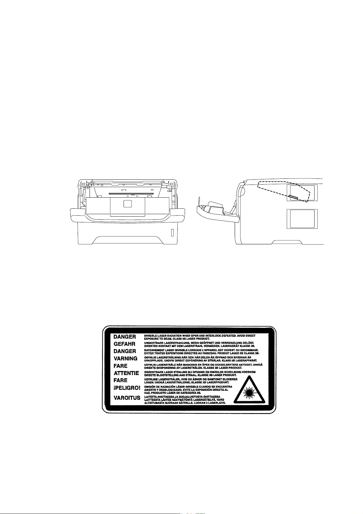
<Location of the laser beam window>
ADDITIONAL INFORMATION
When servicing the optical system of the printer, be careful not to place a screwdriver or
other reflective object in the path of the laser beam. Be sure to take off any personal
accessories such as watches and rings before working on the printer. A reflected beam,
though invisible, can permanently damage the eyes.
Since the beam is invisible, the following caution label is attached on the laser unit.
x Confidential
HL-5240/5250DN/5270DN/5280DW SERVICE MANUAL
DEFINITIONS OF WARNINGS, CAUTIONS AND NOTES
The following conventions are used in this service manual:
WARNING
Indicates warnings that must be observed to prevent possible personal injury.
CAUTION:
!
Indicates cautions that must be observed to service the printer properly or prevent damage
to the printer.
NOTE:
Indicates notes and useful tips to remember when servicing the printer.
**Listed below are the various kinds of “W ARNING” messages included in this manual.
WARNING
Always turn off the power switch and unplug the power cord from the power outlet
before accessing any parts inside the printer.
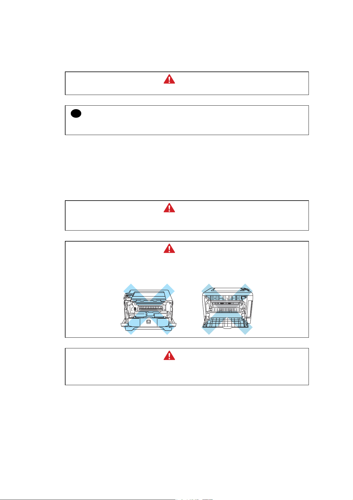
WARNING
Some parts inside the printer are extremely hot immediately after the printer is used.
When opening the front cover or back cover to access any parts inside the printer,
never touch the shaded parts shown in the following figures.
WARNING
If you analyze malfunctions with the power plug inserted into the power outlet,
special caution should be exercised even if the power switch is OFF because it is a
single pole switch.
xi Confidential

CHAPTER 1 GENERAL
1. FEATURES
This printer has the following features.
High Resolution and Fast Print Speed
True 600 x 600 dots, true 300 x 300 dots per inch (dpi), HQ1200 and 1200 x 1200 dpi for
graphics with microfine toner and up to 28 pages per minute (ppm) print speed for printing on
A4 size paper, and up to 30 pages per minute (ppm) print speed for Letter- size paper.
Versatile Paper Handling
The printer loads paper automatically from the paper tray. The paper tray can hold A4, letter,
B5 (ISO), B5 (JIS), A5, B6 (ISO), A6, Executive, Folio and Legal* size of paper. You can use
a variety of types and sizes of paper when printing from the Multi-purpose tray. Width: 69.9 to
215.9 mm (2.75 to 8.5 in) Length: 116 to 406.4 mm (4.57 to 16 in). A4, Letter, Legal sizes of
paper can be held when automatic duplex print. *Legal paper is not available in some regions.
HL-5240/5250DN/5270DN/5280DW SERVICE MANUAL
Front Operation
Basic operation of the printer can be controlled from the control panel.
Enhanced Printing Performance and User-Friendly Operation for Windows
The dedicated printer driver for Microsoft
Windows
2000/XP Home Edition/XP Professional/XP Professional x64 Edition are available
Windows 95/98/Me, Windows NT 4.0 and
on the CD-ROM supplied with your printer. You can easily install them into your Windows
system using our installer program. The driver supports our unique compression mode to
enhance printing speed in Windows
applications and allows you to choose various printer
settings including toner save mode, custom paper size, sleep mode, gray scale adjustment,
resolution, water mark and many layout functions. You can easily setup these print options
through the Printer Setup Menu.
Printer Status Monitor with Bi-directional Parallel Interface
The printer driver can monitor the status of your printer using bi-directional parallel
communications. IEEE-1284 bi-directional parallel printer cable is recommended.
The printer status monitor program can show the current status of your printer. The animated
dialog box appears on your computer screen to show the current printing process when
printing. If an error occurs, a dialog box will appear to let you know what to correct. If you
have turned on the Interactive Help (Windows only) you can get visual guidance on your PC
screen on the actions in the event of certain printer errors. The default setting is OFF.
Quick Print Setup
The Quick Print Setup is a convenient utility to allow you to make changes to frequently used
driver settings easily without having to open the printer properties selection box every time. It
is launched automatically when this printer driver is selected. You can change the settings by
clicking on the icon with the right mouse button. The default setting is OFF.
Enhanced Memory Management
The printer provides its own data compression technology in its printer hardware and the
supplied printer driver software, which can automatically compress graphic data and font data
efficiently into the printer’s memory. You can avoid memory errors and print most full pages
1200 dpi graphic and text data, including large fonts, with the standard printer memory.
1-1
Confidential

CHAPTER 1 GENERAL
USB Interface (for Windows
Professional X64 Edition, Mac OS
98/Me/2000/XP Home Edition/XP Professional/XP
9.1-9.2/ Mac OS
X 10.2.4 or greater)
The printer can be connected using the Universal Serial Bus (USB) interface to a PC or Mac
which has a USB interface. Drivers that allow you to use the USB port are provided on the CDROM supplied with the printer.
Popular Printer Emulation Support
These printers support the following printer emulation modes.
BR-Script 3, HP LaserJet (PCL6), Epson FX-850 and IBM Proprinter XL.
Environment-Friendly
<Economy Printing Mode (Toner Save Mode)>
This feature will cut your printing cost by saving toner. It is useful for obtaining draft copies for
proof-reading. You can select the toner saving economy mode through the Windows
printer
driver supplied with your printer.
<Sleep Mode (Power Save Mode)>
Sleep mode automatically reduces power consumption when the printer is not in use for a
certain period of time. The printer consumes less than 8.5W when in sleep mode.
<Low Running Cost>
Since the toner cartridge is separate from the drum unit, you need to replace only the toner
cartridge after printing around 3,500 (Standard cartridge) pages or 7,000 (High yield cartridge)
at 5% coverage for A4 paper for the standard cartridge, which is both cost effective and
ecologically friendly.
Bar Code Print
The printer can print the following 11 types of bar codes
• Code 39 • US-PostNet • EAN-8
• Code 128 • ISBN • EAN-13
• Interleaved 2 of 5 • UPC-A • EAN-128
• Codabar • UPC-E
Network Feature (for HL-5250DN/5270DN/5280DW)
The Brother printer has built in multi protocol network capability as standard. This allows
multiple host computers to share the printer on a 10/100Mb wired Ethernet or IEEE
802.11b/802.11g wireless Ethernet network. Any users can print their jobs as if the printer was
directly connected to their computer. Users on Windows
Windows
to 9.2, Mac OS
®
2000/XP Home Edition/XP Professional/XP Professional x64 Edition, Mac OS® 9.1
®
X 10.2.4 or greater simultaneously can access this printer. For further
®
95/98/Me, Windows® NT4.0,
information, see the Network User’s Guide supplied with the printer. The wireless network
function is supported by the HL-5280DW only.
1-2
Confidential
2. PARTS NAMES AND FUNCTIONS
A
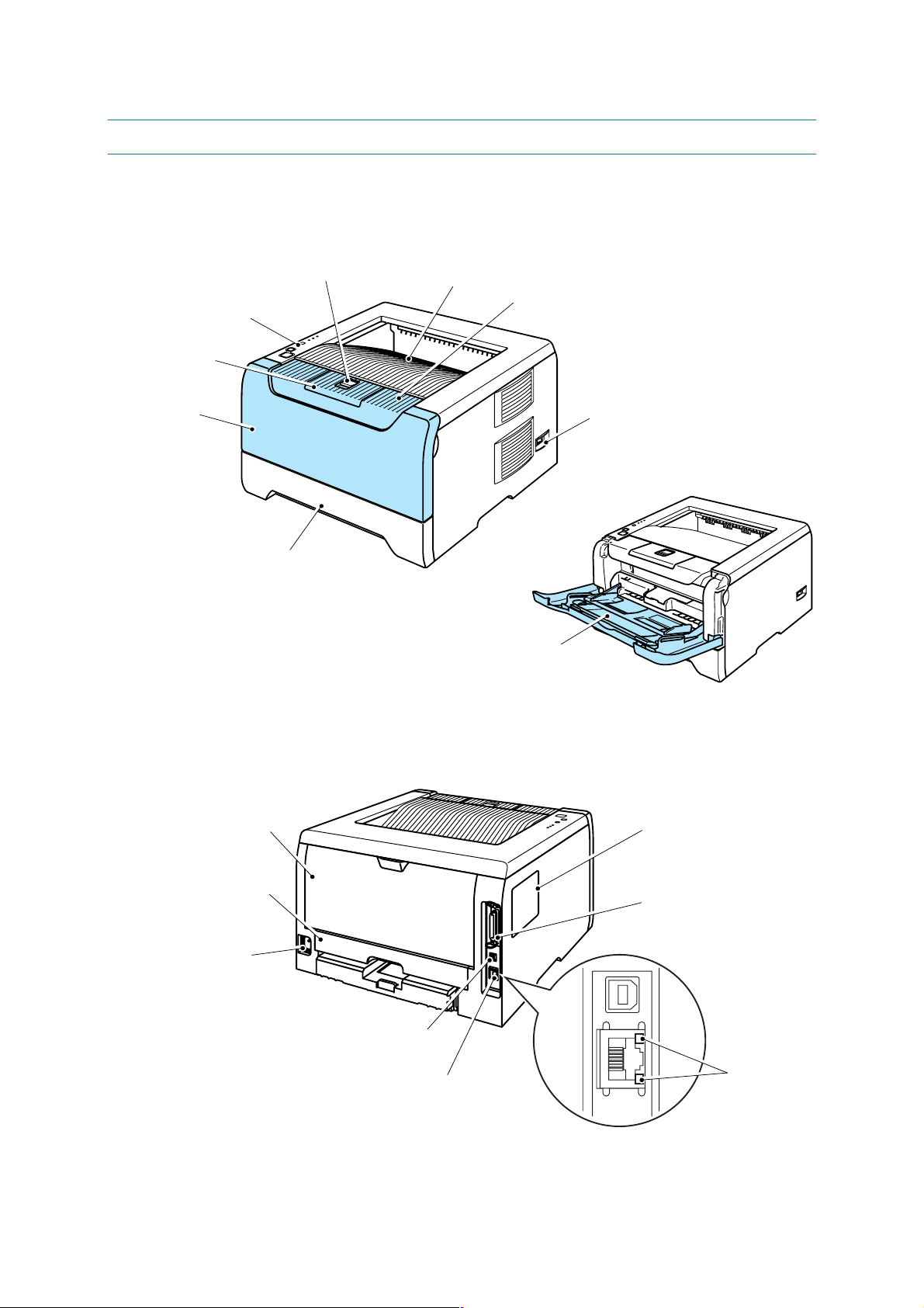
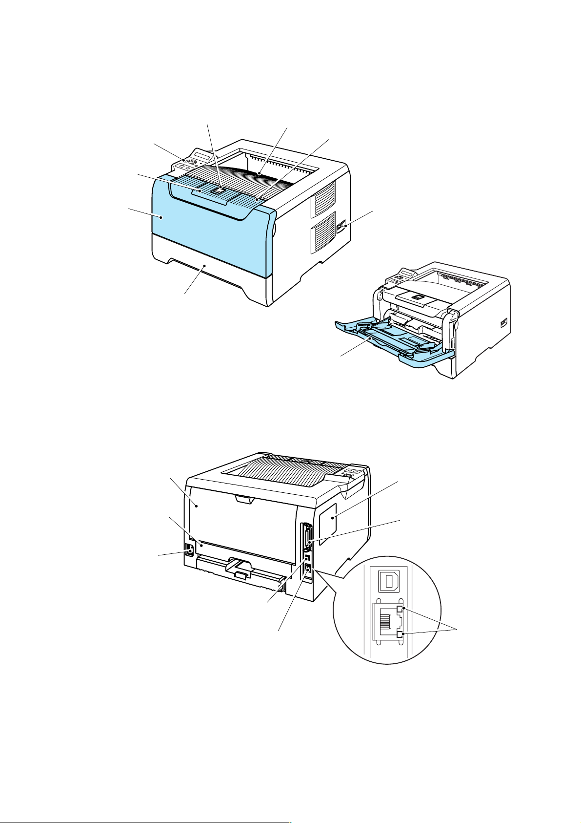
2.1 Overview
(HL-5240/5250DN)
<Front View>
HL-5240/5250DN/5270DN/5280DW SERVICE MANUAL
Front cover release button
Control panel
Face-down output tray
support flap (support flap)
MP tray cover ASSY
Paper tray
Face-down output tray
Multi-purpose tray (MP tray)
Fig. 1-1
Front cover
Power switch
<Rear View>
Back cover
Duplex tray
(For HL-5250DN)
C power connector
USB interface connector
10/100BASE-TX port
(For HL-5250DN)
*The printer illustration is based on HL-5250DN.
Fig. 1-2
DIMM cover
Parallel interface connector
Network status LEDs
(Light emitting diodes)
(For HL-5250DN)
1-3
Confidential
CHAPTER 1 GENERAL
A
(HL-5270DN/5280DW)
<Front View>
Control panel
Face-down output tray
support flap (support flap)
MP tray cover ASSY
Front cover release button
Paper tray
Face-down output tray
Front cover
Power switch
Multi-purpose tray (MP tray)
Fig. 1-3
<Rear View>
Back cover
Duplex tray
C power connector
USB interface connector
10/100BASE-TX port
DIMM cover
Parallel interface connector
LEDs
(Light emitting diodes)
Fig. 1-4
1-4
Confidential
HL-5240/5250DN/5270DN/5280DW SERVICE MANUAL
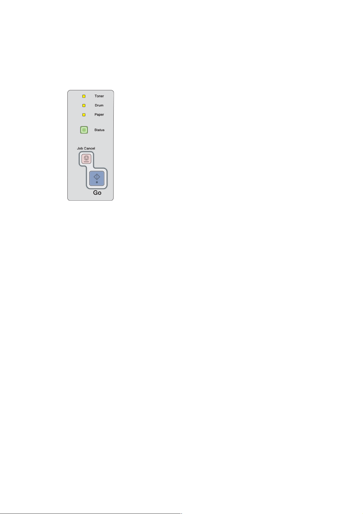
2.2 Control Panel
(HL-5240/5250DN)
There are the four Light Emitting Diodes (LEDs) (Toner, Drum, Paper and Status) and two
control buttons (Go and Job Cancel) on the control panel.
1. Toner
LED indicates when the Toner is low or at the end of its life.
2. Drum
LED indicates when the Drum is nearing the end of its life.
3. Paper
LED indicates when the paper tray is empty or there is a paper
jam.
4. Status
LED will flash and change color depending on the printer status.
5. Job Cancel button
will stops and cancels the print operation in progress.
6. Go button
Wake-up / Error recovery / Form feed / Reprint
Fig. 1-5
1-5
Confidential
CHAPTER 1 GENERAL
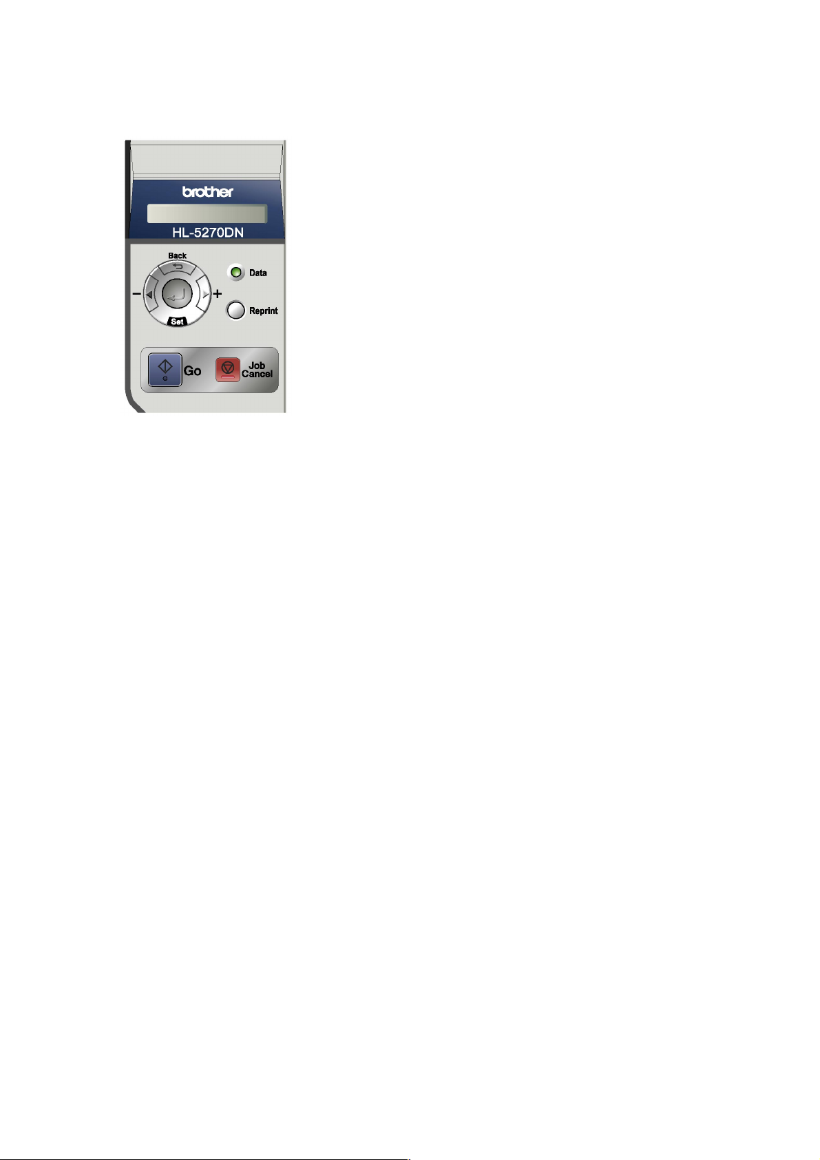
(HL-5270DN/5280DW)
Fig. 1-6
1. LCD
• Off: The printer is off or in sleep status.
• Green (General): Ready to print.
Printing
Warming up
Job canceling
• Red (Error): There is a problem with the printer.
• Orange (Setting): The printer is offline.
Choosing a menu
Setting number of reprints.
Pause
2. Data LED: Orange
• On: Data is in the printer memory.
• Blinking: Receiving or processing data.
• Off: No remaining data in the memory.
3. Go button
Exit from the control panel menu and reprint setting.
Clear error messages.
Pause and Continue printing.
4. Job Cancel button
Stop and cancel the printing operation in progress.
5. Reprint button
Choose the reprint menu and the number of extra copies
(1-999).
Please enhance the RAMDISK size when you want to use
the Reprint functions.
6. Menu buttons
• +: Move forward through menus.
Move forward through the available options.
• -: Move backward through menus.
Move forward through the available options.
• Set: Choose the control panel menu.
Set the chosen menus and settings.
• Back: Go back one level in the menu structure.
1-6
Confidential

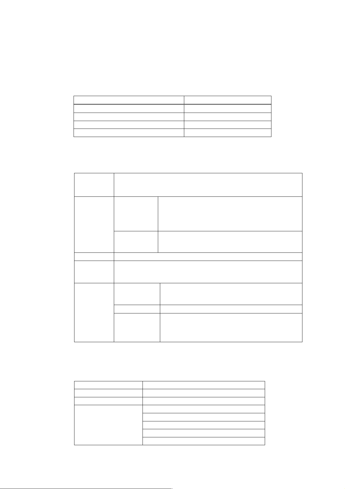
3. SPECIFICATIONS
3.1 Printing
Print method Electrophotography by semiconductor laser beam scanning
Laser Wavelength: 770 - 810nm
HL-5240/5250DN/5270DN/5280DW SERVICE MANUAL
Output: 5mW max
Laser class: Class B
Resolution <Windows
Windows
Edition and Mac OS
95, WindowsNT
XP Home Edition/XP Professional/XP Professional x64
>
4.0, Windows
98/Me, Windows
2000,
1200 dpi*/ HQ1200/ 600dpi/ 300dpi
<DOS>
600dpi
<Linux>
600dpi/ 300dpi
* When you choose the higher print quality setting, the print speed will
be slower.
Print quality Normal printing mode
Economy printing mode (Toner saving mode)
Print speed Normal
Up to 28 pages/minute (A4 size paper)
Up to 30 pages/minute (Letter-size paper)
Warm-up Less than 18 seconds at 23°C (73.4°F)
First print Less than 8.5 seconds when the printer is in the ready state.
(when loading A4 or Letter-size paper from the standard paper tray)
Consumables <Toner cartridge>
Life expectancy:
Standard 3,500 pages / cartridge
High yield 7,000 pages / cartridge
* when printing A4 or Letter-size paper at 5% print coverage.
<Drum unit>
Life expectancy: 25,000 pages/ drum unit (1 page/ job)
* when printing A4 or Letter-size paper at 5% print coverage.
NOTE:
Print speed varies depending on the paper size or media type. For details, refer to 3.8 ‘Print
Speeds with Various Settings’ in this Chapter.
1-7
Confidential

CHAPTER 1 GENERAL
3.2 Functions
<Controller>
Processor 266MHz
Emulation BR-Script 3 (PostScript
Memory <Standard>
3TM), HP LaserJet (PCL6), Epson FX-850 and
IBM Proprinter XL
16 MB (HL-5240) 32MB (HL-5250DN/5270DN/5280DW)
<Option>
DIMM
(HL-5240)
The HL-5240 printer has 16 MB of standard memory and one slot for
optional memory expansion. You can expand the memory up to 528
MB by installing dual in-line memory modules (DIMMs).
(HL-5250DN/5270DN/5280DW)
The HL-5250DN/5270DN/5280DW printer has 32 MB of standard
memory and one slot for optional memory expansion. You can
expand the memory up to 544 MB by installing dual in-line memory
modules (DIMMs).
“DIMM types”
You can install the following DIMMs:
• 128 MB Buffalo Technology VN133-D128/ VN133-X128
• 256MB Buffalo Technology VN133-D256
• 512MB Buffalo Technology VN133-D512
• 64 MB TechWorks 12165-0004
• 128 MB TechWorks 12462-0001
• 256MB TechWorks 12485-0001
• 512MB TechWorks 12475-0001
In general, the DIMM must have the following specifications:
Type: 144 pin and 64 bit output
CAS latency: 2
Clock frequency: 100 MHz or more
Capacity: 64, 128, 256 or 512 MB
Height: 31.75 mm (1.25 in.)
Dram Type: SDRAM 2 Bank
SDRAM can be used.
NOTE:
There might be some DIMMs that will not work with the printer.
Interface Standard:
HL-5240 HL-5250DN/5270DN HL-5280DW
Hi-Speed USB 2.0
IEEE 1284 Parallel
Option:
HL-5240 HL-5250DN/5270DN HL-5280DW
10/100 BASE-TX
Ethernet (NC-2100p)
1-8
Hi-Speed USB 2.0
IEEE 1284 Parallel
10/100 BASE-TX
N/A N/A
Hi-Speed USB 2.0
IEEE 1284 Parallel
10/100 BASE-TX
Wireless LAN
IEEE802.11 b/g
Confidential

HL-5240/5250DN/5270DN/5280DW SERVICE MANUAL
Resident Fonts (HL-5240/5250DN)
66 scalable fonts, 12 bitmap fonts, 11 bar codes;
Code39, Interleaved 2 of 5, EAN-8, EAN-13, UPC-A, EAN-128,
Codabar, FIM (US-PostNet), ISBN, Code128
(HL-5270DN/5280DW)
<PCL>
66 scalable fonts, 12 bitmap fonts, 11 bar codes;
Code39, Interleaved 2 of 5, EAN-8, EAN-13, UPC-A, EAN-128,
Codabar, FIM (US-PostNet), ISBN, Code128
<PostScript
3TM>
66 fonts
Option Font (HL-5240/5250DN/5270DN/5280DW)
BT-1000 (Agfa Barcode Font)
<Software>
Printer driver <Windows
• PCL Driver for Windows
>
Windows
2000 and Windows XP Home Edition/XP
95/98/Me, Windows NT 4.0,
Professional/XP Professional x64 Edition *
* Download the printer driver for Windows
Edition from http://solutions.brother.com
• Generic PCL Driver for Windows NT
Windows
XP Home Edition/XP Professional/XP Professional
4.0, Windows 2000 and
x64 Edition
• BR-Script 3 (PPD file) for Windows
<Macintosh
>
• Brother Laser Driver for Mac OS
95/98/Me, Windows NT 4.0
9.1 to 9.2 and Mac OS X
10.2.4 or greater
• BR-Script 3 (PPD file) for Mac OS
9.1 to 9.2 and Mac OS X
10.2.4 or greater
XP Professional x64
<Linux*>
• LPR Driver for Linux
• CUPS driver for Linux
* Download the printer driver for Linux from
http://solutions.brother.com
1-9
Confidential

CHAPTER 1 GENERAL
Utilities (HL-5240)
System Requirements
Computer Platform & Operating
System Version
Windows
Macintosh
Interactive Help*
(HL-5250DN/5270DN/5280DW)
Interactive Help*, Driver Deployment Wizard**
* Interactive Help: Instructional animations for problem solving.
** The Driver Deployment Wizard automates the installation of a
printer in a peer-to-peer network.
Processor Speed Minimum
RAM
95*1, 98, 98SE 486/66 MHz 8 MB 16 MB 40 MB
NTWorkstation 4.0 *1Intel Pentium 75 MHz 16 MB 32 MB 50 MB
2000 Professional Intel Pentium 133 MHz 64 MB 128 MB 50 MB
Me Intel Pentium 150 MHz 32 MB 64 MB 50 MB
XP Home Edition
Pentium 300 MHz 128 MB 128 MB 50 MB
Intel
XP Professional
XP Professional x64
Edition
*2
AMD Opteron
AMD Athlon
Intel
XeonTM with Intel
EM64T
X Pentium with 4 Intel
Intel
TM
TM
256 MB 256 MB 50 MB
64
EM64T
OS 9.1-9.2 32 MB 64 MB 50 MB Apple
*3
Mac OS
X10.2.4 or
All base models meet
minimum requirements
128 MB 160 MB 50 MB
greater
Recom-
mended
RAM
Available
Hard
Disk
Space
*1 USB is not supported under Windows 95 or Windows NT 4.0.
*2 Download the printer driver for Windows
http://solutions.brother.com
XP Professional x64 Edition from
*3 Power Macintosh with an Apple original pre-installed USB port.
1-10
Confidential

3.3 Electronics and Mechanics
Power source U.S.A. and Canada: AC 110 to 120V, 50 Hz/60 Hz
Europe and Australia: AC 220 to 240V, 50 Hz/60 Hz
Power consumption Printing: Average 610 W at 25°C (77°F)
Standing by: Average 80 W at 25°C (77°F)
Sleep: Average 8 W (HL-5240)
Noise level <Sound pressure>
Printing: 53dB (A)
Standing by: 27dB (A)
<Sound power>
Printing: LWAd=6.4 Bell (A)
Standing by: 4.0 Bell (A)
Temperature Operating: 10 to 32.5°C (50 to 90.5°F)
Non operating: 0 to 40°C (38 to 104°F)
Storage: -20 to 40°C (-4 to 104°F)
HL-5240/5250DN/5270DN/5280DW SERVICE MANUAL
Average 620 W at 25°C (77°F) (HL-5280DW)
Average 9 W (HL-5250DN/5270DN)
Average 12 W (HL-5280DW)
Humidity Operating: 20 to 80% (non condensing)
Storage: 10 to 85% (non condensing)
Dimensions (HL-5240/5250DN) <W x D x H>
371 x 384 x 246 mm (14.6 x 15.1 x 9.7 inches)
(HL-5270DN/5280DW) <W x D x H>
393 x 384 x 259 mm (15.5 x 15.1 x 10.2 inches)
Weight (HL-5240)
Approximately 8.3 kg (18.3 lb.), not including the drum unit and toner
cartridge.
Approximately 9.5 kg (20.9 lb.) including the drum unit and toner
cartridge.
(HL-5250DN)
Approximately 8.6 kg (19.0 lb.), not including the drum unit and toner
cartridge.
Approximately 9.8 kg (21.6 lb.) including the drum unit and toner
cartridge.
(HL-5270DN/5280DW)
Approximately 8.8 kg (19.4 lb.), not including the drum unit and toner
cartridge.
Approximately 10.0 kg (22.0 lb.) including the drum unit and toner
cartridge
NOTE:
The power consumption figure quoted for sleep mode is when the fan has stopped.
1-11
Confidential
CHAPTER 1 GENERAL
3.4 Service Information
These are key service information to maintain the product.
Machine life: 200,000 pages/ 5 years
MTBF (Meantime between failure): Up to 4000 hours
MTTR (Meantime to repair): Average 30 minutes
Monthly volume: 20,000 pages
Periodical replacement parts:
Fuser Unit 100,000 pages
Separator pad holder assembly 100,000 pages
Pick up roller assembly 100,000 pages
Laser Unit 100,000 pages
* As for periodical replacement parts, refer to Chapter 3.
3.5 Network Connectivity
<Print server>
• NC-6400h (HL-5250DN/5270DN/5280DW)
Operating
system
support
Protocol
support
Network type 10/100BASE-TX Ethernet network
Network
printing
Management
utilities
NOTE:
NC-6400h is a network controller of the printer built-in type.
Parts Approximate Life
Windows
Edition/XP Professional/XP Professional x64 Edition,
Mac OS
95/98/Me, Windows NT 4.0, Windows 2000/XP Home
9.1 to 9.2, Mac OS
X 10.2.4 or greater
TCP/IP: IPv4 APR, RARP, BOOTP, DHCP, APIPA (Auto IP),
WINS, NetBIOS name resolution, DNS Resolver,
mDNS. LPR/LPD, Custom Raw Port/Port9100, SMB
Print, IPP, FTP Server, Telnet, SNMP, HTTP, TFTP,
SMTP Client
TCP/IP: IPv6 NDP, DNS Resolver, mDNS, LPR/LPD, Custom Raw
Port/Port9100, IPP, FTP Server, Telnet, SNMP,
HTTP, TFTP, SMTP Client
Windows
Windows
x64 Edition TCP/IP printing, Macintosh
BRAdmin
Professional
utility
BRAdmin Light
Web BRAdmin
95/98/Me Peer-to-Peer printing, Windows NT 4.0 and
2000/XP Home Edition/XP Professional/XP Professional
Windows
95/98/Me, Windows NT 4.0, Windows
printing
2000/XP Home Edition/XP Professional/XP
Professional x64 Edition
Mac OS
Windows
Server, Windows
X 10.2.4 or greater
2000 Professional / Server / Advanced
XP Home Edition/XP
Professional/XP Professional x64 Edition
Professional
• NC-2100p (HL-5240) (Option)
An optional network print server (NC-2100p) allows you to connect to your network
through the parallel interface.
Network interface 10/100BASE-TX Ethernet
Printer interface Parallel
Support protocol TCP/IP, NetBEUI
Management features
Embedded web server support
SNMP / MIB support
TELNET remote console
BRAdmin Professional compatible
Flash memory for easy updating of firmware
1-12
Confidential

<Ethernet wireless network>
HL-5240/5250DN/5270DN/5280DW SERVICE MANUAL
Network node type NC-7200w
Operating system
support
Protocol support
Windows
Mac OS
TCP/IP: IPv4
98/Me, Windows NT 4.0, Windows 2000/XP
X 10.2.4 or greater
APR, RARP, BOOTP, DHCP, APIPA (Auto IP),
WINS, NetBIOS name resolution, DNS
Resolver, mDNS, LPR/LPD, Custom Raw
Port/Port9100, SMB Print, IPP, FTP Server,
Telnet, SNMP, HTTP, TFTP, SMTP Client
TCP/IP: IPv6
NDP, DNS Resolver, mDNS, LPR/LPD, Custom
Raw Port/Port9100, IPP, FTP Server, Telnet,
SNMP, HTTP, TFTP, SMTP Client
Network type IEEE 802.11b/g wireless
Frequency 2412-2472 MHz
RF channels
USA/Canada 1-11
Europe/Oceania 1-13
Japan 1-14
Communication
Infrastructure, Ad-hoc 802.11
mode
802.11b 11/5.5/2/1 Mbps Data rates
802.11g 54/48/36/24/18/12/9/6 Mbps
Link distance 70 m (233 ft.) at lowest data rate (The distance rate will vary upon
environment and other equipment location.)
Network security SSID/ESSID, 128 (104) / 64 (40) bit WEP, WPA-PSK (TKIP/AES),
LEAP
Network printing
Computer
requirements
(for drivers,
BRAdmin
Professional,
Peer-to-Peer
software, etc.)
Macintosh
connection
Windows
Windows NT
Macintosh
Processor Minimum
Speed
Minimum RAM
Recommended
RAM
Computer
Processor Minimum
95/98/Me Peer-to-Peer printing
4.0 and Windows 2000/XP TCP/IP printing
printing (Mac OS 10.2.4 or greater supporting TCP/IP)
Pentium
Windows NT
24MB for Windows
32MB for Windows
64MB for Windows
32MB for Windows
64MB for Windows
128MB for Windows
II or equivalent for Windows 98/Me,
4.0, Windows 2000/XP
98/Me
2000
XP
98/98SE/Me
2000
XP
Wireless (AirPort) ready Power Macintosh
All base models meet minimum requirements
Speed
Minimum RAM
Recommended
128MB for Mac OS
160MB for Mac OS
X 10.2.4 or greater
X 10.2.4 or greater
RAM
Management
utilities
BRAdmin
Professional
BRAdmin Light
Web BRAdmin
Windows
2000/XP
Mac OS
*1
Windows
Advanced Server, Windows
98/Me, Windows NT 4.0, Windows
X 10.2.4 or greater
2000 Professional / Server /
XP Professional
*1: Web BRAdmin are available as a download from http://solutions.brother.com.
1-13
Confidential
CHAPTER 1 GENERAL
3.6 Paper
3.6.1 Paper handling
Paper Input*
Multi-purpose tray 50 sheets
Paper tray (Standard) 250 sheets
Lower tray (Option) 250 sheets
* Calculated with 80 g/m2 (21 lb) paper.
Paper Output*
Face-down 150 sheets
* Calculated with 80 g/m2 (21 lb) paper.
Duplex
Manual Duplex Yes
Automatic Duplex N/A Yes
3.6.2 Media specifications
(1) Media types
The printer loads paper from the installed paper tray or the multi-purpose tray. The
feedable media type and size are different depending on the paper tray installed. The
names for the paper trays in the printer driver and this guides are as follows;
All models
All models
HL-5240 HL-5250DN/ 5270DN/ 5280DW
Paper tray Tray 1
Multi-purpose tray MP Tray
Optional lower tray unit Tray 2/ Tray 3
Duplex tray for automatic duplex
DX
printing (for HL5250DN/5270DN/5280DW)
The table in the next page shows the feedable media of each paper tray described above.
1-14
Confidential
HL-5240/5250DN/5270DN/5280DW SERVICE MANUAL
Plain paper
75 g/m2 to 105
2
g/m
(20 to 28 lbs.)
Recycled
paper
Bond paper
Rough paper-
60 g/m2 to 161
2
g/m
(16 to 43 lbs.)
Thin paper
60 g/m2 to 75
2
g/m
(16 to 20 lbs.)
Thick paper
105 g/m2 to 161
2
g/m
(28 to 43 lbs.)
Transparency
Tray 1/2/3 MP Tray DX
Yes Yes Yes
Yes Yes Yes
Yes
60 g/m2 to 105
2
g/m
(16 to 28 lbs.)
Yes
2
60 g/m
g/m
to 161
2
(16 to 43 lbs.)
N/A
Yes Yes Yes
N/A Yes N/A
Yes
Up to 10 sheets
A4 or Letter **
Yes
Up to 10 sheets
A4 or Letter
N/A
Choose the
media type from
the printer driver
Plain paper
Recycled paper
Bond paper
Thin paper
Thick Paper or
Thicker Paper
Transparencies
Labels
Envelopes
N/A Yes
A4 or Letter
N/A Yes N/A
N/A
Thicker Paper
Envelopes,
Env. Thin,
Env. Thick
* Up to 10 sheets
** Not available for the optional Tray 2/3.
(2) Media size
MP Tray Tray 1 (Standard)
Width:
69.9 to 215.9 mm
(2.75 to 8.5 in.)
Length:
A4, Letter, Legal*,
B5 (ISO),
Excutive, A5, A6,
B6 (ISO)
Tray 2, Tray3
(Option)
A4, Letter, Legal*,
B5 (ISO),
Excutive, A5,
B6 (ISO)
DX
A4, Letter, Legal*
116 to 406.4 mm
(4.57 to 16 in.)
* Legal size paper is not available in some regions outside the USA and Canada.
1-15
Confidential
CHAPTER 1 GENERAL
(3) Media weights
Tray 1 MP Tray DX
Tray 2/3
Lower tray unit
(Option) (LT-5300)
60 to 105 g/m2
(16 to 28 lb.)
60 to 161 g/m2
(16 to 43 lb.)
60 to 105 g/m2
(16 to 28 lb.)
60 to 105 g/m2
(16 to 28 lb.)
(4) Recommended paper
Plain paper
Xerox Premier 80 g/m
Xerox Business 80 g/m
Europe USA
2
2
Xerox 4200DP 20lb
Hammermill Laser Paper 24lb
M-real DATACOPY 80 g/m2
Recycled paper
Transparency
Label
Xerox Recycled Supreme N/A
3M CG3300 3M CG 3300
Avery laser label L7163 Avery laser label #5160
* This printer can use recycled paper that meets the DIN 19309 specification.
(5) Moisture content
Moisture content
4% to 6% by weight
CAUTION:
!
When you are choosing print media, be sure to follow the information given below to prevent
any paper jams, print quality problems or printer damage;
• It is recommended to use long-grained paper for the best print quality. If short-grained
paper is being used, it might be the cause of paper jams.
• Use neutral paper. Do not use acid paper to avoid any damage to the drum unit.
• Avoid using coated paper such as vinyl coated paper.
• Avoid using preprinted or highly textured paper.
• It is recommended to use labels or transparencies which are designed for use in laser
printers.
• Avoid feeding labels with the carrier sheet exposed, or the printer will be damaged.
• Before loading paper with holes such as organizer sheets, be sure to fan the stack well.
• Do not use organizer sheets that are stuck together. The glue that is used might caused
damaged to the printer.
• When printing on the back of pre-printed paper, if the paper is curled, be sure to straighten
the paper as much as possible.
Different types of paper should not be loaded at the same time in the paper tray to avoid any
paper jams or misfeeds.
1-16
Confidential
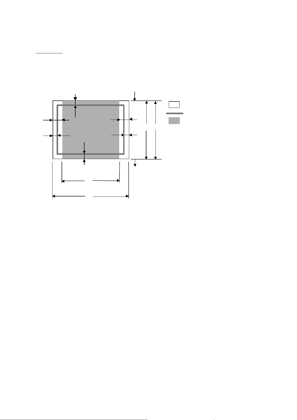
3.7 Printable Area
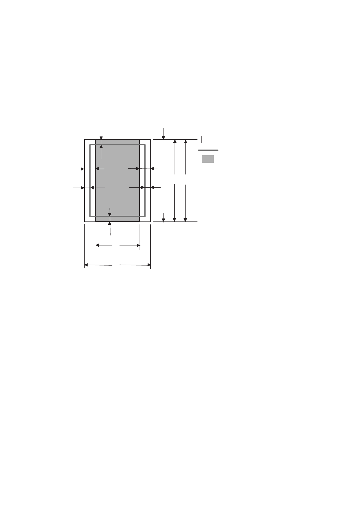
3.7.1 PCL5e/EPSON/IBM emulation
When using PCL emulation, the edges of the paper that cannot be printed on are shown
below.
Portrait
HL-5240/5250DN/5270DN/5280DW SERVICE MANUAL
E
G
NOTE:
G
G
C
A
F
Physical page
Printable area
Logical page
E
B
D
G
F
B Physical page length
D
F
Maximum logical page length
Distance from edge of physical page to
edge of logical page
• “Logical page” shows the printable area for a PCL driver.
• “Printable area” shows mechanical printable area of the machine.
• Therefore, the machine can only print within the shaded area when you use a PCL driver.
1-17
Confidential

CHAPTER 1 GENERAL
The table below shows the printable areas when printing on Portrait for each paper size.
Size A B C D E F G
Letter
Legal
Folio
Executive
A 4
A 5
A 6
B 5 (JIS)
B 5 (ISO)
B 6 (ISO)
COM10
MONARCH
C 5
DL
DL L
NOTE:
• The paper sizes indicated here should confirm to the nominal dimensions specified by JIS
except B5 (ISO), B6 (ISO).
• The dot size is based on 300 dpi resolution.
215.9 mm
8.5”
(2,550 dots)
215.9 mm
8.5”
(2,550 dots)
215.9 mm
8.5”
(2,550 dots)
184.15 mm
7.25”
(2,175 dots)
210.0 mm
8.27”
(2,480 dots)
148.5 mm
5.85”
(1,754 dots)
105.0 mm
4.13”
(1,240 dots)
182.0 mm
7.1”
(2,130 dots)
176.0 mm
6.93”
(2,078 dots)
125.0 mm
4.92”
(1,476 dots)
104.78 mm
4.125”
(1,237 dots)
98.43 mm
3.875”
(1,162 dots)
162.0 mm
6.38”
(1,913 dots)
110.0 mm
4.33”
(1,299 dots)
220.0 mm
8.66”
(2,598 dots)
279.4 mm
11.0”
(3,300 dots)
355.6 mm
14.0”
(4,200 dots)
330.2mm
13.0”
(3,900 dots)
266.7 mm
10.5”
(3,150 dots)
297.0 mm
11.69”
(3,507 dots)
210.0 mm
8.27”
(2,480 dots)
148.5 mm
5.85”
(1,754 dots)
257.0 mm
10.11”
(3,033 dots)
250.0 mm
9.84”
(2,952 dots)
176.0 mm
6.93”
(2,078 dots)
241.3 mm
9.5”
(2,850 dots)
190.5 mm
7.5”
(2,250 dots)
229.0 mm
9.01”
(2,704 dots)
220.0 mm
8.66”
(2,598 dots)
110.0 mm
4.33”
(1.299 dots)
203.2 mm
8.0”
(2,400 dots)
203.2 mm
8.0”
(2,400 dots)
203.2 mm
8.0”
(2,400 dots)
175.7 mm
6.92”
(2,025 dots)
198.0 mm
7.79”
(2,338 dots)
136.5 mm
5.37”
(1,612 dots)
93.0 mm
3.66”
(1,098 dots)
170.0 mm
6.69”
(2,007 dots)
164.0 mm
6.46”
(1,936 dots)
164.0 mm
4.44”
(1,334 dots)
92.11 mm
3.63”
(1,087 dots)
85.7 mm
3.37”
(1,012 dots)
150.0 mm
5.9”
(1,771 dots)
98.0 mm
3.86”
(1,157 dots)
207.4 mm
8.17”
(2,450 dots)
279.4 mm
11.0”
(3,300 dots)
355.6 mm
14.0”
(4,200 dots)
330.2mm
13.0”
(3,900 dots)
266.7 mm
10.5”
(3,150 dots)
297.0 mm
11.69”
(3,507 dots)
210.0 mm
8.27”
(2,480 dots)
148.5 mm
5.85”
(1,754 dots)
257.0 mm
10.11”
(3,033 dots)
250.0 mm
9.84”
(2,952 dots)
176.0 mm
6.93”
(2.078 dots)
241.3 mm
9.5”
(2,850 dots)
190.5 mm
7.5”
(2,250 dots)
229.0 mm
9.01”
(2,704 dots)
220.0 mm
8.66”
(2,598 dots)
110.0 mm
4.33”
(1.299 dots)
6.35 mm
0.25”
(75 dots)
Ç
Ç
6.35 mm
0.25”
(75 dots)
6.01 mm
0.24”
(71 dots)
Ç
Ç
Ç
Ç
Ç
6.35 mm
0.25”
(75 dots)
Ç
6.01 mm
0.24”
(71 dots)
Ç
6.27 mm
0.25”
(74 dots)
0 mm
0 mm
0 mm
0 mm
0 mm
0 mm
0 mm
0 mm
0 mm
0 mm
0 mm
0 mm
0 mm
0 mm
0 mm
4.2 mm
0.16”
(50 dots)
4.2 mm
0.16”
(50 dots)
4.2 mm
0.16”
(50 dots)
4.2 mm
0.16”
(50 dots)
4.2 mm
0.16”
(50 dots)
4.2 mm
0.16”
(50 dots)
4.2 mm
0.16”
(50 dots)
4.2 mm
0.16”
(50 dots)
4.2 mm
0.16”
(50 dots)
4.2 mm
0.16”
(50 dots)
4.2 mm
0.16”
(50 dots)
4.2 mm
0.16”
(50 dots)
4.2 mm
0.16”
(50 dots)
4.2 mm
0.16”
(50 dots)
6.27 mm
0.25”
(74 dots)
1-18
Confidential
Landscape
HL-5240/5250DN/5270DN/5280DW SERVICE MANUAL
E
G
NOTE:
G
G
F
Physical page
Printable area
E
D
B
G
B Physical page length
D Maximum logical page length
F Distance from edge of physical
page to edge of logical page
F
Logical page
C
A
• “Logical page” shows the printable area for a PCL driver.
• “Printable area” shows mechanical printable area of the machine.
• Therefore, the machine can only print within the shaded area when you use a PCL driver.
1-19
Confidential

CHAPTER 1 GENERAL
The table below shows the printable areas when printing on Landscape for each paper size.
Size A B C D E F G
Letter
Legal
Folio
Executive
A 4
A 5
A 6
B 5 (JIS)
B 5 (ISO)
B 6 (ISO)
COM10
MONARCH
C 5
DL
DL L
NOTE:
• The paper sizes indicated here should confirm to the nominal dimensions specified by JIS
except B5 (ISO), B6 (ISO).
• The dot size is based on 300 dpi resolution.
279.4 mm
11.0”
(3,300 dots)
355.6 mm
14.0”
(4,200 dots)
330.2mm
13.0”
(3,900 dots)
266.7 mm
10.5”
(3,150 dots)
297.0 mm
11.69”
(3,507 dots)
210.0 mm
8.27”
(2,480 dots)
148.5 mm
5.85”
(1,754 dots)
257.0 mm
10.11”
(3,033 dots)
250.0 mm
9.84”
(2,952 dots)
176.0 mm
6.93”
(2,078 dots)
241.3 mm
9.5”
(2,850 dots)
190.5 mm
7.5”
(2,250 dots)
229 mm
9.01”
(2,704 dots)
220 mm
8.66”
(2,598 dots)
110 mm
4.33”
(1,299 dots)
215.9 mm
8.5”
(2,550 dots)
215.9 mm
8.5”
(2,550 dots)
215.9 mm
8.5”
(2,550 dots)
184.15 mm
7.25”
(2,175 dots)
210.0 mm
8.27”
(2,480 dots)
148.5 mm
5.85”
(1,754 dots)
105.0 mm
4.13”
(1,240 dots)
182.0 mm
7.1”
(2,130 dots)
176.0 mm
6.93”
(2,078 dots)
125.0 mm
4.92”
(1,476 dots)
104.78 mm
4.125”
(1,237 dots)
98.43 mm
3.875”
(1,162 dots)
162 mm
6.38”
(1,913 dots)
110 mm
4.33”
(1,299 dots)
220 mm
8.66”
(2,598 dots)
269.3 mm
10.6”
(3,180 dots)
345.5 mm
13.6”
(4,080 dots)
320.0mm
12.6”
(3,780 dots)
256.6 mm
10.1”
(3,030 dots)
287.0 mm
11.2”
(3,389 dots)
200.0mm
7.87”
(2,362 dots)
138.5 mm
5.45”
(1,636 dots)
247.0 mm
9.72”
(2,916 dots)
240.0 mm
9.44”
(2,834 dots)
166.4 mm
6.55”
(1,960 dots)
231.1 mm
9.1”
(2,730 dots)
180.4 mm
7.1”
(2,130 dots)
219.0 mm
8.62”
(2,586 dots)
210.0 mm
8.26”
(2,480 dots)
97.5 mm
3.84”
(1,151 dots)
215.9 mm
8.5”
(2,550 dots)
215.9 mm
8.5”
(2,550 dots)
215.9 mm
8.5”
(2,550 dots)
184.15 mm
7.25”
(2,175 dots)
210.0 mm
8.27”
(2,480 dots)
148.5 mm
5.85”
(1,754 dots)
105.0 mm
4.13”
(1,240 dots)
182.0 mm
7.1”
(2,130 dots)
176.0 mm
6.93”
(2,078 dots)
125.0 mm
4.92”
(1,476 dots)
104.78 mm
4.125”
(1,237 dots)
98.43 mm
3.875”
(1,162 dots)
162 mm
6.38”
(1,913 dots)
110 mm
4.33”
(1,299 dots)
220 mm
8.66”
(2,598 dots)
5.0 mm
0.2”
(60 dots)
Ç
Ç
5.0 mm
0.2”
(60 dots)
4.8 mm
0.19”
(59 dots)
Ç
Ç
Ç
Ç
Ç
5.0 mm
0.2”
(60 dots)
Ç
4.8 mm
0.19”
(59 dots)
Ç
6.27 mm
0.25”
(74 dots)
0 mm
0 mm
0 mm
0 mm
0 mm
0 mm
0 mm
0 mm
0 mm
0 mm
0 mm
0 mm
0 mm
0 mm
0 mm
4.2 mm
0.16”
(50 dots)
4.2 mm
0.16”
(50 dots)
4.2 mm
0.16”
(50 dots)
4.2 mm
0.16”
(50 dots)
4.2 mm
0.16”
(50 dots)
4.2 mm
0.16”
(50 dots)
4.2 mm
0.16”
(50 dots)
4.2 mm
0.16”
(50 dots)
4.2 mm
0.16”
(50 dots)
4.2 mm
0.16”
(50 dots)
4.2 mm
0.16”
(50 dots)
4.2 mm
0.16”
(50 dots)
4.2 mm
0.16”
(50 dots)
4.2 mm
0.16”
(50 dots)
6.27 mm
0.25”
(74 dots)
3.7.2 PCL6 emulation
You can not print within 4.2 mm (50dots in 300 dpi mode) on all four sides of the paper.
1-20
Confidential

3.8 Print Speeds with Various Settings
Print speed is up to 28 ppm for A4 size and 30 ppm for Letter size when loading A4 or Letter
size paper from the paper tray in the plain paper mode.
Actual print speed varies depending on the media type or paper size as shown in the tables
below;
<A4 / Letter size>
Media type setting All models
Transparency 28/30 ppm
Thin Paper 28/30 ppm
Plain Paper 28/30 ppm
Recycled Paper 28/30 ppm
HL-5240/5250DN/5270DN/5280DW SERVICE MANUAL
Thick Paper,
14 ppm
Envelopes, Env.Thin
Thicker/Bond Paper,
3 ppm
Env.Thick
<Smaller size than A4 or Letter>
Media type setting All models
Transparency 28/30 ppm
Thin Paper 28/30 ppm
Plain Paper 90 sec 28/30 ppm Æ 14 ppm
Recycled Paper 90 sec 28/30 ppm Æ 14 ppm
Env.Thin 14 ppm
Thick Paper,
14 ppm
Envelopes
Thicker/Bond Paper,
3 ppm
Env.Thick
NOTE:
• The print speed may vary according to conditions, such as paper size and paper tray.
• When a smaller size paper than A4 or Letter is printed, the temperature on both edges of
the fuser unit is much higher than the temperature on the center of the unit where the paper
is fed depending on the setting or model. Therefore, the print speed is slowed in order to
decrease the temperature on the edges after the specified time, it is maximum print speed
when you first start printing.
• The actual print speed varies depending on the paper size.
1-21
Confidential

CHAPTER 1 GENERAL
3.9 Toner Cartridge Weight Information
Toner Cartridge Weight (approximate weight)
High yield toner cartridge
(TN580 US, TN-3170 EUR/EEU
TN-3185 AP)
Brand new Toner Cartridge Weight 727g 787g
From the first production
From the serial number:
M5JD021965D~
Toner Weight at Brand New Toner
Cartridge
Toner Cartridge Weight at Toner
Near Empty
Remain Toner Weight at Toner
Near Empty
Toner Cartridge Weight at Toner
Life End
Remain Toner Weight at Toner Life
End
Standard toner cartridge
(TN-550 US, TN-3130EUR/EEU
TN-3145 AP)
Brand new Toner Cartridge Weight 663g 723g
Toner Weight at Brand New Toner
Cartridge
Toner Cartridge Weight at Toner
Near Empty
Remain Toner Weight at Toner
Near Empty
From the first production
190g 190g
617g (± 13g) 677g (± 13g)
77g 77g
605g (± 10g) 665g (± 10g)
68g 68g
126g 126g
617g (± 13g) 677g (± 13g)
77g 77g
From the serial number:
M5JV030390D~
Toner Cartridge Weight at Toner
Life End
Remain Toner Weight at Toner Life
End
You can print about 630 pages with 10g toner. (A4 size, 5% coverage, continuous printing)
NOTE:
The figure has varied quite a bit, for example from 590 pages to 720 pages, on a comparison of
printing test results.
602g (± 10g) 662g (± 10g)
65g 65g
NOTE:
• Without yellow protector, DR cover.
• Toner cartridge weight may vary within 2 to 3g depending on the cartridge weight.
• From the serial number “M5JV030390D~” for the standard toner cartridge and
“M5JD021965D~” for the high yield toner cartridge, 60g is over in the total weight of a toner
cartridge because of a different type of the Develop Roller.
1-22
Confidential

4. SERIAL NO. DESCRIPTIONS
The descriptions below show how to understand the meanings of the numbers printed on the
labels or bag of the printer and printer parts.
< ID for production month >
A: January B: February C: March D: April
E: May F: June G: July H: August
J: September K: October L: November M: December
< ID for year >
5: 2005 6: 2006
< ID for factory >
9: Kariya Plant A: Mie Brother C: BIUK
J: Buji Nan Ling Factory E: BITM D: BIUS
F: BISZ
(1) Printer: Printed on the label attached on the rear of the main body
<Example>
(2) Process unit: Imprinted on the aluminum bag
HL-5240/5250DN/5270DN/5280DW SERVICE MANUAL
<MODEL NO.>
< SERIAL NO. >
U 5 2 6 8 2 A 5 J 1 1 1 1 0 1
SEQUENTIAL NO.
FACTORY ID NO.
YEAR
MONTH
(Drum unit with toner cartridge)
5 A 1 1 J A
(3) Drum unit: Printed on the bar code label attached inside the drum unit
YEAR
MONTH
PRODUCTION LINE NO.
FACTORY ID NO.
DATE
A 5 J 5 1 0 0 1 0 4 A
MONTH
YEAR
FACTORY ID NO.
TONER VOLUME
SERIAL NO.
PRODUCTION LINE NO.
DR/TN REUSE
The first time: M
The second time: N
The third time: P
1-23
Confidential

CHAPTER 1 GENERAL
(4) Toner cartridge: Imprinted on the aluminum bag
(5) Laser unit: On the laser unit
5 A 3 0 J A
YEAR
MONTH
DATE
Printed on the bar code label attached on the toner cartridge
CARTRIDGE
PRODUCTION INFO.
M 5 J L 0 0 0 1 9 9 A
MONTH
YEAR
FACTORY ID NO.
TONER VOLUME
L: 80g
M: 100g
PRODUCTION LINE NO.
FACTORY ID NO.
SERIAL NO.
PRODUCTION LINE NO.
X X XXXXXXX
SERIAL NUMBER
MOLD NUMBER
MANUFACTURE DISTINCTION
DR/TN REUSE
The first time: M
The second time: N
The third time: P
1-24
Confidential

CHAPTER 2 THEORY OF OPERATION
1. OVERALL
1.1 General Block Diagram
Fig. 2-1 shows a general block diagram.
Control system
Extended RAM
SODIMM 144pin
RAM
16MB: HL-5240
32MB: HL-5250DN/
5270DN/
5280DW
Video control block
USB host
(HL-5280DW)
Ethernet
10/100 Base TX
(HL-5250DN/
5270DN/5280DW)
Interface block
USB
Parallel
HL-5240/5250DN/5270DN/5280DW SERVICE MANUAL
Wireless LAN
(HL-5280DW)
External device
supply block
Low-voltage power
supply block
High-voltage power
Laser unit
Drum unit
Charging
block
Engine control block
Transfer block
Exposure
drum
Developer unit
Developing block
Toner cartridge
Drive block
(DC motor)
Paper dust
cleaner block
Operation block
(Control panel)
Paper tray
Fuser unit
Paper eject tray
Paper feed system
Image generation system
Fig. 2-1
2-1
Confidential

CHAPTER 2 THEORY OF OPERATION
2. ELECTRONICS
2.1 General Block Diagram
Main fan
Power supply fan
Sensor PCB
(PE+PEDGE)
MP sensor PCB
Tray1 solenoid
Regist solenoid
MP solenoid
Interlock switch
(Cover sensor)
Toner LED PCB
(Light emission)
Toner
sensor PCB
(Light
reception)
High-voltage
power supply
Regist front
sensor
Regist rear
sensor
Front relay
PCB
New toner
sensor
Wireless LAN
(HL-5280DW)
Polygon motor
Laser diode PCB
Fig. 2-2
Main PCB
Low-voltage power supply
Rear relay
PCB
Paper eject
sensor
DX solenoid
(HL-5250DN/5270DN)
LT PCB
LT PCB
Main motor
Panel PCB
Fuser thermistor
DX unit sensor PCB
LT Sensor PCB
(PE+PEDGE)
LT solenoid
LT1
LT Sensor PCB
(PE+PEDGE)
LT solenoid
LT2
2-2
Confidential

2.2 Main PCB Block Diagram
Fig. 2-3 shows the block diagram of the main PCB.
HL-5240/5250DN/5270DN/5280DW SERVICE MANUAL
MAX 512MB
SO-DIMM
SPD
Pararell IF
USB2.0
CN
(Laser Diode PCB)
8 pin
CN (Laser Unit)
14 pin
CN (MAIN MOTOR)
19 pin
HL-5240: 16MB
HL-5250DN/5270DN/
5280DW: 32MB
D16/A13
CDCC GA
IEEE 1284
2.0 High Speed
+3.3V
+5V
+3.3V
SDRAM
EEPROM
16kbit
Xtal(for Sysclk/USB)
48.00MHz
Xtal(for Video)
23.4617MHz
Motor
Driver IC
Reset IC
Regulator
5V 3.3V
Regulator
3.3V 1.5V
CLK
INT
DATA
REQn
RSTn
VBUS
D+/D-
SCAN_CTR/
MAIN_CTR/
MAIN_FR
ASIC
CPU Core
(Sapphire 266MHz)
Fig. 2-3
Mask ROM Flash ROM
8MB
Internal: 16MB
CSROM0/
RD/WR
D16/A24
EXCS0/
RD/WR
INTn
RSTn
INTn
RSTn
Network IC
(LAN9115)
HL-5250DN: TCP/IP
HL-5270DN: Full Protocol
EXCS1/
Rb/WR
USB HOST
ISP 1362
HL-5280DW
5 LED/2 SW (HL-5240/5250DN)
LCD16x1 1LED 7SW (HL-5270DN/5280DW)
DX solenoid
3 solenoid (T1/REG/MP)
3 sensor (Front_Cover/Toner sensor/Process NEW)
ComparatorHTLIMITN
AI1:2
AI3:7
2 sensor (PaperOut/DX tray)
5 Analog_in (HVPS)
GRIDC
5 PWM_out (HVPS)
2 FAN (MAIN/HVPS)
5 sensor (reg_f/reg_r/pedg/T1PE/MPPE)
Toner LED
HeaterON
4 sensor (pedgex2/PEx2)
2 solenoid
HL-5250DN: 2MB
HL-5270DN/5280DW: 4MB
CSROM1/
RD/WR
D16/A24
12.00MHz
CN (RELAY FRONT)
Therm1/2
+24V
+8V +3.3V
+24VRET
0V
LAN
Xtal
25.00MHz
Wireless
LAN
Xtal
CN (PANEL)
10 pin
CN (DXSOL)
2 pin
CN (TNRSEN)
2 pin
9 pin
CN (RELAY REAR)
6 pin
CN (HVPS)
23 pin
CN (LVPS)
8 pin
CN (LT)
12 pin
2-3
Confidential

CHAPTER 2 THEORY OF OPERATION
2.3 Main PCB
For the entire circuit diagram of the main PCB.
2.3.1 CPU
A Sapphire – 266 MHz (Vr5500) is built into the CPU in the ASIC. It runs at a clock frequency
of 266 MHz.
The functions of the interface block communication with external devices are described below;
2.3.2 USB interface (2.0 High Speed)
Stores the data received from the PC into DRAM as controlled by the DMA controller. The
transmission speed is 12Mbps.
2.3.3 IEEE1284 interface
Stores the data received from the PC into DRAM by DMA using the Gate Array
(UPD65421MC-11) exclusive for parallel I/F. It is for the normal reception and dual direction
communication (nibble mode, byte mode, ECP mode).
2.3.4 Network interface
It uses the National Semiconductor brand 10 Base-T/100 Base-TX network controller
(LAN9115). The pulse transformer and the Link/Active LED are built in the RJ-45 connector.
2.3.5 ROM
< ROM 0 >
64 Mbit ROM (8 MB) is fitted.
The main program is written into the ROM.
< ROM 1: Demo Specification For US, Canada>
16 Mbit ROM (2 MB) is fitted. (HL-5240)
32 Mbit ROM (4 MB) is fitted. (HL-5250DN)
< ROM 1: Standard Specification >
16 Mbit ROM (2 MB) is fitted. (HL-5250DN)
32 Mbit ROM (4 MB) is fitted. (HL-5270DN/5280DW)
2.3.6 SDRAM
16 MB SDRAM (128 Mbits x 1) is used as the RAM. (HL-5240)
32 MB SDRAM (256 Mbits x 1) is used as the RAM. (HL-5250DN/5270DN/5280DW )
2.3.7 Optional RAM
1 DIMM (144pin) slot can be fitted as optional expansion RAM. The main PCB has one slot
and the capacity of DIMM can be from 64MB to 512MB.
2.3.8 EEPROM
The EEPROM is M24C16 type of two-wire method with a 16kbit configuration.
2-4
Confidential

2.3.9 Reset circuit
The reset IC is a S-80928CLNB. The reset voltage is 2.8V (typ.) and the low period of reset is
260ms (typ.).
2.3.10 Panel I/O
The interface with the panel board is connected to ASIC.
2.3.11 Video I/O
The video signal is directly output from ASIC to laser unit.
2.3.12 Power supply
+3.3V is supplied from LVPS. +3.3V is used by logic circuit.
In addition, +3.3V is generated by the voltage regulator from +8V supplied from the LVPS.
+1.5V is used for the CPU within the ASIC and the logic circuit.
24V is used for the motors and solenoids and fan.
HL-5240/5250DN/5270DN/5280DW SERVICE MANUAL
2.3.13 Wireless LAN
The wireless LAN is conformable to 802.11 b/g. It is also conformable to WEP, WPA-PSK,
LEAP and Secure Easy Setup.
2-5
Confidential

CHAPTER 2 THEORY OF OPERATION
2.4 Power Supply
2.4.1 Low-voltage power supply
The power supply uses a switching regulation system to generate the regulated DC power
(+5V and +24V), which are converted from the AC line.
The regulated output and the production code of each power supply are listed below;
Regulated Output Production Code
+3.3V / 1.5A
+24V / 2.4A, +8V / 0.8A
2.4.2 High-voltage power supply
The high-voltage power supply generates and outputs the voltages and currents for the
charging, development and transfer functions.
100V: SRP1828UC
200V: SRP1829EK
2-6
Confidential

3. MECHANICS
3.1 Overview of Printing Mechanism
Eject roller ASSY
Fuser unit
HL-5240/5250DN/5270DN/5280DW SERVICE MANUAL
Laser unit
Developer roller
Back cover
Outer chute ASSY
Halogen heater
Heat roller
Pressure roller
Exposure drum
Duplex unit
Transfer roller
Paper tray
Paper tray (LT unit)
Drum unit
Pinch roller
Separation roller MP
Feed roller
Regist roller
Regist actuator front
Feed roller TR
Pressure roller
Regist actuator rear
Separation roller
Feed roller
Feed roller TR
Pressure roller
Separation roller
Feed roller
LT unit
Fig. 2-4
2-7
Confidential

CHAPTER 2 THEORY OF OPERATION
3.2 Overview of Gears
Register solenoid
Eject solenoid
MP solenoid
T1 solenoid
LT
LT solenoid
DX
Main motor
(Drive sub ASSY)
Fig. 2-5
2-8
Confidential

3.3 Paper Transfer
3.3.1 Paper supply
The feed roller picks up a few sheets or one sheet of paper from the paper tray every time it is
rotated and feeds it to the separation roller.
Pinch roller
Regist roller
PE actuator
HL-5240/5250DN/5270DN/5280DW SERVICE MANUAL
Feed roller TR
Pressure roller
Separation roller
Feed roller
Paper
Fig. 2-6
Plate
The main motor drive is transmitted to the gears, and the gears are engaged. Then, the paper
is gripped between the separation roller and separation pad and separated into individual
sheets.
The paper drawn out of the paper tray pushes against the regist front actuator, and the paper
top position or absence of paper is detected by the actuator movement. The tail edge actuator
detects the end of the paper fed.
2-9
Confidential

CHAPTER 2 THEORY OF OPERATION
The plate ASSY in the paper tray is pushed up with the motor drive and not with the spring in
order to maintain the constant paper feeding performance regardless the number of sheet
remained in the tray.
When the paper tray (Tray1 cassette) is installed into the printer, the lift gear 46 is rotated, and
the motor drive is transmitted to the plate ASSY so that it is pushed up.
P/P clutch hook A2
P/P clutch hook A1
P/P gear 29 clutch cam
P/P clutch hook B
P/P differential
P/P gear 22/B23 tray drive
Gear 15
Plate ASSY
Plate up plate
Lift gear 46
Fig. 2-7
Gear 21-16
When the feed roller is pushed up, the hook is released by the lift arm, and the rotation of the
clutch gear is stopped. Then, the pressure plate is stopped to push up.
Stop
Fig. 2-8
When a paper jam occurs, the nips between the pressure roller and feed roller TR and
between the pinch roller and regist roller are released, which allows you to remove the jammed
recording paper easily.
2-10
Confidential

3.3.2 Paper registration
After the paper top position is detected by the regist actuator front, the paper, separated into
individual sheets by the separation roller, is fed further for a specified time, and the paper top
position reaches the regist roller so that the paper skew is adjusted. Then, the register
solenoid is turned off, the paper feed roller starts turning, and the paper is fed to the transfer
roller in the drum/toner ASSY.
Exposure drum
HL-5240/5250DN/5270DN/5280DW SERVICE MANUAL
Drum/toner ASSY
Transfer roller
Regist actuator rear
Regist roller
Regist actuator front
Fig. 2-9
The regist actuator rear in the path from the regist roller to the transfer roller controls the first
print position on the paper. The printer starts transferring an image when a definite time
passes after the paper is passed through the regist actuator rear.
3.3.3 Drum unit
Exposure drum
Generates the latent electrostatic image and develops the image on the drum surface.
Primary charger
Forms a uniform charge on the drum surface.
(1) Corona wire
Generates the ion charge on the drum.
(2) Grid
Spreads the ion charge evenly over the drum surface.
Transfer roller
Transfers the toner image to the paper from the drum surface.
Cleaner
Removes the paper dust or dirt on the surface of the exposure drum.
2-11
Confidential

CHAPTER 2 THEORY OF OPERATION
3.3.4 Developing
Developing causes the toner to be attracted to the electrostatic image on the drum so as to
transform it into a visible image.
The developer consists of a non-magnetic toner. The developer roller is made of conductive
rubber and the supply roller (which is also made of conductive sponge) rotate against each
other. The toner is charged and carried from the supply roller to the developer roller. The
toner adheres to the developer roller and is conveyed to the exposure drum at an even
thickness controlled by the blade. The toner is nipped between the developer roller and the
drum and developed onto the latent image on the drum. The electrostatic field between the
drum and the developer roller, which is DC-biased from the high-voltage power supply, creates
the electrostatic potential to attract toner particles from the developer roller to the latent image
area on the drum surface.
Corona wire
Exposure drum
Developer roller
Supply roller
Blade
Transfer roller
Fig. 2-10
2-12
Confidential

3.3.5 Fixing stage
The image transferred to the paper by static electricity is fixed by heat and pressure when
passing through the heat roller and the pressure roller in the fuser unit. The thermistor keeps
the surface temperature of the heat roller constant by detecting the surface temperature of the
heat roller and turning on or off the halogen heater lamp.
HL-5240/5250DN/5270DN/5280DW SERVICE MANUAL
Fuser unit
Heat roller
Halogen heater
Pressure roller
Fig. 2-11
2-13
Confidential

CHAPTER 2 THEORY OF OPERATION
3.3.6 Paper eject
After the printing image on the exposure drum is transferred onto the paper, the paper is fed to
the fuser unit to fix unfixed toner onto the paper by the heat roller and the pressure roller in the
fuser unit.
Afterwards, the paper is ejected from the fuser unit. The paper eject actuator detects whether
the paper is ejected correctly or not.
After the paper exits from the heat roller, the paper is turned by the back cover and ejected
face down into the top output tray through the eject roller ASSY.
Eject roller ASSY
Back cover
Paper eject actuator
When a paper jam occurs, the roller in the eject roller ASSY is released to remove the jammed
recording paper easily.
Heat roller
Pressure roller
Fig. 2-12
2-14
Confidential

3.3.7 Duplex printing (HL-5250DN/5270DN/5280DW)
After the paper exits from the eject roller ASSY with the front of sheet printed, the eject roller
ASSY rotates conversely and feeds the paper to the duplex tray, where the paper skew is
adjusted.
Afterwards, the paper is ejected from the duplex tray to the path through the regist roller and
the transfer roller to the transfer block in the drum unit again for process of printing on the back
of sheet.
Eject roller ASSY
Heat roller
HL-5240/5250DN/5270DN/5280DW SERVICE MANUAL
Back cover
Outer chute ASSY
Pressure roller
Duplex unit
Transfer roller
Regist actuator rear
Fig. 2-13
Exposure drum
Regist roller
Pinch roller
Regist actuator front
2-15
Confidential

CHAPTER 2 THEORY OF OPERATION
3.3.8 Paper feeding from the MP tray
The separation roller is connected with the feed roller through the gear in the MP roller holder
ASSY. When the separation roller is driven, therefore, the feed roller is also driven. At this
time, the recording paper is drawn out of the MP tray by rotation of the feed roller contacted
with the recording paper. The drawn recording paper is separated into individual sheets by the
separation roller.
Separation roller MP
Feed roller
3.3.9 LT tray
The motor drive is transmitted to the gear to rotate the feed roller, then the recording paper is
drawn out of the LT tray. The drawn recording paper is separated into individual sheet by the
separation roller and fed to the printer.
Separation pad ASSY MP
Fig. 2-14
MP tray cover ASSY
Feed roller TR
Separation roller
Separation pad
Feed roller
Paper
Plate
Fig. 2-15
2-16
Confidential

HL-5240/5250DN/5270DN/5280DW SERVICE MANUAL
3.4 Toner Cartridge
Develops the electrostatic latent image on the exposure drum with toner and forms the visible
image.
3.4.1 Toner life end mode
A new toner cartridge can print approximately 3,500 (standard toner) or approximately 7,000
(high yield toner) A4 or Letter size single-sided pages at 5% coverage. In the case of low-duty
printing, “Toner Life End” is indicated by lighting Toner LED (HL-5240/5250DN) or “TONER
LIFE END” message appears on the LCD panel (HL-5270DN/5280DW) before the toner runs
out because the developer roller surface or other toner sealing is worn out due to a rotation of
the rollers. The upper limit of the drum rotation is 44,000 = 4,000 sheets x 11 rotations
(standard toner), 92,400 = 8,400 sheets x 11 rotations (high yield toner).
The following graph shows the number of printable pages in the case of A4 printing.
HL-5240/5250DN/5270DN/5280DW(Standard (3.5K) toner)
Page/job 123456789101112
Cartridge life
Cartridge life+ON/OFF
Toner empty (5%)
Toner empty (4%)
Toner empty (3%)
Toner empty (2%)
Toner empty (1%)
4,200 6,329 7,615 8,477 9,094 9,559 9,920 10,210 10,447 10,645 10,813 10,957
2,310 3,915 5,096 6,000 6,715 7,295 7,774 8,177 8,520 8,817 9,075 9,302
3,500 3,500 3,500 3,500 3,500 3,500 3,500 3,500 3,500 3,500 3,500 3,500
4,375 4,375 4,375 4,375 4,375 4,375 4,375 4,375 4,375 4,375 4,375 4,375
5,833 5,833 5,833 5,833 5,833 5,833 5,833 5,833 5,833 5,833 5,833 5,833
8,750 8,750 8,750 8,750 8,750 8,750 8,750 8,750 8,750 8,750 8,750 8,750
17,500 17,500 17,500 17,500 17,500 17,500 17,500 17,500 17,500 17,500 17,500 17,500
Cartridge life = 11a x 4200 / ( 3.6 x (a - 1) + 11 ) a : Page / job
Cartridge life+ON/OFF = ( 11a x 4200 ) / ( 3.6 x (a - 1) + 11 + 9 )
Cartridge life (Mechanical limit) : 4200 ( 1page / job )
Cartridge life
20,000
18,000
16,000
14,000
12,000
Cartridge life+ON/OFF
Toner empty (5%)
Toner empty (4%)
Toner empty (3%)
Toner empty (2%)
Toner empty (1%)
10,000
8,000
Printable pages
6,000
4,000
2,000
0
123456789101112
Page / Job
2-17
Confidential

CHAPTER 2 THEORY OF OPERATION
HL-5240/5250DN/5270DN/5280DW(High Capacity (7K) toner)
Page/job 123456789101112
Cartridge life
Cartridge life+ON/OFF
Toner empty (5%)
Toner empty (4%)
Toner empty (3%)
Toner empty (2%)
Toner empty (1%)
Cartridge life = 11a x 8400 / ( 3.6 x (a - 1) + 11 ) a : Page / job
Cartridge life+ON/OFF = ( 11a x 8400 ) / ( 3.6 x (a - 1) + 11 + 9 )
Cartridge life (Mechanical limit) : 8400 ( 1page / job )
40,000
35,000
30,000
25,000
8,400 12,658 15,231 16,954 18,189 19,117 19,840 20,420 20,894 21,290 21,626 21,913
4,620 7,831 10,191 12,000 13,430 14,589 15,548 16,354 17,041 17,634 18,150 18,604
7,000 7,000 7,000 7,000 7,000 7,000 7,000 7,000 7,000 7,000 7,000 7,000
8,750 8,750 8,750 8,750 8,750 8,750 8,750 8,750 8,750 8,750 8,750 8,750
11,667 11,667 11,667 11,667 11,667 11,667 11,667 11,667 11,667 11,667 11,667 11,667
17,500 17,500 17,500 17,500 17,500 17,500 17,500 17,500 17,500 17,500 17,500 17,500
35,000 35,000 35,000 35,000 35,000 35,000 35,000 35,000 35,000 35,000 35,000 35,000
Cartridge life
Cartridge life+ON/OFF
Toner empty (5%)
Toner empty (4%)
Toner empty (3%)
Toner empty (2%)
Toner empty (1%)
20,000
15,000
Printable pages
10,000
5,000
0
123456789101112
Page / Job
• The number of rotation of the developer roller per page is as follows;
1. One printed page only or the first page of continuous printing = 11 rotations
2. The second page or later = 3.6 rotations
• Number of idling rotation when the printer is turned ON = 9 rotations
2-18
Confidential

3.4.2 New toner detection mechanism
(1) The motor drive is transmitted to the gear (4) through a few gears.
(2) When the gear (4) is rotated, the rib A on the gear (4) pushes against a new toner
actuator, and a new toner sensor detects the actuator motion. Then, the toner sensor
detects that a new toner cartridge is installed.
(3) For the high yield toner cartridge, the rib B is provided on the gear (4) as shown in the
figure below so that a new toner actuator is pushed against twice by both ribs A and B.
(4) When the toner actuator is pushed twice, the two signals are transmitted to a new toner
sensor, and it is detected that the high yield toner cartridge is installed.
For the standard toner cartridge, the rib B is not provided, and a new toner actuator is
pushed only once by the rib A. In this case, the one signal is transmitted to a new toner
sensor so that it is detected that the standard toner cartridge is installed.
<Printer side view when a new toner cartridge is installed>
Relay front PCB ASSY
New toner actuator
HL-5240/5250DN/5270DN/5280DW SERVICE MANUAL
Gear (4)
New toner sensor
Gear (1)
Gear (2)
Fig. 2-16
Rib B
Rib A
Gear (3)
2-19
Confidential

CHAPTER 2 THEORY OF OPERATION
When the new toner detection switch detects that the toner cartridge is replaced with a new
one, the developing bias voltage is initialized at the same time.
The toner used for the printer has a property that print density is light first and gradually darker
in the course of usage. The developing bias controls the toner property so that the print
density is constant from first to last.
[Density]
[Voltage]
Toner property Actual control
Print density
[Density]
[Voltage]
Print density
Bias voltage
[Used toner amount] [Used toner amount]
To obtain a print result of a constant density all the time, the printer counts the number of print
pages immediately after the toner cartridge is replaced and changes the bias voltage according
to the accumulated number of prints with the toner cartridge.
The bias voltage is changed with the steps described below:
(1) When the new toner sensor detects that the toner cartridge is replaced with a new (full)
one, the developing bias is set to 400V (initialized).
(2) After that, the bias voltage is stepped down according to the number of prints.
3.4.3 Counter reset during indication of “Toner Life End”
The counter resetting method during indication of “Toner Life End” depends on the cause of
toner life end and the condition of the inserted toner cartridge. Refer to the following table for
details.
Toner Life End
(Toner empty)
Bias voltage
Toner Life End
(Developer count full)
When a used toner is
inserted (Reset gear
is at the position of in
use.)
Toner exchange count: +0
Page counter of each toner: Continued
Coverage of each toner: Continued
Not used.
Development bias: Reset (Default)
When a new toner is
inserted (Reset gear
Toner exchange count: +1
Page counter of each toner: Reset (0)
is at the position of
factory set.)
Coverage of each toner: Reset (0)
Development bias: Reset (Default)
2-20
Confidential

3.5 Print Process
A
3.5.1 Charging
The drum is charged to approximately 900V by an ion charge which is generated by the
primary charger. The charge is generated by ionization of the corona wire, which has a DC
bias from the high-voltage power supply applied to it. The flow of the ion charge is controlled
by the grid to ensure it is distributed evenly on the drum surface. The aluminum drum sleeve
in the exposure drum is grounded.
Voltage
circuit
HL-5240/5250DN/5270DN/5280DW SERVICE MANUAL
-
+
-
-
+
-
+
-
-
+
-
-
---
+
+
+
+
+
+
+
+
+
+
+
+
+
+
+
+
+
luminum drum sleeve
Organic photoconductor layer
Grid
HVPS
Exposure
drum
The primary charge uses a corona wire, but since the drum is positively charged, only less than
1/10 of the usual quantity of ozone is generated compared with the negatively charged drum.
The level of ozone expelled from the printer is therefore not harmful to the human body.
Applicable safety standards have been complied with.
3.5.2 Exposure stage
After the drum is positively charged, it is exposed to the light emitted from the laser unit.
Laser detector
Toric Lens
Laser diode
Corona wire
CO Lens
Fig. 2-17
Drum
Laser beam
Paper
Laser beam
f θ lens
Polygon mirror
Motor
Fig. 2-18
< Laser exposure unit >
1. The laser beam radiated from a laser diode inside the laser unit are concentrated into a
constant width by a slit in the CO lens cell and then reflected by a polygon mirror rotating at
high speed.
2. The laser beam reflected by the polygon mirror are refracted by the f-theta lens and
radiated from the right through to the left end of the reflection mirror as the polygon mirror
rotates. At this time, blur of the vertical direction of the laser beam by inclination of a
polygon mirror is corrected by passing a Toric lens.
2-21
Confidential

CHAPTER 2 THEORY OF OPERATION
3. The laser beams reflected by the reflection mirror go straight toward the exposure drum
below it, then expose the exposure drum.
The area exposed to the laser beam is the image to be printed. The surface potential of the
exposed area is reduced, forming the electrostatic image to be printed.
Surface
potential (V)
1 Cycle of drum
+900
+400
+100
Drum
sleeve
3.5.3 Transfer
(1) Transfer process
After the drum has been charged and exposed, and has received a developed image, the
toner formed is transferred onto the paper by applying a negative charge to the back of
the paper. The negative charge applied to the paper causes the positively charged toner
to leave the drum, and adhere to the paper. As a result, the image is visible on the paper.
2 1
(a)
(b)
0
3
Time
Fig. 2-19
Primary charging
1
Laser beam exposure and developing
2
(a) Unexposed area
(Non image area)
(b) Exposed area
(Image area)
Transfer the image to paper
3
(2) Cleaning process of transfer roller
If the toner is not transferred onto the paper perfectly it is possible that there may be
residual toner on the drum which will adhere to the transfer roller. The transfer roller
voltage changes to a positive voltage during non-printing rotation of the drum. Therefore
the transfer roller is cleaned by returning the positively charged toner adhering to the
transfer roller onto the exposure drum.
2-22
Confidential

3.6 Sensors
Sensor name Type Located on
Regist front sensor Photo sensor High-voltage PS PCB
Regist rear sensor Photo sensor High-voltage PS PCB
Paper eject sensor Photo sensor Relay rear PCB
New toner sensor Photo sensor Relay front PCB
HL-5240/5250DN/5270DN/5280DW SERVICE MANUAL
Toner LED PCB
Photo sensor Frame R
(Light emission)
Toner sensor PCB
Photo sensor Frame L
(Light reception)
Front cover sensor Mechanical switch Frame L
PE sensor Photo sensor PE EG sensor ASSY
Edge sensor Photo sensor PE EG sensor ASSY
MP PE sensor Photo sensor MP PE sensor ASSY
DX tray sensor Mechanical switch Relay rear PCB
Front cover sensor
Frame L
Chute
Frame R
Toner LED PCB
(Light emission)
Regist frame
Paper eject sensor
(Relay rear PCB)
DX tray sensor
New toner sensor
(Relay front PCB)
Toner sensor PCB
(Light reception)
Regist rear sensor
High-voltage PS PCB
Paper feed frame
MP PE sensor
PE EG sensor
PE sensor
Edge sensor
Regist front sensor
Fig. 2-20
2-23
Confidential

CHAPTER 2 THEORY OF OPERATION
3.7 Heat Control of Fuser Unit
The printer controls the temperature in the fuser unit in order to keep the constant image
quality when printing on any type or size of paper.
< Fixing temperature of each media type >
Media type
Plain paper 213/185
Plain paper (Small size) 200/185
Plain paper (Duplex) 195/180
Recycled paper 195/180
Recycled paper (Small size) 189/170
Recycled paper (Duplex) 189170
OHP 185
OHP (Small size) 185
Fixing temperature (°C)
(approximately)
[Full speed / Half speed]
OHP (Duplex) 185
Thin paper 195
Thin paper (Small size) 195
Thin paper (Duplex) 181
Thick paper 200
Thick paper (Small size) 195
Thick paper (Duplex) 195
Envelope (Thin) 200
Envelope (Thin, small size) 200
Envelope (Thin, duplex) 195
Envelope (Others) 220
Envelope (Others, small size) 220
Envelope (Others, duplex) 205
NOTE:
The values described in the table above are approximate and vary depending on the
conditions such as the operation environment or the like.
2-24
Confidential

CHAPTER 3 PERIODIC MAINTENANCE
To avoid creating secondary problems by mishandling, follow the warnings below during
maintenance work.
WARNING
• If your clothes are smeared with toner, wipe the toner with a dry cloth immediately
and wash the clothes in cold water to avoid stains.
• Be careful to inhale toner.
• Always turn off the power switch and unplug the power cord from the power
outlet before accessing any parts inside the printer.
• Some parts inside the printer are extremely hot immediately after the printer is used.
• When opening the front cover or back cover to access any parts inside the printer,
never touch the shaded parts shown in the following figures.
HL-5240/5250DN/5270DN/5280DW SERVICE MANUAL
1. CONSUMABLE PARTS
The consumable parts described in this section are parts which are subject to deterioration or
damage and should be replaced at least once during the period of warranty of the product if
any printing quality problem appears.
1.1 Toner Cartridge
A new toner cartridge can print up to 3,500 (standard cartridge) or up to 7,000 (high yield
cartridge) A4 or Letter size single-sided pages at about 5% coverage.
NOTE:
* The amount of toner used varies according to what is printed on the page and the print
density setting.
* If the print density setting for lighter or darker printing is changed, the amount of toner
used will change.
* Wait to unpack the toner cartridge until immediately before putting it into the printer.
* There are many factors that determine the actual toner life, such as temperature, humidity,
type of paper used, the number of pages per print job, etc.
3-1
Confidential

CHAPTER 3 PERIODIC MAINTENANCE
<Toner Low Message>
(HL-5240/5250DN)
The Toner LED alternates turning on for 2 seconds and off for 3 seconds.
If the LED shows this message, the printer has nearly run out of toner. Buy a new toner
cartridge and have it ready before you get a “Toner Life End” message.
NOTE:
The Toner LED will blink continuously if the toner cartridge is nearly empty.
Fig. 3-1
(HL-5270DN/5280DW)
Appears at intervals.
TONER LOW
If the LCD shows “TONER LOW”, the printer has nearly run out of toner. Buy a new toner
cartridge and have it ready before you get a “TONER LIFE END” message.
<Toner Life End Message>
(HL-5240/5250DN)
If the LED shows the message below, the printer has run out of toner or the toner is not
evenly distributed inside the cartridge.
Fig. 3-2
(HL-5270DN/5280DW)
Appears at intervals.
TONER LIFE END
If the LCD shows “TONER LIFE END”, the printer has run out of toner or the toner is not
evenly distributed inside the cartridge.
In both situations, the printer will stop printing until a new toner cartridge has been put into
the printer. “TONER LIFE END” can only be cleared by putting a new toner cartridge into
the drum unit.
3-2
Confidential

HL-5240/5250DN/5270DN/5280DW SERVICE MANUAL
<Replacement Procedure>
NOTE:
* To ensure high quality printing, make sure to use genuine Brother toner cartridges.
* It is recommended to clean the printer when replacing the toner cartridge.
(1) Press the front cover release button and then open the front cover.
Fig. 3-3
(2) Take out the drum unit and toner cartridge assembly.
Fig. 3-4
CAUTION:
!
* We recommend that you put the drum unit and toner cartridge assembly on a piece of
disposable paper or cloth in case you accidentally spill or scatter toner.
* To prevent damage to the printer from static electricity, DO NOT touch the electrodes shown
in the illustration.
3-3
Confidential

CHAPTER 3 PERIODIC MAINTENANCE
(3) Push down the blue lock lever and take the toner cartridge out of the drum unit.
CAUTION:
!
* Handle the toner cartridge carefully. If toner scatters on your hands or clothes, wipe or wash
it off with cold water at once.
* To avoid any degradation of the print quality, DO NOT touch the shaded parts shown in the
illustrations.
Fig. 3-5
NOTE:
* Be sure to seal up the toner cartridge tightly in a bag so that toner powder does not spill out
of the cartridge.
* Discard the used toner cartridge according to local regulations, keeping it separate from
domestic waste. If you have questions, call your local waste disposal office.
(4) Unpack the new toner cartridge. Hold the cartridge level with both hands and gently rock it
from side to side five or six times to spread the toner evenly inside the cartridge.
Fig. 3-6
3-4
Confidential

HL-5240/5250DN/5270DN/5280DW SERVICE MANUAL
CAUTION:
!
* Wait to unpack the toner cartridge until immediately before you put it in the printer. If toner
cartridges are left unpacked for a long time the toner life will be shortened.
* If an unpacked drum unit is put in direct sunlight or room light, the unit may be damaged.
* Brother strongly recommends that you do not refill the toner cartridge provided with your
printer. We also strongly recommend that you continue to use only genuine Brother brand
replacement toner cartridges. Using or trying to use potentially incompatible toner and/or
toner cartridges in your printer may cause damage to the printer itself and/or may result in
unsatisfactory print quality. Our warranty coverage does not apply to any problem that was
caused by the use of unauthorized third party toner and toner cartridges. To protect your
investment and guarantee print quality, continue to replace consumed toner cartridges with
only genuine Brother branded supplies.
* Printing with a third-party toner or third-party toner cartridge may reduce not only the print
quality but also the quality and life of the printer itself. It may also cause serious damage to
the performance and life of the drum unit. Warranty coverage does not apply to problems
caused by the use of third-party toner or third-party toner cartridges.
* Put the toner cartridge in the drum unit immediately after you have removed the protective
cover. To prevent any degradation to the print quality, DO NOT touch the shaded parts
shown in the illustrations.
(5) Pull off the protective cover.
Fig. 3-7
(6) Put the new toner cartridge firmly into the drum unit until you hear it lock into place. If you
put it in properly, the lock lever will lift automatically.
Fig. 3-8
3-5
Confidential
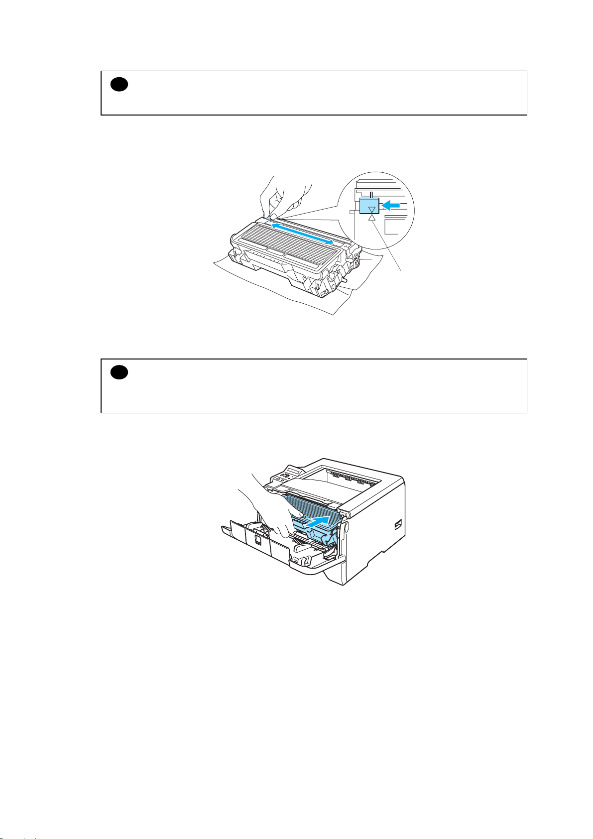
CHAPTER 3 PERIODIC MAINTENANCE
CAUTION:
!
Make sure that you put in the toner cartridge properly or it may separate from the drum unit.
(7) Clean the primary corona wire inside the drum unit by gently sliding the blue tab from right
to left and left to right several times.
Home position
Fig. 3-9
CAUTION:
!
Be sure to return the tab to the home position (▲). If you do not, printed pages may have a
vertical stripe.
(8) Put the drum unit and toner cartridge assembly back in the printer. Close the front cover.
Fig. 3-10
3-6
Confidential

1.2 Drum Unit
A new drum unit can print approximately 25,000 A4 or Letter size single-sided pages at 5%
coverage.
NOTE:
* There are many factors that determine the actual drum life, such as the temperature,
humidity, type of paper, type of toner used, number of pages per print job and so on. Under
ideal conditions, the average drum life is estimated at approximately 25,000 pages. The
actual number of pages that your drum will print may be significantly less than this estimate.
Because we have no control over the many factors that determine the actual drum life, we
cannot guarantee a minimum number of pages that will be printed by your drum.
* For the best performance, use only genuine Brother toner. The printer should be used only in
a clean, dust-free environment with adequate ventilation.
* Printing with a third-party drum unit may reduce not only the print quality but also the quality
and life of the printer itself. Warranty coverage does not apply to problems caused by the
use of a third-party drum unit.
<Change Drum Message>
(HL-5240/5250DN)
If the LED shows the message below, it means the drum unit is near the end of its life.
We recommend that you replace the drum unit with a new one before there is a noticeable
deterioration in the print quality.
HL-5240/5250DN/5270DN/5280DW SERVICE MANUAL
Fig. 3-11
(HL-5270DN/5280DW)
Appears at intervals.
DRUM NEAR END
If the LCD shows “DRUM NEAR END”, it means the drum unit is near the end of its life. We
recommend that you replace the drum unit with a new one before there is a noticeable
deterioration in the print quality.
3-7
Confidential

CHAPTER 3 PERIODIC MAINTENANCE
<Replacement Procedure>
CAUTION:
!
* While removing the drum unit, handle it carefully as it may contain toner.
* Every time you replace the drum unit, be sure to clean the inside of the printer.
When you replace the drum unit with a new one, you need to reset the drum counter by
completing the following steps:
(HL-5240/5250DN)
(1) Make sure that the printer is turned on and the Drum LED is blinking. Press the front
cover release button and then open the front cover.
(HL-5270DN/5280DW)
(1) Make sure that the LCD shows “DRUM NEAR END”. Press the front cover release button
and then open the front cover.
Fig. 3-12
(HL-5240/5250DN)
(2) Press and hold down Go for about 4 seconds until all the LEDs light up. Once all four
LEDs are lit, release Go.
Fig. 3-13
3-8
Confidential

HL-5240/5250DN/5270DN/5280DW SERVICE MANUAL
(HL-5270DN/5280DW)
(2) Hold down Go until the message “DRUM CLEAR” is displayed on the LCD, then release
Go.
Fig. 3-14
Improper Setup:
Do not reset the drum counter when you only replace the toner cartridge.
(3) Take out the drum unit and toner cartridge assembly.
Fig. 3-15
CAUTION:
!
* We recommend that you put the drum unit and toner cartridge assembly on a piece of
disposable paper or cloth in case you accidentally spill or scatter toner.
* To prevent damage to the printer from static electricity, DO NOT touch the electrodes shown
in the illustration.
3-9
Confidential

CHAPTER 3 PERIODIC MAINTENANCE
(4) Push down the blue lock lever and take the toner cartridge out of the drum unit.
CAUTION:
!
* Handle the toner cartridge carefully. If toner scatters on your hands or clothes, wipe or wash
it off with cold water at once.
* To avoid any degradation of the print quality, DO NOT touch the shaded parts shown in the
illustrations.
Fig. 3-16
NOTE:
* Be sure to seal up the toner cartridge tightly in a bag so that toner powder does not spill out
of the cartridge.
* Discard the used toner cartridge according to local regulations, keeping it separate from
domestic waste. If you have questions, call your local waste disposal office.
(5) Unpack the new drum unit.
CAUTION:
!
Wait to unpack a drum unit until immediately before you put it in the printer. Exposure to
direct sunlight or room light may damage the drum unit.
3-10
Confidential

HL-5240/5250DN/5270DN/5280DW SERVICE MANUAL
(6) Put the toner cartridge firmly into the new drum unit until you hear it lock into place. If you
put the cartridge in properly, the blue locklever will lift automatically.
Fig. 3-17
CAUTION:
!
Make sure that you put in the toner cartridge properly, or it may separate from the drum unit.
(7) Put the drum unit and toner cartridge assembly back in the printer.
Fig. 3-18
(HL-5240/5250DN)
(8) Close the front cover.
Make sure that the Drum LED is now off.
(HL-5270DN/5280DW)
(8) Close the front cover. Make sure that the “DRUM NEAR END” message on the LCD in
now off.
3-11
Confidential

CHAPTER 3 PERIODIC MAINTENANCE
2. PERIODICAL REPLACEMENT PARTS
2.1 Periodical Replacement Parts
Periodical replacement parts are the parts to be replaced periodically to maintain product
quality. These parts would affect the product quality greatly if they lost their function even if
they do not appear to be damaged or there is no change in their appearance.
The periodical replacement parts listed below should be replaced at the service center
referring to the service life.
Parts Name
Fuser Unit
Laser Unit
Paper feeding kit
for Tray 1 *3
Paper feeding kit
for Tray 2 *3
Paper feeding kit
for Tray 3 *3
Paper feeding kit
for MP tray *2
LCD Message
(HL-5270DN
/5280DW)
REPLACE FUSER
REPLACE LASER
REPLACE PF KIT1
REPLACE PF KIT2
REPLACE PF KIT3
REPLACE PF
KITMP
Qty
Approximate Life *1
(number of prints)
1 100,000 pages
1 100,000 pages
See subscription
2.2.1, Chapter 3
1 100,000 pages
1 100,000 pages
See subscription
2.2.2, Chapter 3
1 100,000 pages
1 100,000 pages
See subscription
2.2.3, Chapter 3
Replacement
Procedure
NOTE:
*1
At 5% print coverage (A4 or Letter size). The actual number of printed pages will vary
depending on the print jobs and paper you use.
*2
Paper feeding kit MP means the MP roller holder ASSY and the separation pad ASSY MP.
*3
Paper feeding kit for Tray 1, Tray 2 and Tray 3 means the roller holder ASSY, the separation
pad ASSY and the separation pad spring. Tray 1, Tray 2 and Tray 3 are the same kit.
NOTE:
* Always turn off the power switch of the printer and unplug the power cord from the power
outlet before replacing the periodical replacement parts.
* If the Fuser Unit is replaced after errors related to the Fuser Unit occur, it is necessary to
leave the printer power ON for ten minutes after part replacement. This will make the printer
to be released from errors.
* To reset the count of each periodical replacement parts, refer to “2.IF YOU REPLACE THE
PERIODICAL MAINTENANCE PARTS”, Chapter 6.
3-12
Confidential

HL-5240/5250DN/5270DN/5280DW SERVICE MANUAL
A
2.2 Procedures to Replace Periodical Replacement Parts
2.2.1 Fuser unit and laser unit
< Uninstalling Procedure >
(1) Disconnect the AC cord from the Printer.
<Back side>
Printer
(2) Press the front cover release button.
(3) Open the Front cover.
(4) Remove the Drum/toner ASSY.
2
Fig. 3-19
C cord
Printer
<Front side>
3
Drum/toner ASSY
4
Front cover
Fig. 3-20
3-13
Confidential

CHAPTER 3 PERIODIC MAINTENANCE
(5) Remove the DX feed ASSY or DX blank cover.
<Back side>
DX feed ASSY/ DX blank cover
Fig. 3-21
(6) Close the Front cover.
(7) Pull out the Paper tray.
(8) Remove the paper if it is remained in the Paper tray.
Front cover
<Front side>
6
Paper tray
Fig. 3-22
3-14
7
Confidential

(9) Open the Back cover.
(10) Remove the Arms of the Back cover from the Pins.
(11) Remove the Back cover.
9
11
HL-5240/5250DN/5270DN/5280DW SERVICE MANUAL
Pin
<Back side>
10
Pin
Fig. 3-23
Back cover
(12) Hold the Knobs on the Outer chute ASSY and pull down this to your side.
(13) Remove the Arms of the Outer chute ASSY from the Pins.
(14) Remove the Outer chute ASSY.
Pin
<Back side>
13
12
14
3
12
Pin
12
Fig. 3-24
3-15
Knob
Outer chute ASSY
Knob
Confidential
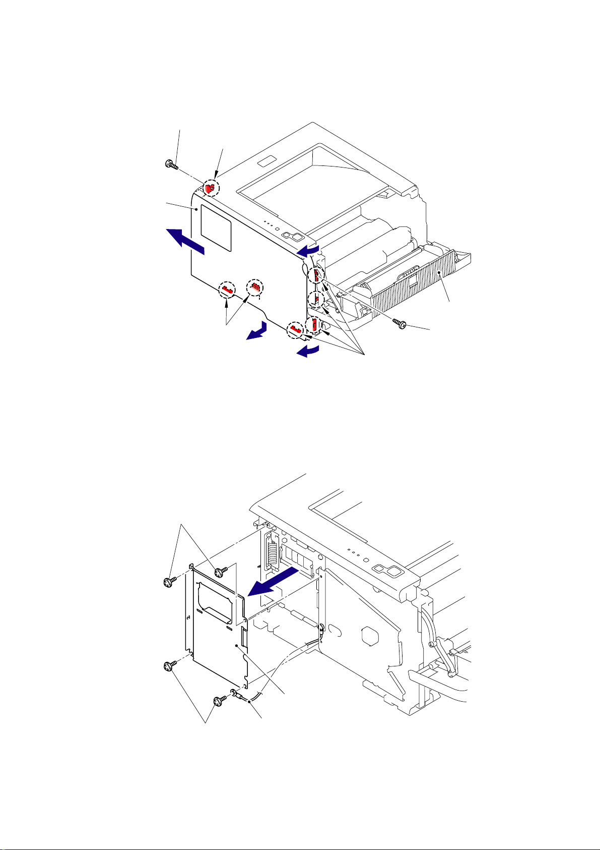
CHAPTER 3 PERIODIC MAINTENANCE
(15) Open the Front cover, remove the two bind B M4x12 Taptite screws, and then remove the
Side cover L by releasing the Hooks in the order of 15a to 15d.
Taptite, bind B M4x12
Side cover L
15d
Hook
<Front side>
15a
Front cover
Hooks
Taptite, bind B M4x12
15c
15b
Fig. 3-25
Hooks
(16) Remove the four cup S M3x6 SR Taptite screws to remove the Shield cover and the FG
harness.
Taptite, cup S M3x6 SR
Taptite, cup S M3x6 SR
Shield cover
FG harness
Fig. 3-26
3-16
Confidential

HL-5240/5250DN/5270DN/5280DW SERVICE MANUAL
(17) Remove the two bind B M4x12 Taptite screws, and then remove the Side cover R by
following the direction from 17a to 17d.
Taptite, bind B M4x12
Hook
Shield cover R
17d
Hook
17a
Taptite, bind B M4x12
Hooks
Hooks
17b
Hooks
Fig. 3-27
<Front side>
(18) Disconnect the Connector of the Panel PCB.
17c
Top cover printed ASSY
Connector
Main PCB
Panel PCB
Fig. 3-28
3-17
Confidential
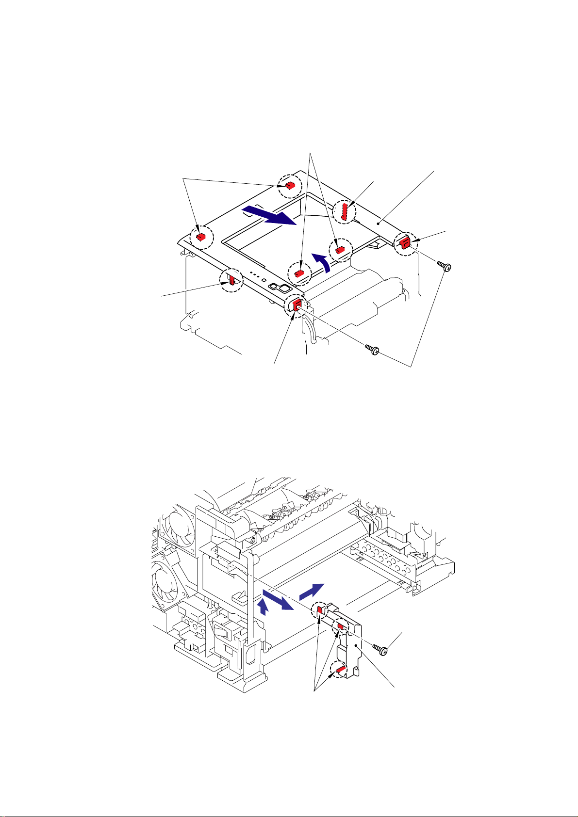
CHAPTER 3 PERIODIC MAINTENANCE
(19) Remove the two bind B M4x12 Taptite screws from Top cover printed ASSY.
(20) Release all Hooks of the Top cover printed ASSY and lift up the front side of the Top
cover printed ASSY.
(21) Remove the Top cover printed ASSY.
Hooks
Hooks
Hooks
21
Top cover printed ASSY
Hook
20
Hook
Hook
Fig. 3-29
Taptite, bind B M4x12
(22) Remove the bind B M4x16 Taptite screw. Release the Hooks in the order of 22a, 22b and
22c. Remove the FU harness cover 1.
22b
22a
Fig. 3-30
3-18
Hooks
22c
<Back side>
Taptite, bind B M4x16
FU harness cover 1
Confidential

HL-5240/5250DN/5270DN/5280DW SERVICE MANUAL
(23) Remove the Heater terminal L and Heater terminal S from the Fuser unit while holding the
Fuser unit.
Heater terminal L
Fuser unit
Heater terminal S
Fig. 3-31
(24) Pull the FU harness cover 2 to the direction of 24a while pressing the Hook and pull out
the FU harness cover 2 from the back of the printer.
24a
FU harness cover 2
Hook
24b
Fig. 3-32
3-19
Confidential

CHAPTER 3 PERIODIC MAINTENANCE
(25) Disconnect the connectors of the Thermistor ASSY M and Thermistor ASSY S from the
Relay rear PCB ASSY, and remove the harnesses of these thermistors.
Fuser unit
Thermistor ASSY M
Thermistor ASSY S
Relay rear PCB ASSY
Fig. 3-33
(26) Remove the cup B M4x16 Taptite screw to remove the Fuser unit.
Taptite, cup B M4x16
Fig. 3-34
3-20
Fuser unit
Confidential

HL-5240/5250DN/5270DN/5280DW SERVICE MANUAL
A
A
(27) Slide the Sub duct to the direction of 27b while pressing the three Hooks and remove the
Sub duct from the Air duct.
ir duct
Filter
27b
27a
Hooks
Sub duct
Fig. 3-35
(28) Remove the Filter from the Air duct.
NOTE:
The filter is dirt. Be careful when disassembling or assembling it.
ir duct
Filter
Fig. 3-36
3-21
Confidential

CHAPTER 3 PERIODIC MAINTENANCE
A
(29) Remove the Pin of the Air duct from the frame. Slide the Air duct to the direction of 29b
and remove the Air duct.
Pin
29a
Hook
ir duct
Fig. 3-37
Laser unit
Pin
Hook
29b
3
Pin
3-22
Confidential

HL-5240/5250DN/5270DN/5280DW SERVICE MANUAL
(30) Remove the six cup S M3x6 Taptite screws.
(31) Remove the two Flat cable from the Main PCB.
(32) Remove the Protective film.
(33) Pull out the flat cable from the Core.
(34) Remove the Laser unit.
NOTE:
- Be careful not to lose the Protective film attached on the flat cable.
- Do not touch the Laser scanner window directly.
Laser unit
Polygon motor
(Flat cable)
LD harness
(Flat cable)
Taptite, cup S M3x6
Taptite, cup S M3x6
LD harness
(Flat cable)
Main PCB
Polygon motor
(Flat cable)
Protective film
Core
Laser unit
Fig. 3-38
3-23
Confidential

CHAPTER 3 PERIODIC MAINTENANCE
A
< Installing Procedure >
(1) Secure the Laser unit with the six cup S M3x6 Taptite screws.
(2) Put the flat cable through the Core and Protective film.
(3) Install the flat cable. (Refer to “4. HARNESS ROUTING” in Chapter 5.)
Laser unit
Taptite, cup S M3x6
Core
Protective film
Taptite, cup S M3x6
(4) Install the Air duct into the Laser unit.
3
Fig. 3-39
Laser unit
Hook
4a
4b
Hook
ir duct
Pin
Fig. 3-40
3-24
Pin
Confidential

(5) Install the Filter into the Air duct.
A
A
Filter
HL-5240/5250DN/5270DN/5280DW SERVICE MANUAL
ir duct
Fig. 3-41
(6) Install the Sub duct into the Air duct.
ir duct
Filter
6a
6b
Hooks
Fig. 3-42
Sub duct
3-25
Confidential

CHAPTER 3 PERIODIC MAINTENANCE
• DO NOT subject the fuser unit to strong physical shocks or vibrations.
• DO NOT touch the rollers and the electrodes to prevent damage to the fuser unit In
the following figures.
CAUTION:
!
To prevent the deformation of the pressure roller, the fuser unit spare part is shipped with its
pressure roller at low nip pressure. Before installing the fuser unit, turn back the levers to the
normal position by following instructions below.
(1) Put the fuser unit on a flat, horizontal surface. Pull up each of the blue tab (a) on the right
side and left side.
WARNING
(a)
(b)
(2) Make sure that the black lever (b) is in the position in the illustration below.
(b)
(a)
3-26
Confidential

HL-5240/5250DN/5270DN/5280DW SERVICE MANUAL
(7) Secure the Fuser unit with the bind B M4x16 Taptite screw.
Fuser unit
Taptite, bind B M4x16
Fig. 3-43
(8) Connect the connectors of the Thermistor ASSY M and Thermistor ASSY S onto the relay
rear PCB ASSY.
Thermistor ASSY M
Fuser unit
Thermistor ASSY S
Relay rear PCB ASSY
Fig. 3-44
3-27
Confidential

CHAPTER 3 PERIODIC MAINTENANCE
(9) Install the FU harness cover 2.
FU harness cover 2
9b
Hook
9a
Fig. 3-45
(10) Install the Heater terminal L and Heater terminal S.
Heater terminal L
Fuser unit
Fig. 3-46
3-28
Heater terminal S
Confidential

HL-5240/5250DN/5270DN/5280DW SERVICE MANUAL
(11) Secure the FU harness cover 1 with the bind B M4x16 Taptite screw.
11a
11b
Taptite, bind B M4x16
Hooks
Fig. 3-47
FU harness cover 1
(12) Secure the Top cover printed ASSY with the two bind B M4x12 Taptite screws.
Hooks
Hooks
Hooks
12a
Top cover printed ASSY
Hook
12b
Hook
Hook
Fig. 3-48
3-29
Taptite, bind B M4x12
Confidential

CHAPTER 3 PERIODIC MAINTENANCE
(13) Connect the Connector of the Panel PCB.
Top cover printed ASSY
Connector
Main PCB
Fig. 3-49
Panel PCB
(14) Catch the Hooks in the order of the arrows and secure the Side cover R with the two bind
B M4x12 Taptite screws.
Taptite, bind B M4x12
14a
Hooks
Hook
14b
Fig. 3-50
Side cover R
Hooks
Hook
14c
14d
Taptite, bind B M4x12
Hooks
3-30
Confidential
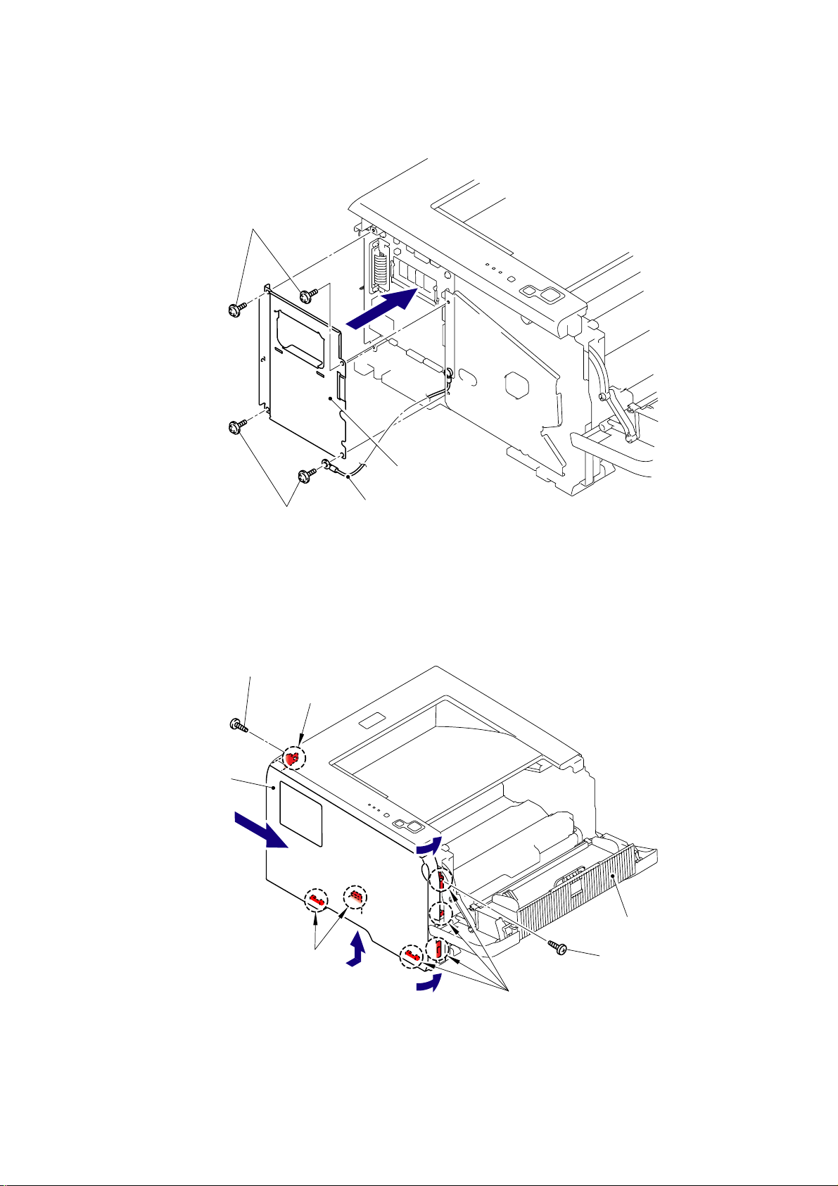
HL-5240/5250DN/5270DN/5280DW SERVICE MANUAL
(15) Secure the Shield cover and FG harness with the four cup S M3x6 SR Taptite screws.
Taptite, cup S M3x6 SR
Shield cover
Taptite, cup S M3x6 SR
FG harness
Fig. 3-51
(16) Catch the Hooks in the order of the arrows and secure the Side cover L with the two bind
B M4x12 Taptite screws.
Taptite, bind B M4x12
Hook
Side cover L
16a
16d
Hooks
16b
16c
Fig. 3-52
3-31
Hooks
Front cover
Taptite, bind B M4x12
Confidential

CHAPTER 3 PERIODIC MAINTENANCE
(17) Catch the Arm of the Outer chute ASSY onto the Pin of the machine body and install the
Outer chute ASSY.
Pin
17b
17c
17a
Outer chute ASSY
Pin
Fig. 3-53
(18) Catch the Arm of the Back cover onto the Pin of the machine body and install the Back
cover.
Pin
18b
18c
18a
Pin
Fig. 3-54
3-32
Back cover
Confidential

(19) Install the DX feed ASSY or DX blank cover.
HL-5240/5250DN/5270DN/5280DW SERVICE MANUAL
DX feed ASSY/ DX blank cover
Fig. 3-55
(20) Install the Drum/toner ASSY into the Printer.
(21) Close the Front cover.
Printer
21
Drum /toner ASSY
20
Front cover
Fig. 3-56
3-33
Confidential

CHAPTER 3 PERIODIC MAINTENANCE
A
(22) Put the Paper tray into the Printer.
Paper tray
Fig. 3-57
(23) Connect the AC cord into the Printer.
Printer
C cord
Fig. 3-58
3-34
Confidential

2.2.2 Paper feeding kit for tray 1, 2, 3
A
< Uninstalling Procedure >
(1) Disconnect the AC cord from the Printer.
HL-5240/5250DN/5270DN/5280DW SERVICE MANUAL
<Back side>
Printer
C cord
Fig. 3-59
(2) Press the front cover release button.
(3) Open the Front cover.
(4) Remove the Drum/toner ASSY.
Printer
2
<Front side>
3
Drum/toner ASSY
4
Front cover
Fig. 3-60
3-35
Confidential

CHAPTER 3 PERIODIC MAINTENANCE
(5) Remove the DX feed ASSY or DX blank cover.
<Back side>
DX feed ASSY/ DX blank cover
Fig. 3-61
(6) Close the Front cover.
(7) Pull out the Paper tray.
(8) Remove the paper from the Paper tray.
Front cover
<Front side>
6
Paper tray
Fig. 3-62
3-36
7
Confidential

HL-5240/5250DN/5270DN/5280DW SERVICE MANUAL
(9) Pull up the back side of the Separation pad ASSY.
(10) Push the Hooks provided on both sides of the Separation pad ASSY inwards.
(11) Pull up the Separation pad ASSY.
(12) Remove the Separation pad spring.
Separation pad spring
Hooks
Hook
10
Separation pad ASSY
10
Hook
11
9
<Front side>
Paper tray
Fig. 3-63
3-37
Confidential
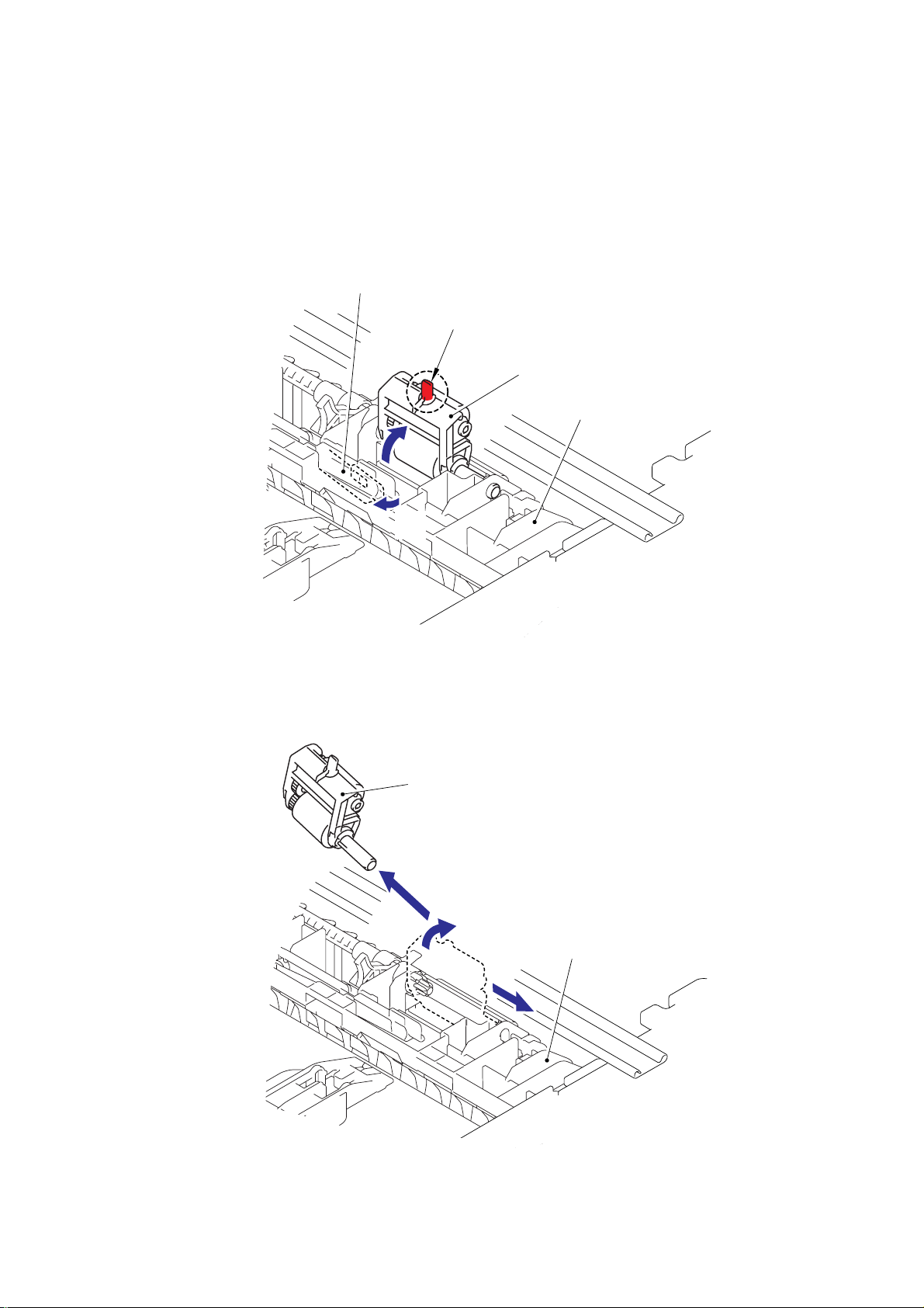
CHAPTER 3 PERIODIC MAINTENANCE
(13) Turn the Printer upside down.
NOTE:
• Pull out and put into the paper tray so that the Roller holder ASSY is lowered.
• If the Roller holder ASSY is remained up, it cannot be removed.
(14) Push the Lift arm to the direction of the arrow 14a and pull out the pin of the Roller holder
ASSY. Then, turn the Roller holder ASSY to the direction of the arrow 14b.
Lift arm
Pin
Roller holder ASSY
Paper feed frame
14b
14a
Fig. 3-64
(15) Slide the Roller holder ASSY to the direction of the arrow 15a. Then, lift up the gear side
of the Roller holder ASSY to the direction of the arrow 15b and pull it out to the direction
of the arrow 15c to remove.
Roller holder ASSY
15c
15b
Paper feed frame
15a
Fig. 3-65
3-38
Confidential

< Installing Procedure >
(1) Install the Roller holder ASSY.
NOTE:
When assembling the roller holder ASSY, align the section “A” on the shaft of the roller
holder ASSY with the hole on the paper feed frame.
HL-5240/5250DN/5270DN/5280DW SERVICE MANUAL
Roller holder ASSY
1a
1b
“A”
Paper feed frame
1c
Fig. 3-66
(2) Assemble the Lift arm onto the Pin of the Roller holder ASSY.
(3) Place the Printer on its base.
Lift arm
Pin
2a
2b
Fig. 3-67
3-39
Roller holder ASSY
Paper feed frame
Confidential
 Loading...