Brother HL2700CN Service Manual
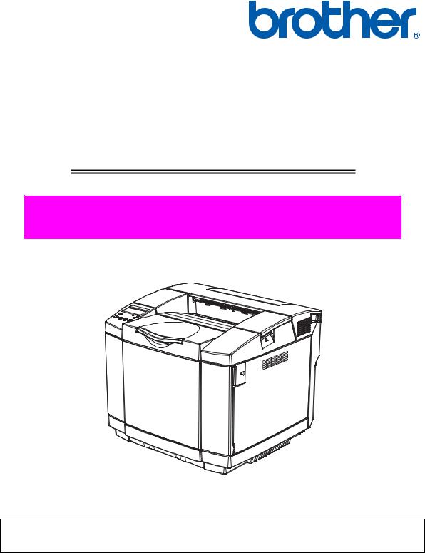
Brother Color Laser Printer
SERVICE MANUAL
MODEL: HL-2700CN
Read this manual thoroughly before maintenance work.
Keep this manual in a convenient place for quick and easy reference at all times.
October 2005
© Copyright Brother 2003 All rights reserved.
No part of this publication may be reproduced in any form or by any means without permission in writing from the publisher.
Specifications are subject to change without notice.
Trademarks:
The brother logo is a registered trademark of Brother Industries, Ltd.
Apple, the Apple Logo, and Macintosh are trademarks, registered in the United States and other countries, and True Type is a trademark of Apple computer, Inc.
Epson is a registered trademark and FX-80 and FX-850 are trademarks of Seiko Epson Corporation.
Hewlett Packard is a registered trademark and HP Laser Jet is a trademark of Hewlett Packard Company.
IBM, IBM PC and Proprinter are registered trademarks of International Business Machines Corporation.
Microsoft and MS-DOS are registered trademarks of Microsoft Corporation.
Windows is a registered trademark of Microsoft Corporation in the U.S. and other countries.
PREFACE
This service manual contains basic information required for after-sales service of the color laser printer (here-in-after referred to as "this machine" or "the printer"). This information is vital to the service technician to maintain the high printing quality and performance of the printer.
This service manual covers the HL-2700CN color laser printer. This manual consists of the following chapters:
CHAPTER I : OUTLINE OF PRODUCT
Features, parts names, internal structure, and description of the control panel.
CHAPTER II : SPECIFICATIONS
Specifications, etc.
CHAPTER III : INSTALLATION
Installation conditions and installation procedures.
CHAPTER IV : STRUCTURE OF SYSTEM COMPONENTS
Basic operation of the mechanical system, the electrical system and the electrical circuits and their timing information.
CHAPTER V : CONTROL PANEL OPERATION
Operation and setting procedures on the control panel.
CHAPTER VI : PERIODIC MAINTENANCE
Description of periodic maintenance parts, and procedures for periodic replacement and cleaning.
CHAPTER VII : DISASSEMBLY
Procedures for replacement of the mechanical system parts.
CHAPTER VIII : TROUBLESHOOTING
Description of error messages on the control panel, troubleshooting image failure, etc.
APPENDICES :SERIAL NO. DESCRIPTIONS, ETC.
Information in this manual is subject to change due to improvement or re-design of the product. All relevant information in such cases will be supplied in service information bulletins (Technical Information).
A thorough understanding of this printer, based on information in this service manual and service information bulletins, is required for maintaining its print quality performance and for improving the practical ability to find the cause of problems.
CONTENTS
CHAPTER I PRODUCT OUTLINE ..................................................... |
I-1 |
|
1. FEATURES...................................................................................................... |
I-1 |
|
2. PARTS NAMES & FUNCTIONS ...................................................................... |
I-4 |
|
3. INTERNAL STRUCTURE ................................................................................ |
I-6 |
|
4. DESCRIPTION OF CONTROL PANEL ........................................................... |
I-7 |
|
4.1 |
Video Controller Mode ......................................................................................................... |
I-7 |
4.2 |
Engine Controller Mode ....................................................................................................... |
I-7 |
CHAPTER II SPECIFICATIONS....................................................... |
II-1 |
1. RATING .......................................................................................................... |
II-1 |
2. GENERAL SPECIFICATIONS ........................................................................ |
II-2 |
2.1. Printing ............................................................................................................................... |
II-2 |
2.2. Functions............................................................................................................................ |
II-3 |
2.3. Electrical and Mechanical .................................................................................................. |
II-3 |
2.4. Network .............................................................................................................................. |
II-4 |
2.5. Paper Specification ............................................................................................................ |
II-5 |
2.6. Toner Cartridge Weight information................................................................................... |
II-9 |
3. ENVIRONMENTAL CONDITION ................................................................... |
II-10 |
3.1 Ambient Temperature / Humidity / Altitude ....................................................................... |
II-10 |
CHAPTER III INSTALLATION......................................................... |
III-1 |
|
1. CONDITIONS REQUIRED FOR INSTALLATION.......................................... |
III-1 |
|
1.1. Environmental Conditions ................................................................................................. |
III-1 |
|
1.2. Basic Layout of Printer Set-up Location............................................................................ |
III-1 |
|
2. UNPACKING.................................................................................................. |
III-2 |
|
2.1 |
Unpacking of Printer........................................................................................................... |
III-2 |
2.2 |
Unpack the Starter Kit ........................................................................................................ |
III-4 |
3. INSTALLATION WORK ................................................................................. |
III-5 |
|
3.1 |
Install the Toner Cartridge PU............................................................................................ |
III-5 |
3.2 |
Install the OPC Belt Cartridge ............................................................................................ |
III-6 |
3.3 |
Install the Toner Cartridge to the Printer............................................................................ |
III-8 |
3.4 |
Test Print ............................................................................................................................ |
III-9 |
CHAPTER IV STRUCTURE OF SYSTEM COMPONENTS ............ |
IV-1 |
|
1. BASIC STRUCTURE .................................................................................... |
IV-1 |
|
1.1 |
Print System and Transfer System .................................................................................... |
IV-6 |
1.2 |
Laser Assy PU.................................................................................................................. |
IV-20 |
1.3 |
Paper Transportation System .......................................................................................... |
IV-22 |
1.4 |
Fusing Unit ....................................................................................................................... |
IV-24 |
2. STRUCTURE OF THE CONTROL SYSTEM.............................................. |
IV-26 |
|
2.1 |
Basic Structure................................................................................................................. |
IV-26 |
2.2 |
Control System................................................................................................................. |
IV-34 |
2.3 |
Main PCB (Video Controller PCB) ................................................................................... |
IV-42 |
2.4 |
Power Supply Unit............................................................................................................ |
IV-56 |
2.5 |
High Voltage Power Supply Unit...................................................................................... |
IV-61 |
2.6 |
Wiring Diagram................................................................................................................. |
IV-64 |
CHAPTER V CONTROL PANEL OPERATION .............................. |
V-1 |
|
1. PANEL LAYOUT............................................................................................ |
V-1 |
|
2. VIDEO CONTROLLER MODE....................................................................... |
V-2 |
|
2.1 |
Configuration of Operational Mode ..................................................................................... |
V-2 |
2.2 |
Line Test Mode.................................................................................................................... |
V-3 |
2.3 DRAM Test Mode................................................................................................................ |
V-8 |
|
2.5 NVRAM Reset Mode........................................................................................................... |
V-9 |
|
3. ENGINE CONTROLLER MODE .................................................................. |
V-10 |
|
3.1 |
Configuration of Operational Mode ................................................................................... |
V-10 |
3.2 |
Operation of Normal Mode................................................................................................ |
V-12 |
3.3 |
Service Mode .................................................................................................................... |
V-19 |
3.4 |
Adjustment Work Procedures ........................................................................................... |
V-42 |
CHAPTER VI PERIODIC MAINTENANCE...................................... |
VI-1 |
|
1. GENERAL..................................................................................................... |
VI-1 |
|
1.1 |
Precautions in Handing ...................................................................................................... |
VI-1 |
1.2 |
Cleaning for Periodic Maintenance .................................................................................... |
VI-4 |
1.3 |
Periodic Maintenance Parts and Maintenance Cycle ...................................................... |
VI-10 |
2. PERIODIC MAINTENANCE PROCEDURES.............................................. |
VI-12 |
|
2.1 |
Replacement of OPC Belt Cartridge ................................................................................ |
VI-12 |
2.2 |
Replacement of Fusing Unit............................................................................................. |
VI-14 |
2.3 |
Replacement of Transfer Roller Assy PU ........................................................................ |
VI-16 |
2.4 |
Replacement of Cleaning Roller Cover PU...................................................................... |
VI-18 |
2.5 |
Replacement of Paper Feed Roller and Separator Pad .................................................. |
VI-20 |
2.6 |
Replacement of Transfer Unit PU .................................................................................... |
VI-24 |
CHAPTER VII DISASSEMBLY...................................................... |
VII-1 |
||
1. REPLACEMENT PROCEDURE OF MAINTENANCE PARTS..................... |
VII-1 |
||
2. PARTS NAME............................................................................................... |
VII-4 |
||
2.1 Cover................................................................................................................................. |
VII-4 |
||
2.2 Arrangement Boards ......................................................................................................... |
VII-5 |
||
2.3 Motor Units ........................................................................................................................ |
VII-5 |
||
2.4 Clutches and Solenoids .................................................................................................... |
VII-6 |
||
2.5 Sensors ............................................................................................................................. |
VII-6 |
||
3. DISASSEMBLY FLOW ................................................................................ |
VII-7 |
||
4. DISASSEMBLY PROCEDURE .................................................................. |
VII-11 |
||
4.1 |
OPC Charge Roller PU..................................................................................................... |
VII-11 |
|
4.2 |
Paper Tray ........................................................................................................................ |
VII-11 |
|
4.3 |
Fuser Unit ......................................................................................................................... |
VII-12 |
|
4.4 |
Cleaning Roller Cover PU / Cleaning Roller PU............................................................. |
VII-116 |
|
4.5 |
Top Cover Assy PU / Top Cover PU ................................................................................ |
VII-17 |
|
4.6 |
Right Side Cover PU......................................................................................................... |
VII-18 |
|
4.7 |
Main PCB.......................................................................................................................... |
VII-18 |
|
4.8 |
Left Side Cover PU / Duplex Connector Cover ................................................................ |
VII-19 |
|
4.9 |
Interlock Switch PU (Front)............................................................................................... |
VII-19 |
|
4.10 |
I/O Board Cover PU / I/O Board PU ............................................................................... |
VII-20 |
|
4.11 |
Power Supply Fan PU / Interlock Switch PU (Top, Paper Exit) / |
|
|
|
|
Power Supply Fan Duct PU............................................................................................ |
VII-21 |
4.12 |
Waste Toner Auger PU................................................................................................... |
VII-22 |
|
4.13 |
Waste Toner Agitator PU................................................................................................ |
VII-22 |
|
4.14 |
Erase Lamp PU .............................................................................................................. |
VII-23 |
|
4.15 |
Marker Sensor ................................................................................................................ |
VII-24 |
|
4.16 |
Toner Density Sensor PU............................................................................................... |
VII-24 |
|
4.17 |
Cleaning Roller Clutch PU.............................................................................................. |
VII-25 |
|
4.18 |
Main Motor PU................................................................................................................ |
VII-25 |
|
4.19 |
Fuser Clutch PU ............................................................................................................. |
VII-26 |
|
4.20 |
TR Cam Clutch ............................................................................................................... |
VII-27 |
|
4.21 |
Registration Clutch PU ................................................................................................... |
VII-27 |
|
4.22 |
Paper Feed Clutch PU.................................................................................................... |
VII-28 |
|
4.23 |
Developer Motor PU ....................................................................................................... |
VII-28 |
|
4.24 |
Waste Toner Holder Assy PU......................................................................................... |
VII-29 |
|
4.25 |
Developer Clutch PU (DCLY/DCLM/DCLC/DCLK) ........................................................ |
VII-29 |
|
4.26 |
Developer Gear PU / Developer Drive Assy PU ............................................................ |
VII-30 |
|
4.27 |
OPC Drive Gear Assy PU............................................................................................... |
VII-30 |
|
4.28 |
Main Drive Gear Assy PU............................................................................................... |
VII-31 |
|
4.29 |
Waste Toner Feeder PU................................................................................................. |
VII-32 |
|
4.30 |
Toner Sensor PU (TPD) ................................................................................................. |
VII-33 |
|
4.31 |
Right Toner Guide PU .................................................................................................... |
VII-34 |
|
4.32 |
Laser Assy PU / Laser Unit Fan Assy PU ...................................................................... |
VII-34 |
|
4.33 |
Inner Front Cover PU / Front Cover PU ......................................................................... |
VII-36 |
|
4.34 |
Right Tray Guide PU....................................................................................................... |
VII-36 |
4.35 |
Engine Control Board PU ............................................................................................... |
VII-37 |
4.36 |
HV Power Supply PU...................................................................................................... |
VII-38 |
4.37 |
LV Power Supply PU / Power Supply Bracket PU Assy................................................. |
VII-39 |
4.38 |
Fuser Connector PU ....................................................................................................... |
VII-40 |
4.39 |
Toner Retract Solenoid PU (DESLY/DESLM/DESLC/DESLK) / |
|
|
Toner Retract Cam PU.................................................................................................... |
VII-41 |
4.40 |
Toner Sensor PU (TTR).................................................................................................. |
VII-42 |
4.41 |
Toner Present Sensor PU............................................................................................... |
VII-43 |
4.42 |
Belt Sensor ..................................................................................................................... |
VII-43 |
4.43 |
Left Tray Guide PU / Paper Size Sensor PU / Room Temp Thermistor PU .................. |
VII-44 |
4.44 |
Left Toner Guide PU....................................................................................................... |
VII-45 |
4.45 |
Upper Duplex Cover / Lower Duplex Cover ................................................................... |
VII-45 |
4.46 |
Paper Exit Unit................................................................................................................ |
VII-46 |
4.47 |
Transfer Roller Assy PU ................................................................................................. |
VII-47 |
4.48 |
Transfer Base Assy PU .................................................................................................. |
VII-47 |
4.49 |
Registration Roller Assy PU ........................................................................................... |
VII-48 |
4.50 |
Registration Actuator PU ................................................................................................ |
VII-48 |
4.51 |
Transfer Roller Guide PU ............................................................................................... |
VII-49 |
4.52 |
Exit Guide Assy PU / Exit Drive Assy PU / Exit Idle Roller Assy PU.............................. |
VII-49 |
4.53 |
Paper Sensor (PFUL) ..................................................................................................... |
VII-51 |
4.54 |
Exit Roller Assy PU / Paper Exit Actuator PU ................................................................ |
VII-51 |
4.55 |
Fuser Exit Actuator PU................................................................................................... |
VII-52 |
4.56 |
Paper Sensor (PT2) ................................................................................................... |
VII-52 |
4.57 |
Discharging Brush PU .................................................................................................... |
VII-53 |
4.58 |
Exit Fan PU / Exit Fan Duct PU ...................................................................................... |
VII-54 |
4.59 |
Rear Cover Latch Assy PU............................................................................................. |
VII-55 |
4.60 |
Paper Guide (A) PU........................................................................................................ |
VII-56 |
4.61 |
Paper Guide (B) PU........................................................................................................ |
VII-56 |
4.62 |
Paper Guide (C) PU / Paper Sensor (PT1, PEU) / OHP Sensor PU / |
|
|
Tray Empty Actuator PU................................................................................................. |
VII-57 |
4.63 |
Paper Guide (D) PU........................................................................................................ |
VII-58 |
4.64 |
Paper Feed Roller / Separator Pad ................................................................................ |
VII-58 |
5. ADJUSTMENTS AND UPDATING OF SETTINGS, REQUIRED AFTER |
|
|
PARTS REPLACEMENT ............................................................................. |
VII-59 |
|
CHAPTER VIII TROUBLESHOOTING ......................................... |
VIII-1 |
|
1. OUTLINE OF TROUBLESHOOTING....................................................... |
VIII-1 |
|
2. OPERATOR CALL ................................................................................... |
VIII-2 |
|
2.1 |
Operator call ..................................................................................................................... |
VIII-2 |
2.2 |
In case that the operator call is not cleared ..................................................................... |
VIII-5 |
3. PAPER TRANSPORT ERROR .............................................................. |
VIII-18 |
|
3.1 |
Feed Jam........................................................................................................................ |
VIII-18 |
3.2 |
Inner Jam........................................................................................................................ |
VIII-19 |
4. PRINTER ERROR........................................................................................ |
VIII-20 |
|
4.1 Error Code ...................................................................................................................... |
VIII-21 |
5. IMAGE FAILURE ...................................................................................... |
VIII-59 |
APPENDIX A .................................................................................... |
A-1 |
|
1. SERIAL NO. DESCRIPTIONS ........................................................................ |
A-1 |
|
2. DIAMETER / CIRCUMFERENCE OF ROLLERS............................................ |
A-5 |
|
3. SHELF LIFE OF EACH CONSUMABLE ......................................................... |
A-6 |
|
4. CONSUMABLES REPLACEMENT................................................................. |
A-7 |
|
5. RE-PACKING INSTRUCTIONS...................................................................... |
A-9 |
|
6. HIDDEN FUNCTION MENU ......................................................................... |
A-11 |
|
6.1 |
Professional Menu .............................................................................................................. |
A-11 |
6.2 |
Reset Parts Life .................................................................................................................. |
A-23 |
6.3 |
Service Menu...................................................................................................................... |
A-24 |
7. TO INSTALL THE PRINTER CORRECTLY.................................................. |
A-27 |
|
8. HOW TO REWRITE HL2700 FLASH ROM ................................................. |
A-31 |
|
9. NVRAM BACKUP ........................................................................................ |
A-33 |
|
REGULATIONS
LASER SAFETY (FOR 110-120 V MODEL ONLY)
This printer is certified as a Class I laser product under the U.S. Department of Health and Human Services (DHHS) Radiation Performance Standard according to the Radiation Control for Health and Safety Act of 1968. This means that the printer does not produce hazardous laser radiation.
Since radiation emitted inside the printer is completely confined within protective housings and external covers, the laser beam cannot escape from the machine during any phase of user operation.
FDA REGULATIONS (FOR 110-120 V MODEL ONLY)
U.S. Food and Drug Administration (FDA) has implemented regulations for laser products manufactured on and after August 2, 1976. Compliance is mandatory for products marketed in the United States. One of the following labels on the back of the printer indicates compliance with the FDA regulations and must be attached to laser products marketed in the United States.
Caution
Use of controls, adjustments or performance of procedures other than those specified in this manual may result in hazardous radiation exposure.
i

IEC 60825 SPECIFICATION (FOR 220-240 V MODEL ONLY)
This printer is a Class 1 laser product as defined in IEC 60825 specifications. The label shown below is attached in countries where required.
CLASS 1LASER PRODUCT
APPAREIL Å LASER DE CLASSE 1
LASER KLASSE 1 PRODUKT
This printer has a Class 3B Laser Diode which emits invisible laser radiation in the Scanner Unit. The Scanner Unit should not be opened under any circumstances.
Caution
Use of controls, adjustments or performance of procedures other than those specified in this manual may result in hazardous radiation exposure.
The following caution label is attached near the scanner unit.
5mW
7 8 0 n m - 8 0 0 n m
DANGER-
VORSICHT- UNSICHTBARE LASERSTRAHLUNG, WENN ABDECKUNG GEÖFFNET UND SICHERHEITSVERRIEGELUNG ÜBERBRÜCKT. NICHT DEM STRAHL AUSSETZEN.
DANGERPELIGRO-
RAYON LASER INVISIBLE LORS DE L’OUVER TURE. EVITER L’EXPOSITION DIRECTE.
RADIACION LASER INVISIBLE AL ABRIR. EVITAR LA EXPOSICION DIRECTA AL HAZ.
MAS
For Finland and Sweden LUOKAN 1 LASERLAITE KLASS 1 LASER APPARAT
Varoitus! Laitteen käyttäminen muulla kuin tässä käyttöohjeessa mainitulla tavalla saattaa altistaa käyttäjän turvallisuusluokan 1 ylittävälle näkymättömälle lasersäteilylle.
Varning – Om apparaten används på annat sätt än i denna Bruksanvisning specificerats, kan användaren utsättas för osynlig laserstrålning, som överskrider gränsen för laserklass 1.
ii
SAFETY INSTRUCTIONS
SAFETY PRINCIPLE
1)Before starting any operations, read this manual thoroughly. Especially read the safety instructions in this section carefully and ensure that you understand the contents.
2)Perform all the operations by following the procedures described in this manual. Follow all the cautions and warnings set out in the procedures and on safety labels affixed to the machine. Failure to do so may result in human injury or equipment damage.
3)Perform only the procedures explained in this manual. Refrain from opening or touching any portions that are not related to your required operation(s).
4)Repair and replacement of parts should be performed by trained and qualified persons only. Operators should not attempt to do such repair or replacement work.
5)It must be appreciated that the above-mentioned cautions and warnings do not cover everything because it is impossible to evaluate all the circumstances of repair situations.
SPECIAL SAFETY INFORMATION
Introductory Information
Cautions and warnings are made clear by following the ‘Safety Alert Symbols’ or ‘Signal Words’ such as DANGER, WARNING and CAUTION.
<SAFETY ALERT SYMBOL>
This is the safety alert. When you find this symbol placed on the equipment or marked in this manual, be aware of the potential of human injuries. Follow the recommended precautions and safety operation practices.
<Understanding Signal Words>
DANGER is used to indicate the presence of a hazard which will cause severe human injuries or a fatal accident if the warning is ignored.
WARNING is used to indicate the presence of a hazard or unsafe practices which may cause severe human injuries or a fatal accident if the warning is ignored.
CAUTION is used to indicate the presence of a hazard or unsafe practices which may cause minor human injuries if the warning is ignored. CAUTION also calls your attention to safety messages in this manual.
<Follow Safely Instructions>
Carefully read all the safety messages set out in this manual and also in the safety warning signs placed on the equipment. In this manual, the safety instructions (safety alert symbols and signal words) are enclosed in a rectangular enclosure to bring them to your attention. Keep the safety signs on the equipment in good condition and ensure none are missing or damaged. Replace the safety signs if unreadable or damaged. Learn how to operate the equipment and how to use the controls properly. Do not let anyone operate this equipment without following the instructions. Keep the equipment in proper working condition. Unauthorized modification to the equipment may impair the function & safety and affect the life of the equipment.
Listed below are the various kinds of “WARNING” messages contained in this manual.
iii

 WARNING
HAZARDOUS VOLTAGE
May cause serious injuries or fatal accidents. Voltage is now applied from the power supply of printer. There is a danger of electrical shock if you touch the active area inside the printer.
Be sure to turn the power supply switch OFF and pull the plug out from the power outlet before starting maintenance work on the printer.
 WARNING
HOT SURFACE
The Fusing Unit reaches a temperature of approx.170°C and adjacent parts are also very hot.
When you need to change the cleaning pad or remove jammed paper, wait about 20 minutes after opening the paper exit unit to allow the unit to cool down.
 CAUTION
ROTATING PARTS
Be aware of the potential danger of various rollers and take care not to get your fingers or hand caught into the machine, this can cause serious injuries. Note that the exit roller that ejects the printed paper is rotating while printing.
Be careful not to get your hair, fingers, hands, sleeve or necktie caught in the machine while operating the machine.
iv

 CAUTION
HAZARDOUS POWDER
Toner is a fine powder which can cause a powder explosion if disposed of into a fire. Under no circumstances dispose of toner into a fire.
 CAUTION
HAZARDOUS POWDER
Toner is a fine powder which may cause irritation to the eyes and respiratory organs if inhaled.
Handle the toner cartridge, waste toner pack and developing unit carefully so as not to spill the toner.
 CAUTION
POWER CORDS & PLUGS
This printer is equipped with a 3-wire power cord fitted with a 3-pronged plug (bi-polar plug with grounding) for the user’s safety.
Use these power cords in conjunction with a properly grounded electrical outlet to avoid an electrical shock.
 CAUTION
SAFETY INTERLOCK
The front cover, paper exit unit and transfer unit of this printer have electrical safety interlocks to turn the power off whenever they are opened. Do not attempt to circumvent these safety interlocks.
v
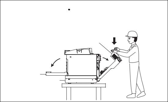
 CAUTION
Do not lean against or apply any excessive force to the paper cassette, open cover of Duplex unit. Otherwise it may cause the product to decline or fall down and result in the injuries.
Rear Cover Unit
Front Door |
Lower Feeder Unit |
vi
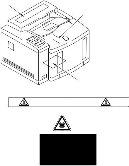
<Label Location>
1
1.Hot Caution Label
2.Laser Caution Label
3
2
170 C/338
C/338 F
F
5mW
7 8 0 n m - 8 0 0 n m
DANGER-
VORSICHT- UNSICHTBARE LASERSTRAHLUNG, WENN ABDECKUNG GEÖFFNET UND SICHERHEITSVERRIEGELUNG ÜBERBRÜCKT. NICHT DEM STRAHL AUSSETZEN.
DANGER- RAYON LASER INVISIBLE LORS DE L’OUVER TURE. EVITER L’EXPOSITION DIRECTE.
PELIGRO- RADIACION LASER INVISIBLE AL ABRIR. EVITAR LA EXPOSICION DIRECTA AL HAZ.
MAS
vii
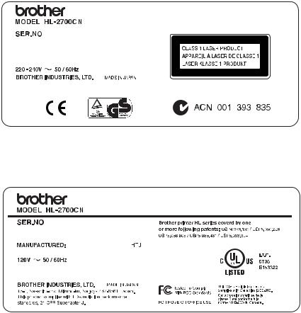
3. Rating Label |
(For Europe) |
|
|
6.0A
(For US)
11.0A
viii
SHIPMENT OF THE PRINTER
If for any reason you must ship the printer, carefully package the printer to avoid any damage during transit. It is recommended that you save and use the original packaging. The printer should also be adequately insured with the carrier.
ix
CHAPTER I
PRODUCT OUTLINE
CHAPTER I PRODUCT OUTLINE
1.FEATURES
This printer has the following features:
2400 dpi Class Resolution
The printer prints at a default resolution of 600 dots per inch (dpi). You can get a higher print quality, equivalent to 2400 dpi class resolution by using Brother technologies: High Resolution Control (HRC) and Color Advanced Photoscale Technology (CAPT).
High Speed Color Laser Printing
You can print crisp images in brilliant 24-bit color.
This printer can print at speeds up to 31 pages per minute in monochrome mode and 8 pages per minute in full color mode. The HL-2700CN controller uses a high speed 64-bit RISC microprocessor and special hardware chips, to ensure fast print job processing.
High Resolution Control (HRC)
The high resolution control (HRC) technology gives you clear and crisp printouts and improves even the 600 dpi resolution. HRC is most effective when printing text data.
Color Advanced Photoscale Technology (CAPT)
This printer can print graphics in 256 shades for each color in PCL6 emulation and BR-Script3, producing nearly photographic quality. CAPT is most effective when printing photographic images.
Maintenance-Free Toner Cartridge
This printer uses four easy-to-replace toner cartridges. The toner cartridges can print up to 6,600 (Cyan, Magenta and Yellow) and 10,000 (Black) single-sided pages at approximately 5% coverage.
Universal Paper Tray
This printer loads paper automatically from the paper tray. Since the paper tray is a universal type, a number of different paper sizes (one paper size at a time) can be used. Even envelopes can be loaded from the paper tray.
I-1
Three Interfaces
This printer has a high speed, bi-directional parallel interface, USB and Ethernet 10/100BaseTX.
If your application software supports the bi-directional parallel interface, you can monitor the printer status. It is fully compatible with the industry-standard bi-directional parallel interface.
HL-2700CN can use the TCP/IP, IPS/SPX, Apple Talk, DLC/LLC, Banyan VINES, DEC LAT and NetBEUI environments. Also, many useful utilities, such as BRAdminProfessional for the administrator and Brother network printing software, are included in the CD-ROM supplied with the HL-2700CN printer.
Automatic Interface Selection
The printer can automatically select the bi-directional parallel, USB, NETWORK depending on the interface port through which it receives data. With this feature, the printer can be connected to more than one computer.
Five Emulation Modes
The printer can emulate Hewlett-Packard Color PCL® 5C (PCL6® in monochrome mode) and PostScript® 3 language emulation (Brother BR-Script 3) printers, the industry-standard HP-GL™ plotter as well as EPSON® FX-850™, and IBM® Proprinter XL® printers (in monochrome mode). You can print with all application programs that support one of these printers.
Automatic Emulation Selection
The printer can automatically select the printer emulation mode, depending on the print commands it receives from the computer software. With this feature, many users can share the printer on a network.
Data Compression Technology
The printer can internally compress the received graphics and font data in its memory so it can print larger graphics and more fonts without additional memory.
I-2
Various Fonts
The printer has 66 scalable and 12 bitmapped fonts. The fonts that can be used will vary according to the selected emulation mode.
In PCL mode, you can also print the 13 kinds of bar codes listed below. In BR-Script mode, the printer has 35 scalable fonts.
< Bar Code Printing >
This printer can print the following 13 types of bar codes:
• |
Code 39 |
• |
UPC-E |
• |
Interleaved 2 of 5 |
• |
Codabar |
• |
EAN-8 |
• |
FIM (US-PostNet) |
• |
EAN-13 |
• |
Post Net (US-PostNet) |
• |
EAN-128 |
• |
ISBN (EAN) |
• |
Code 128 |
• |
ISBN (UPC-E) |
• |
UPC-A |
|
|
Panel Lock Setting
If the panel button settings have been changed, the printer may not work as expected. If you are an administrator of this printer, you can lock the settings to prevent changes from being made.
Power Save Mode
The printer has a power saving mode. Since laser printers consume power to keep the fixing assembly at a high temperature, this feature can save electricity when the printer is ON but not being used. The factory setting of the Power Save mode is ON so that it complies with the EPA Energy Star new specification.
Toner Save Mode
The printer has an economical toner save mode. By using this feature you can substantially reduce operating costs and extend the life expectancy of the toner cartridges.
Reprint Setting
The printer saves data that you reprinted. You can reprint a document without sending the data again from your PC. If you do not install a CompactFlash™ card, you can reprint from RAM.
Network
Ethernet 10/100BASE-TX enables you to use the printer in the following environments:
(TCP/IP, IPX/PSX, Apple Talk, DLC/LLC, NetBEUI)
Also, many useful utilities, such as BRAdminProfessional Utility, Driver Development Wizard and Web BRAdmin software for the Network administrator, are included.
I-3
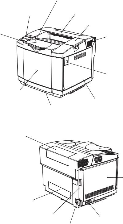
2.PARTS NAMES & FUNCTIONS
<Front View>
Top Cover Assy PU
Rear Cover Assy PU
Operator Panel
Top Cover PU
Paper Stopper
Release Lever H
Release Lever
Front Cover PU
Right Side Cover PU
Paper Tray PU
Fig.1-1
<Rear View>
Upper Duplex Cover PU
Rear Cover Assy PU
Left Side Cover PU
Lower Duplex Cover PU
Interface Control Box
Power Switch
AC Input Inlet
Fig.1-2
I-4

No. |
Part Name |
Outline of Functions |
|
|
|
1 |
Top Cover PU |
To act as both of the upper enclosure and paper |
|
|
tray for printed papers, and to be opened up at |
|
|
the maintenance. |
|
|
|
2 |
Operator Panel |
To display a status of printer operation and |
|
|
motion. |
|
|
|
3 |
Front Cover PU |
To act as a front enclosure, and to be opened |
|
|
when replacing a toner cartridge or waste toner |
|
|
pack. |
|
|
|
4 |
Rear Cover Assy PU |
To exit the printed paper for transportation. (To |
|
|
be opened when clearing the internal jam or |
|
|
doing the maintenance.) |
|
|
|
5 |
Power Switch |
To power on or off the printer. |
|
|
(Located at the lower left of the left side cover |
|
|
PU) |
|
|
|
6 |
AC Input Inlet |
To connect a power supply cable. |
|
|
|
7 |
Interface Connector Box |
Space for a controller board to be installed. |
|
|
|
8 |
Upper Duplex Cover PU |
Cover to be provided at the duplex |
|
|
transportation inlet and to be removed when |
|
|
installing the duplex unit. |
|
|
|
9 |
Lower Duplex Cover PU |
Cover to be provided at duplex transportation |
|
|
outlet and to be removed when installing the |
|
|
duplex unit. |
|
|
|
10 |
Paper Stopper |
Stopper to be pulled for alignment of exited |
|
|
papers and also prevention of falling down. |
|
|
|
I-5
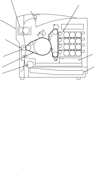
3.INTERNAL STRUCTURE
<Cross Sectional View >
4. Fusing Unit FU |
|
2. Belt Cartridge PU |
1. Toner Cartridge PU |
3. Cleaning Roller PU |
(K,Y,M,C) |
Exit Roller Assy PU |
|
Rear Cover Assy PU |
|
5. Transfer Base Assy PU
7. Transfer Roller Assy PU |
10. Laser Assy PU |
|
|
6. Transfer Unit PU |
8. Paper Tray PU |
|
|
9. Paper Feed Roller PU |
|
|
OPC Charger Roller PU |
|
Fig.1-3 |
No. |
Components Name |
Outline of Functions |
|
|
|
|
|
1 |
Toner Cartridge PU |
To contain the toners (K, Y, M, C) for developing. |
|
Each toner cartridge (K, Y, M, C) is independent. |
|||
|
|
||
|
|
|
|
2 |
Belt Cartridge PU |
To forms images, including the OPC belt. |
|
|
|
|
|
3 |
Cleaning Roller PU |
To clean and collect waste toner adhered to the transfer belt |
|
unit PU. |
|||
|
|
||
|
|
|
|
4 |
Fusing Unit FU |
To fuse by heat the toner images on the paper. |
|
|
|
|
|
5 |
Transfer Base Assy PU |
To transfer toner images from the transfer belt to the paper. |
|
|
|
|
|
6 |
Transfer Unit PU |
To form color images, maintaining the toner images of belt |
|
cartridge PU on the OPC belt. |
|||
|
|
||
7 |
Transfer Roller Assy PU |
To transfer the toner image of transfer belt to the paper. |
|
|
|||
|
|
|
|
8 |
Paper Tray PU |
To feed papers automatically. |
|
|
|
|
|
9 |
Paper Feed Roller PU |
To feed papers automatically from the paper cassette PU.. |
|
|
|
|
|
10 |
Laser Assy PU |
To generate a laser beam and scan over the OPC belt.. |
|
|
|
|
I-6
4.DESCRIPTION OF CONTROL PANEL
The printer control panel provides control of the printer including test printing, maintenance operations performed by the video controller and also the ones which are performed by the engine controller.
The Video Controller Mode and the Engine Controller Mode have some common functions. Under normal circumstances the functions in the Video controller mode will be used. Refer to Chapter V for further information.
4.1Video Controller Mode
The printer goes into the Video Controller Mode when the power is turned on by pressing the power button.
The Video Controller Mode supplies the general test printing and setting functions and some of the maintenance operations. If further engine settings are required, use the Engine Controller Mode.
4.2Engine Controller Mode
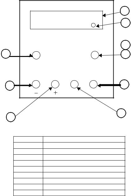
The printer goes into the Engine Controller Mode when power is turned on by pressing the power button at the same time as holding down the -, +, back. (Refer to Fig.1-4.)
Note:
This mode provides unique control panel display and operation functions which are completely different from the ones described on the actual control panel or in the user’s guide. Refer to Chapter V for detailed information.
I-7
|
|
|
1 |
|
|
|
2 |
|
|
|
3 |
4 |
Job |
Go |
5 |
|
Cancel |
|
|
6 |
|
|
7 |
|
BACK |
|
SET |
8 |
|
|
9 |
|
|
|
|
|
Fig.1-4 |
|
|
No. |
LED / Button Name |
||
1 |
LCD: 16 character by 2 lines |
||
2 |
Alarm LED |
|
|
3 |
Online LED |
|
|
4 |
Job Cancel Key |
|
|
5 |
Go Key |
|
|
6 |
- Key |
|
|
7 |
Set Key |
|
|
8 |
+ Key |
|
|
9 |
Back Key |
|
|
I-8
CHAPTER II
SPECIFICATIONS
CHAPTER II SPECIFICATIONS
1.RATING
 WARNING
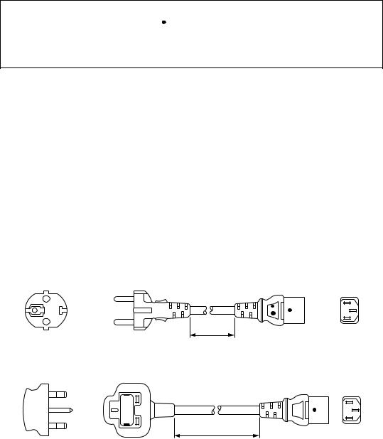
Use the power supply cable supplied with the printer, or a similar cable complying with the following specification (3-wire power cable with ground).
Use of an “out of specification” cable may result in an electric shock.
Destination |
Voltage (V) |
Frequency (Hz) |
Input Current (A) |
Power Cord (Piece) |
|
|
|
|
|
US / Canada |
120 |
50/60 |
11 |
1 |
|
|
|
|
|
Europe |
220 - 240 |
50/60 |
6 |
1* |
|
|
|
|
|
*For the model for Europe, the power supply cable depends on the country as follows;
Figure |
Rating |
Approval Agency |
Applicable Area |
|
|
|
|
|
|
A |
250VAC, 6A |
VDE, DEMKO, SEV |
Europe (Continent) |
|
|
|
|
||
B |
BS |
UK |
||
|
||||
|
|
|
|
Figure A: For Europe (Sample)
2.5m
Figure B: For UK
2.5m
Note:
For details of other power supply cables, refer to the parts reference list.
**For rating labels, refer to the Safety Instruction on Page vi.
II-1
2.GENERAL SPECIFICATIONS
2.1.Printing
Print method: Electrophotography by semiconductor laser beam scanning
Resolution: |
600 x 600 dpi |
|
|
|
600 x 600 dpi with CAPT (The resolution can be enhanced to 2400 dpi |
||
|
class by using CAPT (Color Advanced Photoscale Technology) and |
||
|
Brother exclusive HRC (High Resolution Control).) |
||
|
600 dpi class |
|
|
|
600 dpi class with CAPT |
||
Print speed: |
Standard: |
31 page/minute (A4/Letter-size in monochrome) |
|
|
|
8 page/minute (A4/Letter-size in full color) |
|
Warm-up: |
Less than 45 seconds at 22°C (71.6°F) |
||
First print: |
Monochrome mode: |
15 seconds (average) |
|
|
Full color mode: |
21 seconds (average) |
|
|
(when loading A4/Letter-size paper by face down print delivery from |
||
|
standard upper tray feed) |
||
Print media: |
Toner in a single-color single-component cartridge |
||
|
Life Expectancy: 10,000 single-sided pages/cartridge (Black) |
||
|
|
6,600 single-sided pages/cartridge (Cyan, |
|
|
|
Magenta, Yellow) |
|
Note: These figures are based on an average of 5% coverage of the printable area for one color using laser paper. The frequency of replacement will vary, depending on the complexity of the prints, the percentage of coverage, and the type of media. Transparencies, glossy coated paper and other special media will result in shortened consumable life.
Resident Printer Fonts:
<HP PCL, EPSON FX-850, and IBM Proprinter XL modes> 66 scalable fonts and 12 bitmapped fonts, 13 bar codes <BR-Script 3 mode>
35 scalable fonts
Machine Life: 240,000 pages or 5 years
Monthly (peak) volume: 30,000 pages
MTTR (Mean Time to Repair): 0.5 hours or less
II-2
2.2. Functions |
|
|
CPU: |
MIPS TMPR4955 (300 MHz) |
|
Emulation: |
Automatic emulation selection |
|
|
HP Color Printer (PCL5C) including HP LaserJet 4+ (PCL5e) and HP |
|
|
LaserJet 5 (PCL6 monochrome) |
|
|
BR-Script 3 (Adobe PostScript 3 compatible) |
|
|
HP-GL |
|
|
EPSON FX-850 |
|
|
IBM Proprinter XL |
|
Interface: |
IEEE 1284 parallel |
|
|
Universal Serial Bus 2.0 (High Speed) |
|
|
Ethernet 10/100 Base-TX |
|
RAM: |
Standard model: |
64Mbytes |
|
(Expandable up to 576Mbytes with SO-DIMM) |
|
The standard memory fitted can vary depending on the printer model and country.
Control panel: 6 buttons, 2 LEDs and a 16-column x 2 lines liquid crystal display Diagnostics: Self-diagnostic program
2.3.Electrical and Mechanical
Power source: U.S.A. and Canada: |
AC 120V, 50/60Hz |
||
|
Europe and Australia: AC 220 to 240V, 50/60Hz |
||
Power consumption: |
|
|
|
|
Printing: |
670W or less |
|
|
Standing by: |
200W or less |
|
|
Sleep: |
17W or less |
|
Noise: |
Printing: |
Lwad 6.6B or less (second power level) |
|
|
Standing by: |
Lwad 5.4B or less |
|
Temperature: |
Operating: |
|
10 to 32.5°C (50 to 90.5°F) |
|
Non Operating: |
5 to 35°C (41 to 95°F) |
|
|
Storage: |
|
0 to 35°C (38 to 95°F) |
Humidity: |
Operating: |
15 to 80% (non condensation) |
|
|
Storage: |
10 to 90% (non condensation) |
|
Dimensions (W x D x H): |
|
|
|
|
480 x 420 x 385 mm (18.9 x 16.5 x 15.2 inches) |
||
Weight: |
Approx. 31.5kg (69.4lbs.) |
||
II-3
 Loading...