

Page 1
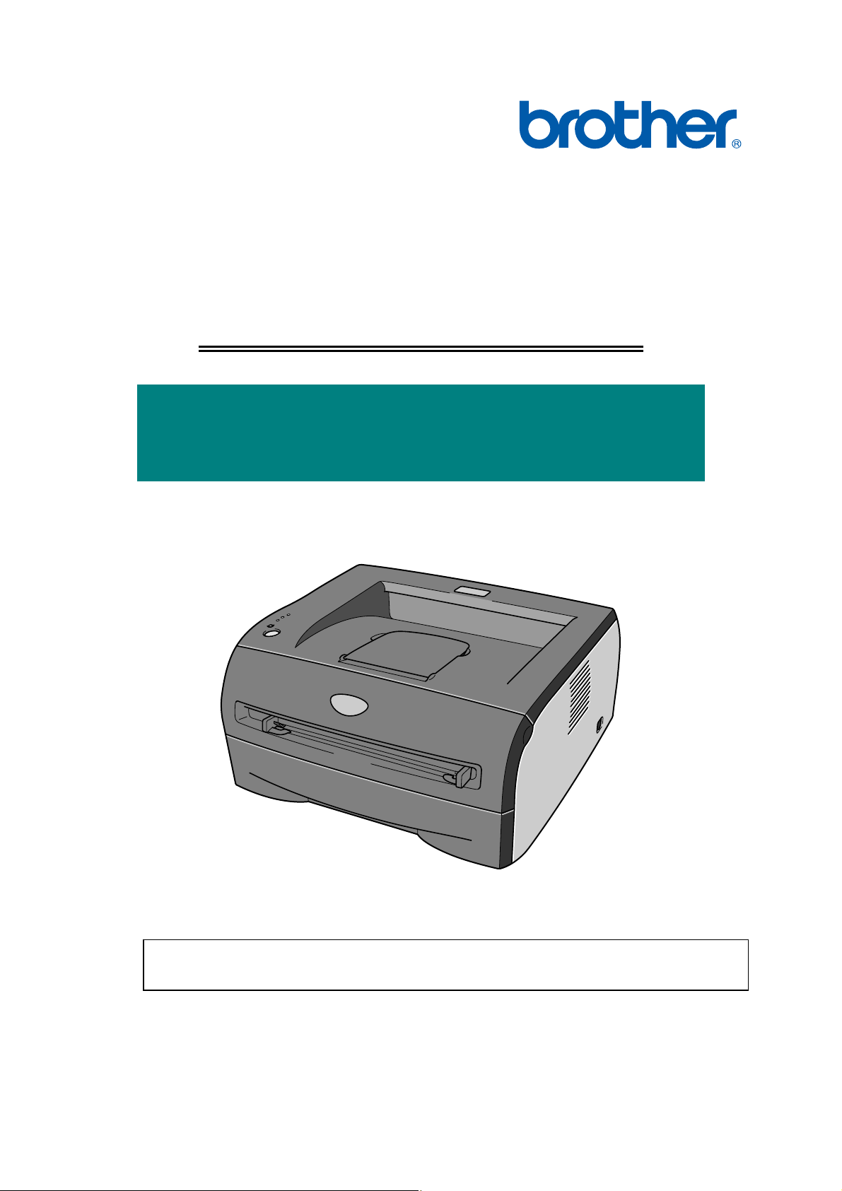
Brother Laser Printer
SERVICE MANUAL
MODEL:
HL-2030/2032/2040/2070N
Read this manual thoroughly before maintenance work.
Keep this manual in a convenient place for quick and easy reference at all times.
November 2004
SM-PRN054
(4)
Confidential
Page 2

© Copyright Brother Industries, Ltd. 2004
All rights reserved.
No part of this publication may be reproduced in any form or by any means without permission
in writing from the publisher.
Specifications are subject to change without notice.
Trademarks:
The Brother logo is a registered trademark of Brother Industries, Ltd.
Apple, the Apple Logo, Macintosh and TrueType are registered trademarks of Apple
Computer, Inc in the United States and other countries.
Epson is a registered trademark and FX-80 and FX-850 are trademarks of Seiko Epson
Corporation.
Hewlett Packard is a registered trademark and HP LaserJet 6P, 6L, 5P, 5L, 4, 4L 4P, III, IIIP,
II, and IIP are trademarks of Hewlett-Packard Company.
IBM, IBM PC, and Proprinter are registered trademarks of International Business Machines
Corporation.
Microsoft, MS-DOS, Windows and Windows NT are registered trademarks of Microsoft
Corporation in the U.S. and other countries.
ENERGY STAR is a U.S. registered mark.
Citrix and MetaFrame are registered trademarks of Citrix Systems, Inc. in the United State.
All other terms and brand and product names mentioned in this Service Manual are registered
trademarks of their respective companies.
Confidential
Page 3

PREFACE
This service manual contains basic information required for after-sales service of the laser
printer (hereinafter referred to as "this machine" or "the printer"). This information is vital to
the service technician to maintain the high printing quality and performance of the printer.
This service manual covers the HL-2030/2040/2070N printers.
This manual consists of the following chapters:
CHAPTER 1: GENERAL
Features, specifications, etc.
CHAPTER 2: INSTALLATION AND BASIC OPERATION
Installation conditions, Installation procedures, basic operation of the
printer etc.
CHAPTER 3: THEORY OF OPERATION
Basic operation of the mechanical system, the electrical system and the
electrical circuits and their timing information.
CHAPTER 4: DISASSEMBLY AND RE-ASSEMBLY
Procedures for disassembling and re-assembling the mechanical
system.
CHAPTER 5: PERIODIC MAINTENANCE
Periodical replacement parts, consumable parts, etc.
CHAPTER 6: ADJUSTMENTS AND UPDATING OF SETTING, REQUIRED AFTER
PARTS REPLACEMENT
CHAPTER 7: TROUBLESHOOTING
Reference values and adjustments, troubleshooting image defects,
troubleshooting malfunctions, etc.
CHAPTER 8: SERVICE SUPPORT SOFTWARE
Test print mode and Service menu mode, etc.
APPENDICES: PCB circuit diagrams, etc.
Information in this manual is subject to change due to improvement or redesign of the
product. All relevant information in such cases will be supplied in service information
bulletins (Technical Information).
A thorough understanding of this printer, based on information in this service manual and
service information bulletins, is required for maintaining its print quality performance and
for improving the practical ability to find the cause of problems.
i Confidential
Page 4

TABLE OF CONTENTS
REGULATION............................................................................................. vii
SAFETY INFORMATION............................................................................. ix
CHAPTER 1 GENERAL........................................................................... 1-1
1. FEATURES............................................................................................................. 1-1
2. OVERVIEW ............................................................................................................ 1-3
3. SPECIFICATIONS.................................................................................................. 1-4
3.1 Printing .............................................................................................................................1-4
3.2 Functions..........................................................................................................................1-5
3.3 Electronics and Mechanics...............................................................................................1-6
3.4 Service Information...........................................................................................................1-7
3.5 Network Connectivity........................................................................................................1-8
3.6 Paper................................................................................................................................1-9
3.6.1 Feedable paper...................................................................................................................1-9
3.6.2 Paper tray capacity............................................................................................................1-11
3.6.3 Print delivery......................................................................................................................1-11
3.7 Printable Area.................................................................................................................1-12
3.7.1 PCL5e/EPSON/IBM emulation..........................................................................................1-12
3.7.2 PCL6 emulation.................................................................................................................1-15
3.8 Print Speeds with Various Settings ................................................................................1-16
3.9 Toner Cartridge Weight Information...............................................................................1-17
4. SERIAL NO. DESCRIPTIONS.............................................................................. 1-18
CHAPTER 2 INSTALLATION AND BASIC OPERATION....................... 2-1
1. CONDITIONS REQUIRED FOR INSTALLATION................................................... 2-1
1.1 Power Supply....................................................................................................................2-1
1.2 Environment .....................................................................................................................2-1
1.3 System Requirements for Brother Printer Solution ..........................................................2-2
2. UNPACKING........................................................................................................... 2-3
3. INSTALL THE PRINTER......................................................................................... 2-4
3.1 For All Users.....................................................................................................................2-4
3.1.1 Install the drum unit assembly.............................................................................................2-5
3.1.2 Load paper in the paper tray...............................................................................................2-5
3.1.3 Print a test page..................................................................................................................2-6
3.2 For Windows® Users........................................................................................................2-7
3.3 For Macintosh Users ......................................................................................................2-11
4. PRINTING METHODS.......................................................................................... 2-13
4.1 Printing on Plain Paper, Recycled Paper or Transparencies from the Paper Tray ........2-13
4.2 Printing on Plain Paper, Recycled Paper, Bond Paper and Transparencies from
the Manual Feed Slot.....................................................................................................2-13
ii Confidential
Page 5

HL-2030/2040/2070N SERVICE MANUAL
4.3 Printing on Thick Paper, Card Stock, Labels, and Envelopes from the Manual Feed Slot
........................................................................................................................................2-15
4.4 Duplex Printing...............................................................................................................2-17
4.5 Paper Orientation for Manual Duplex Printing................................................................2-20
5. CONTROL PANEL OPERATION.......................................................................... 2-21
5.1 Control Panel Button & LED Functions (Printer Status) .................................................2-21
5.1.1 Control panel button..........................................................................................................2-21
5.1.2 LEDs .................................................................................................................................2-21
5.2 LED Indications ..............................................................................................................2-22
5.3 Service Call Indications ..................................................................................................2-24
5.4 Control Panel Button (Go button)...................................................................................2-25
5.5 Other Control Features...................................................................................................2-25
5.5.1 Print a test page................................................................................................................2-25
5.5.2 Print a printer settings page..............................................................................................2-26
5.5.3 Print fonts (For HL-2070N)................................................................................................2-26
6. NETWORK FUNCTIONS (FOR HL-2070N).......................................................... 2-27
6.1 LED Functions................................................................................................................2-27
6.2 Network Factory Default Setting (For HL-2070N)...........................................................2-27
6.3 Network Factory Default Setting with APIPA Protocol Disabled (For HL-2070N) ..........2-28
7. OPTIONAL PRINT SERVER................................................................................. 2-29
CHAPTER 3 THEORY OF OPERATION................................................. 3-1
1. ELECTRONICS ...................................................................................................... 3-1
1.1 General Block Diagram ....................................................................................................3-1
1.2 Main PCB Block Diagram.................................................................................................3-2
1.3 Main PCB .........................................................................................................................3-3
1.3.1 CPU.....................................................................................................................................3-3
1.3.2 USB interface......................................................................................................................3-5
1.3.3 IEEE 1284 interface ............................................................................................................3-6
1.3.4 Network interface................................................................................................................3-8
1.3.5 ROM....................................................................................................................................3-9
1.3.6 SDRAM .............................................................................................................................3-11
1.3.7 EEPROM...........................................................................................................................3-13
1.3.8 Reset circuit ......................................................................................................................3-13
1.3.9 Panel I/O...........................................................................................................................3-14
1.3.10 Video I/O ...........................................................................................................................3-15
1.3.11 Power supply.....................................................................................................................3-16
1.4 Power Supply..................................................................................................................3-17
1.4.1 Low-voltage power supply.................................................................................................3-17
1.4.2 High-voltage power supply................................................................................................3-18
2. MECHANICS ........................................................................................................ 3-19
2.1 Overview of Printing Mechanism....................................................................................3-19
2.2 Paper Transfer ...............................................................................................................3-20
2.2.1 Paper supply.....................................................................................................................3-20
2.2.2 Push-up function of paper tray..........................................................................................3-22
2.2.3 Paper registration..............................................................................................................3-24
2.2.4 Paper eject........................................................................................................................3-25
iii Confidential
Page 6

2.3 Drum Unit .......................................................................................................................3-25
2.3.1 Exposure drum..................................................................................................................3-25
2.3.2 Primary charger.................................................................................................................3-25
2.3.3 Transfer roller....................................................................................................................3-25
2.3.4 Cleaner..............................................................................................................................3-25
2.4 Toner Cartridge ..............................................................................................................3-26
2.4.1 Toner life end mode..........................................................................................................3-26
2.4.2 New toner detection mechanism.......................................................................................3-27
2.4.3 Counter reset during indication of “Toner Life End”..........................................................3-28
2.5 Print Process..................................................................................................................3-29
2.5.1 Charging............................................................................................................................3-29
2.5.2 Exposure stage.................................................................................................................3-29
2.5.3 Developing........................................................................................................................3-30
2.5.4 Transfer.............................................................................................................................3-31
2.5.5 Fixing stage....................................................................................................................... 3-31
2.6 Sensors ..........................................................................................................................3-32
CHAPTER 4 DISASSEMBLY AND RE-ASSEMBLY .............................. 4-1
1. SAFETY PRECAUTIONS....................................................................................... 4-1
2. DISASSEMBLY FLOW ........................................................................................... 4-2
3. DISASSEMBLY PROCEDURE............................................................................... 4-3
3.1 AC Cord............................................................................................................................4-3
3.2 Drum/Tone ASSY.............................................................................................................4-3
3.3 Paper Tray........................................................................................................................4-4
3.4 Rear Cover.......................................................................................................................4-5
3.5 Rear Chute Cover.............................................................................................................4-6
3.6 Side Cover L.....................................................................................................................4-7
3.7 Side Cover R....................................................................................................................4-7
3.8 Top Cover / Paper Stopper...............................................................................................4-8
3.9 Front Cover.....................................................................................................................4-10
3.10 Pickup Roller Holder ASSY ............................................................................................4-11
3.11 Fixing Unit.......................................................................................................................4-15
3.12 High-Voltage PS PCB ASSY..........................................................................................4-21
3.13 Main PCB .......................................................................................................................4-22
3.14 SW Key / Panel PCB......................................................................................................4-24
3.15 PS PCB Unit...................................................................................................................4-25
3.16 Laser Unit.......................................................................................................................4-28
3.17 Sub Chute ASSY............................................................................................................4-30
3.18 Link Lever.......................................................................................................................4-31
3.19 Tail Edge Actuator..........................................................................................................4-32
3.20 Regist Front Actuator / Regist Front Spring....................................................................4-32
3.21 Regist Sensor PCB ASSY..............................................................................................4-33
3.22 Regist Rear Actuator / Regist Rear Spring.....................................................................4-33
3.23 Fan Motor 60 Unit...........................................................................................................4-34
3.24 Toner LED PCB ASSY / LED Holder..............................................................................4-35
3.25 New Toner Actuator / New Toner Actuator Spring .........................................................4-36
3.26 New Toner Sensor..........................................................................................................4-36
iv Confidential
Page 7

HL-2030/2040/2070N SERVICE MANUAL
3.27 Cover Sensor................................................................................................................. 4-37
3.28 Toner Sensor PCB ASSY..............................................................................................4-37
3.29 Main Motor ASSY...........................................................................................................4-38
3.30 Develop Joint .................................................................................................................4-40
3.31 P/R Solenoid ASSY........................................................................................................4-40
3.32 F/R Solenoid ASSY........................................................................................................ 4-41
3.33 Main Frame L................................................................................................................. 4-43
3.34 Main Frame R ................................................................................................................4-44
4. PACKING ................................................................................................................4-45
5. LUBRICATION ........................................................................................................4-46
6. GUIDELINES FOR LEAD FREE SOLDER..............................................................4-47
7. SCREW TORQUE LIST ..........................................................................................4-50
8. HARNESS ROUTING..............................................................................................4-51
CHAPTER 5 PERIODIC MAINTENANCE............................................... 5-1
1. CONSUMABLE PARTS.............................................................................................5-1
1.1 Drum Unit......................................................................................................................... 5-1
1.2 Toner Cartridge................................................................................................................ 5-4
2. PERIODICAL REPLACEMENT PARTS....................................................................5-9
3. PERIODICAL CLEANING........................................................................................5-10
3.1 Cleaning the Inside of the Printer .................................................................................. 5-10
3.2 Cleaning the Corona Wire..............................................................................................5-10
3.3 Cleaning the Scanner Window ...................................................................................... 5-11
3.4 Cleaning the Electrical Terminals.................................................................................. 5-12
CHAPTER 6 ADJUSTMENTS AND UPDATING OF SETTINGS,
REQUIRED AFTER PARTS REPLACEMENT.................. 6-1
1. IF YOU REPLACE THE MAIN PCB ..........................................................................6-1
CHAPTER 7 TROUBLESHOOTING....................................................... 7-1
1. INTRODUCTION.......................................................................................................7-1
1.1 Initial Check......................................................................................................................7-1
1.2 Warnings for Maintenance Work .....................................................................................7-2
1.3 Identify the Problem......................................................................................................... 7-3
2. OPERATOR CALLS & SERVICE CALLS..................................................................7-4
2.1 Operator Calls.................................................................................................................. 7-4
2.2 Service Calls.................................................................................................................... 7-5
3. ERROR MESSAGE...................................................................................................7-6
3.1 List of Error Message.......................................................................................................7-6
3.2 Error Message in the Status Monitor............................................................................... 7-7
3.3 Error Message Printouts.................................................................................................. 7-8
4. PAPER PROBLEMS..................................................................................................7-9
4.1 Paper Loading Problems ................................................................................................. 7-9
v
Confidential
Page 8

4.2 Paper Jams.................................................................................................................... 7-10
4.2.1 Clearing jammed paper..................................................................................................... 7-10
4.2.2 Causes & countermeasures.............................................................................................. 7-14
4.3 Paper Feeding Problems............................................................................................... 7-15
5. SOFTWARE SETTING PROBLEMS.......................................................................7-17
6. MALFUNCTIONS ....................................................................................................7-20
7. IMAGE DEFECTS ...................................................................................................7-26
7.1 Image Defect Examples................................................................................................. 7-26
7.2 Diameter of Rollers ........................................................................................................7-26
7.3 Troubleshooting Image Defect....................................................................................... 7-27
7.4 Location of Grounding Contacts.................................................................................... 7-44
7.4.1 Drum unit ..........................................................................................................................7-44
7.4.2 Printer body & Paper tray.................................................................................................. 7-44
8. INCORRECT PRINTOUT........................................................................................7-45
9. NETWORK PROBLEM............................................................................................7-47
9.1 Installation Problem ....................................................................................................... 7-47
9.2 Printing Problem.............................................................................................................7-48
9.3 Protocol-Specific Troubleshooting.................................................................................7-49
CHAPTER 8 SERVICE SUPPORT SOFTWARE.................................... 8-1
1. CONTROL PANEL ....................................................................................................8-1
1.1 User Mode........................................................................................................................8-1
1.2 User Maintenance Mode..................................................................................................8-3
1.3 Service Mode...................................................................................................................8-4
2. HOW TO USE THE SELF-DIAGNOSTICS TOOLS ................................................8-12
2.1 Diagnostics.....................................................................................................................8-12
2.2 Printer Information .........................................................................................................8-14
3. NVRAM DEFAULT VALUE......................................................................................8-15
APPENDICES
1. MAIN PCB CIRCUIT DIAGRAM, HL-2030/2040 (1/3).............................................. A-1
2. MAIN PCB CIRCUIT DIAGRAM, HL-2030/2040 (2/3).............................................. A-2
3. MAIN PCB CIRCUIT DIAGRAM, HL-2030/2040 (3/3).............................................. A-3
4. MAIN PCB CIRCUIT DIAGRAM, HL-2070N (1/3).................................................... A-4
5. MAIN PCB CIRCUIT DIAGRAM, HL-2070N (2/3).................................................... A-5
6. MAIN PCB CIRCUIT DIAGRAM, HL-2070N (3/3).................................................... A-6
7. POINT TO POINT CONNECTION DIAGRAM.......................................................... A-7
8. LOW-VOLTAGE POWER SUPPLY PCB CIRCUIT DIAGRAM (100V).................... A-8
9. LOW-VOLTAGE POWER SUPPLY PCB CIRCUIT DIAGRAM (200V).................... A-9
10. HIGH-VOLTAGE POWER SUPPLY PCB CIRCUIT DIAGRAM............................. A-10
11. REPLACEMENT OF PINCH SPRING L AND PINCH SPRING R.......................... A-11
12. LOCATION OF COVER SPONGE L1 AND COVER SPONGE.............................. A-13
13. HOW TO ATTACH THE ANTI-STATIC BRUSH ALL............................................. A-14
vi
Confidential
 Loading...