

Page 1
Brother Laser Printer
SERVICE MANUAL
MODEL: HL-1850/1870N
Read this manual thoroughly before maintenance work.
Keep this manual in a convenient place for quick and easy reference at all times.
January 2002
SM-PRN031
Page 2

© Copyright Brother Industries, Ltd. 2002
All rights reserved.
No part of this publication may be reproduced in any form or by any means without permission
in writing from the publisher.
Specifications are subject to change without notice.
Trademarks:
The brother logo is a registered trademark of Brother Industries, Ltd.
Apple, the Apple Logo, and Macintosh are trademarks, registered in the United States and
other countries, and TrueType is a trademark of Apple computer, Inc.
Epson is a registered trademark and FX-80 and FX-850 are trademarks of Seiko Epson
Corporation.
Hewlett Packard is a registered trademark and HP LaserJet is a trademark of Hewlett Packard
Company.
IBM, IBM PC and Proprinter are registered trademarks of International Business Machines
Corporation.
Microsoft and MS-DOS are registered trademarks of Microsoft Corporation.
Windows is a registered trademark of Microsoft Corporation in the U.S. and other countries.
Page 3

HL-1850/1870N SERVICE MANUAL
PREFACE
This service manual contains basic information required for after-sales service of the laser
printer (hereinafter referred to as "this machine" or "the printer"). This information is vital to the
service technician to maintain the high printing quality and performance of the printer.
This service manual covers the HL-1850/1870N printers.
This manual consists of the following chapters:
CHAPTER 1: GENERAL
Features, specifications, etc.
CHAPTER 2: INSTALLATION AND BASIC OPERATION
Installation conditions, Installation procedures, basic operation of the printer
etc.
CHAPTER 3: THEORY OF OPERATION
Basic operation of the mechanical system, the electrical system and the
electrical circuits and their timing information.
CHAPTER 4: DISASSEMBLY AND RE-ASSEMBLY
Procedures for disassembling and re-assembling the mechanical system.
CHAPTER 5: PERIODIC MAINTENANCE
Periodical replacements parts, consumable parts, etc.
CHAPTER 6: TROUBLESHOOTING
Reference values and adjustments, troubleshooting image defects,
troubleshooting malfunctions, etc.
CHAPTER 7: HIDDEN FUNCTIONS
Professional menu mode and Service menu mode, etc.
APPENDICES: Serial No. descriptions, Drum life & page counter, Diameter / circumference
of rollers, Connection diagrams, PCB circuit diagrams, etc.
Information in this manual is subject to change due to improvement or redesign of the product.
All relevant information in such cases will be supplied in service information bulletins
(Technical Information).
A thorough understanding of this printer, based on information in this service manual and
service information bulletins, is required for maintaining its print quality performance and for
improving the practical ability to find the cause of problems.
i
Page 4

TABLE OF CONTENTS
TABLE OF CONTENTS
REGULATION.............................................................................................viii
SAFETY INFORMATION...............................................................................x
CHAPTER 1 GENERAL .......................................................................... 1-1
1. FEATURES .............................................................................................................1-1
2. OVERVIEW .............................................................................................................1-3
3. SPECIFICATIONS...................................................................................................1-4
3.1 Printing ............................................................................................................................. 1-4
3.2 Functions.......................................................................................................................... 1-5
3.3 Electrical and Mechanical ................................................................................................ 1-6
3.4 Network ............................................................................................................................ 1-7
3.5 Paper................................................................................................................................ 1-8
3.5.1 Feedable paper................................................................................................................... 1-8
3.5.2 Paper cassette capacity....................................................................................................1-10
3.5.3 Print delivery ..................................................................................................................... 1-10
3.6 Printing Area................................................................................................................... 1-11
3.6.1 PCL5e/EPSON/IBM emulation.......................................................................................... 1-11
3.6.2 PCL6/BR-Script3 emulation .............................................................................................. 1-14
CHAPTER 2 INSTALLATION AND BASIC OPERATION ...................... 2-1
1. CONDITIONS REQUIRED FOR INSTALLATION....................................................2-1
1.1 Power Supply ................................................................................................................... 2-1
1.2 Environment ..................................................................................................................... 2-1
®
1.3 System Requirements for Brother Printer Solution for Windows
2. UNPACKING ...........................................................................................................2-2
3. INSTALL THE PRINTER .........................................................................................2-3
3.1 For All Users .................................................................................................................... 2-3
3.1.1 Install the drum unit assembly ............................................................................................ 2-4
3.1.2 Load paper into the paper cassette .................................................................................... 2-4
3.1.3 Print a test page.................................................................................................................. 2-5
3.2 For Windows® Users ........................................................................................................ 2-6
3.3 For Macintosh Users ...................................................................................................... 2-10
4. PRINTING METHODS...........................................................................................2-12
4.1 Printing from the Paper Cassette ................................................................................... 2-12
4.2 Printing from Multi-purpose Tray .................................................................................... 2-12
4.2.1 Printing on envelopes (Face up printing) .......................................................................... 2-14
4.2.2 Printing on label, transparency, etc. ................................................................................. 2-15
4.3 Printing to the Face up Output Tray (Face up Printing) ................................................. 2-17
4.4 Printing on Both Sides of the Paper (Duplex Printing) ................................................... 2-17
4.5 Manual Feed ..................................................................................................................2-18
.................................... 2-1
ii
Page 5

HL-1850/1870N SERVICE MANUAL
5. CONTROL PANEL OPERATION...........................................................................2-19
5.1 Data LED Indications ..................................................................................................... 2-19
5.2 Panel Switches Functions .............................................................................................. 2-20
5.2.1 Go switch .......................................................................................................................... 2-20
5.2.2 Job Cancel switch............................................................................................................. 2-20
5.2.3 Reprint switch ................................................................................................................... 2-21
5.2.4 + & - switch ....................................................................................................................... 2-24
5.2.5 Set switch ......................................................................................................................... 2-24
5.2.6 Back switch....................................................................................................................... 2-24
5.3 LCD Display ................................................................................................................... 2-24
5.3.1 Backlights ......................................................................................................................... 2-25
5.3.2 Printer status messages ................................................................................................... 2-26
5.4 How to Use the Control Panel........................................................................................ 2-27
5.5 Control Panel Setting Menu ........................................................................................... 2-28
5.5.1 Information........................................................................................................................ 2-29
5.5.2 Paper ................................................................................................................................ 2-29
5.5.3 Quality............................................................................................................................... 2-30
5.5.4 Setup ................................................................................................................................ 2-30
5.5.5 Print menu......................................................................................................................... 2-31
5.5.6 Network............................................................................................................................. 2-34
5.5.7 Interface............................................................................................................................ 2-34
5.5.8 Reset menu....................................................................................................................... 2-35
5.5.9 Set IP address .................................................................................................................. 2-35
5.5.10 About emulation modes .................................................................................................... 2-36
5.5.11 List of factory settings ....................................................................................................... 2-36
5.6 Other Control Features .................................................................................................. 2-40
5.6.1 Sleep mode....................................................................................................................... 2-40
5.6.2 Inspection mode ............................................................................................................... 2-40
6. NETWORK BOARD OPERATION.........................................................................2-41
6.1 Installing the Network Board .......................................................................................... 2-41
6.2 Functions........................................................................................................................ 2-43
6.2.1 LED functions ................................................................................................................... 2-43
6.2.2 Factory default setting ...................................................................................................... 2-43
CHAPTER 3 THEORY OF OPERATION ................................................ 3-1
1. ELECTRONICS .......................................................................................................3-1
1.1 General Block Diagram .................................................................................................... 3-1
1.2 Main PCB Block Diagram................................................................................................. 3-2
1.3 Main PCB ......................................................................................................................... 3-3
1.3.1 ASIC.................................................................................................................................... 3-3
1.3.2 ROM.................................................................................................................................... 3-5
1.3.3 Flash ROM.......................................................................................................................... 3-6
1.3.4 SDRAM ............................................................................................................................... 3-7
1.3.5 Optional RAM...................................................................................................................... 3-9
1.3.6 PCI bus ............................................................................................................................. 3-10
1.3.7 EEPROM .......................................................................................................................... 3-11
1.3.8 Reset circuit ...................................................................................................................... 3-11
iii
Page 6

TABLE OF CONTENTS
1.3.9 Engine I/O......................................................................................................................... 3-12
1.3.10 Panel I/O ........................................................................................................................... 3-12
1.4 Engine PCB.................................................................................................................... 3-13
1.5 BR-net PCB.................................................................................................................... 3-13
1.6 Power Supply .................................................................................................................3-14
1.6.1 Low-voltage Power Supply ............................................................................................... 3-14
1.6.2 High-voltage Power Supply............................................................................................... 3-15
2. MECHANICS ......................................................................................................... 3-16
2.1 Overview of Printing Mechanism.................................................................................... 3-16
2.2 Paper Transfer ...............................................................................................................3-18
2.2.1 Paper supply..................................................................................................................... 3-18
2.2.2 Paper registration ............................................................................................................. 3-18
2.2.3 Paper eject........................................................................................................................ 3-19
2.2.4 Duplex printing.................................................................................................................. 3-19
2.3 Sensors .......................................................................................................................... 3-20
2.3.1 Cover sensors................................................................................................................... 3-20
2.3.2 Toner sensors................................................................................................................... 3-20
2.3.3 DX tray sensor / DX paper size sensor............................................................................. 3-21
2.3.4 Rear cover sensor ............................................................................................................ 3-21
2.3.5 Cassette sensor / Paper empty sensor............................................................................. 3-22
2.3.6 Paper eject sensor............................................................................................................ 3-22
2.4 Drum Unit ....................................................................................................................... 3-23
2.4.1 Photosensitive drum ......................................................................................................... 3-23
2.4.2 Primary charger ................................................................................................................ 3-23
2.4.3 Transfer roller ................................................................................................................... 3-23
2.4.4 Cleaner ............................................................................................................................. 3-23
2.5 Toner Cartridge ..............................................................................................................3-23
2.6 Print Process.................................................................................................................. 3-23
2.6.1 Charging ........................................................................................................................... 3-23
2.6.2 Exposure stage................................................................................................................. 3-24
2.6.3 Developing........................................................................................................................ 3-25
2.6.4 Transfer ............................................................................................................................ 3-25
2.6.5 Fixing stage ...................................................................................................................... 3-26
CHAPTER 4 DISASSEMBLY AND RE-ASSEMBLY.............................. 4-1
1. SAFETY PRECAUTIONS ........................................................................................4-1
2. DISASSEMBLY FLOW ............................................................................................4-2
3. DISASSEMBLY PROCEDURE ................................................................................4-3
3.1 AC Cord ........................................................................................................................... 4-3
3.2 Drum Unit ......................................................................................................................... 4-3
3.3 Paper Cassette ................................................................................................................ 4-4
3.4 Network Board (For HL-1870N only).............................................................................. 4-11
3.5 Top Cover ...................................................................................................................... 4-12
3.6 DX Feed ASSY............................................................................................................... 4-16
3.7 Rear Cover..................................................................................................................... 4-20
3.8 Rear Cover R & L / Side Cover R & L ............................................................................ 4-22
3.9 MP Cover ASSY............................................................................................................. 4-23
iv
Page 7

HL-1850/1870N SERVICE MANUAL
3.10 Process Unit Cover ASSY.............................................................................................. 4-25
3.11 Laser Unit....................................................................................................................... 4-26
3.12 Fixing Unit ...................................................................................................................... 4-27
3.13 Paper Pick-up Roller ASSY............................................................................................ 4-39
3.14 Feed MP Unit ................................................................................................................. 4-40
3.15 Drive Unit ....................................................................................................................... 4-42
3.16 Low-voltage Power Supply PCB ASSY.......................................................................... 4-47
3.17 Main PCB ASSY............................................................................................................. 4-48
3.18 Fan Motor / Fan Motor 60 .............................................................................................. 4-48
3.19 Base Plate...................................................................................................................... 4-49
3.20 Engine PCB ASSY / High-voltage Power Supply PCB ASSY........................................ 4-49
3.21 DX Sensor PCB ASSY................................................................................................... 4-51
3.22 Toner Sensor PCB Unit (Light Reception) ..................................................................... 4-52
3.23 Toner LED PCB Unit (Light Emission) ........................................................................... 4-52
3.24 Paper Feed Roller ASSY................................................................................................ 4-53
3.25 First Feed Roller ASSY .................................................................................................. 4-53
3.26 Exit Roller Unit................................................................................................................ 4-55
3.27 Harness Winding Form .................................................................................................. 4-57
4. PACKING ..............................................................................................................4-58
CHAPTER 5 PERIODIC MAINTENANCE............................................... 5-1
1. CONSUMABLE PARTS...........................................................................................5-1
1.1 Drum Unit ......................................................................................................................... 5-1
1.2 Toner Cartridge ................................................................................................................ 5-2
2. PERIODICAL REPLACEMENT PARTS...................................................................5-5
3. PERIODICAL CLEANING........................................................................................5-6
3.1 Cleaning the Printer Exterior ............................................................................................ 5-6
3.2 Cleaning the Drum Unit .................................................................................................... 5-6
3.3 Cleaning the Scanner Window ......................................................................................... 5-7
3.4 Cleaning the Electrical Terminals..................................................................................... 5-8
4. MTBF / MTTR..........................................................................................................5-9
CHAPTER 6 TROUBLESHOOTING ....................................................... 6-1
1. INTRODUCTION .....................................................................................................6-1
1.1 Initial Check...................................................................................................................... 6-1
1.2 Warnings for Maintenance Work ...................................................................................... 6-2
1.3 Identify the Problem .........................................................................................................6-3
2. OPERATOR CALLS & SERVICE CALLS ................................................................6-4
2.1 Operator Calls .................................................................................................................. 6-4
2.2 Service Calls .................................................................................................................... 6-6
3. PAPER PROBLEMS................................................................................................6-9
3.1 Paper Loading Problems.................................................................................................. 6-9
3.2 Paper Jams .................................................................................................................... 6-10
3.2.1 Clearing jammed paper..................................................................................................... 6-11
v
Page 8

TABLE OF CONTENTS
3.2.2 Causes & countermeasures.............................................................................................. 6-19
3.3 Paper Feeding Problems ............................................................................................... 6-20
4. SOFTWARE SETTING PROBLEMS .....................................................................6-22
5. MALFUNCTIONS ..................................................................................................6-25
6. IMAGE DEFECTS .................................................................................................6-31
6.1 Image Defect Examples ................................................................................................. 6-31
6.2 Troubleshooting Image Defect ....................................................................................... 6-32
6.3 Location of Grounding Contacts..................................................................................... 6-50
6.3.1 Drum unit .......................................................................................................................... 6-50
6.3.2 Printer body & Paper cassette .......................................................................................... 6-50
7. INCORRECT PRINTOUT ......................................................................................6-51
8. NETWORK PROBLEM..........................................................................................6-54
8.1 Installation Problem........................................................................................................ 6-54
8.2 Intermittent Problem ....................................................................................................... 6-55
8.3 TCP/IP Troubleshooting ................................................................................................. 6-56
8.4 UNIX Troubleshooting.................................................................................................... 6-56
8.5 Windows NT/LAN Server (TCP/IP) Troubleshooting ..................................................... 6-57
8.6 Windows 95/98/Me (or later) Peer to Peer Print (LPR) Troubleshooting ....................... 6-57
8.7 Windows 95/98/Me (or later) Peer to Peer (HP JetAdmin Compatible Method) Troubleshooting .....
....................................................................................................................................... 6-58
8.8 Windows 95/98/Me/NT 4.0/2000 (or later) Peer to Peer Print (NetBIOS) Troubleshooting ...
....................................................................................................................................... 6-58
8.9 Internet Print (TCP/IP) Troubleshooting ......................................................................... 6-58
8.10 Novell Netware Troubleshooting .................................................................................... 6-59
8.11 AppleTalk Troubleshooting ............................................................................................ 6-59
8.12 Apple TCP/IP Printing (System 8.6 or later)................................................................... 6-60
8.13 Web Browser Troubleshooting (TCP/IP)........................................................................ 6-60
9. INSPECTION MODE .............................................................................................6-61
9.1 Entering Inspection Mode .............................................................................................. 6-61
9.2 Sensor Check Mode....................................................................................................... 6-62
CHAPTER 7 HIDDEN FUNCTIONS ........................................................ 7-1
1. ENTERING HIDDEN FUNCTION MENU MODES ...................................................7-1
2. PROFESSIONAL MENU MODE..............................................................................7-2
2.1 Enabling and Disabling Professional Menu Mode............................................................ 7-2
2.2 Function Table ................................................................................................................. 7-3
3. SERVICE MENU MODE..........................................................................................7-7
3.1 Entering the Service Menu Mode ..................................................................................... 7-7
3.2 Function Table ................................................................................................................. 7-7
4. OTHER HIDDEN FUNCTION MENUS ....................................................................7-9
4.1 Hidden Function Menus Enabled by Pressing Switch(es) When Turning the Machine on ....
......................................................................................................................................... 7-9
4.2 Drum Life Reset Function ................................................................................................ 7-9
4.3 Parts life Reset Function .................................................................................................. 7-9
vi
Page 9

HL-1850/1870N SERVICE MANUAL
APPENDICES
1. CONNECTION DIAGRAM, HL-1850/1870N........................................................... A-1
2. MAIN PCB CIRCUIT DIAGRAM, HL-1850/1870N (1/6) .......................................... A-2
3. MAIN PCB CIRCUIT DIAGRAM, HL-1850/1870N (2/6) .......................................... A-3
4. MAIN PCB CIRCUIT DIAGRAM, HL-1850/1870N (3/6) .......................................... A-4
5. MAIN PCB CIRCUIT DIAGRAM, HL-1850/1870N (4/6) .......................................... A-5
6. MAIN PCB CIRCUIT DIAGRAM, HL-1850/1870N (5/6) .......................................... A-6
7. MAIN PCB CIRCUIT DIAGRAM, HL-1850/1870N (6/6) .......................................... A-7
8. ENGINE PCB CIRCUIT DIAGRAM, HL-1850/1870N (1/2) ..................................... A-8
9. ENGINE PCB CIRCUIT DIAGRAM, HL-1850/1870N (2/2) ..................................... A-9
10. NETWORK BOARD PCB CIRCUIT DIAGRAM, HL-1850/1870N.......................... A-10
11. LOW-VOLTAGE POWER SUPPLY PCB CIRCUIT DIAGRAM (100V) ................. A-11
12. LOW-VOLTAGE POWER SUPPLY PCB CIRCUIT DIAGRAM (200V) ................. A-12
13. HIGH-VOLTAGE POWER SUPPLY PCB CIRCUIT DIAGRAM ............................ A-13
14. SERIAL NO. DESCRIPTIONS.............................................................................. A-14
15. DIAMETER / CIRCUMFERENCE OF ROLLERS.................................................. A-16
16. PRINT SPEEDS WITH VARIOUS SETTINGS...................................................... A-17
17. HOW TO KNOW DRUM UNIT LIFE & PAGE COUNTER .................................... A-18
18. HOW TO USE THE SELF-DIAGNOSTICS TOOLS ............................................. A-23
19. NVRAM DEFAULT VALUE................................................................................... A-27
20. PAPER CASSETTE INFORMATION (FOR EUROPE ONLY)............................... A-28
21. GUIDELINES FOR LEAD FREE SOLDER (MAIN PCB ASSY) .......................... A-29
22. HOW TO REWRITE HL-1850/1870N FLASH ROM ............................................. A-30
INDEX
vii
Page 10

REGULATION
REGULATION
LASER SAFETY (110 - 120V MODEL ONLY)
This printer is certified as a Class 1 laser product under the US Department of Health and
Human Services (DHHS) Radiation Performance Standard according to the Radiation
Control for Health and Safety Act of 1968. This means that the printer does not produce
hazardous laser radiation.
Since radiation emitted inside the printer is completely confined within the protective
housing and external covers. the laser beam cannot escape form the machine during any
phase of user operation.
FDA REGULATIONS (110 - 120V MODEL ONLY)
The US Food and Drug Administration (FDA) has implemented regulations for laser
products manufactured on and after August 2, 1976. Compliance is mandatory for
products marketed in the United States. One of the following labels on the back of the
printer indicates compliance with the FDA regulations and must be attached to laser
products marketed in the United States.
The label for Japanese manufactured products
MANUFACTURED: K
BROTHER INDUSTRIES, LTD.
15-1, Naeshiro-cho, Mizuho-ku, Nagoya 467-8561,
Japan.
This product complies with FDA radiation performance
standards, 21 CFR Subchapter J.
The label for Chinese manufactured products
MANUFACTURED: C
BROTHER Corporation (Asia) Ltd.
Shenzen Buji Nan Ling Factory
Gold Garden Ind., Nan Ling Village, Buji, Rong Gang,
Shenzen, CHINA
This product complies with FDA radiation performance
standards, 21 CFR Subchapter J.
Caution
Use of controls, adjustments or performance of procedures other than those specified in
this manual may result in hazardous radiation exposure.
viii
Page 11
HL-1850/1870N SERVICE MANUAL
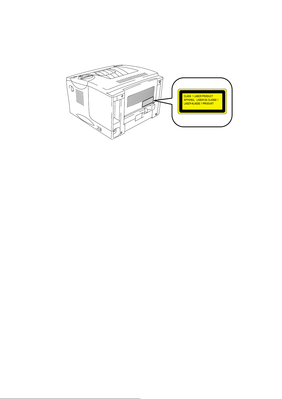
IEC 825 (220-240V MODEL ONLY)
This printer is a Class 1 laser product as defined in IEC 825 specifications. The label
shown below is attached in countries where required.
This printer has a laser diode which emits invisible laser radiation in the Laser Unit. The
Laser Unit should not be opened without disconnecting the two connectors connected with
the AC power supply and laser unit. Since the variable resistor in the laser unit is adjusted
in accordance with the standards, never touch it.
Caution
Use of controls, adjustments or performance of procedures other than those specified in
this manual may result in hazardous radiation exposure.
For Finland and Sweden
LUOKAN 1 LASERLAITE
KLASS 1 LASER APPARAT
Varoitus! Laitteen käyttäminen muulla kuin tässä käyttöohjeessa mainitulla tavalla saattaa
altistaa käyttäjän turvallisuusluokan 1 ylittävälle näkymättömälle lasersäteilylle.
Varning Om apparaten används på annat sätt än i denna Bruksanvisning specificerats,
kan användaren utsättas för osynlig laserstrålning, som överskrider gränsen för laserklass
1.
ix
Page 12
SAFETY INFORMATION
CAUTION FOR LASER PRODUCT (WARNHINWEIS FUR LASER DRUCKER)
CAUTION: When the machine during servicing is operated with the cover open, the
CAUTION: In case of any trouble with the laser unit, replace the laser unit itself. To
ACHTUNG: Im Falle von Störungen der Lasereinheit muß diese ersetzt werden. Das
<Location of the laser beam window>
SAFETY INFORMATION
regulations of VBG 93 and the performance instructions for VBG 93 are
valid.
prevent direct exposure to the laser beam, do not try to open the enclosure
of the laser unit.
Gehäuse der Lasereinheit darf nicht geöffnet werden, da sonst
Laserstrahlen austreten können.
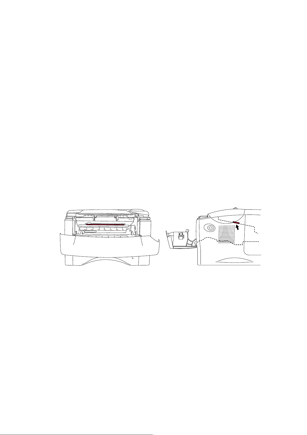
ADDITIONAL INFORMATION
When servicing the optical system of the printer, be careful not to place a screwdriver or
other reflective object in the path of the laser beam. Be sure to take off any personal
accessories such as watches and rings before working on the printer. A reflected beam,
though invisible, can permanently damage the eyes.
Since the beam is invisible, the following caution label is attached on the laser unit.
x
Page 13

CAUTION
ADVARSEL
VARNING
VARO!
ADVARSEL
ATTENTION
VORSICHT
ATENCIÓN
INVISIBLE LASER RADIATION WHEN OPEN AND INTERLOCK DEFEATED.
AVOID DIRECT EXPOSURE TO BEAM. CLASS 3B LASER PRODUCT.
USYNLIG LASER STRÅLING NÅR KABINETLÅGET STÅR ÅBENT.
UNGDÅ DIREKTE UDSÆTTELSE FOR STRÅLING. KLASSE 3B LASER.
OSYNLIG LASERSTRÅLNING NÄR DENNA DEL ÄR ÖPPNAD OCH SPÄRRAR
ÄR URKOPPLADE. STRÅLEN ÄR FARLIG. KLASS 3B LASER APPARAT.
AVATTAESSA JA SUOJALUKITUS OHITETTAESSA OLET ALTTIINA
NÄKYMÄTTÖMÄLLE LASERSÄTEILYLLE. ÄLÄ KATSO SÄTEESEEN. LUOKAN
3B LASERLAITE.
USYNLIG LASERSTRÅLING.UNNGÅ DIREKTE KONTAKT MED LASERENHETEN
NÅR TOPPDEKSELET ER ÅPENT. KLASSE 3B LASERPRODUKT.
RADIATIONS LASER INVISIBLES QUANDOUVERT ET VERROUILLAGE ENLEVE.
EVITER EXPOSITIONS DIRECTES AU FAISCEAU. PRODUIT LASER CLASSE 3B.
UNSICHTBARE LASERSTRAHLUNG WENN ABDECKUNG
GEÖFFENT UND SICHERHEITSVERRIEGELUNG
ÜBERBRÜCKT. NICHT DEM STRAHL AUSSETZEN.
SICHERHEITSKLASSE 3B.
RADIACIÓN LASER INVISIBLE CUANDO SE ABRE
LA TAPA Y EL INTERRUPTOR INTERNO ESTÁ
ATASCADO. EVITE LA EXPOSICIÓN DIRECTA
DE LOS OJOS. PRODUCTO LASER CLASE 3B.
HL-1850/1870N SERVICE MANUAL
xi
Page 14
SAFETY INFORMATION
DEFINITIONS OF WARNINGS, CAUTIONS AND NOTES
The following conventions are used in this service manual:
Indicates warnings that must be observed to prevent possible personal injury.
!
Indicates cautions that must be observed to service the printer properly or prevent damage
to the printer.
NOTE:
Indicates notes and useful tips to remember when servicing the printer.
**Listed below are the various kinds of WARNING messages included in this manual.
WARNING
CAUTION:
WARNING
Always turn off the power switch and unplug the power cord from the power outlet
before accessing any parts inside the printer.
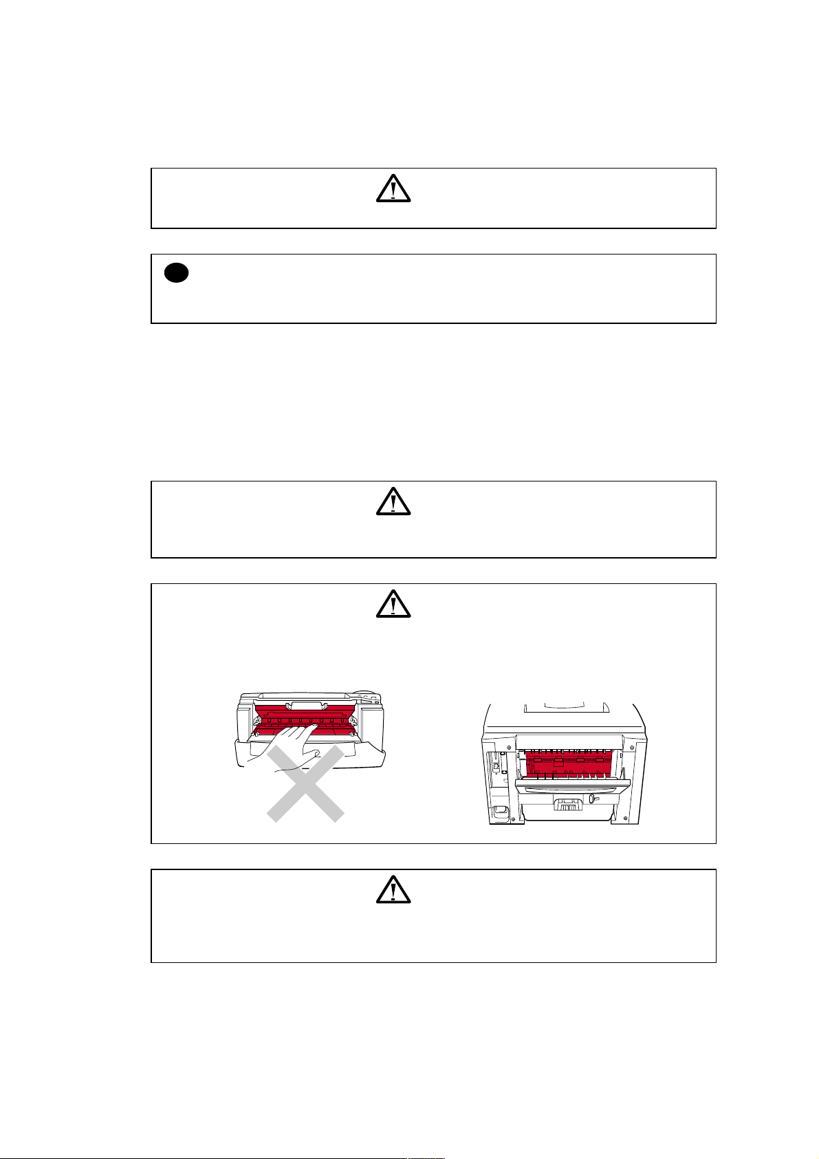
WARNING
Some parts inside the printer are extremely hot immediately after the printer is used.
When opening the front cover or rear cover to access any parts inside the printer,
never touch the red colored parts shown in the following figures.
WARNING
If you analyze malfunctions with the power plug inserted into the power outlet,
special caution should be exercised even if the power switch is OFF because it is a
single pole switch.
xii
Page 15

HL-1850/1870N SERVICE MANUAL
xiii
Page 16

CHAPTER 1 GENERAL
1. FEATURES
This printer has the following features;
High Resolution and Fast Print Speed
True 600 x 600 dots / true 300 x 300 dots per inch (dpi) and 2400 x 600 dots per inch (dpi) for
graphics with microfine toner and up to 18 pages per minutes (ppm) print speed for A4 and 19
pages per minutes (ppm) print speed for Letter paper.
Versatile Paper Handling
The printer loads paper automatically from the paper cassette. The paper cassette can hold
A4, letter, B5 (ISO), B5 (JIS), A5, B6 (ISO), A6, Executive and Legal sizes of paper. The
manual feed slot allows manual paper loading sheet by sheet so you can use a variety of types
and sizes of paper.
HL-1850/1870N SERVICE MANUAL
Front Operation
Basic operation of the printer can be controlled from the control panel.
Enhanced Printing Performance and User-Friendly Operation for Windows
The dedicated printer driver for Microsoft Windows 95/98/Me, Windows NT 4.0 and
Windows
install them into your Windows
unique compression mode to enhance printing speed in Windows
2000/XP are available on the CD-ROM supplied with your printer. You can easily
system using our installer program. The driver supports our
applications and allows you
to choose various printer settings including toner save mode, custom paper size, sleep mode,
gray scale adjustment, resolution, water mark and many layout functions. You can easily
setup these print options through the Printer Setup Menu.
Printer Status Monitor with Bi-directional Parallel Interface
The printer driver can monitor the status of your printer using bi-directional parallel
communications. IEEE-1284 bi-directional parallel printer cable is recommended.
The printer status monitor program can show the current status of your printer. When printing,
the animated dialog box appears on your computer screen to show the current printing
process. If an error occurs, a dialog box will appear to let you know what to correct. If you
have turned on the interactive Help (Windows
95/98 only) you can get visual guidance on
your PC screen on the actions in the event of certain printer errors.
Quick Print Setup
The Quick Print Setup is a convenient utility to allow you to make changes to frequently used
driver settings easily without having to open the printer properties selection box every time. It
is launched automatically when this printer driver is selected. You can change the settings by
clicking on the icon with the right mouse button.
Enhanced Memory Management
The printer provides its own data compression technology in its printer hardware and the
supplied printer driver software, which can automatically compress graphic data and font data
efficiently into the printers memory. You can avoid memory errors and print most full page 600
dpi graphic and text data, including large fonts, with the standard printer memory.
1-1
Page 17

CHAPTER 1 GENERAL
USB Interface (for Windows
98 / 2000/XP, iMac and Power Macintosh)
The printer can be connected using the Universal Serial Bus (USB) interface to a PC or Mac
which has a USB interface. Drivers that allow you to use the USB port are provided on the
CD-ROM supplied with the printer.
Popular Printer Emulation Support
These printers support the following printer emulation modes;
HP LaserJet (PCL6), PostScript Level 3 language emulation (Brother BR-Script Level 3),
Epson FX-850 and IBM Proprinter XL.
When you use DOS application software or Windows version 3.0 or earlier, you can use any
of these emulations to operate the HL-1850/1870N printers. The printers also support autoemulation switching between HP, Brother BR-Script 3 and Epson or HP, BR-Script 3 and IBM.
If you want to set the printer emulation, you can do it using the Remote Printer Console
Program.
High Resolution Control & Advanced Photoscale Technology
High Resolution Control (HRC) technology provides clear and crisp printouts. Use this function
to get smooth text print quality.
Advanced Photoscale Technology (APT) enables the printer to print graphics in 256
grayscales, producing nearly photographic quality. Use this function when you want to print
photographic images.
Environment-Friendly
<Economy Printing Mode>
This feature will cut your printing cost by saving toner. It is useful for obtaining draft copies for
proof-reading. You can select the 50% toner saving economy mode through the Windows
printer driver supplied with your printer.
<Sleep Mode (Power Save Mode)>
Sleep mode automatically reduces power consumption when the printer is not in use for a
certain period of time. The printer consumes less than 12W when in sleep mode.
<Low Running Cost>
Since the toner cartridge is separate from the drum unit, you need to replace only the toner
cartridge after printing around 6,500 pages at 5% coverage for A4 paper for the standard
cartridge, which is both cost effective and ecologically friendly.
Bar Code Print
The printer can print the following 11 types of bar codes;
Code 39
•
Code 128
•
Interleaved 2 of 5
•
Codabar
•
US-PostNet
•
ISBN
•
UPC-A
•
UPC-E
•
EAN-8
•
EAN-13
•
EAN-128
•
Network Feature (for HL-1870N only)
The Brother printer has built in multi protocol network capability as standard. This allows
multiple host computers to share the printer on a 10/100Mbit Ethernet network. Any users can
print their jobs as if the printer was directly connected to their computer. Users on Windows
®
95/98/Me, Windows® NT, Windows® 2000/XP, UNIX, Novell, Apple Macintosh, LAN server and
OS/2 Warp server computer simultaneously can access this printer. For further information,
see the Network Users Guide supplied with the printer.
1-2
Page 18
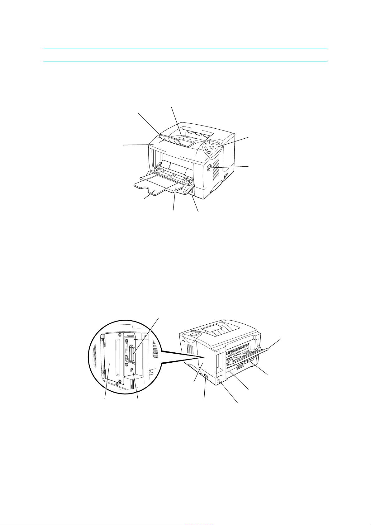
2. OVERVIEW
<Front View>
HL-1850/1870N SERVICE MANUAL
Extension flap
Front cover
Multi-purpose tray extension
<Rear View>
Face down output tray
Multi-purpose tray
Control panel
Cover release button
Paper cassette
Fig. 1-1
Parallel interface connector
Face up output tray
Face up tray extension
Paper adjustment lever
Interface cover
Duplex tray
USB connectorPCB access plate
Power switch
Fig. 1-2
AC power inlet
for duplex printing
1-3
Page 19

CHAPTER 1 GENERAL
3. SPECIFICATIONS
3.1 Printing
Print method Electrophotography by semiconductor laser beam scanning
Laser Wavelength: 780 nm
Output: 5mW max
Resolution HQ1200 (for Windows
®
95/98/Me, WindowsNT® 4.0, Windows
2000/XP, and Mac OS)
600 dpi (for Windows
®
95/98/Me, WindowsNT® 4.0, Windows
2000/XP, DOS and Mac OS)
300 dpi (for Windows
®
95/98/Me, WindowsNT® 4.0, Windows
2000/XP, and Mac OS)
Print quality Normal printing mode
Economy printing mode (up to 25% and 50% toner saving)
Print speed Normal: Up to 18 pages/minute (A4)
UP to 19 pages/minute (Letter-size paper)
Duplex printing: Up to 8.5 pages/minute*
(when loading A4 or Letter-size paper from the standard paper
cassette.)
Warm-up Max. 20 seconds at 23°C (73.4°F)
First print Max. 12 seconds
(when loading A4 or Letter-size paper from the standard paper
cassette.)
Print media Toner cartridge
Life expectancy: 6,500 pages/cartridge
(when printing A4 or Letter-size paper at 5% print coverage)
®
®
®
Developer Drum unit
Life expectancy: 20,000 pages/drum unit
*NOTE:
Print speed varies depending on the paper size or media type. For details, refer to APPENDIX
16 PRINT SPEEDS WITH VARIOUS SETTINGS.
1-4
Page 20

3.2 Functions
CPU Fujitsu MB86834 100MHz
HL-1850/1870N SERVICE MANUAL
Emulation Brother Printing Solution for Windows
Automatic emulation selection among HP LaserJet (PCL level 6),
Brother BR-Script Level 3, EPSON FX-850 or IBM Proprinter XL
Printer driver <PCL Driver>
Windows
95/98/Me, Windows NT 4.0, Windows® 2000/XP driver,
supporting Brother Native Compression mode
<PS Driver>
PPD file driver for Windows
95/98/Me, Windows NT 4.0, Windows®
2000/XP driver and Macintosh driver
<Others>
• iMac, Power Macintosh with USB printer driver
• Optional Macintosh driver available for System 6.0.7 or higher
Interface • Bi-directional parallel
• Universal Serial Bus (USB)
• 10/100 BaseTX Ethernet network interface (optional for HL-1850)
• Optional IrDA
Memory HL1850: 16 Mbytes
HL1870N: 32 Mbytes
Expandable up to 136 Mbytes for HL1850 and 144 Mbytes for
HL1870N by installing an industry standard DIMM*
Control Panel • Display LCD: 1 line, 16 digit, 3 color
LED: 1 LED
• Buttons 7 keys
Diagnostics Self-diagnostic program
*NOTE:
The DIMM must have the following specifications;
Type: 100 pin
Access time: 60 nsec - 80 nsec
Capacity: 16, 32, 64, 128 Mbyte
Height: 35.0 mm (1.38 inches) or less
Output: 32 bit or 36 bit (independent of parity)
1-5
Page 21

CHAPTER 1 GENERAL
3.3 Electrical and Mechanical
Power source U.S.A. and Canada: AC 110 to 120V, 50 Hz/60 Hz
Power consumption Printing (average): 410 W or less
10 W or less (for HL-1870N)
Noise Printing: 50dB A or less
Temperature Operating: 10 to 32.5°C (50 to 90.5°F)
Humidity Operating: 20 to 80% (non condensing)
Dimensions 425 x 424 x 275 mm
(W x D x H) (16.7 x 16.7 x 10.8 inches)
Europe and Australia: AC 220 to 240V, 50 Hz/60 Hz
Standing by: 70 W or less
Sleep*: 9 W or less (for HL-1850)
Standing by: 30dB A or less
Non operating: 0 to 40°C (38 to 104°F)
Storage: -20 to 40°C (-4 to 104°F)
Storage: 10 to 85% (non condensing)
A4 lower paper cassette installed: 425 x 424 x 384 mm
(16.7 x 16.7 x 15.1 inches)
Weight Approx. 14.5 kg (32.2 lb.) including the drum unit.
Approx. 18.7 kg (41.6 lb.) including the drum unit and the optional
lower tray unit.
*NOTE:
• The power consumption figure quoted for sleep mode is when the fan has stopped.
1-6
Page 22

3.4 Network
Type / Speed 10/100 Base TX Ethernet
Protocols TCP/IP (RARP, BOOTP, DHCP, NetBIOS, WINS, LPR/LPD, Port9100,
Management • Web Based Management (HTTPD)
Firmware update Flash ROM based for Network module
HL-1850/1870N SERVICE MANUAL
Automatic negotiation
POP3/SMTP, SMB, User definable port, IPP, FTP, TELNET, SNMP,
HTTP, TFTP), Netware IPX/SPX (Bindey and NDS), Appletalk,
DLC/LLC, NetBEUI, DEC LAT, Banyan VINES
• BRAdmin Professional (using TCP/IP protocol and IPX/SPX)
• SNMP, MIB II as well as Brother private MIB
• TELNET command console (NIC only)
• HP JetAdmin compatible
• BRCONFIG DOS Utility (NIC only, needs Netware network)
• Front Panel Configuration (if the printer has LCD panel)
• Can be upgraded using TFTP
• Can be upgraded using IPX/SPX
• Easy upgrade using Brother BRAdmin utility
Supplied software • BRAdmin Professional management utility (for Windows
Windows
• Port driver for Windows
2000/XP
LPR port driver (for Windows
NT 4.0/Windows
2000/XP)
95/98, WindowsNT 4.0/Windows
95/98 only)
NetBIOS port driver
SMTP port driver
95/98,
1-7
Page 23
CHAPTER 1 GENERAL
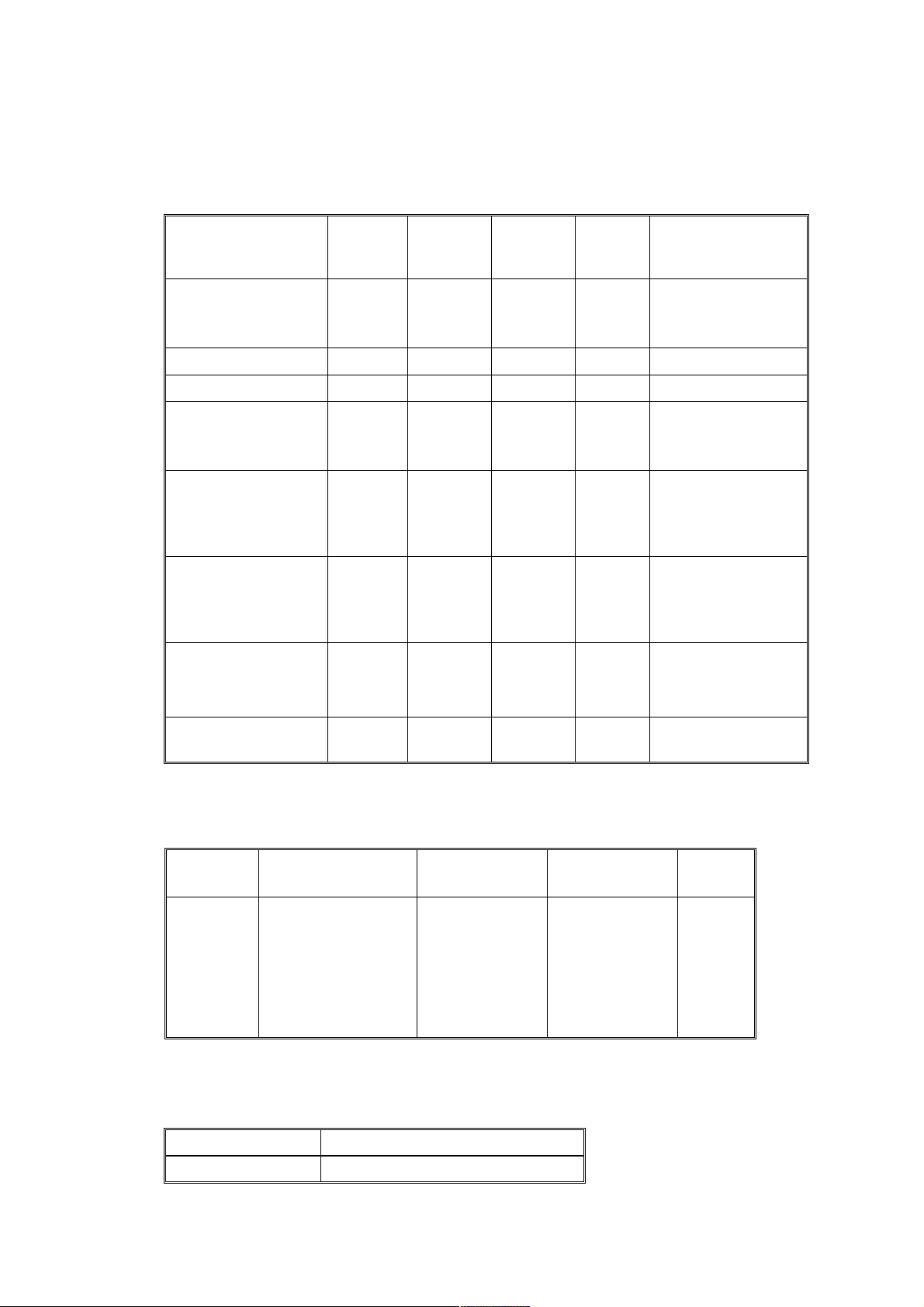
3.5 Paper
3.5.1 Feedable paper
(1) Paper type
Paper type
Plain paper
60 g/m
2
to 105 g/m
(16 to 28 lbs.)
Recycled paper
Bond paper
Thick paper
105 g/m
2
to 161 g/m
(28 to 43 lbs.)
Transparency
Label
Envelope
Card
2
2
Upper
paper
tray
Multi-
purpose
tray
Optional
lower
tray
Duplex
printing
○○○○
○○○○
○
○
○
Up to 10
sheets
○
Only A4
or Letter
size
○
Only A4
or Letter
size
○
○
Select the paper
type from the
printer driver
Plain paper
Plain paper
Bond paper
Thick paper
or thicker paper
Transparencies
Plain paper
Envelopes
or Env.Tick
or Env.Thin
Thick paper
or thicker paper
(2) Paper size
Upper
paper tray
A4, Letter, Legal,
8.5x13 in., B5 (JIS),
B5 (ISO), Executive,
Paper size
A5, A6, B6
(3) Other paper specifications
<Paper cassette>
Basis weight 60 to 105 g/m
Multi-purpose
tray
Width:
70 to 216 mm
(2.75 to 8.5 in.)
Length:
116 to 356 mm
(4.57 to 14.0 in.)
Cut sheet
2
(16 to 28 lb.)
1-8
Optional lower
tray
A4, Letter,
Legal, B5 (JIS),
B5 (ISO),
Executive, A5
Duplex
printing
A4,
Letter,
Legal
Page 24
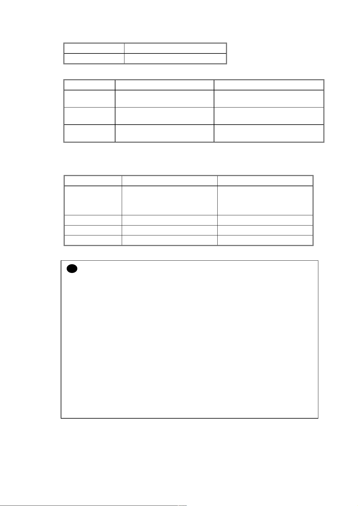
HL-1850/1870N SERVICE MANUAL
Caliper 0.08 to 0.13 mm (0.003 to 0.005 in.)
Moisture content 4% to 6% by weight
<Multi-purpose tray>
Cut sheet Envelope
2
Basis weight 60 to 161 g/m
(16 to 43 lb.) 75 to 90 g/m2 (20 to 24 lb.)
single thickness
Caliper 0.08 to 0.2 mm (0.003 to 0.008 in.) 0.084 to 0.14 mm (0.003 to 0.005 in.)
single thickness
Moisture
4% to 6% by weight 4% to 6% by weight
content
(4) Recommended paper
Europe USA
Plain paper Xerox Premier 80 g/m
Xerox Business 80 g/m
IGEPA X-Press 80 g/m
2
2
2
Recycled paper Steinbis Recycling Copy 80 g/m
Xerox 4200DP 20 lb
Champion Paper One 20 lb
Hammermill Laser Paper 24 lb
2
Transparency 3M CG3300 3M CG 3300
Label Avery laser label L7163 Avery laser label #5160
CAUTION:
!
When you are choosing print media, be sure to follow the information given below to prevent
any paper jams, print quality problems or printer damage;
• It is recommended to use long-grained paper for the best print quality. If short-grained
paper is being used, it might be the cause of paper jams.
• Use neutral paper. Do not use acid paper to avoid any damage to the drum unit.
• Avoid using coated paper such as vinyl coated paper.
• Avoid using preprinted or highly textured paper.
• It is recommended to use labels or transparencies which are designed for use in laser
printers.
• Avoid feeding labels with the carrier sheet exposed, or the printer will be damaged.
• Before loading paper with holes such as organizer sheets, be sure to fan the stack well.
• Do not use organizer sheets that are stuck together. The glue that is used might caused
damaged to the printer.
• When printing on the back of pre-printed paper, if the paper is curled, be sure to straighten
the paper as much as possible.
• Different types of paper should not be loaded at the same time in the paper cassette to
avoid any paper jams or misfeeds.
1-9
Page 25
CHAPTER 1 GENERAL
3.5.2 Paper cassette capacity
Paper
Capacity
3.5.3 Print delivery
(1) Face down output tray
capacity: Maximum 150 sheets (80 g/m
(2) Face up output tray
capacity: Maximum 50 sheets (80 g/m
NOTE:
Face-down: Delivery with the printed face of the paper downwards.
Face-up: Delivery with the printed face of the paper upwards.
Upper
paper tray
250 sheet
(80 g/m
2
or 20 lbs.)
face down only
face up only
Multi-purpose
tray
100 sheets
2
(80 g/m
or 20 lbs.)
Legal: 30
8.5x13 in.: 30
Label stock: 10
Optional lower tray
250 sheets
(80 g/m
2
)
2
)
2
or 20 lbs.)
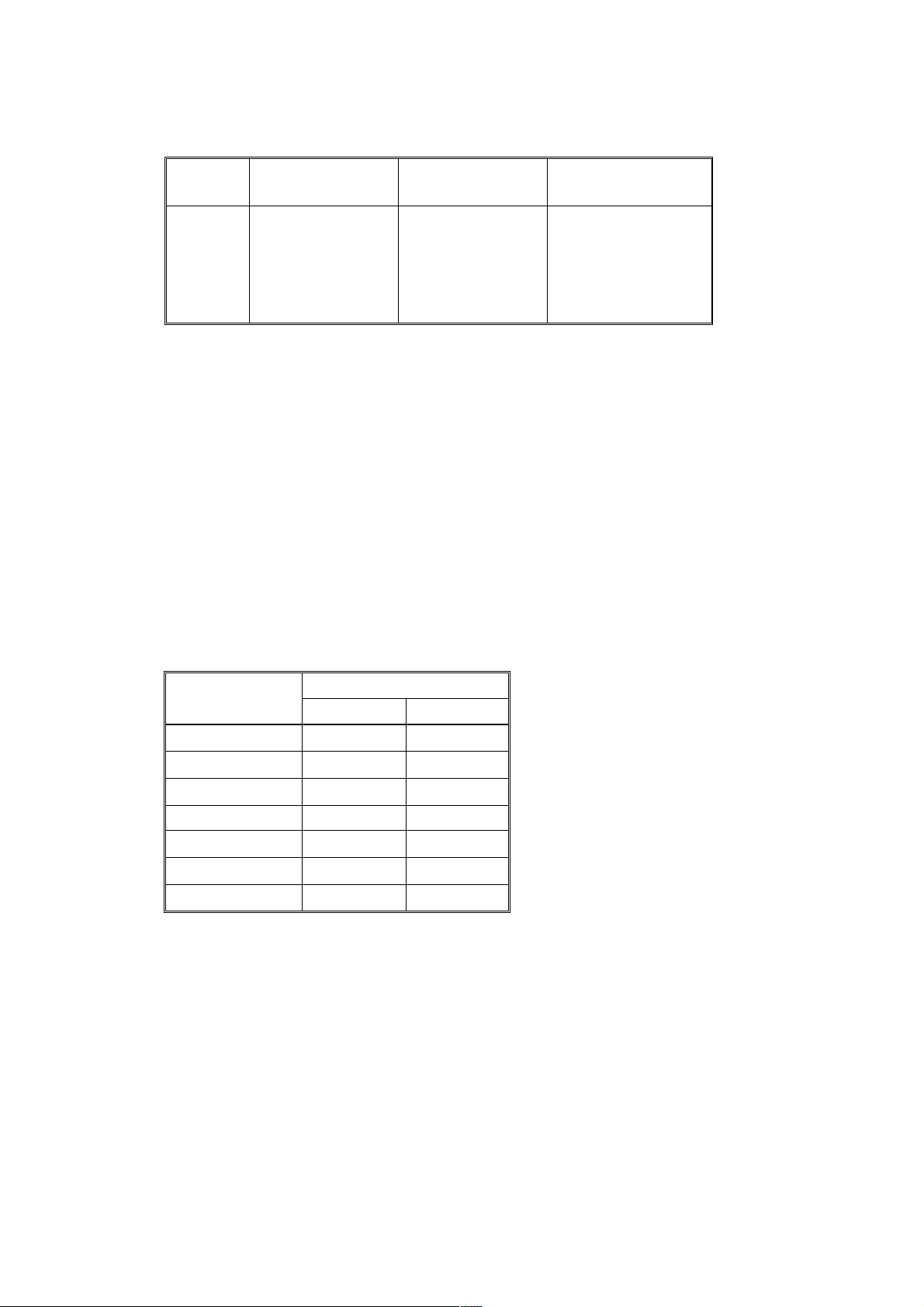
(3) We recommend the following print methods (output tray) for each paper media type.
Paper output
Media type
Face down Face up
Plain paper
Thick paper
Recycled paper
Transparency
Label
Envelope
Card
○○
○
○
○
○
○
○
○
1-10
Page 26
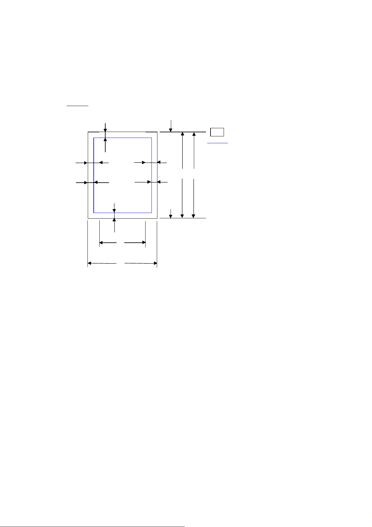
3.6 Printable Area
3.6.1 PCL5e/EPSON/IBM emulation
The figure below shows the printable area each emulation guarantees when printing on Portrait
and Landscape.
Portrait
ʝ
G
HL-1850/1870N SERVICE MANUAL
ʝ
F
Physical page
Printable area
Logical page
ʝ
ʝ
E
ʝ
G
E
ʝ
B
ʝ
D
ʝ
G
ʝ
B
ʝ
D
ʝ
F
Physical page length
Maximum logical page length
DIstance from edge of physical page to
edge of logical page
ʝ
F
ʝ
G
ʝ
C
ʝ
A
ʝ
ʝ
ʝ
ʝ
ʝ
ʝ
ʝ
1-11
Page 27

CHAPTER 1 GENERAL
The table below shows the printable areas when printing on Portrait for each paper size.
Size A B C D E F G
Letter
Legal
Executive
A 4
A 5
A 6
B 5 (JIS)
B 5 (ISO)
B 6
COM10
MONARCH
C 5
DL
NOTE:
• The paper sizes indicated here should confirm to the nominal dimensions specified by JIS
except B5 (ISO).
• The dot size is based on 300 dpi resolution.
215.9 mm
8.5
(2,550 dots)
215.9 mm
8.5
(2,550 dots)
184.15 mm
7.25
(2,175 dots)
210.0 mm
8.27
(2,480 dots)
148.5 mm
5.85
(1,754 dots)
105.0 mm
4.13
(1,240 dots)
182.0 mm
7.1
(2,130 dots)
176.0 mm
6.93
(2,078 dots)
125.0 mm
4.92
(1,476 dots)
104.78 mm
4.125
(1,237 dots)
98.43 mm
3.875
(1,162 dots)
162.0 mm
6.38
(1,913 dots)
110.0 mm
4.33
(1,299 dots)
279.4 mm
11.0
(3,300 dots)
355.6 mm
14.0
(4,200 dots)
266.7 mm
10.5
(3,150 dots)
297.0 mm
11.69
(3,507 dots)
210.0 mm
8.27
(2,480 dots)
148.5 mm
5.85
(1,754 dots)
257.0 mm
10.11
(3,033 dots)
250.0 mm
9.84
(2,952 dots)
176.0 mm
6.93
(2,078 dots)
241.3 mm
9.5
(2,850 dots)
190.5 mm
7.5
(2,250 dots)
229.0 mm
9.01
(2,704 dots)
220.0 mm
8.66
(2,598 dots)
203.2 mm
8.0
(2,400 dots)
203.2 mm
8.0
(2,400 dots)
175.7 mm
6.92
(2,025 dots)
198.0 mm
7.79
(2,338 dots)
136.5 mm
5.37
(1,612 dots)
93.0 mm
3.66
(1,098 dots)
170.0 mm
6.69
(2,007 dots)
164.0 mm
6.46
(1,936 dots)
164.0 mm
4.44
(1,334 dots)
92.11 mm
3.63
(1,087 dots)
85.7 mm
3.37
(1,012 dots)
150.0 mm
5.9
(1,771 dots)
98.0 mm
3.86
(1,157 dots)
279.4 mm
11.0
(3,300 dots)
355.6 mm
14.0
(4,200 dots)
266.7 mm
10.5
(3,150 dots)
297.0 mm
11.69
(3,507 dots)
210.0 mm
8.27
(2,480 dots)
148.5 mm
5.85
(1,754 dots)
257.0 mm
10.11
(3,033 dots)
250.0 mm
9.84
(2,952 dots)
176.0 mm
6.93
(2.078 dots)
241.3 mm
9.5
(2,850 dots)
190.5 mm
7.5
(2,250 dots)
229.0 mm
9.01
(2,704 dots)
220.0 mm
8.66
(2,598 dots)
6.35 mm
0.25
(75 dots)
Ç
6.35 mm
0.25
(75 dots)
6.01 mm
0.24
(71 dots)
Ç
Ç
Ç
Ç
Ç
6.35 mm
0.25
(75 dots)
Ç
6.01 mm
0.24
(71 dots)
Ç
0 mm
0 mm
0 mm
0 mm
0 mm
0 mm
0 mm
0 mm
0 mm
0 mm
0 mm
0 mm
0 mm
4.2 mm
0.16
(50 dots)
4.2 mm
0.16
(50 dots)
4.2 mm
0.16
(50 dots)
4.2 mm
0.16
(50 dots)
4.2 mm
0.16
(50 dots)
4.2 mm
0.16
(50 dots)
4.2 mm
0.16
(50 dots)
4.2 mm
0.16
(50 dots)
4.2 mm
0.16
(50 dots)
4.2 mm
0.16
(50 dots)
4.2 mm
0.16
(50 dots)
4.2 mm
0.16
(50 dots)
4.2 mm
0.16
(50 dots)
1-12
Page 28
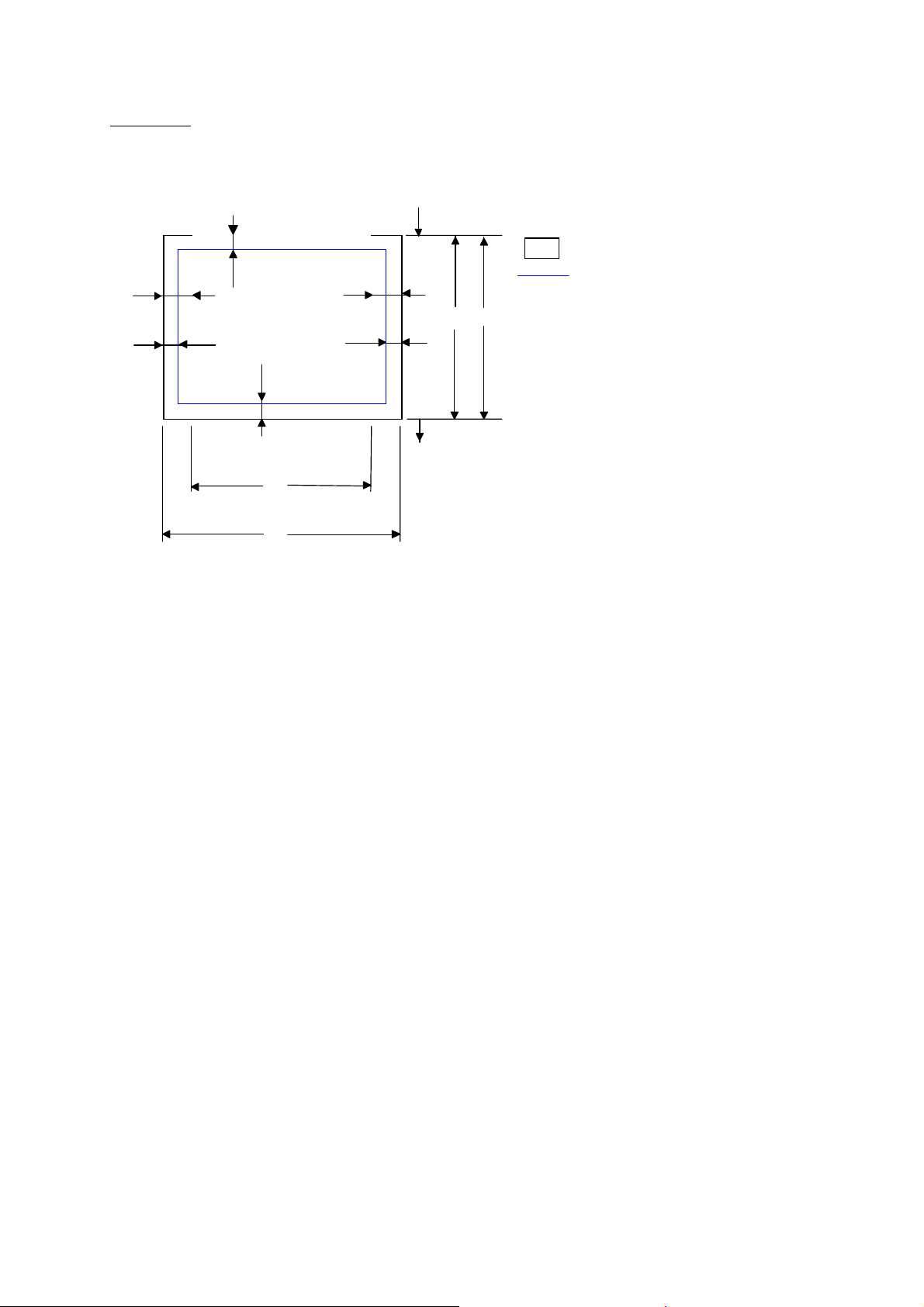
Landscape
HL-1850/1870N SERVICE MANUAL
ʝ
ʝ
G
F
Physical page
Printable area
ʝ
ʝ
E
ʝ
G
E
ʝ
ʝ
B
D
ʝ
G
Logical page
B Physical page le ngth
D Maximum logical page length
ʝ
ʝ
ʝ
ʝ
ʝ
F D ista nce from edge of physical
ʝ
G
ʝ
C
ʝ
A
ʝ
F
page to edge of logical page
ʝ
1-13
Page 29

CHAPTER 1 GENERAL
The table below shows the printable areas when printing on Landscape for each paper size.
Size A B C D E F G
Letter
Legal
Executive
A 4
A 5
A 6
B 5 (JIS)
B 5 (ISO)
B 6
COM10
MONARCH
C 5
DL
NOTE:
• The paper sizes indicated here should confirm to the nominal dimensions specified by JIS
except B5 (ISO).
• The dot size is based on 300 dpi resolution.
279.4 mm
11.0
(3,300 dots)
355.6 mm
14.0
(4,200 dots)
266.7 mm
10.5
(3,150 dots)
297.0 mm
11.69
(3,507 dots)
210.0 mm
8.27
(2,480 dots)
148.5 mm
5.85
(1,754 dots)
257.0 mm
10.11
(3,033 dots)
250.0 mm
9.84
(2,952 dots)
176.0 mm
6.93
(2,078 dots)
241.3 mm
9.5
(2,850 dots)
190.5 mm
7.5
(2,250 dots)
229 mm
9.01
(2,704 dots)
220 mm
8.66
(2,598 dots)
215.9 mm
8.5
(2,550 dots)
215.9 mm
8.5
(2,550 dots)
184.15 mm
7.25
(2,175 dots)
210.0 mm
8.27
(2,480 dots)
148.5 mm
5.85
(1,754 dots)
105.0 mm
4.13
(1,240 dots)
182.0 mm
7.1
(2,130 dots)
176.0 mm
6.93
(2,078 dots)
125.0 mm
4.92
(1,476 dots)
104.78 mm
4.125
(1,237 dots)
98.43 mm
3.875
(1,162 dots)
162 mm
6.38
(1,913 dots)
110 mm
4.33
(1,299 dots)
269.3 mm
10.6
(3,180 dots)
345.5 mm
13.6
(4,080 dots)
256.6 mm
10.1
(3,030 dots)
287.0 mm
11.2
(3,389 dots)
200.0mm
7.87
(2,362 dots)
138.5 mm
5.45
(1,636 dots)
247.0 mm
9.72
(2,916 dots)
240.0 mm
9.44
(2,834 dots)
166.4 mm
6.55
(1,960 dots)
231.1 mm
9.1
(2,730 dots)
180.4 mm
7.1
(2,130 dots)
219.0 mm
8.62
(2,586 dots)
210.0 mm
8.26
(2,480 dots)
215.9 mm
8.5
(2,550 dots)
215.9 mm
8.5
(2,550 dots)
184.15 mm
7.25
(2,175 dots)
210.0 mm
8.27
(2,480 dots)
148.5 mm
5.85
(1,754 dots)
105.0 mm
4.13
(1,240 dots)
182.0 mm
7.1
(2,130 dots)
176.0 mm
6.93
(2,078 dots)
125.0 mm
4.92
(1,476 dots)
104.78 mm
4.125
(1,237 dots)
98.43 mm
3.875
(1,162 dots)
162 mm
6.38
(1,913 dots)
110 mm
4.33
(1,299 dots)
5.0 mm
0.2
(60 dots)
Ç
5.0 mm
0.2
(60 dots)
4.8 mm
0.19
(59 dots)
Ç
Ç
Ç
Ç
Ç
5.0 mm
0.2
(60 dots)
Ç
4.8 mm
0.19
(59 dots)
Ç
0 mm
0 mm
0 mm
0 mm
0 mm
0 mm
0 mm
0 mm
0 mm
0 mm
0 mm
0 mm
0 mm
4.2 mm
0.16
(50 dots)
4.2 mm
0.16
(50 dots)
4.2 mm
0.16
(50 dots)
4.2 mm
0.16
(50 dots)
4.2 mm
0.16
(50 dots)
4.2 mm
0.16
(50 dots)
4.2 mm
0.16
(50 dots)
4.2 mm
0.16
(50 dots)
4.2 mm
0.16
(50 dots)
4.2 mm
0.16
(50 dots)
4.2 mm
0.16
(50 dots)
4.2 mm
0.16
(50 dots)
4.2 mm
0.16
(50 dots)
3.6.2 PCL6/BR-Script3 emulation
You can not print within 4.2 mm (50dots in 300 dpi mode) on all four sides of the paper.
1-14
Page 30

HL-1850/1870N SERVICE MANUAL
CHAPTER 2 INSTALLATION AND BASIC OPERATION
1. CONDITIONS REQUIRED FOR INSTALLATION
1.1 Power Supply
• The source voltage must stay within ±10% of the rated voltage shown on the rating plate.
• The power cord, including extensions, should not exceed 5 meters (16.5 feet).
• Do no share the same power circuit with other high-power appliances, particularly an air
conditioner, copier or shredder. If it is unavoidable that you must use the printer with these
appliances, it is recommended that you use an isolation transformer or a high-frequency
noise filter.
• Use a voltage regulator if the power source is not stable.
1.2 Environment
• The printer should be installed near a power outlet, which is easily accessible.
• The room temperature is maintained between 10°C and 32.5°C. The relative humidity is
maintained between 20% and 80%.
• The printer should be used in a well ventilated room.
• Place the printer on a flat, horizontal surface.
• Keep the printer clean. Do not place the printer in a dusty place.
• Do not place the printer where the ventilation hole of the printer is blocked. Keep
approximately 100 mm (4 inches) between the ventilation hole and the wall.
• Do not place the printer where it is exposed to direct sunlight. Use a blind or a heavy
curtain to protect the printer from direct sunlight when the printer is unavoidably set up near
a window.
• Do not place the printer near devices that contain magnets or generate magnetic fields.
• Do not subject the printer to strong physical shocks or vibrations.
• Do not expose the printer to open flames or salty or corrosive gasses.
• Do not place objects on top of the printer.
• Do not place the printer near an air conditioner.
• Keep the printer horizontal when carrying.
• Do not cover the slots in the side cover.
1.3 System Requirements for Brother Printer Solution for Windows
Check the following system requirements to setup and operate the printer using Brother
Printing Solution for Windows
Operating system Computer / Processor Memory
Windows
95
Windows 98
Windows Me
Windows NT 4.0
Windows 2000/XP
:
486DX / 66MHz or higher processor 24MB
Pentium 150MHz or higher processor 32MB
Pentium 150MHz or higher processor 32MB
Pentium 150MHz or higher processor 24MB
Pentium 133MHz or higher processor 64MB
2-1
Page 31

CHAPTER 2 INSTALLATION AND BASIC OPERATION
2. UNPACKING
When unpacking the printer, check to see that all of the following components are included in
the carton.
Paper cassette
Printer
Drum unit
(with Toner cartridge included)
CD-ROM
Fig. 2-1
NOTE:
Components may vary depending on the country.
Documents
AC cord
2-2
Page 32

HL-1850/1870N SERVICE MANUAL
3. INSTALL THE PRINTER
You need to implement hardware setup and driver installation to use the printer.
Firstly, identify the Operating System on your computer. (Windows
4.0, Windows® 2000/XP and Macintosh)Then, purchase the appropriate interface cable
(Parallel, USB or Network) for your computer. Most existing parallel cables support bidirectional communication, but some might have an incompatible pin assignment or may not be
IEEE 1284-compliant.
The installation programs for the hardware setup and driver installation are contained on the
supplied CD-ROM.
3.1 For All Users
For Windows
Turn on the PC power. Insert the supplied CD-ROM into the CD-ROM drive. The opening screen will
appear automatically
NOTE:
If the opening screen does not appear; click Start and select Run. Then, enter the CD-drive
letter and type \START.EXE (for example: D:\START.EXE).
users
®
95/98/Me, Windows NT
®
Select the language you want.
The main menu screen appears.
Click the Initial Setup icon. You can view the Initial Setup instructions.
For Macintosh users
(1) Turn on the Macintosh. Insert the CD-ROM into the CD-ROM drive.
(2) Click the Initial Setup & Maintenance Tutorial icon.
Select the language you want.
Click the Initial Setup icon. You can view the Initial Setup instructions.
2-3
Page 33

CHAPTER 2 INSTALLATION AND BASIC OPERATION
3.1.1 Install the drum unit assembly
(1) Press the cover release button, and then open the front cover.
Unpack the drum unit assembly. Rock it from side to side 5 or 6 times to distribute the toner evenly
inside the assembly.
Fig. 2-2
Install the drum unit assembly into the printer.
Fig. 2-3
Close the front cover.
3.1.2 Load paper into the paper cassette
(1) Pull the paper cassette completely out of the printer.
While pressing the paper guide release lever, slide the adjusters to fit the paper size. Check that they
locate correctly into the slots.
Paper guide release lever
Universal guide
release lever
Fig. 2-4
NOTE:
For Legal or 8.5 x 13 in. paper, press the universal guide release lever to extend the rear of the
Paper cassette.
2-4
Page 34

HL-1850/1870N SERVICE MANUAL
Load paper into the paper cassette. Check that the paper is flat in the tray and below the maximum
paper mark.
Fig. 2-5
Re-install the paper cassette into the printer.
3.1.3 Print a test page
(1) Make sure the printer power switch is off. Connect the AC power cord to the printer. Do
not connect the interface cable.
Plug the AC power cord into an AC outlet. Turn the power switch on.
After the printer has finished warming up, the READY message appears.
Extend the tray
extension flap
READY
Data
Back
Reprint
Set
Job cancel
Go
Fig. 2-6
Press the Go switch. The printer prints a test page. Check that the test page printed correctly.
2-5
Page 35

CHAPTER 2 INSTALLATION AND BASIC OPERATION
Follows the instructions for your operating system and interface cable type.
3.2 For Windows Users
Connect the printer to the PC & install the driver
For parallel interface cable users
(1) Click Connect the Interface cable and install the printer driver / utilities.
(2) Select the parallel interface cable.
(3) Turn the printer power switch off.
Connect the interface cable to your PC, then connect it to the printer.
Turn the printer power switch on.
NOTE:
If Add New Hardware Wizard appears, click the Cancel button.
Click the Next button.
Click the Finish button. The setup is now complete.
For USB interface cable users
Start installing the driver before connecting the USB interface cable to the printer. If it has
been already connected, remove it.
NOTE:
When the Add New Hardware Wizard appears on the PC, click the Cancel button.
(1) Click Connect the interface cable and install the printer driver / utilities.
(2) Select the USB cable.
Click the Next button, and then click the OK button.
Make sure the printer power switch is on.
Connect the USB interface cable to the PC, and then connect it to the printer.
NOTE:
If The file brUSGcfg.exe on Brother USB Printer class message appears, click the
Browse button, and then select the CD-ROM drive. Select the DRIVER\WIN98MEUSB
directory, and then click the OK button.
Restart the computer.
For Windows
For Windows
printer port.
®
98/Me users: The setup is now complete.
®
2000/XP users: Follow the instructions below for setting the PC
2-6
Page 36

®
For Windows
2000/XP users only
Click Start, Setting and then Printers.
Fig. 2-7
Select the Brother HL-1850/1870N series (copy2) icon.
HL-1850/1870N SERVICE MANUAL
Fig. 2-8
Click on the File menu, and then select Set as Default printer. The setup is now complete.
For network users
• For connecting the printer to a network, it is recommended to contact the system
administrator prior to installation.
• For the administrator: Configure the printer referring to the following instructions.
• For installing the driver on the PC, refer to the following instructions once the administrator
has configured the printer.
1. For the administrator
Install the BRAdmin Professional Configuration utility
The BRAdmin Professional software provides sophisticated network and printer management
capabilities for Brother and non-Brother products. By identifying potential problems before
they arise, and by addressing important IT requirements such as streamlined printer
configuration, mass configuration and enterprise-wide upgrades, the BRAdmin Professional
software plays an important role in printer network management.
(1) Insert the CD-ROM.
(2) Select the appropriate language.
(3) Click the Install Software icon.
(4) Select BRAdmin Professional. Install the BRAdmin Professional utility referring to the on-
screen instructions.
2-7
Page 37

CHAPTER 2 INSTALLATION AND BASIC OPERATION
Driver Deployment Wizard: Useful utility for peer-to-peer users
Use the Brother Driver Deployment Wizard software to automate the installation of Brother
networked printers in a TCP/IP environment. The Wizard can create an Executable file that
can be sent to other network users, when run, the Executable file installs the appropriate
printer driver and network printing software.
To access the Driver Deployment Wizard:
(1) Insert the CD-ROM supplied with the printer.
(2) Click the Install Software icon and select the Driver Deployment Wizard.
2. Installing the driver
(1) Click the Connect the interface cable and install the printer driver / utilities.
Select the Network interface.
Turn the printer power switch off.
Connect the cable to your printer, and then connect it to a free port on your hub.
Turn the printer power switch on.
Click the Next button.
Select the Network shared printer or the Brother peer-to-peer network printer, and then click the
Next button.
Select the network connection style and follow the instructions below:
3. For Network shared printer users
Select the appropriate printer Queue or Sharename
(1) Select the current printers queue, and then click the OK button.
(2) Once the appropriate queue is specified, the printer driver will be installed.
(3) The setup is now completed.
Fig. 2-9
2-8
Page 38

HL-1850/1870N SERVICE MANUAL
4. For Brother Peer-to-Peer network printer users (LPR-recommended Peer-to-Peer
printing method)
Configuring the LPR port
®
<For Windows
(1) Select LPR (Recommended) and then click the Next button.
(2) Enter a unique port name (ex. BLP1), and then click the OK button.
(3) Specify the printers IP address (or click the Browse button to see a list of printers), and
click the OK button.
95/98/Me users>
Fig. 2-10
(4) Click the Finish button and restart the PC. After the PC has restarted, setup is complete.
<For Windows NT
®
4.0/ Windows ® 2000/XP users>
(1) Select LPR (Recommended), and then click the Next button.
NOTE:
If the following screen appears, insert the Windows NT
Fig. 2-11
®
4.0 CD-ROM into the CD-ROM drive.
(2) Click the Next button.
(3) Enter the printers IP address and the port name BINARY_P1, then click the Next button.
(4) Click the Finish button and restart the PC. After your PC has restarted, setup is complete.
2-9
Page 39

CHAPTER 2 INSTALLATION AND BASIC OPERATION
5. For Brother Peer-to-Peer network printer users (NetBIOS)
Configuring the NetBIOS port
(1) Select NetBIOS, and click the Next button.
(2) Enter a unique port name (ex. BNT1), and then click the OK button.
(3) Enter the path name (or click the Browse button to see a list of printers), and then click the
OK button.
(4) Click the Finish button and restart your PC. After the PC has restarted, setup is complete.
3.3 For Macintosh Users
For USB interface cable users
Connect the printer to the Macintosh and install the BR-Script PPD File
(1) Click Connect the interface cable & Install the driver/utility.
(2) Make sure the printer power switch is ON.
(3) Connect the USB interface cable to the Macintosh
(4) Follow the instructions on the screen.
(5) Open the Macintosh HD icon.
(6) For Mac
Open the Apple LaserWriter Software folder.
For Mac
Open the Utilities folder.
®
OS 8.6 to 9.04 Users; Open the Apple Extras folder.
®
OS 9.1 to 9.2 Users; Open the Applications.( Mac
®
, and then connect it to the printer.
®
OS 9) folder.
(7) Open the Desktop Printer Utility icon.
(8) Select Printer (USB), and then click the OK button.
(9) Click the Changebutton in PostScript Printer Description (PPD) file. Select Brother HL-
1850/1870N series, and then click the Select button.
(10) Click the Changebutton in USB Printer Selection. Select HL-1850/1870N series, and
then click the OK button.
(11) Click the Createbutton.
(12) Enter your printer name (HL-1850/1870N series), and then click the Save button.
(13) Select Quit from the File menu.
2-10
Page 40

HL-1850/1870N SERVICE MANUAL
For network users
Connect the printer to the Macintosh & install the BR-Script PPD file
(1) Double click the BR-Script PPD Installer icon and then follow the instructions on the
screen.
(2) Turn the printer power switch off.
(3) Connect the cable to the printer, and then connect it to a free port on the hub.
(4) Turn the printer power switch on.
(5) Open the Chooser from the Apple Menu on the Macintosh.
(6) Click the LaserWriter8 * icon (If you need to change the network zone, select which zone
you want to use from the AppleTalk
®
zones list).
NOTE:
In the Chooser the name BRN_xxxxxx_P1_AT is appeared, where xxxxxx is the last six
digits of the Ethernet address. See Chapter 7 of the Network Users Guide for more
information.
(7) Click on the appropriate printer server and close the Chooser. The setup is now complete.
*
If the Apple LaserWriter8 driver is not already installed on your system, you can download it
from http://www.apple.com.
2-11
Page 41

CHAPTER 2 INSTALLATION AND BASIC OPERATION
4. PRINTING METHODS
The printer provides two types of printing method; printing from the paper cassette and printing
from the multi-purpose tray.
4.1 Printing from the Paper Cassette
You can load plain paper, recycled paper or transparencies into the paper cassette. If paper is
loaded into the paper cassette, the printer automatically feeds paper sheet by sheet and ejects
the printed page into the output tray.
For the details on cassette loading, refer to subsection 3.1.2 Load paper into the paper
cassette in this chapter and subsection 3.5 Paper in CHAPTER 1.
4.2 Printing from Multi-purpose Tray
You can feed bond paper, thick paper, labels, envelopes or cards as well as plain paper,
recycled paper or transparencies into the multi-purpose tray. (For details on feedable paper,
see subsection 3.5 Paper in CHAPTER 1.)
NOTE:
• For correct printing, the same paper size must be selected from within the software
application as the paper in the tray.
• If the application software does not support paper size selection in its print menu, you can
change the paper size on the printers control panel under the PAPER menu. For more
information, see subsection 5. CONTROL PANEL OPERATION in this Chapter.
When using the multi-purpose tray, follow the steps below;
(1) Open the multi-purpose tray.
Fig. 2-12
(2) Unfold the multi-purpose tray extension.
Fig. 2-13 Fig. 2-14
2-12
Page 42

HL-1850/1870N SERVICE MANUAL
(3) Place paper in the multi-purpose tray so it
touches the back of the tray and remains below
the limit mark.
Fig. 2-15
NOTE:
Note the following when placing paper on the multi-purpose tray:
• If the paper to be printed on weighs more than 135 g/m
2
(36 lbs), use the face up output
tray.
• Insert the leading edge of the paper first and push it gently into the tray.
• If pre-printed paper is used in the multi-purpose tray, the paper should be inserted top
edge first with the printed side face up.
(4) Press and slide the paper width adjuster to fit the
paper.
(5) Use the face down output tray for printing on
transparencies.
(6) Change the settings in the printer driver properties tab.
Fig. 2-16
Fig. 2-17
2-13
Page 43

CHAPTER 2 INSTALLATION AND BASIC OPERATION
4.2.1 Printing on envelopes (Face up printing)
Use of any of the envelopes listed below may cause damage to the printer. Such damage is
not covered under any warranty or service agreement.
• Envelopes that are damaged, curled, wrinkled, or irregularly shaped
• Envelopes that are extremely shiny or highly textured
• Envelopes with clasps, snaps or tie strings
• Envelopes with self-adhesive closures
• Envelopes of baggy construction
• Envelopes that are not sharply creased
• Embossed envelopes
• Envelopes that were previously printed by a laser printer
• Envelopes that are pre-printed on the inside
• Envelopes that cannot be arranged uniformly when placed in a pile
• Envelopes constructed with paper that exceeds the paper weight specifications for the
printer.
• Poorly manufactured envelopes with edges that are not straight or consistently square.
• Envelopes with transparent windows, holes, cutouts or perforations.
NOTE:
• Before printing envelopes, fan the stack well to avoid paper jams and misfeeds.
• Do not load different types of paper at the same time in the paper tray because it may
cause paper jams or misfeeds.
• Do not print envelopes using duplex printing.
• If the application software does not support paper size selection in its print menu, you can
change the paper size on the printers control panel under the PAPER menu. For more
information, see subsection 5. CONTROL PANEL OPERATION in this Chapter.
When printing on envelopes, follow the steps below;
(1) Open the multi-purpose tray.
(2) Unfold the multi-purpose tray extension.
(3) Open the face up output tray.
Fig. 2-18 Fig. 2-19
(4) Place envelopes in the multi-purpose tray so
they touch the back of the tray and remain below
the limit mark.
2-14
Fig. 2-20
Page 44

HL-1850/1870N SERVICE MANUAL
NOTE:
Note the following when placing paper on the multi-purpose tray:
• Insert the leading edge of the paper first and push it gently into the tray.
• The top of the paper stack must be under the guides that are on both sides of tray. The
maximum thickness is 11 mm (or 0.43 inch).
• The printed side must be face up.
(5) Press and slide the paper width adjuster to fit the
envelope size.
Fig. 2-21
NOTE:
• Make sure that neatly stacked envelopes are correctly seated in the multi-purpose tray
otherwise envelopes may not be fed correctly, resulting in skewed printouts or paper
jams.
• When printing, the inside tray automatically rises to feed envelopes into the printer.
(6) Change the settings in the printer driver Property tab.
NOTE;
• If DL size double-flap envelopes were creased after they have been printed, put in new
DL size double-flap envelopes sideways, and print again.
4.2.2 Printing on label, transparency, etc.
Use of any of the types of paper listed below may cause damage to your printer. Such
damage is not covered under any warranty or service agreement.
• Envelopes that are damaged, curled, wrinkled, or irregularly shaped
NOTE:
• Before using paper with holes, such as organizer sheets, make sure to fan the stack well
to avoid paper jams and misfeeds.
• Do not use paper with perforations at the edges.
• Do not place the punch hole near the actuator (paper sensor).
• Do not use organizer sheets that are stuck together. The glue that is used might cause
damage to the printer.
• Do not load different types of paper at the same time in the paper tray because it may
cause paper jams or misfeeds.
2-15
Page 45

CHAPTER 2 INSTALLATION AND BASIC OPERATION
CAUTION:
!
Do not touch transparencies that have just been printed because they are very HOT.
2-16
Page 46

HL-1850/1870N SERVICE MANUAL
When printing on labels or transparencies, follow the steps below;
(1) Open the multi-purpose tray.
(2) Unfold the multi-purpose tray extension.
For printing on labels, open the face up output tray. When printing on transparencies,
print to the face down output tray.
Fig. 2-22
Fig. 2-23
(3) Place paper in the multi-purpose tray so it
touches the back of the tray and remains below
the limit mark.
Fig. 2-24
NOTE:
Note the following when placing paper in the multi-purpose tray:
• If paper to be printed on weighs more than 135 glm
2
(36 lbs), use the face up output tray.
• Insert the leading edge of the paper first and push it gently into the tray.
• The printed side must be face up.
(4) Press and slide the paper width adjuster to fit the
paper.
(5) Change the settings in the printer driver Property tab.
2-17
Fig. 2-25
Page 47

CHAPTER 2 INSTALLATION AND BASIC OPERATION
4.3 Printing to the Face up Output Tray (Face up Printing)
When the face up output tray is open, the printer has a straight paper path from the paper
cassette or multi-purpose tray to the rear of the printer. Use this output method when printing
on special media that is thick or should not be bent, such as heavy paper, labels,
transparencies, card stock or envelopes.
When printing to the face up output tray, follow the steps below;
(1) Open the face up output tray.
(2) Unfold the face up output tray extension.
(3) Place the paper into the paper cassette or multi-purpose tray.
Fig. 2-26 Fig. 2-27
(4) After the printer ejects all the printed pages, remove them and close the face up output
tray.
4.4 Printing on Both Sides of the Paper (Duplex Printing)
The supplied printer drivers for Windows® 95/98/Me, Windows® NT 4.0, Windows® 2000/XP
supports automatic duplex printing.
Guidelines for duplex printing:
• If the paper is thin, it may wrinkle.
• If paper is curled, straighten it, and then place it in the paper cassette.
• Use A4, Letter or Legal size plain paper (60 to 105 g/m
paper.
• If the paper is not feeding correctly, it may be curled. Remove the paper and straighten it.
When printing on both sides of the paper, follow the steps below;
(1) Load paper into the paper cassette or multi-purpose tray
(2) When using A4 or Letter size paper, set the
paper adjustment lever for duplex printing to
match the paper size.
2
or 16 to 28 lb.). Do not use bond
NOTE:
Fig. 2-28
2-18
Page 48

HL-1850/1870N SERVICE MANUAL
If the paper adjustment lever for duplex printing is not correctly set for the paper size, paper
jams may occur and the printing will be out of position on the paper.
2-19
Page 49

CHAPTER 2 INSTALLATION AND BASIC OPERATION
(3) Open the Property tab in the printer driver. Select the duplex printing mode in the Paper
tab, and then click the OK button. The printer will print on both sides of the paper
automatically.
4.5 Manual Feed
If paper is placed in the multi-purpose tray when the setting MANUAL FEED = ON has been
set in PAPER mode using the control panel, the printer will load paper only form the multipurpose tray.
NOTE:
Note the following when feeding paper manually:
• If the application software supports a manual feed selection in the print menu, it can be
selected in that software. The software command setting overrides the control panels
setting. It will not be necessary to set MANUAL FEED in PAPER mode.
• If pre-printed paper is used in the multi-purpose tray, the paper should be inserted top
edge first with the pre-printed side face up.
4.6 Printing side of duplex printing
Since the standard delivery tray is a face down tray, when duplex printing is carried out, an
even-numbered paper is printed first, then the odd numbered page, so that the page order in
the output tray is correct.
If single side printing is done in normal mode, paper is drawn from an input tray, and it naturally
prints and discharges a face down page.
If single side printing of 1-page of data is done in duplex mode, printing is done by feeding
paper from an input tray, passing it through the duplex unit and then printing the first side.
2-20
Page 50

HL-1850/1870N SERVICE MANUAL
Control Panel Operation
There are one LED and 7 switches on the control panel. The LED and LCD display indicate
the printer status, and pressing the switches enables several functions in the printer.
The display also shows the current printer status. When you use the control panel switches,
the display will change.
LCD display
Data LED
5.1 Data LED Indications
The Data LED indicates with orange lamp the current status of the printer.
Data
Reprint
Job cancel
Back
Set
Go
Fig. 2-29
LED Printer status
On Data remains in the printer buffer.
Blinking Receiving or processing data.
Off No remaining data.
2-21
Page 51

CHAPTER 2 INSTALLATION AND BASIC OPERATION
5.2 Panel Switches Functions
You can control the basic printer operations and change various printer settings with 7 control
panel switches (Go, Job Cancel, Reprint, +, -, Set, Back).
Key Function
Go Exit from the control panel menu.
Reprint settings and Error messages.
Pause / Continue printing.
Job Cancel Stop and cancel the printer operation in progress.
Reprint Select the reprint menu. (1-999)
+
-
Set Select the control panel menu.
Back Go back one level in the menu structure.
5.2.1 Go switch
The panel indications can be changed from the current status (MENU, ERROR and REPRINT
settings) by pressing the Go switch once. For ERROR indications, the panel changes only
when the error is cleared.
You can PAUSE printing with the Go switch. Pressing the Go switch again restarts the print
job and clears the PAUSE. During PAUSE, the printer is in the off-line state.
NOTE:
If you do not wish to print the remaining data when the printer is in PAUSE, you can cancel the
job by pressing Job Cancel switch. Press the Go switch to clear the PAUSE and return the
printer to the Ready state.
5.2.2 Job Cancel switch
Move forward and backward through menus.
Move forward and backward through selectable options.
Set the selected menus and settings.
You can cancel the processing or printing of data with the Job Cancel switch. When the
printer is still receiving data or the printer is in an error state, the display shows
DATA!!!
The display shows
the printer returns to the
and you cannot cancel the job.
JOB CANCELLIG
READY
until canceling is completed. After canceling the job,
state.
2-22
NO
Page 52

5.2.3 Reprint switch
If you want to reprint a document that has just been printed, you can reprint it by pressing the
Reprint switch. Also, if you have created a document that you wish to share with colleagues,
simply spool the document to a non-secure area of the printer.
This document can then be re-printed by anyone who is on the network or at the printer control
panel.
HL-1850/1870N SERVICE MANUAL
You can use the reprint function when the printer is
When you want to print SECURE data, we recommend RAM enhancement to enable the
reprint using RAM function.
When you use RAM to reprint:
i) Press the Set switch on the control panel to exit from the READY status and select
RAMDISK SIZE in the SETUP mode.
ii) The default RAM size is 0MB. Press the + switch to increase the reprint RAM size in 1MB
steps.
NOTE:
• When you increase the RAM size to use for secure printing, the work area of the printer is
decreased and the printer performance will reduce. Ensure that you reset the
RAMDISKSIZE to 0MB when you have finished using secure printing.
• When you store the data in RAM, the data is deleted when the printer power is turned off.
• We also recommend adding additional RAM when you want to secure print a large
amount of data.
(1) Reprinting the last job
You can reprint the last print job without sending it from the computer again.
READY
or in the settings menu.
NOTE:
• When REPRINT is set to Off using the control panel and you press the Reprint switch,
the LCD briefly shows
• If you want to cancel reprinting, press the Job Cancel switch.
• If the printer does not have enough memory to spool the print job, it prints only the last
page.
• Pressing the or + switch makes the number of reprint copies decrease or increase. You
can select between
NO DATA STORED
COPIES= 1
and
.
COPIES=999
.
2-23
Page 53

CHAPTER 2 INSTALLATION AND BASIC OPERATION
y
Reprint the last job 3 times
1. Set the REPRINT menu ON with SETUP mode using the control panel
2. Press the Reprint switch.
COPIES= 1
Press + until the next screen is displayed as shown below.
If you wait too long to continue the
switch panel operation, the display exits
the REPRINT menu automaticall
.
COPIES= 3
Press the Set or Reprint switch.
REPRINTING
NOTE:
If you want to reprint the data and have pressed the Go switch, the display shows
SET TO PRINT
reprint job.
(2) Printing SECURE data
Secure documents are password protected and only those people that know the password
will be able to print the document. The printer will not print the document when you have
sent it for printing, to print the document you must use the control panel of the printer or
connect to the printer using a web browser.
. Press Set to start the reprint job or press the Go switch to cancel the
PRESS
When you want to delete the spooled data, you can carry out this operation on the control
panel or in the web based management software.
NOTE:
• If there is data in the job information that cannot be displayed on the LCD, the display
shows ?.
• You can also reprint the job using the supplied printer driver.
2-24
Page 54

Operations for printing secure data
HL-1850/1870N SERVICE MANUAL
Press the Reprint switch.
LAST JOB
Press + or -
SECURE
Press Set
USER XXXXXXX
Press + or to select the user name.
Press the Set switch to set the user name.
JOB XXXXXXX
Press + or to select the job.
Press the Set switch to set the job.
PASSWORD XXXX
If there is no data.
NO DATA STORED
Input your password.
Press the Set switch to set the password.
COPIES= 1
Press the Set or Reprint switch.
If you press the Go switch, the display shows
The printer will exit this menu
after a timeout period.
PRESS SET TO PRINT
PRINTING
When there is no reprint data in memory
If the printer does not have any data in buffer memory and you press the Reprint switch, the
LCD briefly shows
When you want to delete the job
Select the
the user name and the job to delete (you need to input the password to delete secure data).
DELETE STORAGE
NO DATA STORED
menu under the SETUP menu of the control panel. Select
.
.
When you cancel the reprinting job
Pressing the Job Cancel switch allows you to cancel the reprint job. The Job Cancel switch
also allows you to cancel a paused reprint job.
2-25
Page 55

CHAPTER 2 INSTALLATION AND BASIC OPERATION
5.2.4 + & - switch
If you press the + or switch when the printer is in the on-line state (READY), it turns off-line
and the LCD displays the menu.
(1) To display menus in the current mode
If you press the + or switch when the printer is in the on-line state (READY), it goes
off-line and the LCD displays the current mode.
You can enter other menus in the current mode by pressing the + or switch. Pressing
the + or switch allows you to scroll forward or backward through the menus and settings
on the display. Press or hold the switch until the display shows the desired item.
(8) To set numbers
There are two ways to input numbers. You can use the + or switch to scroll up or down
to set them one at a time, or you can enter them. If you hold down the + or switch, the
display scrolls up or down faster.
5.2.5 Set switch
If you press the Set switch when the printer is in the on-line state (READY), it goes off-line and
the LCD displays the current mode.
Pressing the Set switch allows you to set the selected menu or the default number. After
changing the menu or the number, an asterisk appears briefly on the right and the mode
returns to the previous menu.
5.2.6 Back switch
If you press the Back switch when the printer is in the on-line state (READY), it goes off-line
and the LCD goes to the menu display.
Pressing the Back switch allows you to return to the previous level from the current menu level.
The Back switch also allows you to select the next digit while inputting numbers. When the
leftmost digit is selected, the Back switch allows you to go up one level in the menu. When a
menu or number without an asterisk (Set switch not pressed) is selected, the Back switch
allows you to return to the previous menu level with the original setting unchanged.
NOTE:
When you press the Set switch to select a setting, an asterisk appears briefly at the end of the
display. Since the asterisk indicates the selection, you can easily find the current setting as
you scroll through the display.
5.3 LCD Display
The display shows the current printer status. When you use the control panel switches, the
display will change.
When you take the printer off-line, the display changes to show the selected emulation.
If any problems occur, the display shows the corresponding operator call, error, or service call
message to prompt you to take an action. For more information about these messages, see
CHAPTER 6 TROUBLESHOOTING.
2-26
Page 56

5.3.1 Backlights
The backlight of the LCD shows the current printer status with the different colors and the light
indications (on, off and blinking).
Signal Status
Off The printer is in sleep status.
HL-1850/1870N SERVICE MANUAL
PR2001022
Green (General)
Warming up
Ready to print
Printing
Red (Error) A problem has occurred with the printer.
Orange (Setting)
Setting menu
Setting reprint times
Pause
2-27
Page 57

CHAPTER 2 INSTALLATION AND BASIC OPERATION
5.3.2 Printer status messages
The following table shows the printer status messages that are displayed during normal
operation:
Printer Status Message Meaning
READY
PROCESSING
SLEEP
PRINTING
SELF TEST
PAUSE
NOW INITIALIZING
WARMING UP
MEMORY SIZE=XX MB
JOB CANCELING
RESOLUTION ADAPT
PRESS SET TO PRINT
RESET TO FACTORY SETTING
Ready to print.
Busy processing data.
In sleep status (power save mode).
Printing.
Performing self-diagnostics.
The printer has suspended feeding forms.
Pressing the Go switch resumes form feed.
The printer is setting up.
The printer is warming up.
This printer has XX MB memory.
Canceling the job.
Printing with reduced resolution.
Press the Set switch to start printing.
The printer setting returns to the factory setting.
2-28
Page 58

5.4 How to Use the Control Panel
The followings are the basic steps when operating the switches; Menu, +, , Set, and Back.
• If no control panel operations are performed for 30 seconds, the LCD automatically
returns to READY.
• When pressing the Set switch to select a setting, an asterisk briefly appears at the end of
display. After that, the display returns to the previous menu level.
• After changing the status or number, pressing the Back switch before pressing the Set
switch will cause the display to return to the previous menu with the original setting
unchanged.
• Numbers can be input by scrolling through the available range (000 to 999) or by setting
digits one at a time. When setting digits one at a time, the blinking digit is the changeable
digit.
• An example for operation: When turning the MP FIRST setting on
Choose this setting to load paper from the multi-purpose tray first.
READY
HL-1850/1870N SERVICE MANUAL
INFORMATION
PAPER
SOURCE
MP FIRST
=OFF
Press the + switch.
Press the + or switch to scroll forward or backward
through the Menu selections.
Press the Set switch.
Press the Set switch to enter the next level of the selected menu.
Press the Set switch to proceed to the next menu level.
Press the + switch.
Press the Set switch.
Press the + switch.
=ON
=ON
Press the Set switch.
An asterisk briefly appears at the end of the display.
The default setting is indicated by an
”.
2-29
Page 59

CHAPTER 2 INSTALLATION AND BASIC OPERATION
5.5 Control Panel Setting Menu
There are 8 modes. For more information about the selections available for each mode, refer
to the pages listed below.
INFORMATION
For more information, see subsection 5.5.1 INFORMATION in this Chapter.
PAPER
For more information, see subsection 5.5.2 PAPER in this Chapter.
:
QUALITY
For more information, see subsection 5.5.3 QUALITY in this Chapter.
SETUP
For more information, see subsection 5.5.4 SET UP in this Chapter.
:
PRINT MENU
For more information, see subsection 5.5.5 PRINT MENU in this Chapter.
NETWORK
For more information, see subsection 5.5.6 NETWORK in this Chapter.
INTERFACE
For more information, see subsection 5.5.7 INTERFACE this Chapter.
RESET MENU
For more information, see subsection 5.5.8 RESET MENU in this Chapter.
:
:
:
:
:
:
2-30
Page 60

5.5.1 Information
Setting Menu Description
HL-1850/1870N SERVICE MANUAL
PRINT SETTINGS
PRINT TEST
PRINT DEMO
PRINT FILE LIST
PRINT FONTS
VERSION
MAINTENANCE
Print the configuration page.
Print the test page.
Print the demonstration.
Print the file list.
Print the font list and samples.
Sub-setting Menu Description
SER.NO=#########
ROM VER=####
ROM DATE ##/##/##
NET VER=####
NET DATE ##/##/##
RAM SIZE=###MB
Printer serial number
ROM firmware version (only
network users)
ROM date (only netword users)
Network firmware version
Network date
The size of memory in this printer.
PAGE COUNTER =######
REMAIN DRUM =######
REMAIN PF KIT1 =######
REMAIN PF KIT2 =######
5.5.2 Paper
Setting Menu Description
SOURCE
TRAY PRIORITY
MP FIRST
MP SIZE
MANUAL FEED
TRAY1 SIZE
TRAY2 SIZE
DUPLEX
REMAIN FUSER =######
REMAIN LASER =######
=AUTO / MP TRAY / TRAY1 / TRAY2 *
=MP>T1>T2 / T1>T2>MP
=OFF / ON
Feed paper from the MP tray first.
=ANY / LETTER / LEGAL / A4 /
=OFF / ON
=ANY / LETTER / LEGAL / A4 /
=ANY / LETTER / LEGAL / A4 /
=OFF / ON (LONG BIND) / ON (SHORT BIND)
* MP TRAY = Multi-purpose tray, TRAY1 = Upper paper tray, TRAY2 = Optional lower tray
2-31
Page 61

CHAPTER 2 INSTALLATION AND BASIC OPERATION
5.5.3 Quality
Setting Menu Description
PR2001022
RESOLUTION
HRC
TONER SAVE
DENSITY
5.5.4 Setup
Setting Menu Description
LANGUAGE
LCD DENSITY
POWER SAVE TIME
AUTO CONTINUE
LOCK PANEL
=300 / 600 / HQ1200
You can choose a print resolution of 300, 600 or HQ1200.
=OFF / LIGHT / MEDIUM/DARK
HRC: High Resolution Control offers improved print quality of
characters and graphics that conventional laser printers cannot
attain with a resolution of 300 or 600 dpi.
=OFF / ON
=-6:0:6
Increase or decrease the print density.
=ENGLISH / FRANÇAIS /
=0 / 1 / 2
=1 to 99 MIN.
=OFF / ON
=OFF / ON
Turn on / off lock panel function.
REPRINT
PAGE PROTECTION
EMULATION
KEEP PCL
RAMDISK SIZE
DELETE STORAGE
PASS NO.=###
=ON / OFF
PROTECT = AUTO AUTO, OFF, LETTER, A4 OR LEGAL
=AUTO (EPSON) / AUTO (IBM) / HP LASERJET /
=OFF / ON
=0 / 1 / 2 MB RESTART?
Delete the internal flash memory print data.
Sub-setting Menu Description
SECURE FILE
DATA ID
MACRO ID
FONT ID
FORMAT
Select the user name, job name and
password.
=####
=####
=####
OK?
2-32
Page 62

5.5.5 Print menu
Setting Menu Description
HL-1850/1870N SERVICE MANUAL
PR2001022
MEDIA TYPE
PAPER
COPIES
ORIENTATION
PRINT POSITION
AUTO FF=OFF
=PLAIN PAPER / TRANSPARENCIES / THIN PAPER / THICK
PAPER / THICKER PAPER / BOND PAPER / ENVELOPES /
ENV.THICK / ENV.THIN
Set cup sheet paper size to Letter, Legal, A4, A5, A6, B5, B6,
Executive, COM10, Monarch, C5 and DL
=1 to 999
Shows the number of printed pages.
=PORTRAIT / LANDSCAPE
This printer can print pages in portrait or landscape orientation.
This printer can be adjusted to correct the page format.
Sub-setting Menu Description
X OFFSET=0
Y OFFSET=0
=OFF / 1:5:99 (sec)
Allows you to print the remaining data without pressing the Go
switch.
Move the print start position (at the
upper left corner of pages) horizontally
up to 500 (left) to +500 (right) dots in
300 dpi units.
Move the print start position (at the
upper left corner of pages) vertically up
to 500 (up) to +500 (down) dots in 300
dpi units.
FF SURPRESS
HP LASERJET
=OFF / ON
Turn on / off the form feed suppress function.
FONT NO.
FONT
PITCH/POINT
SYMBOL/
CHARACTER SET
TABLE PRINT
AUTO LF=OFF
AUTO CR=OFF
AUTO WRAP=OFF
=I0000:?????
=???.??
PC-8 /
Set the symbol set or the character set.
Print code table
=OFF / ON
ON: CRÆCR+LF,
OFF: CRÆCR
=OFF / ON
ON: LFÆLF+CR, FF+CR,
OR VTÆVT+CR
OFF: OFÆOF, FFÆFF, OR VTÆVT
=OFF / ON
Line feed and carriage return occur
when the printer reaches the right
margin.
2-33
Page 63

CHAPTER 2 INSTALLATION AND BASIC OPERATION
AUTO SKIP=ON
Setting Menu Description
HP LASERJET
LEFT MARGIN
RIGHT MARGIN
TOP MARGIN
BOTTOM MARGIN
=OFF / ON
Line feed and carriage return occur
when the printer position reaches the
bottom margin.
=####
Set the left margin at column 0 to 126
columns at 10 cpi.
=####
Set the right margin at column 10 to 136
columns at 10 cpi.
=####
Set the top margin at a distance from the
top edge of the paper:
0, 0.33, 0.5, 1.0, 1.5 or 2.0
Factory setting=0.5
=####
Set the bottom margin at a distance from
the bottom edge of the paper:
0, 0.33, 0.5, 1.0, 1.5 or 2.0
Factory setting: 0.33 (None-HP), 0.5
(HP)
EPSON FX-850
LINES
FONT NO.
FONT PITCH/
POINT
SYMBOL/
CHARACTER SET
TABLE PRINT
AUTO LF=OFF
AUTO MASK
LEFT MARGIN
RIGHT MARAGIN
TOP MARGIN
=####
Set the number of lines per page from 5
to 128 lines.
=I0000:?????
=???.??
PC-8 /
Set the symbol set or the character set.
Print code table.
=OFF / ON
ON: CRÆCR+LF
OFF: CRÆCR
=OFF / ON
=####
Set the left margin at column 0 to 126
columns at 10 cpi.
=####
Set the right margin at column 10 to 136
columns at 10 cpi.
=####
Set the top margin a distance from the
top edge of the paper:
0, 0.33, 0.5, 1.0, 1.5 or 2.0
Factory setting=0.33
2-34
Page 64

HL-1850/1870N SERVICE MANUAL
BOTTOM MARGIN
LINES
=####
Set the bottom margin a distance from
the top edge of the paper:
0, 0.33, 0.5, 1.0, 1.5 or 2.0
Factory setting=0.33
=####
Set the number of lines per page from 5
to 128 lines.
2-35
Page 65

CHAPTER 2 INSTALLATION AND BASIC OPERATION
Setting Menu Description
IBM PROPRINTER
FONT NO.
FONT PITCH/
POINT
SYMBOL/
CHARACTER SET
TABLE PRINT
AUTO LF=OFF
AUTO CR=OFF
LEFT MARGIN
RIGHT MARAGIN
TOP MARGIN
=I0000:?????
=???.??
PC-8 /
Set the symbol set or the character set.
Print code table.
=OFF / ON
ON: CRÆCR+LF
OFF: CRÆCR
=OFF / ON
=####
Set the left margin at column 0 to 126
columns at 10 cpi.
=####
Set the right margin at column 10 to 136
columns at 10 cpi.
=####
Set the top margin a distance from the
top edge of the paper:
0, 0.33, 0.5, 1.0, 1.5 or 2.0
Factory setting=0.33
BR-SCRIPT
BOTTOM MARGIN
LINES
ERROR PRINT
APT
=####
Set the bottom margin a distance from
the top edge of the paper:
0, 0.33, 0.5, 1.0, 1.5 or 2.0
Factory setting=0.33
=####
Set the number of lines per page from 5
to 128 lines.
=OFF / ON
=OFF / ON
APT: Advanced Photoscale Technology
offers photographic fine grayscale on
graphics. APT setting is available only at
600 dpi.
2-36
Page 66

5.5.6 Network
Setting Menu Description
HL-1850/1870N SERVICE MANUAL
PR2001022
TCP/IP
NETWARE
APPLETALK
NETBEUI
DLC/LLC
BANYAN
LAT
NETBIOS/IP
Sub-setting Menu Description
TCP/IP ENABLE
IP ADDRESS=
SUBNET MASK=
GATEWAY=
IP BOOT TRIES
IP METHOD
NETWARE ENABLE
NET FRAME
=ON / OFF
=ON / OFF
=ON / OFF
=ON / OFF
=ON / OFF
=ON / OFF
=ON / OFF
###, ###, ###, ###
###, ###, ###, ###
###, ###, ###, ###
=#
=AUTO / STATIC / RARP / BOOTP /
DHCP
=ON / OFF
=AUTO / 8023 / ENET / 8022 / SNAP
ENET
5.5.7 Interface
Setting Menu Description
AUTO IF TIME
INPUT BUFFER
PARALLEL
=ATUO / 100B-FD / 100B-HD / 10B-FD / 10B-HD
= 1:5:99 (SEC)
You must set the timeout period for the auto interface
selsection.
= Level 1:5:15
Increase or decrease the
input buffer capacity.
When using the parallel interface
Sub-setting Menu Description
HIGH SPEED
BI-DIR=ON/OFF
RESTART PRINTER?
=ON / OFF
Turns the high speed parallel
communications ON / OFF.
=ON / OFF
Turns the bi-directional parallel
communications ON / OFF.
2-37
Page 67

CHAPTER 2 INSTALLATION AND BASIC OPERATION
5.5.8 Reset menu
Setting Menu Description
RESET PRINTER
FACTORY RESET
5.5.9 Set IP address
INFORMATION
NETWORK
TCP/IP
Resets the printer and restores all printer settings including
command settings to settings you have previously made with
the control panel switches.
Resets the printer and restores all printer settings including
command settings to the factory settings. See subsection
5.5.11 List of factory settings in this Chapter.
Press the + or switch to select the NETWORK menu.
Press the Set switch.
Press the Set switch.
TCP/IP ENABLE
Press the + switch.
IP ADDRESS=
Press the Set switch.
192.0.0.192
The last number in the digit which you can change is blinking.
Press the + or switch to increase or decrease the number.
Press the Set switch to go to next digit.
123.0.0.192
Repeat this until you have set your IP address.
123.45.67.89
Press the Set switch to complete the IP address.
123.45.67.89
An asterisk appears at the end of the display.
2-38
Page 68

5.5.10 About emulation modes
This printer has the following emulation modes.
HP LserJet Mode
The HP LaserJet mode (or HP mode) is the emulation mode in which this printer emulates the
Hewlett-Packard LaserJet laser printer. Many software applications support this type of laser
printer. Using this mode will allow your printer to operate at its optimum performance with
those applications.
BR-Script 3 Mode
BR-Script is an original page description language and a PostScript language emulation
interpreter. This printer supports level 3. The BR-Script interpreter of this printer enables full
and satisfactory control of text and graphics on pages.
See the following commercial manuals for more technical information about PostScript
commands.
• Adobe Systems Incorporated. PostScript Language Reference Manual, 2nd Edition.
Menlo Park: Addison-Wesley Publishing Company, Inc., 1990.
• Adobe Systems Incorporated. PostScript Language Program Design. Menlo Park:
Addison-Wesley Publishing Company, Inc., 1988.
• Adobe Systems Incorporated. PostScript Language Reference Manual. Menlo Park:
Addison-Wesley Publishing Company, Inc., 1985.
• Adobe Systems Incorporated. PostScript Language Tutorial and Cookbook. Menlo Park:
Addison-Wesley Publishing Company, Inc., 1985.
• Adobe Systems Incorporated. PostScript Language Reference Manual, third Edition.
Addison-Wesley Longman, Inc., 1999.
HL-1850/1870N SERVICE MANUAL
EPSON FX-850 and IBM Proprinter XL Mode
The EPSON FX-850 and IBM Proprinter XL modes are the emulation modes that this printer
emulates to meet the industry-standard for dot matrix printers of their respective manufactures.
Some applications support these dot matrix printer emulations. Use these emulation modes
for optimum performance when printing from those types of applications.
5.5.11 List of factory settings
The following table shows the initial factory default settings.
NOTE:
• The settings are subject to the emulation mode. Effective modes are indicated in
parentheses in the following table.
• The following settings cannot be restored to the factory settings with the RESET menu in
the FACTORY SETTINGS mode: INTERFACE MODE, HRC SETTING, PAGE
PROTECTION, SCALABLE FONT, LOCK PANEL, PAGE COUNTER and local language
for display messages.
• The COPY setting is always restored to the factory setting when the printer is turned off
and on again.
• It is not possible to reset NETWORK setting on the Control panel. If you wish to reset the
print server back to its default factory settings (resetting all information such as the
2-39
Page 69

CHAPTER 2 INSTALLATION AND BASIC OPERATION
password and IP address information) hold down the Network Test Button of the Network
board (NC-4100h) for more than 5 seconds.
2-40
Page 70

Mode Menu Factory Setting
HL-1850/1870N SERVICE MANUAL
PAPER
QUALITY
SETUP
SOURCE
TRAY PRIORITY
MP FIRST
MP SIZE
MANUAL FEED
TRAY1 SIZE
TRAY2 SIZE
DUPLEX
RESOLUTION
HRC
TONER SAVE
DENSITY
LANGUAGE
LCD DENSITY
POWER SAVE TIME
AUTO CONTINUE
=AUTO
=MP>T1>T2
=OFF
=A4 / LTR
=OFF
=ANY
=ANY
=OFF
=600
=MEDIUM
=OFF
=0
=ENGLISH
=0
=5 MIN
=OFF
PRINT MENU
LOCK PANEL
REPRINT
EMULATION
KEEP PCL
MEDIA TYPE
PAPER
COPIES
ORIENTATION
PRINT POSITION
AUTO FF TIME
FF SUPPRESS
=OFF
=ON
=AUTO (EPSON)
=OFF
=PLAIN PAPER
=A4 / LETTER
=1
=PORTRAIT
X OFFSET=0
Y OFFSET=0
=5
=OFF
2-41
Page 71

CHAPTER 2 INSTALLATION AND BASIC OPERATION
Mode Menu Factory Setting
PRINT MENU
HP LASER JET
EPSON FX-850
FONT NO.=59
FONT PITCH / POINT=10.00 / 12.00
SYMBOL / CHARACTER SET=PC8
AUTO LF=OFF
AUTO CR=OFF
AUTO WRAP=OFF
AUTO SKI=ON
LEFT MARGIN=####
RIGHT MARGIN=####
TOP MARGIN=####
BOTTOM MARGIN=####
LINES=####
FONT NO.=59
FONT PITCH / POINT=10.00 / 12.00
SYMBOL / CHARACTER SET
=US ASCII
IBM PROPRINTER
AUTO LF=OFF
AUTO MASK=OFF
LEFT MARGIN=####
RIGHT MARGIN=####
TOP MARGIN=####
BOTTOM MARGIN=####
LINES=####
FONT NO.=59
FONT PITCH / POINT=10.00 / 12.00
SYMBOL / CHARACTER SET
=PCB
AUTO LF=OFF
AUTO CR=OFF
LEFT MARGIN=####
RIGHT MARGIN=####
TOP MARGIN=####
BR-SCRIPT
BOTTOM MARGIN=####
LINES=####
ERROR PRINT=OFF
APT=OFF
2-42
Page 72

Mode Menu Factory Setting
HL-1850/1870N SERVICE MANUAL
NETWORK
TCP/IP
NETWARE
APPLETALK
NETBEUI
DLC/LLC
BANYAN
LAT
NETBIOS/IP
ENET
TCP/IP ENABLE=ON
IP METHOD=AUTO
IP ADDRESS=192.0.0.192
SUBNET MASK=0.0.0.0
GATEWAY=0.0.0.0
IP BOOT TRIES=3
IP METHOD=AUTO
NETWARE ENABLE=ON
NEE FRAME=AUTO
=ON
=ON
=ON
=ON
=ON
=ON
=AUTO
2-43
Page 73

CHAPTER 2 INSTALLATION AND BASIC OPERATION
5.6 Other Control Features
The printer has the following useful features;
5.6.1 Sleep mode
When the printer does not receive data for a certain period of time (timeout), it enters sleep
mode. The default timeout is 5 minutes and it is automatically adjusted to the most suitable
time-out setting depending on the frequency of your printer use (Intelligent Sleep Mode).
While the printer is in sleep mode, the data LED and the LCD back light are off and it is as if
they were turned off, but the printer can still receive data from the computer. Receiving a print
file or document automatically wakes up the printer to start printing. Pressing any switch on
the control panel also wakes up the printer.
NOTE:
• When the printer goes into sleep mode, the fan will not stop until the printer engine has
cooled down. The fan running time varies depending on the sleep mode timeout because
the fan running conditions are defined as follows;
1) The fan runs for 10 minutes whenever printing finishes.
2) The fan runs while the printer is in ready status.
3) The fan runs for at least 5 minutes after the printer goes into sleep mode.
(EX: If the timeout is 5 minutes, the fan will be running for 5 minutes after the printer goes into
sleep mode.)
• Sleep mode allows the print engine to cool, so the temperature of the room and how long
the printer has been in sleep mode affects the warm-up time. This warm-up time can take
up to 45 seconds. The LCD back light turns green with the WARMING UP message on
the display to indicate that the printer is warming up.
5.6.2 Inspection mode
The printer incorporates various inspection modes. The printer enters into each inspection
mode by panel switch operation.
For details on inspection mode, see section 9. INSPECTION MODE in CHAPTER 6.
2-44
Page 74

NETWORK BOARD OPERATION
Installing the network board enables you to use the printer in the TCP/IP, IPX/SPX, AppleTalk,
DLC/LLC, Banyan VINES, DEC LAT and NetBEUI environments. Also, useful utilities such as
BR-Admin32 and network printing software for the administrator are included. For more
information about set up, see section 3. INSTALL THE PRINTER in this Chapter.
6.1 Installing the Network Board
(1) Turn off the printer power, and then unplug
the power cord. Disconnect the interface
cable (printer cable) from the printer.
(2) Open the interface cover.
HL-1850/1870N SERVICE MANUAL
Fig. 2-30
(3) Unscrew the two screws that secure the PCB access plate. Remove the plate.
Fig. 2-31
(4) Remove the two screws securing the network
board cover plate and remove the plate.
(5) Unpack the network board.
2-45
Fig. 2-32
Page 75

CHAPTER 2 INSTALLATION AND BASIC OPERATION
(6) Insert the network board connector into the PCB connector, and then secure it with the
two screws removed in (4).
(7) Re-install the PCB access plate, and then secure it with the two screws removed in (3).
(8) Close the interface cover.
(9) Plug the power cord into the AC outlet, and then turn on the power switch.
Fig. 2-33
Print configuration page
Press the network test button for less than 5 seconds to print a configuration page.
Network port
Fig. 2-34
2-46
Page 76

6.2 Functions
6.2.1 LED functions
HL-1850/1870N SERVICE MANUAL
A-LED
(Green)
F-LED
(Orange)
L-LED
(Green)
L-LED (Green): Link activity
This LED is on if there is a valid connection to the network (either 10BaseT or 100BaseTX). It
is off if no network is detected.
F-LED (Orange): Fast Ethernet
This LED will be on if the print server is connected to a 100BaseTX Fast Ethernet network. It
is off if the print server is connected to a 10BaseT network.
A-LED (Green): Transmission activity
This LED will blink as the print server receives or transmits data.
6.2.2 Factory default setting
If you wish to reset the print server back to its default factory settings (resetting all information
such as the password and IP address information), hold down the Network Test button for
more than 5 seconds.
Fig. 2-35
2-47
Page 77

CHAPTER 2 INSTALLATION AND BASIC OPERATION
2-48
Page 78

CHAPTER 3 THEORY OF OPERATION
1. ELECTRONICS
1.1 General Block Diagram
HL-1850
HL-1870N
Fig. 3-1 shows a general block diagram of the HL-1850 and the HL-1870N printers.
Network board
(Standard for HL-1670N
Option for HL-1650)
HL-1850/1870N SERVICE MANUAL
supply block
Low-voltage power
supply block
High-voltage power
Optional RAM (DIMM)
(max. 128Mbytes)
Control system
RAM 8MB
Video control block
Laser unit
Drum unit
Expansion
memory I/O
Engine control block
Transfer block
Ethernet
10/100 Base TX
PCI bus
Interface block
(Parallel / USB)
Operation block
(Control panel)
Drive block
(DC motor)
External deviceExternal device
Paper tray unit
Paper cassette
MP tray
Charging
block
Developing
Toner cartridge
Image generation system
Drum
block
cleaner block
Fig. 3-1
3-1
Paper dust
Fixing unit
Duplex
printing unit
Paper eject block
Paper feed system
Page 79

CHAPTER 3 THEORY OF OPERATION
1.2 Main PCB Block Diagram
HL-1850
HL-1870N
Fig. 3-2 shows the block diagram of the main PCB of the HL-1850 and the HL-1870N printers.
Reset Circuit
Program + Font ROM
10 Mbytes
CPU Core
(MB86834)
BUS
A S I C
Oscillator (48MHz)
INT
Address Decoder
DRAM Control
Network Program
(2.0 Mbytes)
RAM
(HL-1650: 8.0 Mbytes)
(HL-1670N: 16 Mbytes)
Option RAM (DIMM)
(max. 128Mbytes)
EEPROM (8192 x 8 bits)
Timer
FIFO
CDCC Parallel I/O
USB I/O
Soft Support
EEPROM I/O
Engine Control I/O
To PC
To PC
To PC
or Hub
Network Board
(Option for HL-1650)
Oscillator 33.3MHz
To Engine PCB
PCI Bus Control
Fig. 3-2
3-2
Page 80

1.3 Main PCB
For the entire circuit diagram of the main PCB, see APPENDIX 2. to 7. MAIN PCB CIRCUIT
DIAGRAM, HL-1850/1870N in this manual.
1.3.1 ASIC
HL-1850
HL-1870N
A Fujitsu 32bit RISC CPU, MB86834 (SPARC lite) is built in the ASIC. While the CPU is driven
with a clock frequency of 48 MHz in the user logic block, it itself runs at 96 MHz, which is
generated by multiplying the source clock by two.
The functions of the interface block communication with external devices are described below;
(1) IEEE1284
Stores the data received from the PC into DRAM as controlled by the DMA controller. It is
applicable to both normal receiving and bi-directional communication (nibble mode, byte
mode, ECP mode).
HL-1850/1870N SERVICE MANUAL
Fig. 3-3
3-3
Page 81

CHAPTER 3 THEORY OF OPERATION
(2) USB interface
Stores the data received from the PC into DRAM as controlled by the DMA controller. The
transmission speed is 12Mbps.
Fig. 3-4
(3) Engine GA transfer circuit
Communicates with the engine GA by a full-duplex synchronous serial method. The
communication speed is 520Kbps.
3-4
Page 82

Fig. 3-5
HL-1850/1870N SERVICE MANUAL
3-5
Page 83

CHAPTER 3 THEORY OF OPERATION
1.3.2 ROM
HL-1850
HL-1870N
Two 64 Mbits ROMs (x 16 bit) are fitted.
Fig. 3-6
3-6
Page 84

1.3.3 Flash ROM
HL-1850
HL-1870N
Two 8 Mbits flash ROMs (x 16 bit) are fitted.
HL-1850/1870N SERVICE MANUAL
Fig. 3-7
3-7
Page 85

CHAPTER 3 THEORY OF OPERATION
1.3.4 SDRAM
HL-1850
A 64M-bit SDRAM (x 32 bits) is used as the RAM.
Fig. 3-8
3-8
Page 86

HL-1870N
Two 64M-bit SDRAMs (x 16 bits) are used as the RAM.
HL-1850/1870N SERVICE MANUAL
Fig. 3-9
3-9
Page 87

CHAPTER 3 THEORY OF OPERATION
1.3.5 Optional RAM
HL-1850
HL-1870N
A 32bit (100 pin) DIMM can be fitted as optional RAM. The main PCB has one slot and the
capacity of DIMM can be from 16 Mbyte to 128 Mbytes.
Fig. 3-10
3-10
Page 88

1.3.6 PCI bus
HL-1850
HL-1870N
The interface of the PCI bus is PCI specification revision 2.2 compliant.
HL-1850/1870N SERVICE MANUAL
Fig. 3-11
3-11
Page 89

CHAPTER 3 THEORY OF OPERATION
1.3.7 EEPROM
HL-1850
HL-1870N
The EEPROM is M24C64 type of two-wire method with a 8192 x 8 bits configuration.
1.3.8 Reset circuit
HL-1850
HL-1870N
The reset IC is a S-80928ANMP. The reset voltage is 2.7V (typ.) and the LOW period of reset
is 260ms (typ.)
Fig. 3-12
Fig. 3-13
3-12
Page 90

1.3.9 Engine I/O
HL-1850
HL-1870N
Fig. 3-19 shows the engine interface circuit. The interface with the engine PCB is by fullduplex synchronous serial method.
HL-1850/1870N SERVICE MANUAL
1.3.10 Panel I/O
HL-1850
HL-1870N
Fig. 3-15 shows the panel interface circuit. The interface with the panel PCB is by full-duplex
synchronous serial method.
Fig. 3-14
3-13
Page 91

CHAPTER 3 THEORY OF OPERATION
Fig. 3-15
3-14
Page 92

1.4 Engine PCB
The gate array which transforms the serial signal from the main PCB into the parallel signal is
mounted on the engine PCB.
The engine PCB controls the following parts by using the transferred signal data;
Main motor
•
Fan motor
•
Thermistor
•
Polygon motor
•
Solenoid
•
HIgh-voltage power supply
•
Toner sensor
•
Cover sensor
•
Front registration sensor
•
Rear registration sensor
•
Upper cassette sensor
•
HL-1850/1870N SERVICE MANUAL
Lower cassette sensor
•
Upper paper exit sensor
•
Lower paper exit sensor
•
Duplex tray sensor
•
Duplex lever sensor
•
Duplex cover sensor
•
Lower cassette exit sensor
•
Paper eject sensor
•
Fixing unit cover sensor
•
Multi-purpose tray paper exit sensor
•
For the circuit diagram of the engine PCB, see APPENDIX 8. and 9. ENGINE PCB CIRCUIT
DIAGRAM, HL-1850/1870N in this manual.
1.5 BR-net PCB
The BR-net PCB is connected to the ASIC mounted on the main PCB through the PCI bus.
The Ethernet controller, AM79C973AKC is mounted on the BR-net PCB. The controller
incorporates the 10/100 Mbps physical interface which conforms to IEEE 802.3 and is
connected with the external Ethernet through the RJ-45 connector.
For the circuit diagram of the BR-net PCB, see APPENDIX 10. NETWORK BOARD PCB
CIRCUIT DIAGRAM, HL-1850/1870N in this manual.
3-15
Page 93

CHAPTER 3 THEORY OF OPERATION
1.6 Power Supply
1.6.1 Low-voltage power supply
The power supply uses a switching regulation system to generate the regulated DC power
(+3.3V, +7V [non regulated] and +24V), which are converted from the AC line.
The regulated output and the production code of each power supply are listed below;
Regulated Output Production Code
+3.3V / 1.0A
+7V / 0.7A
+24V / 3.0A
For the circuit diagram of the low-voltage power supply PCB, see APPENDIX 11. or 12. LOW-
VOLTAGE POWER SUPPLY PCB CIRCUIT DIAGRAM in this manual.
Fuse
100V: MPW1860
200V: MPW1760
(Heater)
Thermal
Fuse
Lightning
Surge
Absorber
Line
Filter
Fuse
Rectifier
24V
Regulation
Circuit
Heater
Circuit
Lamp
Feedback
Oscillator
(Engin Circuit / Main Circuit)
24V
3.3V
Regulation
Circuit
8V
3.3V
Fig. 3-16
3-16
Page 94

1.6.2 High-voltage power supply
The high-voltage power supply generates and outputs the voltages and currents for the
charging, development and transfer functions.
For the circuit diagram of the high-voltage power supply PCB, see APPENDIX 13. HIGH-
VOLTAGE POWER SUPPLY PCB CIRCUIT DIAGRAM in this manual.
HL-1850/1870N SERVICE MANUAL
24VI
R1
Current
Regulator
B1
Voltage
Regulator
VR21
Current
Regulator
B61 Q63
Voltage
Regulator
Supply
Roller
Development
Roller
Transfer Roller
Cleaning Brush
Photosensitive
Drum
Corona
Unit
GND
B81 Q82
VR81
Voltage
Regulator
Z51 VR51
Voltage
Regulator
VR31
Fig. 3-17
3-17
Page 95

Toner sensor
DRUM UNIT
Supply roller
Blade
Scanner motor
LASER UNIT
Corona wire
Paper feed pinch roller
First feed pinch roller
Paper feed roller
MP pick-up roller
Paper pick-up roller
First feed roller
Cassette pressure roller
Separation pad
Front registration
sensor lever
Rear registration
sensor lever
Pressure plate
Fig. 3-18
Development roller
3-18
Heat roller
Second eject roller
2. MECHANICS
2.1 Overview of Printing Mechanism
Transfer roller
Photosensitive
drum
Cleaner
Paper
Rear cover
Paper guide
Duplex outer guide
FIXING UNIT
First eject roller
Pressure roller
DUPLEX TRAY
PAPER CASSETTE
CHAPTER 3 THEORY OF OPERATION
Page 96

Network
Board
(HL-1670N)
HL-1850/1870N SERVICE MANUAL
Panel PCB
Laser Unit H
Laser
Polygon Motor
Drum Unit
Primary Charger (Corona Wire)
Main PCB
Low-Voltage
Power Supply
PCB
Fixing Unit
Halogen
Lamp
LT Front
Connector
LT PCB (Option)
LT Solenoid
LT Paper
Registration Sensor
LT Paper
Empty Sensor
Engine PCB
Front
Registration
Sensor
Rear
Registration
Sensor
Main Motor
DX Sensor PCB
DX Tray Sensor
DX Paper
Size Sensor
Casette Sensor PCB
Casette Sensor
Paper Empty
Sensor
High-
Voltage
Power
Supply
PCB
FAN
Relay
PCB
SOL
Relay
PCB
Primary Charger (Grid)
Development Roller
Supply Roller
Transfer Roller
Paper Dust Cleaner
60 mm sq Fan Motor A
60 mm sq Fan Motor
80 mm sq Fan Motor
Toner Sensor PCB (Light reception)
Rear Cover Sensor
Panel Back Light PCB
DX Solenoid
MP Solenoid
Casette Solenoid
Registration Solenoid
Toner Sensor PCB (Light emission)
Thermister
Relay PCB
Jam Clear
Cover Sensor
Fig. 3-19
3-19
Thermister (For Heat Roller)
Paper Eject Sensor
Page 97

CHAPTER 3 THEORY OF OPERATION
2.2 Paper Transfer
2.2.1 Paper supply
The paper pick-up roller picks up one sheet of paper from the paper cassette every time it is
rotated and feeds it to the paper feed roller.
Paper feed pinch roller
Paper feed roller
Front registration
sensor lever
Pressure plate
First feed roller
Paper pick-up roller
Fig. 3-20
First feed pinch roller
Idle roller
Separation pad
The paper is gripped between the paper pick-up roller and the separation pad and separated
into individual sheets.
The pick-up roller is directly connected to the clutch mechanism, whose rotation is stopped by
the stopper arm. When the pick-up solenoid is activated, the clutch mechanism is engaged by
the solenoid action and the paper pick-up roller is driven. The paper drawn out of the tray by
the pick-up roller pushes against the front registration sensor lever and the paper top
position/absence of paper is detected by sensing the motion of the lever.
2.2.2 Paper registration
After the paper top position is detected by the front registration sensor, the paper, separated
into individual sheets by the paper pick-up roller, is fed further for a specified time, and the
paper top position reaches the paper feed roller so that the paper skew is adjusted. Then, the
solenoid is turned off, the paper feed roller starts turning, and the paper is fed to the transfer
block in the drum unit.
Photosensitive drum
Transfer roller
Rear registration
sensor lever
Paper feed roller
Fig. 3-21
3-20
Page 98

HL-1850/1870N SERVICE MANUAL
The rear registration sensor in the path from the feed roller to the transfer roller controls the
first print position on the paper.
3-21
Page 99

CHAPTER 3 THEORY OF OPERATION
2.2.3 Paper eject
After the printing image on the photosensitive drum is transferred onto the paper, the paper is
fed to the fixing unit to fix unfixed toner onto the paper.
Afterwards, the paper is ejected from the fixing unit by the first eject roller in the fixing unit. The
eject sensor lever detects whether the paper is ejected correctly or not.
After the paper exits from the first eject roller, the paper is turned by the rear cover and ejected
face down into the top output tray through the second eject roller. If the rear cover is open, the
paper is ejected face up straight to the printer rear (straight paper path).
Second eject roller
Rear cover
2.2.4 Duplex printing
After the paper exits from the second eject roller with the front of sheet printed, the second
eject roller rotates conversely and feeds the paper to the duplex tray, where the paper skew is
adjusted.
Afterwards, the paper is ejected from the duplex tray to the path through the paper feed roller
and the transfer roller to the transfer block in the drum unit again for process of printing on the
back of sheet.
Paper cover
Paper outer guide
Paper guide
First eject roller
Eject sensor lever
First eject roller
Fig. 3-22
Paper feed
pinch roller
Pressure roller
Duplex Tray
Transfer roller
Fig. 3-23
3-22
Rear registration
sensor lever
Front registration
sensor lever
Paper feed roller
Page 100

2.3 Sensors
2.3.1 Cover sensors
Detect opening and closing of the front cover.
Shutter arm C
MP sensor PCB assy
HL-1850/1870N SERVICE MANUAL
2.3.2 Toner sensors
Detects if there is toner in the toner cartridge. The toner sensor at the left side emits light
through the window on the left side of the toner cartridge, then the toner sensor at the right
side receives it when the toner is low. They also detect whether or not the drum unit is
installed. (The toner cartridge is installed in the drum unit.)
Fig. 3-24
Toner sensor
(Light reception)
Toner sensor
(Light emission)
Fig. 3-25
3-23
 Loading...