

Page 1

Brother Inkjet DCP/MFC
SERVICE MANUAL
MODELS: DCP-J4110DW
MFC-J2310/J2510/J4310DW
MFC-J4410DW/J4510DW
MFC-J4610DW/J4710DW
July 2012
SM-FAX137
8CAR(4)
Read this manual thoroughly before maintenance work.
Keep this manual in a convenient place for quick and easy reference at all times.
Confidential
Page 2

Trademarks
Windows Vista is either a registered trademark or trademark of Microsoft Corporation in the United
States and/or other countries.
Microsoft, Windows, Windows Server, Outlook and Internet Explorer are either registered trademarks
or trademarks of Microsoft Corporation in the United States and/or other countries.
Apple, Macintosh, Mac OS and Safari are trademarks of Apple Inc., registered in the U.S. and other
countries.
Adobe, Illustrator and Photoshop are either registered trademarks or trademarks of Adobe Systems
Incorporated in the United States and/or other countries.
Nuance, the Nuance logo, PaperPort and ScanSoft are trademarks or registered trademarks of Nuance
Communications, Inc. or its affiliates in the United States and/or other countries.
PowerPC is a registered trademark of IBM in the United States and/or other countries.
Memory Stick PRO Duo, Memory Stick Duo, MagicGate, Memory Stick Micro and M2 are trademarks of
Sony Corporation.
AOSS is a trademark of Buffalo Inc.
WPA, WPA2, Wi-Fi Protected Access, Wi-Fi Protected Setup and Wi-Fi Direct are marks of the Wi-Fi
Alliance.
Wi-Fi and Wi-Fi Alliance are registered marks of the Wi-Fi Alliance.
AMD is a trademark of Advanced Micro Devices, Inc.
FaceFilter Studio is a trademark of Reallusion, Inc.
UNIX is a registered trademark of The Open Group in the United States and other countries.
Linux is the registered trademark of Linus Torvalds in the U.S. and other countries.
Corel and CorelDraw are trademarks or registered trademarks of Corel Corporation and/or its
subsidiaries in Canada, the United States and/or other countries.
Each company whose software title is mentioned in this manual has a Software License Agreement
specific to its proprietary programs.
Any trade names and product names of companies appearing on Brother products, related
documents and any other materials are all trademarks or registered trademarks of those
respective companies.
Open Source Licensing Remarks
This product includes open-source software.
To see the open source licensing remarks, please go to the manual download selection on your
model's home page of Brother Solutions Center at http://solutions.brother.com/.
Confidential
Page 3

The table below shows the functional comparison between the models covered by this manual.
DCP-J4110DW MFC-J2310 MFC-J2510 MFC-J4310DW
LCD 1.8 inch 1.8 inch 3.7 inch 1.8 inch
Lower Tray --- --- --- --ADF --- --- ---
Duplex scan --- --- --- ---
MFC-J4410DW MFC-J4510DW MFC-J4610DW MFC-J4710DW
LCD 1.8 inch 3.7 inch 1.8 inch 3.7 inch
Lower Tray --- --- A4 and Letter A3 and LGR
ADF
Duplex scan --- --- ---
Confidential
Page 4

TABLE OF CONTENTS
REGULATION ........................................................................................................................ ix
SAFETY INFORMATION ..................................................................................................... xiv
CHAPTER 1 SPECIFICATIONS ........................................................................................ 1-1
1 GENERAL ..................................................................................................................... 1-1
1.1 General .................................................................................................................1-1
1.2 Media Specification ..............................................................................................1-1
1.3 Paper Handling .....................................................................................................1-2
1.4 LCD Panel ............................................................................................................ 1-3
1.5 Memory .................................................................................................................1-3
1.6 Interface ................................................................................................................1-3
1.7 Others ...................................................................................................................1-4
2 FAX ................................................................................................................................1-5
3 PRINTER .......................................................................................................................1-5
4 COPY ............................................................................................................................. 1-6
5 SCANNER .....................................................................................................................1-7
6 SOFTWARE ..................................................................................................................1-7
7 NETWORK .................................................................................................................... 1-8
7.1 Network ................................................................................................................1-8
7.2 Wired ....................................................................................................................1-8
7.3 Wireless ................................................................................................................1-8
8 SUPPLIES/OPTIONS ....................................................................................................1-9
9 SERVICE INFORMATION ............................................................................................. 1-9
10 PAPER ........................................................................................................................1-10
10.1 Paper ..................................................................................................................1-10
10.2 Printable Area .....................................................................................................1-13
CHAPTER 2 TROUBLESHOOTING ..................................................................................2-1
1 INTRODUCTION ...........................................................................................................2-1
1.1 Precautions ...........................................................................................................2-1
1.2 Initial Check ..........................................................................................................2-2
2 OVERVIEW ................................................................................................................... 2-4
2.1 Cross-section Drawings ........................................................................................2-4
i
Confidential
Page 5

2.1.1 Document scanning ..................................................................................... 2-4
2.1.2 Printer part ................................................................................................... 2-5
2.2 Document Feeding Path/Recording Paper Feeding Path .................................... 2-6
2.2.1 Document Feeding Path .............................................................................. 2-6
2.2.2 Recording Paper Feeding Path .................................................................... 2-6
2.3 Parts Names and Functions ................................................................................. 2-7
2.4 Block Diagram ...................................................................................................... 2-8
2.5 Components .........................................................................................................2-9
3 ERROR INDICATION .................................................................................................. 2-10
3.1 Error Code ..........................................................................................................2-10
3.2 Error Messages ................................................................................................. 2-15
3.3 Communications Error .......................................................................................2-17
4 TROUBLESHOOTING ................................................................................................2-21
4.1 Error Cause and Solutions ................................................................................. 2-21
4.2 Recording Paper Feeding Problems .................................................................. 2-58
4.2.1 Paper is not fed from paper tray .................................................................2-58
4.2.2 Paper is not fed from manual feed slot ...................................................... 2-60
4.2.3 Two or more sheets of paper fed at a time ................................................ 2-60
4.2.4 Paper feeding at an angle .......................................................................... 2-60
4.2.5 Recording paper jam ..................................................................................2-61
4.2.6 Prints only single side of the paper when duplex-printing .......................... 2-64
4.3 Print-image Problems .........................................................................................2-65
4.3.1 Defective images ........................................................................................2-65
4.3.2 Print-image problems .................................................................................2-66
4.4 Software-related Problems ................................................................................. 2-76
4.4.1 Cannot print data ........................................................................................2-76
4.5 Network Problems ..............................................................................................2-77
4.5.1 Cannot make a print through network connection ...................................... 2-77
4.6 Control Panel Problems ......................................................................................2-78
4.6.1 No display on LCD ..................................................................................... 2-78
4.6.2 No display on LED ..................................................................................... 2-78
4.6.3 The control panel does not work ................................................................ 2-78
4.6.4 Touch panel inoperative ............................................................................. 2-78
4.7 Document Feeding Problems .............................................................................2-79
4.7.1 Document can not be fed ........................................................................... 2-79
4.7.2 Document double feeding .......................................................................... 2-79
4.7.3 Document jam ............................................................................................2-80
ii
Confidential
Page 6

4.7.4 Wrinkles on documents ..............................................................................2-82
4.7.5 Document size not correctly detected ........................................................ 2-82
4.8 Scanned-image Problems .................................................................................. 2-83
4.8.1 Defective images .......................................................................................2-83
4.8.2 Troubleshooting from image defect ............................................................2-83
4.9 Fax Problems .....................................................................................................2-88
4.9.1 No faxes can be sent ................................................................................. 2-88
4.9.2 No faxes can be received ...........................................................................2-88
4.9.3 A communications error occurs ..................................................................2-88
4.10 Other Problems .................................................................................................. 2-89
4.10.1 The machine cannot be powered on .......................................................... 2-89
4.10.2 Memory card/PictBridge does not function (no response) ......................... 2-89
4.10.3 Data of memory card/PictBridge does not read ......................................... 2-89
4.10.4 Internal memory errors ............................................................................... 2-90
4.10.5 Security Function Lock related problems ................................................... 2-90
CHAPTER 3 DISASSEMBLY AND ASSEMBLY .............................................................. 3-1
1 PRECAUTIONS BEFORE PROCEEDING ...................................................................3-1
2 PACKING ......................................................................................................................3-3
3 SCREW CATALOGUE .................................................................................................. 3-4
4 SCREW TORQUE LIST ................................................................................................3-5
5 LUBRICATION ..............................................................................................................3-6
6 OVERVIEW OF GEARS .............................................................................................. 3-11
7 ROUTING OF HARNESSES AND INK SUPPLY TUBES .......................................... 3-12
8 DISASSEMBLY FLOW ............................................................................................... 3-20
9 DISASSEMBLY PROCEDURE ................................................................................... 3-22
9.1 Preparation .........................................................................................................3-22
9.2 Scanner Cover Damper and Scanner Cover Support ........................................ 3-27
9.3 ADF Unit .............................................................................................................3-29
9.3.1 ADF Hinge R ..............................................................................................3-34
9.3.2 ADF Document Support .............................................................................3-35
9.3.3 ADF Cover ASSY ....................................................................................... 3-36
9.3.4 ADF Back Cover, ADF Side Covers R and L, and ADF Front Cover ......... 3-37
9.3.5 ADF Separation Pad Holder ASSY ............................................................ 3-39
9.3.6 Eject Films ..................................................................................................3-41
iii
Confidential
Page 7

9.3.7 Document Separation Roller ASSY ........................................................... 3-42
9.3.8 Document Detection Sensor PCB and Document Scanning Position
Sensor PCB ...............................................................................................3-44
9.3.9 ADF Hinge L ...............................................................................................3-45
9.3.10 ADF Motor ..................................................................................................3-47
9.3.11 Second Side CIS Unit (Duplex scanning models only) .............................. 3-51
9.3.12 Second Side CIS Flat Cable (Duplex scanning models only) .................... 3-54
9.4 Manual Feed Slot Cover ASSY .......................................................................... 3-56
9.5 Document Scanner Top Cover ........................................................................... 3-57
9.5.1 First Side CIS Unit ......................................................................................3-58
9.5.2 First Side CIS Flat Cable ............................................................................3-60
9.6 Upper Cover ....................................................................................................... 3-62
9.7 Ink Cartridge Cover ............................................................................................ 3-64
9.8 Front Cover .........................................................................................................3-64
9.9 Lower Side Covers R and L ................................................................................3-65
9.10 Jam Clear Cover .................................................................................................3-66
9.11 Bank ASSY .........................................................................................................3-67
9.12 Media Module Cover .......................................................................................... 3-68
9.13 Inner Media Module Cover ................................................................................. 3-68
9.14 Ink Absorber Box ................................................................................................3-69
9.15 Control Panel ASSY ........................................................................................... 3-71
9.16 Wireless LAN PCB ASSY ...................................................................................3-73
9.17 Main PCB ASSY .................................................................................................3-74
9.18 Sensor Relay PCB ASSY ................................................................................... 3-76
9.19 MJ PCB ASSY ....................................................................................................3-77
9.20 Head/Carriage Unit and CR Timing Belt ............................................................. 3-78
9.21 Lower Tray Unit (LT models only) ...................................................................... 3-88
9.22 Power Supply PCB ASSY .................................................................................. 3-93
9.23 Speaker ..............................................................................................................3-96
9.24 Ink Refill ASSY ................................................................................................... 3-97
9.25 CR Encoder Strip ..............................................................................................3-100
9.26 Encoder Strip Guard Film ................................................................................. 3-101
9.27 Ink Cartridge Cover Sensor ASSY ................................................................... 3-102
9.28 Flushing Base ...................................................................................................3-103
9.29 Carriage Motor ASSY ....................................................................................... 3-106
9.30 Switchback Roller .............................................................................................3-107
9.31 Flushing Box .....................................................................................................3-109
9.32 PF Encoder Disk and PF Encoder Sensor PCB ASSY .................................... 3-110
iv
Confidential
Page 8

9.33 Paper Feed Motor .............................................................................................3-112
9.34 Paper Feed Roller ............................................................................................ 3-115
9.35 Paper Ejection Roller ........................................................................................3-116
9.36 Platen ...............................................................................................................3-118
9.37 Maintenance Unit ..............................................................................................3-119
9.38 Registration Sensor PCB ASSY .......................................................................3-120
9.39 Base Pad on Paper Tray ASSY ........................................................................ 3-124
9.40 T1 Paper Pull-in Roller ..................................................................................... 3-125
CHAPTER 4 ADJUSTMENTS AND UPDATING OF SETTINGS, REQUIRED AFTER
PARTS REPLACEMENT ..............................................................................4-1
1 IF YOU REPLACE THE MAIN PCB .............................................................................. 4-1
1.1 Customize destinations (Maintenance mode 74) ................................................. 4-3
1.2 Set the CIS type (Maintenance mode 59) ............................................................ 4-3
1.3 Install the firmware (Maintenance mode 28) ........................................................ 4-3
1.4 Initialize the EEPROM parameters (Maintenance mode 01) ................................4-5
1.5 Restore the head property data (Maintenance mode 68) ..................................... 4-5
1.6 Set the serial number (Maintenance mode 80) .................................................... 4-5
1.7 Restore machine information (Maintenance mode 46) .........................................4-8
1.8 Adjust the touch panel (Maintenance mode 78) ................................................... 4-8
1.9 Update the head property data (Maintenance mode 68) ...................................... 4-8
1.10 Acquire white level data (Maintenance mode 55) .................................................4-8
1.11 Adjustment of vertical print lines/software correction for inclination/corrugation/
ruled lines (Maintenance mode 65) ...................................................................... 4-8
1.12 Update the paper feeding correction values (Maintenance mode 58) .................. 4-8
1.13 Adjust margins in borderless printing (Maintenance mode 66) ............................ 4-8
1.14 Reset purge and flushing counts .......................................................................... 4-8
1.15 Write head calibration data (Maintenance mode 02) ............................................ 4-9
1.16 Check scanning and printing ................................................................................ 4-9
2 IF YOU REPLACE THE HEAD/CARRIAGE UNIT ...................................................... 4-12
2.1 Update the head property data (Maintenance mode 68) .................................... 4-13
2.2 Perform ink supply purge (Maintenance mode 76) .............................................4-16
2.3 Check head nozzles (Maintenance mode 09) .................................................... 4-16
2.4 Adjust head inclination ........................................................................................4-16
2.5 Adjustment of vertical print lines/software correction for inclination/corrugation/
ruled lines (Maintenance mode 65) .................................................................... 4-18
2.6 Update paper feeding correction values (Maintenance mode 58) ...................... 4-18
2.7 Adjust margins in borderless printing (Maintenance mode 66) .......................... 4-18
2.8 Write head calibration data (Maintenance mode 02) .......................................... 4-18
v
Confidential
Page 9

2.9 Check scanning and printing .............................................................................. 4-18
2.10 Obtain machine information at the user site (Instruction to the end user) .......... 4-19
3 IF YOU REPLACE THE DOCUMENT SCANNER UNIT, ADF UNIT OR CIS UNIT ... 4-20
3.1 Set the CIS type (Maintenance mode 59) (Not required after replacement of
the ADF unit on simplex scanning models) ........................................................ 4-21
3.2 Acquire white level data (Maintenance mode 55) (Not required after
replacement of the ADF unit on simplex scanning models) ............................... 4-21
3.3 Check scanning .................................................................................................. 4-21
4 IF YOU REPLACE THE CONTROL PANEL ASSY .................................................... 4-22
4.1 Adjust the touch panel (Maintenance mode 78) ................................................. 4-22
4.2 Check LCD operation (Maintenance mode 12) .................................................. 4-22
4.3 Check the operation of the control panel keys (Maintenance mode 13) ............ 4-22
5 IF YOU REPLACE THE INK ABSORBER BOX OR FLUSHING BOX ...................... 4-23
5.1 Reset purge and flushing counts ........................................................................ 4-23
6 IF YOU REPLACE THE PAPER FEEDING RELATED PARTS and
MAINTENANCE UNIT ................................................................................................. 4-24
6.1 Check head nozzles (Maintenance mode 09) .................................................... 4-25
6.2 Adjustment of vertical print lines/software correction for inclination/corrugation/
ruled lines (Maintenance mode 65) .................................................................... 4-25
6.3 Update paper feeding correction values (Maintenance mode 58) ...................... 4-25
6.4 Adjust margins in borderless printing (Maintenance mode 66) .......................... 4-25
6.5 Check printing .....................................................................................................4-25
CHAPTER 5 SERVICE FUNCTIONS ................................................................................ 5-1
1 MAINTENANCE MODE ................................................................................................5-1
1.1 Entry to the Maintenance Mode ............................................................................5-1
1.1.1 How to Enter the Maintenance Mode for Service Personnel ....................... 5-1
1.1.2 How to Enter the End User-accessible Maintenance Mode ......................... 5-3
1.2 List of Maintenance-mode Functions ....................................................................5-4
1.3 Detailed Description of Maintenance-mode Functions ......................................... 5-5
1.3.1 EEPROM Parameter Initialization (Maintenance mode 01, 91) ................... 5-5
1.3.2 Creating of Head Calibration Data and Writing it into Flash ROM
(Maintenance mode 02) ...............................................................................5-6
1.3.3 Printout of Scanning Compensation White/Black Level Data
(Maintenance mode 05) .............................................................................5-11
1.3.4 ADF Performance Test (Maintenance mode 08) ....................................... 5-14
1.3.5 Printout of Test Pattern (Maintenance mode 09) ....................................... 5-14
1.3.6 Worker Switch Setting and Printout (Maintenance modes 10 and 11) ....... 5-16
vi
Confidential
Page 10

1.3.7 Operational Check of LCD (Maintenance mode 12) .................................. 5-19
1.3.8 Operational Check of Keys on Control Panel (Maintenance mode 13) ...... 5-20
1.3.9 EEPROM Dump and Log Information Saving (Maintenance mode 17) ..... 5-21
1.3.10 Updating of Firmware Using an External Memory
(Maintenance mode 28) .............................................................................5-22
1.3.11 Sensor Operational Check (Maintenance mode 32) .................................. 5-23
1.3.12 Printout of Dial Log (Maintenance mode 37) .............................................. 5-25
1.3.13 Backup of Machine Information (Maintenance mode 46) ........................... 5-26
1.3.14 Setting of Country/Language (Maintenance mode 52) ..............................5-28
1.3.15 Transfer of Received FAX Data and/or Equipment's Log
(Maintenance mode 53) .............................................................................. 5-29
1.3.16 Fine Adjustment of Scanning Position (Maintenance mode 54) ................5-31
1.3.17 Acquisition of White/Black Level Data and CIS Scanner Area Setting
(Maintenance mode 55) .............................................................................5-32
1.3.18 Cartridge IC Communication Check (Maintenance mode 57) .................... 5-33
1.3.19 Updating of Paper Feeding Correction Values (Maintenance mode 58) .... 5-34
1.3.20 Checking of CIS Travel and Specifying of CIS Type
(Maintenance mode 59) .............................................................................5-40
1.3.21 Printout of PRN/JPEG Files in Memory Card (Maintenance mode 61) ...... 5-41
1.3.22 Move of the Head/Carriage Unit to the Adjustment Position
(Maintenance mode 63) .............................................................................5-42
1.3.23 Adjustment of Vertical Print Lines/Software Correction for Inclination/
Corrugation/Ruled Lines (Maintenance mode 65) ..................................... 5-43
1.3.24 Margin Adjustment in Borderless Printing (Maintenance mode 66) ........... 5-47
1.3.25 Updating of Head Property Data and Backup/Restoration of Head
Calibration Data (Maintenance mode 68) .................................................. 5-49
1.3.26 Traveling Speed Check of Head/Carriage Unit (Maintenance mode 69) ... 5-51
1.3.27 Customizing Destinations (Maintenance mode 74) .................................... 5-52
1.3.28 Move of the Head/Carriage Unit to the Center (Maintenance mode 75) .... 5-55
1.3.29 Purge Operation (Maintenance mode 76) .................................................. 5-56
1.3.30 Print of the Maintenance Information (Maintenance mode 77) .................. 5-58
1.3.31 Adjustment of Touch Panel (Maintenance mode 78) ................................. 5-60
1.3.32 Display of the Equipment's Log (Maintenance mode 80) ........................... 5-61
1.3.33 Equipment Error Code Indication (Maintenance mode 82) ........................ 5-64
1.3.34 Output of Transmission Log to the Telephone Line
(Maintenance mode 87) .............................................................................5-64
1.3.35 Assurance Mode Switch Setting (Maintenance mode 88) .........................5-65
2 OTHER SERVICE FUNCTIONS .................................................................................5-74
2.1 Cancellation of the Secure function lock ............................................................ 5-74
vii
Confidential
Page 11

2.2 Displaying the Firmware Version ........................................................................5-75
2.3 Moving the Head/Carriage Unit .......................................................................... 5-75
2.4 Retrieving the Equipment Log Information ......................................................... 5-76
CHAPTER 6 CIRCUIT DIAGRAMS AND WIRING DIAGRAMS ....................................... 6-1
CHAPTER 7 PERIODICAL MAINTENANCE .................................................................... 7-1
1 PERIODICAL REPLACEMENT PARTS ....................................................................... 7-1
APPENDIX 1 SERIAL NUMBERING SYSTEM .........................................................App. 1-1
APPENDIX 2 DELETION OF USER SETTING INFORMATION ............................... App. 2-1
A2.1 Deleting User Setting Info from the machine ......................................... App. 2-1
APPENDIX 3 INSTALLING THE MAINTENANCE PRINTER DRIVER .................... App. 3-1
viii
Confidential
Page 12

REGULATION
Standard telephone and FCC notices (MFC models only)
These notices are in effect on models sold and used in the United States only.
When
programming emergency numbers or making test calls to emergency numbers:
• Remain on the line and briefly explain to the dispatcher the reason for the call before hanging
up.
• Perform these activities in the off-peak hours, such as early morning or late evening.
This equipment complies with Part 68 of the FCC rules and the requirements adopted by the
ACTA. On the backside of this equipment is a label that contains, among other information, a
product identifier in the format US: AAAEQ##TXXXX. If requested, this number must be
provided to the telephone company.
You may safely connect this equipment to the telephone line by means of a standard modular
jack, USOC RJ11C.
A plug and jack used to connect this equipment to the premises wiring and telephone network
must comply with the applicable FCC Part 68 rules and requirements adopted by the ACTA. A
compliant telephone cord and modular plug is provided with this product. It is designed to be
connected to a compatible modular jack that is also compliant. See installation instructions for
details.
The REN is used to determine the number of devices that may be connected to a telephone line.
Excessive RENs on a telephone line may result in the devices not ringing in response to an
incoming call. In most but not all areas, the sum of RENs should not exceed five (5.0). To be
certain of the number of devices that may be connected to a line, as determined by the total
RENs, contact the local telephone company. For products approved after July 23, 2001, the
REN for this product is part of the product identifier that has the format
US:AAAEQ##TXXXX. The digits represented by ## are the REN without a decimal point
(e.g.,06 is a REN of 0.6). For earlier products, the REN is separately shown on the label.
If this equipment causes harm to the telephone network, the telephone company will notify you
in advance that temporary discontinuance of service may be required. But if advance notice isn't
practical , the telephone company will notify the customer as soon as possible. Also, you will be
advised of your right to file a complaint with the FCC if you believe it is necessary.
ix
Confidential
Page 13
Federal Communications Commission (FCC) Declaration of Conformity (USA
only)
Product Name: MFC-J4310DW/J4410DW/J4510DW/J4610DW/J4710DW
x
Confidential
Page 14

Industry Canada Compliance Statement (Canada only)
This Class B digital apparatus complies with Canadian ICES-003.
Cet appareil numérique de la classe B est conforme à la norme NMB-003 du Canada.
Operation is subject to the following two conditions:
(1) this device may not cause interference, and (2) this device must accept any interference,
including interference that may cause undesired operation of this device.
L'utilisation de ce dispositif est autorisée seulement aux conditions suivantes:
(1) il ne doit pas produire de brouillage et (2) l'utilisateur du dispositif doit être prêt à accepter
tout brouillage radioélectrique reçu, même si ce brouillage est susceptible de compromettre le
fonctionnement du dispositif.
EQUIPMENT ATTACHMENT LIMITATIONS (Canada only) (MFC models only)
NOTICE
This product meets the applicable Industry Canada technical specifications.
Le présent materiel est conforme aux specifications techniques applicables d'Industrie Canada.
NOTICE
The Ringer Equivalence Number is an indication of the maximum number of devices allowed to
be connected to a telephone interface. The termination on an interface may consist of any
combination of devices subject only to the requirement that the sum of the RENs of all the
devices does not exceed five.
L'indice d'équivalence de la sonnerie (IES) sert à indiquer le nombre maximal de terminaux qui
peuvent être raccordés à une interface téléphonique. La terminaison d'une interface peut
consister en une combinaison quelconque de dispositifs, à la seule condition que la somme
d'indices d'équivalence de la sonnerie de tous les dispositifs n'exc
For use in the USA or Canada only
These machines are made for use in the USA and Canada only. We cannot recommend using
them overseas because it may violate the Telecommunications Regulations (MFC models only)
of that country and the power requirements of your machine may not be compatible with the
power available in foreign countries. Using USA or Canada models overseas is at your own risk
and may void your warranty.
LAN connection
ède pas 5.
xi
Confidential
Page 15

Declaration of Conformity (Europe only)
AT BE CY CZ DK EE
FI FR DE HU IE IT
LV LT LU
MT
NL PL
P T SK S I E S SE
GB
NO CH BG RO GR LI
IS TR
We, Brother Industries Ltd, of 15-1 Naeshiro-cho, Mizuho-ku, Nagoya 467-8561 Japan,
Declare that this product is in compliance with the essential requirements of Directives 1999/5/
EC and 2009/125/EC.
The Declaration of Conformity (DoC) is on our Website.
Please go to http://solutions.brother.com/
-> choose your region (eg. Europe)
-> choose your country
-> choose your model
-> choose "Manuals"
-> choose Declaration of Conformity (Select Language when required.)
CE marking for devices with Wireless LAN
This product supports Wireless LAN.
xii
Confidential
Page 16

Radio interference
This product complies with EN55022 (CISPR Publication 22)/Class B. When connecting the
machine to a computer, ensure that you use a USB cable which does not exceed 2 metres in
length.
Recycling information in accordance with the WEEE (2002/96/EC) Directive.
Productmark
EuropeanUniononly
The product is marked with one of the above recycling symbols. It indicates that at the end of
the life of the product, you should dispose of it separately at an appropriate collection point and
not place it in the normal domestic waste stream.
International ENERGY STAR® Qualification Statement
The purpose of the International ENERGY STAR® Program is to promote the development and
popularization of energy-efficient equipment.
As an ENERGY STAR
the ENERGY STAR
®
Partner, Brother Industries, Ltd. has determined that this product meets
®
specifications for energy efficiency.
xiii
Confidential
Page 17

SAFETY INFORMATION
WARNINGWARNING
CAUTIONCAUTION
WARNING indicates a potentially hazardous situation which, if not avoided, could result in
death or serious injuries.
CAUTION
or moderate injuries.
indicates a potentially hazardous situation which, if not avoided, may result in minor
IMPORTANT
IMPORTANT
damage to property or loss of product functionality.
Follow all warnings and instructions marked on the machine.
indicate a potentially hazardous situation which, if not avoided, may result in
Notes tell you how you should respond to a situation that may arise or give tips about
how the operation works with other features.
Electrical Hazard icons alert you to possible electrical shock.
Improper Setup icons alert you to devices and operations that are not compatible with
the machine.
Fire Hazard icons alert you to the possibility of fire.
xiv
Confidential
Page 18
To use the machine safely
! WARNING
ELECTRICAL HAZARDS
Failure to follow the warnings
addition, you could create an electrical short, which may create the risk
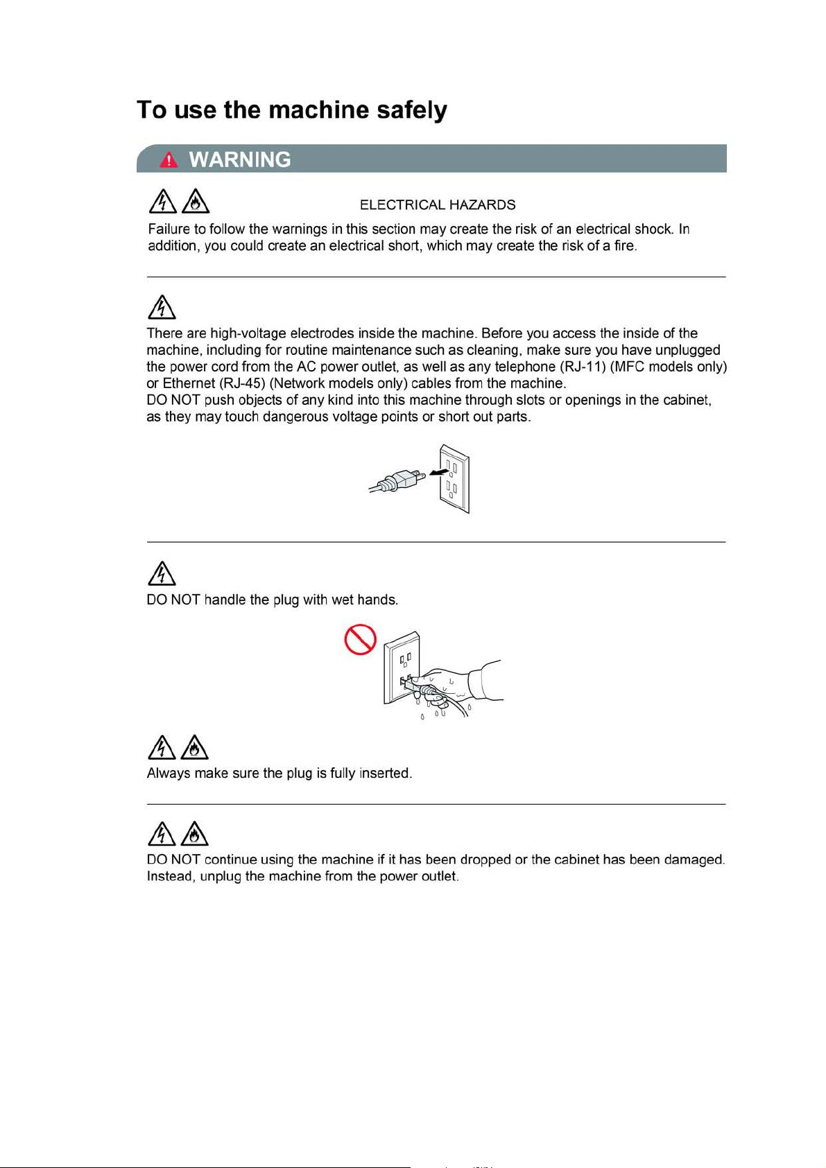
There are high-voltage electrodes inside the machine . Before you access the inside
machine, including for routine maintenance such
the power cord from the AC power outlet, as well as any telephone (RJ-11) (MFC models only)
or
Ethernet (RJ-45) (Network models only) cables from the machine.
DO NOT push objects
as they may touch dangerous voltage points
DO NOT handle the plug with wet hands.
of
in
this section may create the risk
as
cleaning, make sure you have unplugged
any kind into this machine through slots
or
short out parts.
of
an electrical shock . In
of
a fire.
or
openings
in
the cabinet,
of
the
Always make sure the plug is fully inserted .
if
DO NOT continue using the machine
Instead, unplug the machine from the power outlet.
it has been dropped
xv
or
the cabinet has been damaged.
Confidential
Page 19
If
water, other liquids, or metal objects get inside the machine, immediately unplug the machine
from the AC power outlet.
to
DO NOT connect the machine
of
power source you have, contact a qualified electrician.
Power Cord Safety:
• DO NOT pull on the middle
to separate from the plug. Doing this might cause
• DO NOT allow anything to rest
• DO NOT place this machine where people can walk on the cord.
• DO NOT place this machine
become worn
• DO NOT use the machine or handle the cord if the cord has become worn or frayed.
unplugging your machine, DO NOT touch the damaged/frayed part.
•Brother
DO NOT use this product during an electrical storm .
or
frayed.
strongly recommends that you DO NOT use any type
a DC power source
of
the
AC
power cord; pulling on the middle may cause the cord
on
the power cord.
in
a position where the cord is stretched
or
inverter.
an
electrical shock.
If
you are not sure what kind
or
strained, as it may
of
extension cord.
If
(MFC models only)
Never touch telephone wires
been unplugged at the wall jack. Never install telephone wiring during a lightning storm. Never
install a telephone wall jack
FIRE HAZARDS
Failure to follow the warnings
DO NOT use flammable substances, any type
alcohol
of fire or electrical shock.
or
ammonia to clean the inside or outside
or
terminals that are
in
a wet location.
in
this section may create the risk
not
of
spray
of
the machine. Doing this may cause a risk
insulated unless the telephone line has
of
a fire.
or
an organic solvent/liquid that contains
&
DO NOT use this machine in the vicinity
For users with pacemakers
This machine generates a weak magnetic field.
your pacemakers when near the machine, move away from the machine and consult a doctor
immediately.
of
combustible dust.
If
you feel anything wrong with the operation
of
xvi
Confidential
Page 20
A CAUTION
DO NOT sit or stand on the machine or use it for any purpose beyond its intended purpose.
If
the machine becomes hot, releases smoke,
unplug the machine from the AC power outlet.
Wait until pages have exited the machine before picking them up. Doing this may cause injury
to your fingers by trapping them in a roller.
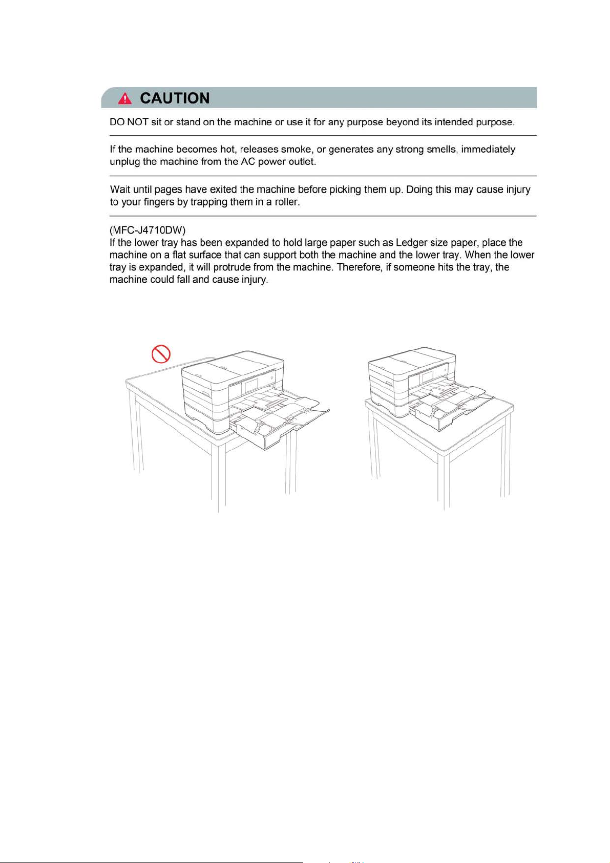
(MFC-J4710DW)
If
the lower tray has been expanded to hold large paper such as Ledger size paper, place the
machine on a flat surface that can support both the machine and the lower tray. When the lower
tray is expanded, it will protrude from the machine. Therefore, if someone hits the tray , the
machine could fall and cause injury .
or
generates any strong smells, immediately
xvii
Confidential
Page 21
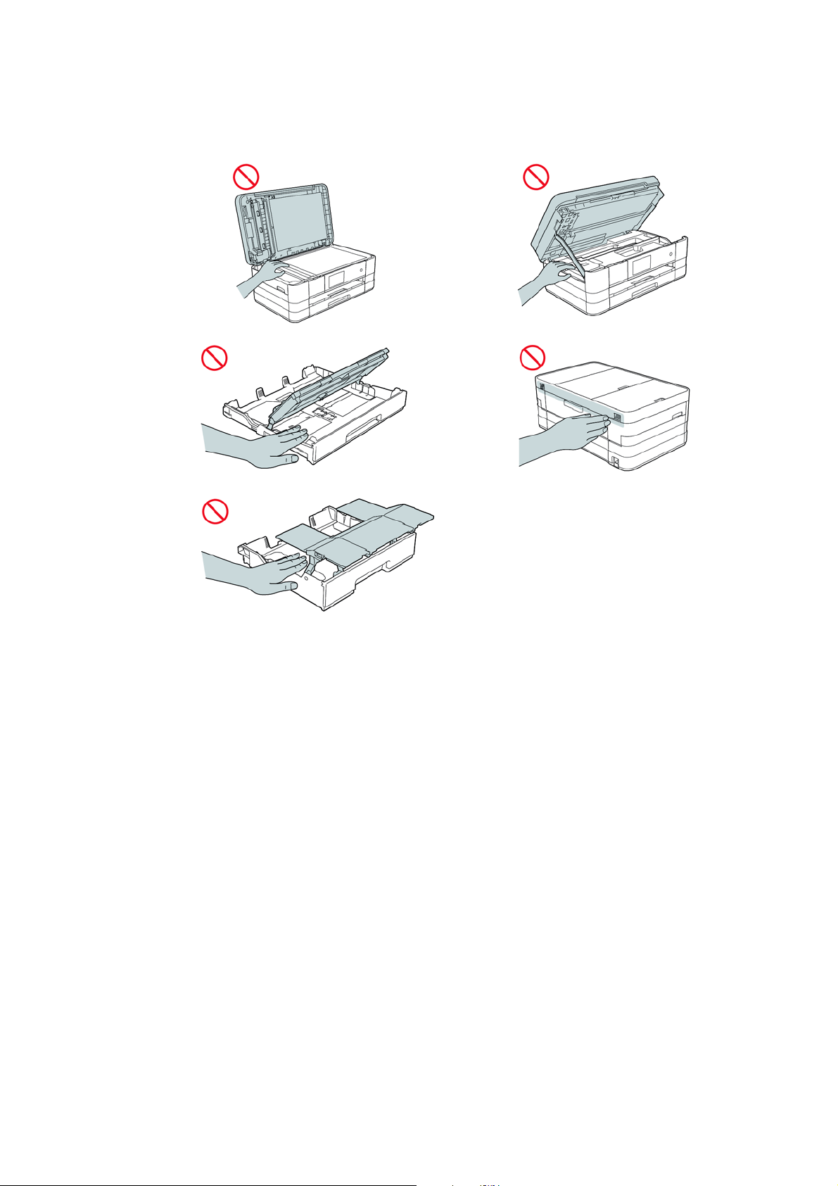
DO NOT put your hands on the edge of the machine. Doing this may cause injury to your
fingers by pinching them.
xviii
Confidential
Page 22
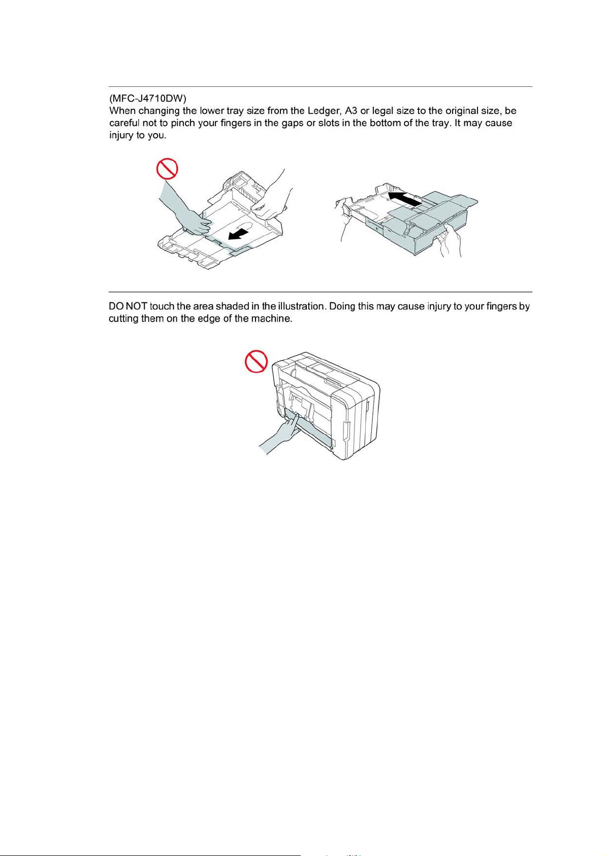
(MFC-J4710DW)
When changing the lower tray size from the Ledger, A3 or legal size to the original size, be
careful not to pinch your fingers
in
the gaps or slots in the bottom
of
the tray. It may cause
injury to you.
DO NOT touch the area shaded in the illustration. Doi
cutting them on the edge
of
the machine.
ng
this may cause injury to your fingers
by
xix
Confidential
Page 23
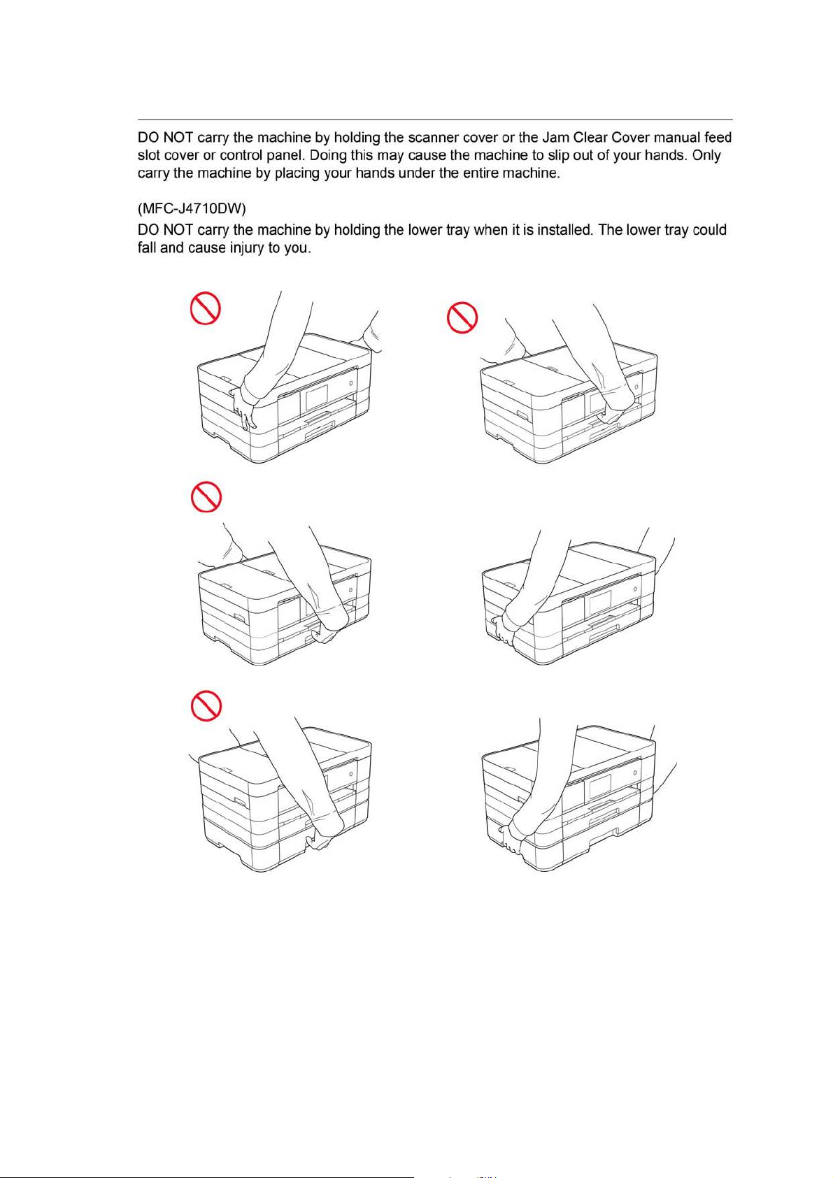
DO
NOT
carry
the
slot cover or control
carry the machine
(MFC-J4710DW)
DO
NOT
carry
the
fall
and
cause
injury to
machine
panel. Doi
by
placi
machine
you
by
holding
ng
ng
your hands under
by
holding
this
the
may
the
.
scanner cover or
cause
the
machine
the
entire machine.
lower tray
when
the
Jam
to
slip out of your
it
is
installed.
Clear Cover
The
lower tray
manual
hands.
feed
Only
could
xx
Confidential
Page 24
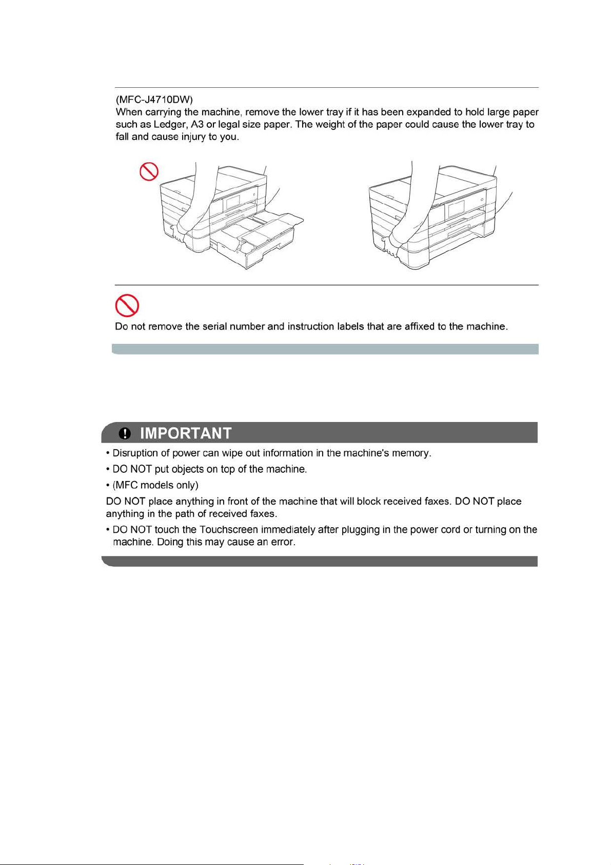
(MFC-J4710DW)
When carrying the machine, remove the lower tray if it has been expanded to hold large paper
such as Ledger, A3
fall and cause injury to you.
Do not remove the serial number and instruction labels that are affixed to the machine.
or
legal size paper. The weight
of
the paper could cause the lower tray to
! IMPORTANT
•D
isruption
• DO NOT put objects on top
• (MFC mode ls only)
DO
NOT place anything in front
anything in the path
•DO
machine. Doing this may cause an error.
of
power can wipe out information in the machine's memory.
of
the machine.
of
the machine that wi
of
received faxes.
NOT touch the Touchscreen immediately after plugging in the power cord
ll
block received faxes. DO
NOT
place
or
turning on the
xxi
Confidential
Page 25
CHAPTER 1 SPECIFICATIONS
This chapter lists the specifications of each model, which enables you to make a comparison of
different models.
1GENERAL
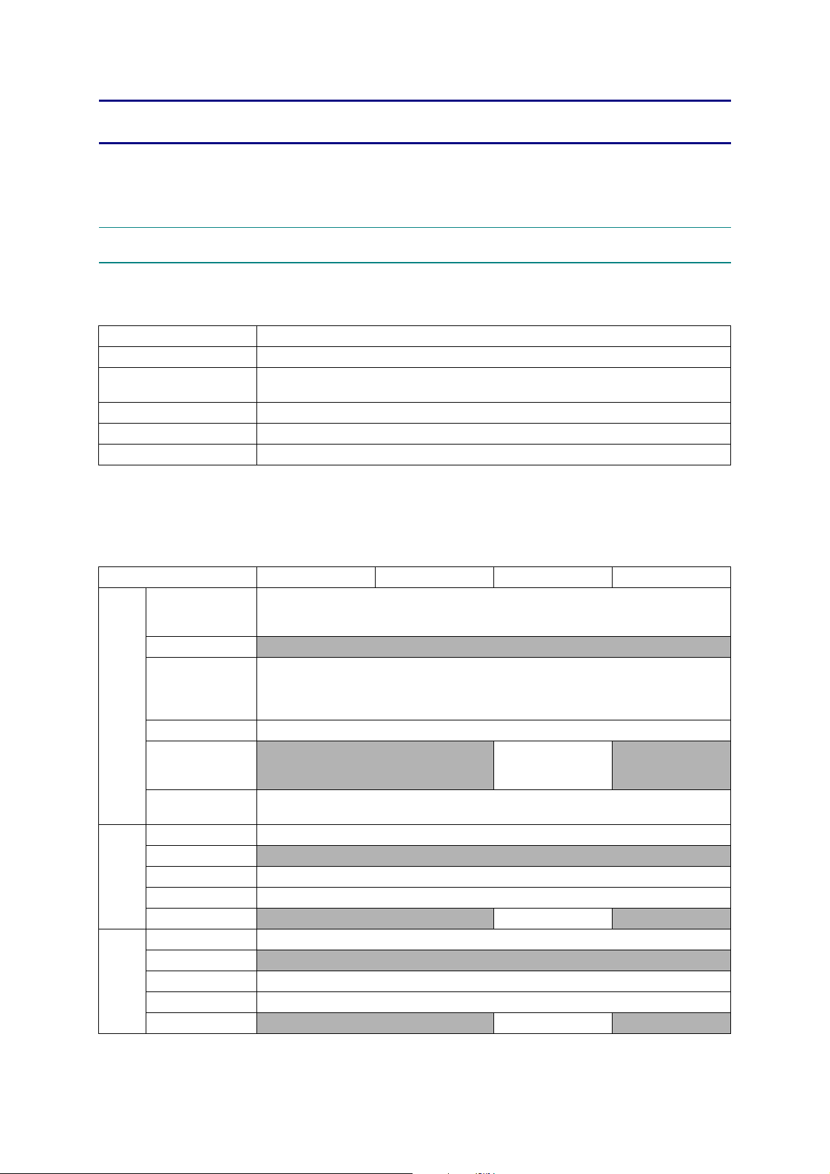
1.1 General
Model ALL models
Print Head BH13 BK/C/M/Y: 420/420/420/420 nozzles
Minimum Droplet Size
Scanning Method CIS
CPU Speed 288 MHz
Backup Clock Yes (Up to 1 hour)
BK: 3 pl
CMY: 1.5 pl
1.2 Media Specification
Model DCP-J4110DW MFC-J2310 MFC-J2510 MFC-J4310DW
Standard Tray
Lower Tray
Media
Sizes
Media
Weights
Media
Types
*1
*2
Manual Feed Slot
Duplex Print <PC Print>A4/LTR/EXE/A5,<Copy>LTR/A4/A5/EXE *
ADF (width/length)
Scanner Glass
(width/length)
Standard Tray 64-220 g/m
Lower Tray N/A
Manual Feed Slot 64-220 g/m
Duplex Print 64-105 g/m
ADF N/A 64-90 g/m
Standard Tray Plain, Inkjet, Glossy (cast/resin), Transparency
Lower Tray
Manual Feed Slot Plain, Inkjet, Glossy (cast/resin), Transparency
Duplex Print Plain
ADF
MFC-J2510 For CHN
MFC-J2510 For CHN, HK, TW and KOR
<Landscape>A4, LTR, EXE, B5
*1
Indexcard (127 x 203 mm/5 x 8"), Photo-L (89 x 127 mm/3.5 x 5"),
Photo-2L (127 x 178 mm/5 x 7"), Com-10, DL Envelope, Monarch
<Landscape>A4, LTR, EXE, B5
<Portrait>A3, LGR, LGL, A5, A6, Photo (102 x 152 mm/4 x 6"),
Indexcard (127 x 203 mm/5 x 8"), Photo-L (89 x 127 mm/3.5 x 5"),
Photo-2L (127 x 178 mm/5 x 7"), C5, Com-10, DL Envelope, Monarch
N/A
Up to 215.9/297 mm (up to 8.5/11.7")
N/A Plain N/A
<Portrait>A5, A6, Photo (102 x 152 mm/4 x 6"),
N/A
*2
*2
, B4
148/148 mm to 215.9/
355.6 mm
(5.8/5.8" to 8.5/14.0")
2
(17-58 lb. )
2
(17-58 lb. )
2
(17-28 lb. )
2
(17-24 lb. ) N/A
N/A
N/A
1-1
Confidential
Page 26
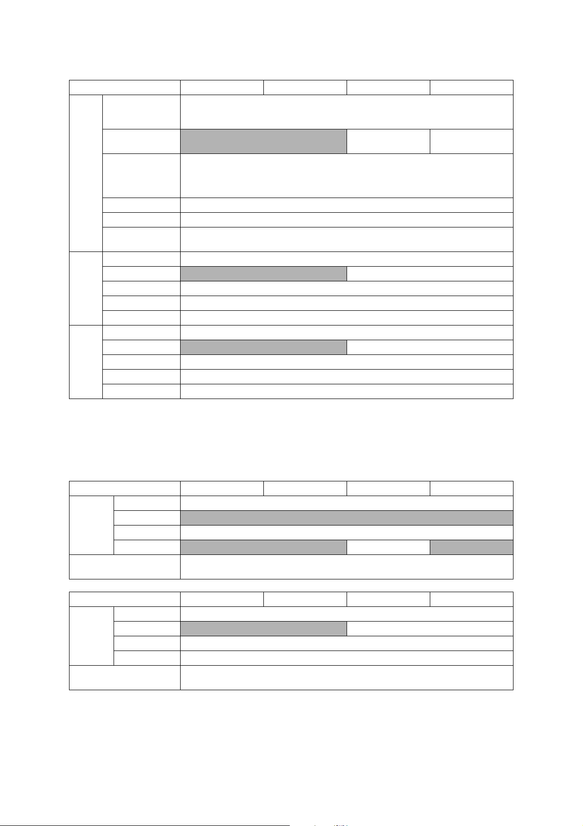
Standard Tray
Lower Tray
Media
Sizes
Manual Feed Slot
Duplex Print <PC Print>A4/LTR/EXE/A5,<Copy>LTR/A4/A5/EXE *
ADF(width/length) 148/148 mm to 215.9/355.6 mm (5.8/5.8" to 8.5/14.0")
Scanner Glass
(width/length)
Standard Tray 64-220 g/m
Lower Tray N/A 64-105 g/m
Media
Weights
Manual Feed Slot 64-220 g/m
Duplex Print 64-105 g/m
ADF 64-90 g/m
Standard Tray Plain, Inkjet, Glossy (cast/resin), Transparency
Lower Tray
Media
Types
Manual Feed Slot Plain, Inkjet, Glossy (cast/resin), Transparency
Duplex Print Plain
ADF Plain
* For US only
Model MFC-J4410DW MFC-J4510DW MFC-J4610DW MFC-J4710DW
<Landscape>A4, LTR, EXE<Portrait>A5, A6, Photo (102 x 152 mm/4 x 6"),
Indexcard (127 x 203 mm/5 x 8"), Photo-L (89 x 127 mm/3.5 x 5"),
Photo-2L (127 x 178 mm/5 x 7"), Com-10, DL Envelope, Monarch
N/A A4, LTR
A3, LGR, A4, LTR,
LGL
<Landscape>A4, LTR, EXE,
<Portrait>A3, LGR, LGL, A5, A6, Photo (102 x 152 mm/4 x 6"),
Indexcard (127 x 203 mm/5 x 8"), Photo-L (89 x 127 mm/3.5 x 5"),
Photo-2L (127 x 178 mm/5 x 7"), C5, Com-10, DL Envelope, Monarch
Up to 215.9/297 mm (up to 8.5/11.7")
2
(17-58 lb. )
2
(17-28 lb. )
2
(17-58 lb. )
2
(17-28 lb. )
2
(17-24 lb. )
N/A Plain
1.3 Paper Handling
Model DCP-J4110DW MFC-J2310 MFC-J2510 MFC-J4310DW
Standard Tray 150 (80 g/m
Paper Input
(sheets)
Output Paper Capacity
(sheets)
Paper Input
(sheets)
Output Paper Capacity
(sheets)
Lower Tray N/A
Manual Feed Slot 1
ADF
Model MFC-J4410DW MFC-J4510DW MFC-J4610DW MFC-J4710DW
Standard Tray 150 (80 g/m
Lower Tray N/A 250 (80 g/m
Manual Feed Slot 1
ADF 20 (80 g/m
2
)
N/A 20 (80 g/m2) N/A
50 (80 g/m
50 (80 g/m
2
)
2
)
2
)
2
)
2
)
1-2
Confidential
Page 27
1.4 LCD Panel
Model DCP-J4110DW MFC-J2310 MFC-J2510 MFC-J4310DW
Type & Size 1.8 inch TFT 3.7 inch TFT 1.8 inch TFT
LCD
Touch-Panel Yes
Model MFC-J4410DW MFC-J4510DW MFC-J4610DW MFC-J4710DW
Type & Size 1.8 inch TFT 3.7 inch TFT 1.8 inch TFT 3.7 inch TFT
LCD
Touch-Panel Yes
1.5 Memory
Model DCP-J4110DW MFC-J2310 MFC-J2510 MFC-J4310DW
Memory Capacity
(physical: Mbytes)
Memory Backup
(with Flash memory)
Model MFC-J4410DW MFC-J4510DW MFC-J4610DW MFC-J4710DW
Memory Capacity
(physical: Mbytes)
Memory Backup
(with Flash memory)
128 MB
N/A Yes
128 MB 256 MB
Ye s
1.6 Interface
Model All models
Host Interface Hi-Speed USB 2.0
LAN Ye s
Wireless LAN Yes
PictBridge Yes
USB Memory up to 32 GB
Memory Stick Duo: 16 MB-128 MB
Memory Stick Pro Duo: 256 MB-32 GB (MagicGate: YES if not use MG function)
Memory Stick Micro: 256 MB-32 GB (MagicGate: YES if not use MG function)
Acceptable Media Cards
(Type & Size)/Media Card
SD Memory Card: 16 MB-2 GB (miniSD, miroSD with Adapter)
SDHC Memory Card: 4 GB-32 GB (miniSDHC, miroSDHC with Adapter)
SDXC Memory Card: 48 GB-128 GB
MultiMedia Card: 32 MB-2 GB
MultiMedia Card plus: 128 MB-4 GB
MultiMedia Card mobile: 64 MB-1 GB (with Adapter)
1-3
Confidential
Page 28

1.7 Others
Model DCP-J4110DW MFC-J2310 MFC-J2510 MFC-J4310DW
Operating Environment
Temperature
(Best Print Quality)
Operating Environment
Humidity
(Best Print Quality)
Power
Consumption
(Operating/
Standby/Sleep
mode/Off)
Machine Noise (Operating)
Machine Dimensions W480 x D290 x H163 mm
Machine Weight 8 kg (17.6 lb) 9.3 kg (20.5 lb) 8 kg (17.6 lb)
Operating Environment
Temperature
(Best Print Quality)
Operating Environment
Humidity
(Best Print Quality)
Power
Consumption
(Operating/
Standby/Sleep
mode/Off)
Machine Noise
Machine Dimensions W480 x D290 x H186 mm W480 x D290 x H254 mm
Machine Weight 9.2 kg (20.3 lb) 9.3 kg (20.5 lb)
U.S.A
Europe
Asia/Oceania 21/6/1.5/0.04W
China
Model MFC-J4410DW MFC-J4510DW MFC-J4610DW MFC-J4710DW
U.S.A 21/5/1.5/0.04W 23/5/1.5/0.04W
Europe
Asia/Oceania
China N/A
21/5.5/1/0.04W
N/A N/A
21/6/1.5/0.04W 21/5.5/1.5/0.04W
10-35 (20-33) degrees centigrade
20-80 (20-80) %
N/A 21/5/1.5/0.04W
21/6/1.5/0.04W 21/5.5/1.5/0.04W
50 dBA (Average)
W480 x D290 x
H186 mm
10-35 (20-33) degrees centigrade
20-80 (20-80) %
21/6/1.5/0.04W
N/A
50 dBA (Average)
For US 11 kg (24.3 lb)
For EU 10.8 kg (23.8 lb)
W480 x D290 x
21/5.5/1.5/0.04W
For US 11.5 kg (25.4 lb)
For EU/AP 11.3 kg
N/A
H163 mm
(24.9 lb)
1-4
Confidential
Page 29
2FAX
Model DCP-J4110DW MFC-J2310 MFC-J2510 MFC-J4310DW
Modem Speed (bps)
Transmission Speed
ITU-T Group
Document
COLOR FAX
Modem Speed (bps)
Transmission Speed
ITU-T Group
COLOR FAX
(Send/Receive)
Memory
(Send/Receive)
Model MFC-J4410DW MFC-J4510DW MFC-J4610DW MFC-J4710DW
Document
(Send/Receive)
Memory
(Send/Receive)
N/A 33,600 (FAX)
N/A Approx.3sec (ITU-T Test Chart #1, MMR)
N/A Super G3
N/A Yes/Yes (ITU-T color FAX)
N/A No/No (ITU-T color FAX)
33,600 (FAX)
Approx.3sec (ITU-T Test Chart #1, MMR)
Super G3
Yes /Ye s (I T U -T c olor FA X )
No/No (ITU-T color FAX)
3 PRINTER
Model DCP-J4110DW MFC-J2310 MFC-J2510 MFC-J4310DW
Print Speed ESAT
(mono/color)
(based on ISO/IEC 24734)
Draft Print Speed
(mono/color)
*time calculated including
paper feeding
Resolution
(horizontal x vertical)
Auto Duplex Print Yes (up to A4/LTR)
Model MFC-J4410DW MFC-J4510DW MFC-J4610DW MFC-J4710DW
Print Speed ESAT
(mono/color)
(based on ISO/IEC 24734)
Draft Print Speed
(mono/color)
*time calculated including
paper feeding
Resolution
(horizontal x vertical)
Auto Duplex Print Yes (up to A4/LTR)
18/16 ipm 20/18 ipm
33/25 ppm 35/27 ppm
18/16 ipm 20/18 ipm 18/16 ipm
33/25 ppm
Up to 1,200 x 6,000 dpi
Up to 1,200 x 6,000 dpi
1-5
Confidential
Page 30

4COPY
Model DCP-J4110DW MFC-J2310 MFC-J2510 MFC-J4310DW
COPY SPEED ESAT
(based on ISO/IEC 24735)
(mono/color)
*This spec is for ADF model only.
COPY SPEED sESAT
(based on ISO/IEC 29183)
*
This spec is for non-ADF model only.
COPY SPEED FCOT
(based on ISO/IEC 24735
Annex D)
Resolution
(horizontal x
vertical)
Auto Duplex Print Yes
COPY SPEED ESAT
(based on ISO/IEC 24735)
(mono/color)
*This spec is for ADF model only.
COPY SPEED sESAT
(based on ISO/IEC 29183)
*
This spec is for non-ADF model only.
COPY SPEED FCOT
(based on ISO/IEC 24735
Annex D)
Resolution
(horizontal x
vertical)
Auto Duplex Print Yes
Mono
Color
Model MFC-J4410DW MFC-J4510DW MFC-J4610DW MFC-J4710DW
Mono
Color
N/A 12/9 ipm N/A
15/10 ipm N/A
18 sec
Print: Max. 1,200 x 1,200 dpi
Scan: Max. 1,200 x 1,200 dpi
Print: Max. 1,200 x 1,200 dpi
Scan: Max. 1,200 x 1,200 dpi
12/9 ipm
N/A
18 sec
Print: Max. 1,200 x 1,200 dpi
Scan: Max. 1,200 x 1,200 dpi
Print: Max. 1,200 x 1,200 dpi
Scan: Max. 1,200 x 1,200 dpi
1-6
Confidential
Page 31

5 SCANNER
Model DCP-J4110DW MFC-J2310 MFC-J2510 MFC-J4310DW
Scan speed
(Mono/Color) *@100 dpi
Scan speed (Duplex)
(Mono/Color) *@100 dpi
Resolution
(horizontal x
vertical)
Scan speed
(Mono/Color) *@100 dpi
Scan speed (Duplex)
(Mono/Color) *@100 dpi
Resolution
(horizontal x
vertical)
Optical FB: 2,400 x 2,400 dpi
Interpolated For XP/Vista/Windows 7, up to 19,200 x 19,200 dpi with Scanner Utility
Model MFC-J4410DW MFC-J4510DW MFC-J4610DW MFC-J4710DW
Optical
Interpolated For XP/Vista/Windows 7, up to 19,200 x 19,200 dpi with Scanner Utility
A4: 3.37 sec/3.37 sec
LTR: 3.17 sec/3.17 sec
N/A
FB: 2,400 x 2,400 dpi
ADF: 2,400 x 1,200 dpi
A4: 3.37 sec/3.37 sec
LTR: 3.17 sec/3.17 sec
N/A
FB: 2,400 x 2,400 dpi
ADF: 2,400 x 1,200 dpi
FB: 2,400 x 2,400 dpi
A4: 3.37 sec/13.37 sec
LTR: 3.17 sec/13.17 sec
6 SOFTWARE
Model All models
Driver Support
OS Version
Windows
Macintosh Mac OS X v10.5.8/10.6.x/10.7.x
Windows XP/XP x64/Vista/7
Windows Server 2003/2008
1-7
Confidential
Page 32

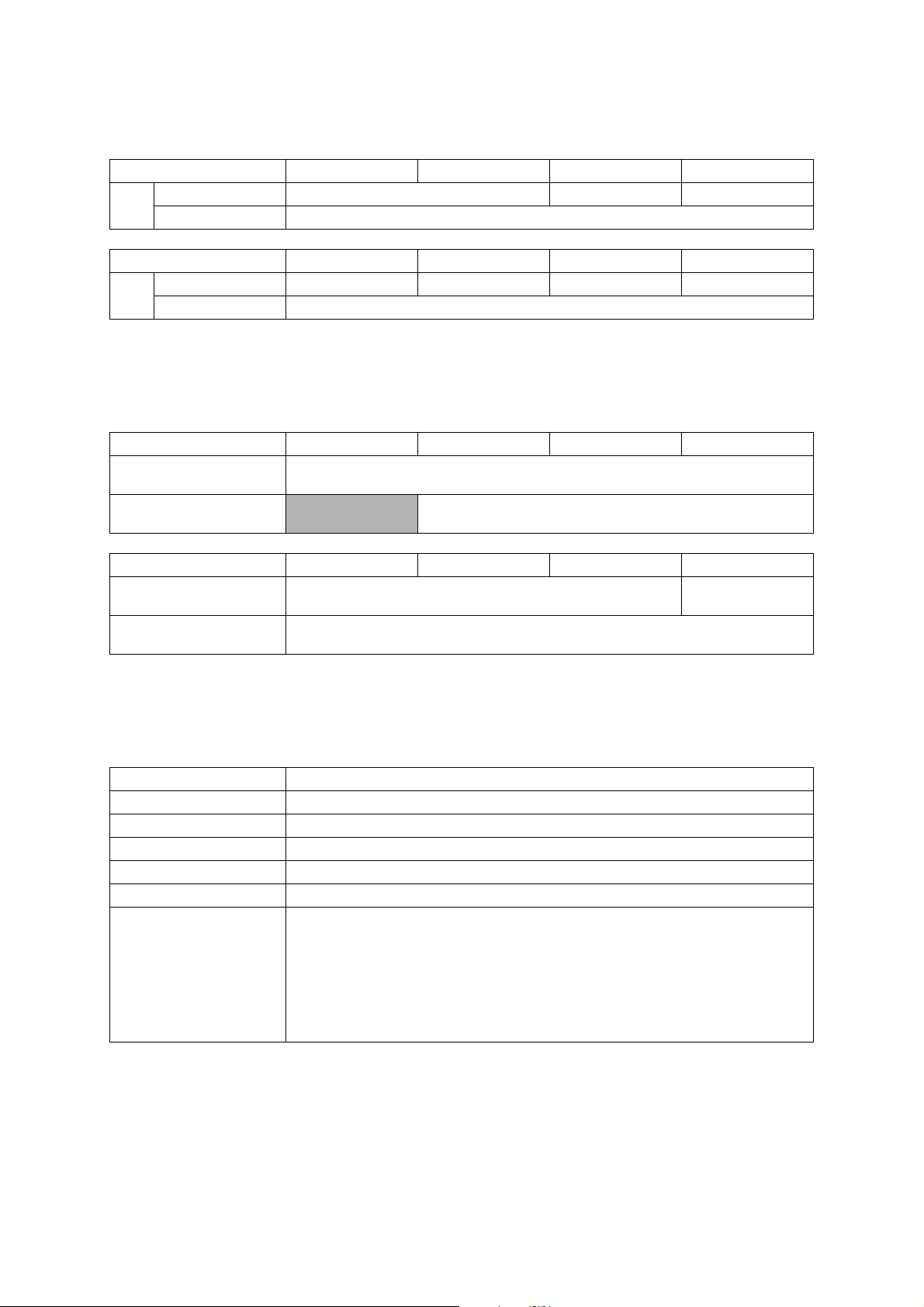
7NETWORK
7.1 Network
Model DCP-J4110DW MFC-J2310 MFC-J2510 MFC-J4310DW
Internet FAX (Firmware)
(versionT37)
Model MFC-J4410DW MFC-J4510DW MFC-J4610DW MFC-J4710DW
Internet FAX (Firmware)
(versionT37)
7.2 Wired
Model All models
Model Name (Ethernet) Embedded (NC-280h)
Network Connection (Ethernet) Ethernet 10/100BASE-TX Auto Negotiation
N/A Yes (Download)
Yes (Download)
7.3 Wireless
Model All models
Model Name (Wireless) Embedded (NC-290w)
Network Connection
(Wireless)
Wireless Security
AOSS Yes
Setup Support
Utility
WPS (Wifi
Protected
Setup)
SSID (32 chr), WEP 64/128 bit, WPA-PSK (TKIP/AES),
IEEE802.11 b/g/n
WPA2-PSK (AES) **NO LEAP**
Ye s
1-8
Confidential
Page 33

8 SUPPLIES/OPTIONS
Model All models
Ink
Cartridge
Yield @
ISO/IEC
pattern
Storage Condition of Ink
Cartridge
Bundled Cartridges
Supply High Yield
Cartridges
Supply Super High
Yield Cartridges
*Storage condition at the temperature of 40 to 50°C and the humidity of 80 to 95% :
*Storage condition at the temperature of 40 to 60°C and the humidity of Non controll condition :
9 SERVICE INFORMATION
BK: 390
CL: 390
BK: 600
CL: 600
BK: 1,200
CL: 1,200
(Temperature) Normal condition : -20 to 40°C
(Humidity) Normal condition : 20 to 80%
Up to 5 days
Up to 5 days
Model All models
Monthly Volume 13,000 pages
Machine Life 50,000 pages or 5 years
MTBF (Mean Time Between
Failures)
MTTR (Mean Time To Be
Repaired)
4,000 hours
30 minutes
1-9
Confidential
Page 34

10 PAPER
10.1 Paper
Paper type and size for each operation
Paper Type Paper Size Usage
Fax Copy Photo
Capture
Cut-Sheet Ledger 11 x 17 in. (279.4 x 431.8 mm) Yes
*2
Letter 8 1/2 x 11 in. (215.9 x 279.4 mm) Yes Yes Yes Yes
A3 11.7 x 16.5 in. (297 x 420 mm) Yes
*2
A4 8.3 x 11.7 in. (210 x 297 mm) Yes Yes Yes Yes
Legal 8 1/2 x 14 in. (215.9 x 355.6 mm) Yes*2Yes
Executive 7 1/4 x 10 1/2 in. (184 x 267 mm) -- Yes -- Yes
JIS B4 10.1 x 14.3 in. (257 x 364 mm) -- -- -- User
JIS B5 7.2 x 10.1 in. (182 x 257 mm) -- -- -- User
A5 5.8 x 8.3 in. (148 x 210 mm) -- Yes -- Yes
A6 4.1x 5.8 in. (105 x 148 mm) -- -- -- Yes
Cards Photo 4 x 6 in. (10 x 15 cm) -- Yes Yes Yes
Photo L 3 1/2 x 5 in. (89 x 127 mm) -- -- -- Yes
Photo 2L 5 x 7 in. (13 x 18 cm) -- -- Yes Yes
Index Card 5 x 8 in. (127 x 203 mm) -- -- -- Yes
Postcard 1 3.9 x 5.8 in. (100 x 148 mm) -- -- -- User
Postcard 2
5.8 x 7.9 in. (148 x 200 mm) -- -- -- User
(Double)
Envelopes C5 Envelope 6.4 x 9 in. (162 x 229 mm) -- -- -- Yes
DL Envelope 4.3 x 8.7 in. (110 x 220 mm) -- -- -- Yes
COM-10 4 1/8 x 9 1/2 in. (105 x 241 mm) -- -- -- Yes
Monarch 3 7/8 x 7 1/2 in. (98 x 191 mm) -- -- -- Yes
Y4 Envelope 4.1 x 9.3 in. (105 x 235 mm) -- -- -- User
Transparencies Letter 8 1/2 x 11 in. (215.9 x 279.4 mm) -- Yes -- Yes
A4 8.3 x 11.7 in. (210 x 297 mm) -- Yes -- Yes
Legal 8 1/2 x 14 in. (215.9 x 355.6 mm) -- Yes -- Yes
A5 5.8 x 8.3 in. (148 x 210 mm) -- Yes -- Yes
*1
Manual Feed Slot only (MFC-J4510DW)
Manual Feed Slot or Tray #2 (MFC-J4710DW)
*2
Lower Tray only (MFC-J4710DW)
*3
Manual Feed Slot only
Yes
Yes
*1
Yes
*1
Yes
*1
-- Yes
*3
*3
Printer
*1
Yes
*1
Yes
*1
Defined
Defined
Defined
Defined
*1
*1
*1
*1
Defined
1-10
Confidential
Page 35

Paper weight and thickness
Paper Type Weight Thickness
2
Cut-Sheet Plain Paper 17 to 32 lb (64 to 120 g/m
(Lower Tray)
17 to 28 lb (64 to 105 g/m
) 3 to 6 mil (0.08 to 0.15 mm)
2
) 3 to 6 mil (0.08 to 0.15 mm)
Plain Paper
Inkjet Paper 17 to 53 lb (64 to 200 g/m2) 3 to 10 mil (0.08 to 0.25 mm)
Glossy Paper
Cards Photo 4"x 6" Card
*1
Up to 58 lb (Up to 220 g/m2) Up to 10 mil (Up to 0.25 mm)
*1
Up to 58 lb (Up to 220 g/m2) Up to 10 mil (Up to 0.25 mm)
Index Card Up to 32 lb (Up to 120 g/m2) Up to 6 mil (Up to 0.15 mm)
Postcard 1
Up to 53 lb (Up to 200 g/m
2
) Up to 10 mil (Up to 0.25 mm)
Postcard 2
Envelopes 20 to 25 lb (80 to 95 g/m2) Up to 20 mil (Up to 0.52 mm)
Transparencies -- --
*1
BP71 69 lb (260 g/m2) paper is especially designed for Brother inkjet machines.
Paper capacity of the paper trays
Paper size Paper types
Standard Tray <Landscape>Letter,
Executive, A4
<Portrait>
A5, A6, Photo, Photo L,
Photo 2L, Index card,
Envelopes (Com-10, DL,
Monarch)
Lower Tray
(MFC-J4610DW/J4710DW)
<Landscape>Letter, A4
<Portrait>Ledger, A3, Legal
Manual Feed Slot <Landscape>Letter,
Executive, A4
<Portrait>
Ledger, A3, Legal, A5, A6,
Photo, Photo L, Photo 2L,
Index card, Envelopes (C5,
Com-10, DL, Monarch)
*1
Up to 250 sheets of plain paper 20 lb (80 g/m2).
Plain Paper 150
Inkjet Paper 20
Glossy Paper, Photo 20
Index Card, Postcard 30
Envelopes, Transparencies 10
Plain Paper 250
Plain Paper, Inkjet Paper,
Glossy Paper, Envelopes and
Transparencies
*1
*1
1
Recommended print media
To get the best print quality, we suggest using Brother paper. (See the table below.)
If Brother paper is not available in your country, we recommend testing various papers before
purchasing large quantities.
We recommend using "3M Transparency Film" when you print on transparencies
Brother paper
Paper Type Item
Premium Plus Glossy Photo
- Ledger BP71GLGR
- Letter BP71GLTR
- 4" x 6" BP71GP
Plain Inkjet
- Ledger BP60PLGR (USA only)
1-11
.
Confidential
Page 36

Handling and using print media
Store paper in its original packaging and keep it sealed. Keep the paper flat and away from
moisture, direct sunlight and heat.
Avoid touching the shiny (coated) side of photo paper. Load photo paper with the shiny side
facing down.
Avoid touching either side of transparencies because they absorb water and perspiration
easily, and this may cause decreased output quality. Transparencies designed for laser
printers/copier may stain your next document. Use only transparencies recommended for
inkjet printing.
1-12
Confidential
Page 37

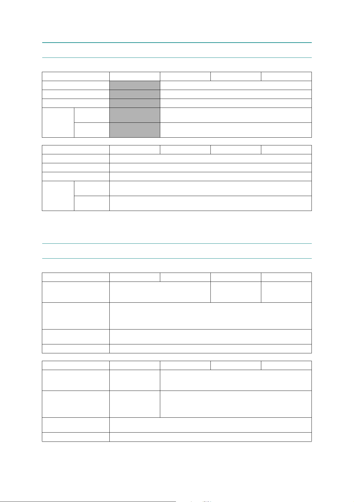
10.2 Printable Area
1
3
42
1
3
42
Cut-Sheet Paper Envelopes
The printable area depends on the settings in the application you are using. The figures below
show the unprintable areas on cut-sheet paper and envelopes. The machine can print in the
shaded areas of cut-sheet paper only when the Borderless print feature is available and turned
on.
Top (1) Left (2) Bottom (3) Right (4)
Cut-Sheet 0.12 in. (3 mm) 0.12 in. (3 mm) 0.12 in. (3 mm) 0.12 in. (3 mm)
Envelopes 0.87 in. (22 mm) 0.12 in. (3 mm) 0.87 in. (22 mm) 0.12 in. (3 mm)
1-13
Confidential
Page 38

CHAPTER 2 TROUBLESHOOTING
WARNING
1 INTRODUCTION
This section gives the service personnel some of the troubleshooting procedures to be followed
if an error or malfunction occurs with the machine. It is impossible to anticipate all of the
possible problems which may occur in future and determine the troubleshooting procedures, so
this section covers some sample problems. However, those samples will help service personnel
pinpoint and repair other defective elements if he/she analyzes and examines them well.
1.1 Precautions
Be sure to observe the following to prevent any secondary troubles from happening during
troubleshooting.
(1) AC power codes must be removed from their outlets before starting any removal of covers
and PCBs, adjustments and conductivity test using a tester.
(2) When disconnecting the connectors, hold the connector housings. Do not pull the lead
wires.
(3) Static electricity charged in your body may damage electronic parts.
Before handling the PCBs, touch a metal portion of the machine to discharge static
electricity charged in your body. When transporting PCBs, be sure to wrap them in
conductive sheets.
When replacing the PCBs, put on a grounding wrist band and perform the job on a
conductive mat.
Also take care not to touch the conductor sections on the flat cables.
(4) Be sure to observe the warnings.
WARNING
DO NOT use flammable substances such as alcohol, benzine, thinner or any type of spray to
clean the inside or outside of the machine. Doing this may cause a fire or electrical shock.
(5) After repairing the defective section, be sure to check again if the repaired section works
correctly.
2-1
Confidential
Page 39

1.2 Initial Check
Prior to proceeding to the troubleshooting procedures, make the following initial checks:
Environmental conditions
(1) The machine is placed on a flat, firm surface.
(2) The machine is used in clean environment with temperature (10 to 35 degree-C) and
humidity (20 to 80 %.)
(3) The machine is not exposed to direct sunlight, excessive heat, moisture, or dust.
(4) The machine is transported in level.
Power requirements
(1) The power requirements described in label of the machine is supplied. Its variation is
within +/-10% of the rated voltage.
(2) All cables and harnesses are firmly connected.
(3) The fuses are not blown.
Recording paper
(1) A recommended type of paper is being used (refer to Chapter 1, Section 10 "PAPER."
(2) The recording paper is not dampened.
Consumable Parts
(1) Ink cartridge (4 colors) is correctly set.
Head/carriage unit
(1) Repeat purge action (maintenance code 76) for a couple of times. (Refer to Chapter 5,
Section 1.3.29.)
Others
(1) Low temperature
Motor may not run correctly due to excessive load for each drive in low temperature
environment. Warm the room temperature in such case.
2-2
Confidential
Page 40

Cleaning
WARNING
Use a soft dry lint-free cloth.
WARNING
DO NOT use flammable solvent such as alcohol, benzine, thinner to clean the body of the
machine. DO NOT use near by.
2-3
Confidential
Page 41

2OVERVIEW
Document feed roller 2
Second side CIS
unit
Document scanning position actuator
Document separation roller
First side CIS unit
Document feed roller 1
ADF separation pad
Document detection actuator
Document pick-up roller
Document nip piece
Document pressure bar
2.1 Cross-section Drawings
2.1.1 Document scanning
2-4
Confidential
Page 42

2.1.2 Printer part
Switchback actuator
Paper ejection roller
Switchback roller
Control panel ASSY
Registration actuator
Manual feed slot
cover ASSY
Paper feed roller
Head/carriage unit
Duplex paper feed roller
Platen
T1 paper pull-in roller
paper tray 2
Bank ASSY
T2 paper pull-in roller
2-5
Confidential
Page 43

2.2 Document Feeding Path/Recording Paper Feeding Path
Document feeding path during ADF scanning
Feeding path during duplex-printing
Feeding path from the manual feed slot
Feeding path from paper tray 1
Feeding path from paper tray 2
2.2.1 Document Feeding Path
2.2.2 Recording Paper Feeding Path
2-6
Confidential
Page 44

2.3 Parts Names and Functions
Document scanning and feeding
Names Functions
Document detection actuator This detects whether documents are set on the document tray.
Document pick-up roller This pulls documents loaded in the document tray into the ADF.
Document separation roller,
ADF separation pad
Document feed roller 1 This feeds a document to the CIS unit.
Document scanning position
actuator
Document feed roller 2 This ejects the scanned document to ADF document support.
Printing and paper feeding
Names Functions
T1 paper pull-in roller This feeds recording paper from the paper tray 1.
T2 paper pull-in roller This feeds recording paper from the paper tray 2.
Registration actuator This detect the leading edge of recording paper, controlling the
Paper feed roller The leading edge of recording page hits the stopped paper feed
This separates documents sent by the document pick-up roller in
single sheet.
This detects the leading edge of document pages, indicating the
scanning start position.
This detects paper jamming in the ADF.
printing start position.
This detect the leading edge/ending edge of recording paper,
identifying the recording paper size.
This detects paper jamming in the rear.
roller, correcting inclination of the paper. After the correction, the
paper feed roller rotates, feeding the paper to printing start position.
Paper ejection roller This feeds printed recording paper to the switchback roller.
Switchback actuator This detects whether the printed recording papers are ejected.
This detects the ending edge of recording paper after printing the
first side when duplex-printing, adjusting timing to reverse the
switchback roller rotation.
This detect the leading edge/ending edge of recording paper when
duplex-printing, identifying the recording paper size.
This detects whether the recording papers are fed from the
switchback roller to the duplex-printing path.
This detects paper jamming in the ejector.
Detect if paper tray 1 is set.
Switchback roller This ejects the recording paper to the ejected paper tray.
During duplex-printing, after feeding some of the recording papers
printed in the first side to the switchback roller, its rotation is
reversed to feed the recording paper to the duplex-printing path.
Duplex paper feed roller During duplex-printing, this feeds the recording paper that are fed in
the duplex paper path to the paper feed roller.
2-7
Confidential
Page 45

2.4 Block Diagram
Modem PCB
EEPROM
DDR3
ROM
Front Ink Cover Switch
Carriage Unit
Print Engine
INK Refill Unit
ADF Unit
Scanner Unit
Main PCB
Speaker
CR Motor
AC line
Tel line
Ext Tel line
Backup
ROM
MS MSduoSD
USB
SDIO
SPI
LVDS
Power Supply
USB
ASIC
(Saffron)
USB
Host
LAN
(PHY)
LAN
(MAC)
PC
W-LAN
DX:A4 1200,3ch
PF Motor
Ink Cartridge PCB
Ink Empty Sensor PCB
Certification Chip PCB
RMII
AMP
Ethernet
Panel PCB
Panel Unit
Color
LCD
3.7/1.8”
Touch
Panel
LCD PCB
Document Cover Sensor*1
Scanner
Motor
Cartridge Sensor
Thermistor
AFE/ AFE/
LED Driver LED Driver
ADF
Motor
Ink Absorber Full Sensor
Power
Switch
*1 Duplex Model
Sensor Relay PCB
SDAAModem
Print Head Unit
Carriage PCB
CR Encoder Sensor
Head Thermistor
PF EncoderPCB
Registration Sensor PCB
Registration Sensor
Purge Cam Sensor
Switch Back Sensor
Document Detection Sensor PCB
Document Scanning Position Sensor PCB
A4 CIS A4 CIS
Document Scanner Sensor
Paper width Sensor
2-8
Confidential
Page 46

2.5 Components
ADF unit
Scanner cover damper
Scanner cover support
Harness cover
Upper side cover L
Engine unit
Registration sensor
PCB ASSY
Sensor relay PCB ASSY
Ink absorber box
Switchback
frame ASSY
Document scanner unit
Upper cover
Upper side cover R
Main PCB ASSY
Wireless LAN PCB ASSY
MJ PCB ASSY
Main PCB frame
Speaker spring
Speaker
Head/carriage unit
Maintenance unit
Ink refill ASSY
Jam clear cover
Flushing box
PF encoder
PCB ASSY
PF encoder
harness
Lower side cover L
Lower power
supply frame
Power supply PCB ASSY
Frame base
Lower cover
Front cover
2-9
Paper tray ASSY
Lower side cover R
Ink cartridge cover
sensor ASSY
Control panel ASSY
Inner media module cover
Media module cover
(BHS13_COMPONENTS_1_E)
Ink cartridge
cover
Confidential
Page 47

3 ERROR INDICATION
To help the user or the service personnel promptly locate the cause of a problem (if any), the
machine incorporates the self-diagnostic functions which display error messages for equipment
errors.
3.1 Error Code
Error
Code
0D
0E
13
15
17
18
Contents
Paper jam during duplex-printing
The recording papers are fed in reverse on the platen when switchback drive is
started, triggering switchback sensor as paper feeding condition.
Defective during duplex-printing
Switchback sensor detects paper feed condition at out of specified timing
during switchback.
Defective during duplex-printing
Registration sensor detects paper feed condition at out of specified timing
during switchback.
Paper jam during duplex ejecting
Recording paper is not able to be ejected since it is longer than 840 mm when
ejecting the paper.
Recording paper size error (duplex-printing/duplex-copying)
-Paper width is wider than 301.5 mm (detection by media sensor)
-Paper width is narrower than 95.5 mm (detection by media sensor)
-Paper length is longer than 245.9 mm (detection by registration, SB sensor)
-Paper length is shorter than 143.5 mm (detection by registration, SB sensor)
Paper jam during duplex-printing
Registration sensor does not detect paper feed within specified pulse numbers
in the second side paper re-feed.
Refer to
page:
2-21
2-21
2-22
2-22
2-23
2-24
20
21
22
23
24
25 Cannot communicate with ink cartridge IC chip (ink cartridge side.) 2-26
Cannot identify a black ink cartridge.
The ink cartridge detection sensor and the ink remaining sensor are detecting.
Cannot identify a yellow ink cartridge.
The ink cartridge detection sensor and the ink remaining sensor are detecting.
Cannot identify a cyan ink cartridge.
The ink cartridge detection sensor and the ink remaining sensor are detecting.
Cannot identify a magenta ink cartridge.
The ink cartridge detection sensor and the ink remaining sensor are detecting.
Ink cartridge side IC chip relation defective
- Identification no match
- Judging as incompatible cartridge
- Detecting setting wrong color
2-10
2-25
2-25
2-25
2-25
2-26
Confidential
Page 48

Error
Code
26
27
28
29
Contents
Black ink cartridge reaches service life time.
After judging as no ink by the ink remaining sensor, ink discharged for
specified times.
Yellow ink cartridge reaches service life time.
After judging as no ink by the ink remaining sensor, ink discharged for
specified times.
Cyan ink cartridge reaches service life time.
After judging as no ink by the ink remaining sensor, ink discharged for
specified times.
Magenta ink cartridge reaches service life time.
After judging as no ink by the ink remaining sensor, ink discharged for
specified times.
Refer to
page:
2-27
2-27
2-27
2-27
2A
2B
2C
2D
No black ink cartridge loaded.
Detected by the ink cartridge detection sensor.
No yellow ink cartridge loaded.
Detected by the ink cartridge detection sensor.
No cyan ink cartridge loaded.
Detected by the ink cartridge detection sensor.
No magenta ink cartridge loaded.
Detected by the ink cartridge detection sensor.
2-28
2-28
2-28
2-28
2E Cannot communicate with ink cartridge IC chip (machine body side.) 2-29
2F Ink cartridge cover sensor detects opened cover state. 2-29
30
31
Carriage does not move.
Detected by the CR encoder sensor.
Carriage cannot returned to origin.
Detected by the CR encoder sensor.
2-30
2-31
32 Head capping is unable. 2-31
35
38
Abnormal stop of head/carriage unit being driven
Causes other than paper jam when ink is not discharging
Abnormal stop of head/carriage unit being driven
Cause by paper jam when ink is not discharging
2-32
2-32
3B
3C
Abnormal stop of head/carriage unit being driven
Causes other than paper jam when ink is discharging
Abnormal stop of head/carriage unit being driven
Cause by paper jam when ink is discharging
2-33
2-33
3E Defective occurs in the carriage motor, paper feed motor. 2-34
3F Carriage motor cannot stop. 2-35
Casing internal thermistor defective
40
Machine internal thermistor detects -20 degree-C or less and 80 degree-C or
2-35
more when power is on.
2-11
Confidential
Page 49

Error
Code
Contents
Refer to
page:
42 Head voltage does not turn OFF. 2-36
Head thermistor defective
43
Head thermistor detects -20 degree-C or less and 80 degree-C or more when
2-36
power is on.
44 Head driver IC detects abnormal temperature during operation or stand-by. 2-37
46 Purge count or flushing count overflown. 2-37
48 Head flat cable detected to be not correctly inserted. 2-37
49 Head voltage does not raise. 2-38
4D Ink absorber full sensor harness detected to be not correctly inserted. 2-38
4F Head voltage drops too quick. 2-39
50 The purge cam switch is not switching ON/OFF. 2-39
52 Failed to detect the origin of the purge cam. 2-40
5A Abnormal stop of purge cam being driven 2-41
5B Pump of maintenance unit stopped abnormally during exhaustion/suction. 2-41
5D
Excessive current protection activated for the driver IC during purge cam
operation.
2-41
5E Excessive current protection activated for the driver IC during pump operation. 2-41
67 Switchback sensor detects no recording paper tray state. 2-42
75 Head/carriage unit cannot shift to head capping position. 2-43
76 Head/carriage unit cannot shift to head uncapping position. 2-43
7E Head property information not input. 2-43
80
81
82
Recording paper size error (during FAX/list printing)
Registration sensor, recording paper width sensor detect unspecified papers.
Recording paper size error (other than FAX/list printing)
Registration sensor detects papers smaller than specified size.
Paper jam
Recording paper width sensor cannot detect leading edge of recording papers.
2-44
2-45
2-45
Paper jam
84
Registration sensor stays in paper feeding state even after completion of paper
2-46
ejection action.
Paper jam
87
Switchback sensor stays in paper feeding state even after completion of paper
2-46
ejection action.
2-12
Confidential
Page 50

Error
Code
88
Contents
Paper jam
Switchback sensor cannot detect paper feeding state even papers are fed during
printing.
Refer to
page:
2-47
89
Recording paper width sensor cannot detect origin specified on the recording
paper feed roller.
2-47
8A PF encoder sensor cannot detect rotation of the recording paper feed motor. 2-48
8C
Excessive current protection activated for the driver IC during recording paper
feed motor operation.
2-49
8F Paper feed motor cannot stop. 2-49
A1 Document scanner sensor detects that document scanner is open. 2-50
A2 Document scanning position sensor detects length of document 90 cm or more. 2-50
Document detection sensor detects that document is pulled out during
A3
document scanning. Or, the document scanning position sensor cannot detect
2-51
document within specified time.
A4 ADF cover sensor detects opened cover state. 2-51
A5
A6
Level of first side CIS scan result is detected as abnormal during FAX
transmission (first transmission.)
Level of first side CIS scan result is detected as abnormal during FAX
transmission (after re-try.)
2-52
2-52
A7 Type of CIS unit and CIS type input value does not match. 2-52
A8 Matching of color parameter fails (for development debugging.) 2-52
AC
Level of second side CIS scan result is detected as abnormal during FAX
transmission (first transmission.)
2-53
AF CIS positioning abnormal (Home position cannot be found) 2-53
BC
Level of second side CIS scan result detected as abnormal during FAX
transmission (after re-try.)
2-54
BD Black level value abnormal at scanning 2-54
BF
Document scanning position sensor detects size that its length does not fit
duplex scanning.
2-55
DF SDAA communication failure 2-55
E0 Modem does not start normally even after resetting the modem. 2-55
E2 Wired LAN MAC address not registered. 2-55
E3 Wireless LAN MAC address not registered. 2-56
E6 Main PCB ASSY EEPROM write error 2-56
EC LCD disconnection detected. 2-56
ED Touch panel initialization failed. 2-57
F0 Flash file system error 2-57
2-13
Confidential
Page 51

Error
Code
Contents
Refer to
page:
FE ROM data acquisition error 2-57
2-14
Confidential
Page 52

3.2 Error Messages
Error Message State
Cannot Detect Cannot identify a ink cartridge.
Cannot detect ink
volume
Cover is Open. Detect document scanner open state. A1 2-50
Document Jam Document scanning position sensor detects
High Temperature Machine interior thermistor detects that room
Ink Absorber Full Purge count or flushing count reach upper
Ink Absorber Near
Full
Ink low Ink remaining sensor detects near ink replacing
Ink remaining counter in the cartridge IC chip
becomes 0.
Detect ADF cover open state. A4 2-51
Detect ink cartridge cover open state. 2F 2-29
paper jam inside ADF.
temperature is too high.
threshold.
Purge counter is near upper threshold. 2-37
timing.
Error
Code
20,21,22,
23,24,25
A2,A3
40 2-35
46 2-37
-
Refer to
2-25,2-25,
2-26
2-50,
2-51
page:
Low Temperature Room temperature too low.
Media Error Detect defective in memory card.
No Ink Cartridge Ink cartridge detection sensor detects no
cartridge.
No Paper Fed Registration sensor detects no recording paper
in the paper tray 1 or 2.
Registration sensor detects that papers are not
loaded correctly in the manual feed slot cover
ASSY.
Out of Memory The memory in the virtual drive becomes full.
Paper Jam Registration sensor, switchback sensor detect
paper jam.
Paper feed motor detects paper jam.
Paper tray not
detected
Printer Locked. Printing function locked by Secure Function
Switchback sensor detects no recording paper
tray 1.
Lock, etc.
40
-
2A,2B,2C,
2D
0D,0E,
8A,8C
13,15,18,82,
84,87,88
67
-
2-35
2-28
2-21,2-22,
2-24,2-45,
2-46,2-47,
2-48,2-49
2-42
2-15
Confidential
Page 53

Error Message State
Error
Code
Refer to
page:
Replace Ink After judging getting close to ink replacing
timing by the ink remaining sensor, ink
discharged for specified times.
Unable to Print Detects some problem in printing.
Unable to Scan Detects some problem in scanning.
Wrong Ink Color A ink cartridge is set in position not matching
its specified color.
Install Starter Ink The ink cartridge which does not contain
required ink volume for the initial installation
has been set at the initial installation.
Wrong Paper Size Registration sensor, recording paper width
sensor detect unspecified papers.
26,27,28,29
24
24
17,80,81
2-27,
2-27
2-26
2-26
2-23,
2-44,
2-45
2-16
Confidential
Page 54

3.3 Communications Error
Code 1 Code 2 Cause
10 07 No paper when document transmission is called Section
10 08 Wrong fax number sent
11 01 No dial tone detected before start of dialing
11 02 Busy tone detected before dialing
11 03 2nd dial tone not detected
11 05 No loop current detected
11 06 Busy tone detected after dialing or called
11 07 No response from the calling station in sending
11 10 Unobtainable tone detected after dialing
11 11 No response after sending Fax2 net command
13 12
16 09 Cipher key not registered
17 07 No response from the calling station in receiving
NG response signal is received after sending Fax2 net
command
4.9.3
"A
communicat
ions error
occurs"
Refer to
page:
20 01 Unable to detect a flag field
20 02 Carrier termination lasts for 200 msec
20 03 Termination command (consecutive "1" of 7 bits or more)
20 04 Overrun detected
20 05 A frame for 3 seconds or more received
20 06 CRC error in answerback
20 07 Echo command received
20 08 Invalid command received
20 09
20 0A T5 time-out error
20 0B CRP received
20 0C EOR and NULL received
20 0D
20 0E EORCommand received
Command ignored once for document setting or for dumpingout at turn-around transmission
While command send bit of FIF in ON, no corresponding
command is received
2-17
Confidential
Page 55

Code 1 Code 2 Cause
Refer to
page:
32 01
Remote terminal only with V.29 capability in 2,400 or 4,800
bps transmission.
32 02 Remote terminal not ready for polling.
32 10
32 11
32 12
Remote terminal not equipped with password function, or
password function switch is OFF.
Remote terminal not equipped with or not ready for
confidential mailbox function.
Remote terminal not equipped with or not ready for relay
function.
32 13 No confidential mail in the remote terminal.
The available memory space of the remote terminal is less than
32 14
that required for reception of the confidential or relay broadcasting instruction.
32 15 Remote terminal not equipped with cipher receiving function.
32 16 Remote terminal not equipped with SEP function.
32 17 Remote terminal not equipped with SUB function.
32 18 Remote terminal not equipped with color function.
Section
4.9.3
"A
communicat
ions error
occurs"
40 02 Illegal coding system requested.
40 03 Illegal recording width requested.
40 05 ECM requested although not allowed.
40 06 Polled while not ready.
40 07 No document to send when polled.
40 10 Nation code or manufacturer code not coincident.
Group number not registered in relay broad-casting
40 11
commanded, or commanded total broad-casting number
exceeds maximum broadcast enabled number.
40 12 Retrieval while not in retrieval stand-by.
40 13
Received polling from other maker products during
confidential polling stand-by.
40 14 No common key registration when using common key.
40 15
40 16
Red-black receiving requested while red-black receiving is
disabled.
Cipher communication requested while cipher receiving is
disabled.
40 17 Invalid resolution selected.
40 20 Invalid full-color mode requested.
2-18
Confidential
Page 56

Code 1 Code 2 Cause
Refer to
page:
50 01
63 01
Vertical resolution capability changed after compensation of
background color.
Password plus "lower 4 digits of telephone number" not
coincident.
63 02 Password not coincident.
63 03 Polling ID not coincident.
63 04 Commanded confidential ID and MailBox ID not coincident.
63 05 Relay broad-casting ID not coincident.
63 06
Commanded Retrieval ID and MailBox Retrieval ID not
coincident.
74 XX DCN received.
80 01 Fallback impossible.
90 01
Unable to detect video signals or commands within 6 seconds
after CFR is transmitted.
90 02 Received PPS containing invalid page count or block count.
A0 03
Error correction sequence not terminated even at the final
transmission speed for fallback.
Section
4.9.3
"A
communicat
ions error
occurs"
A0 11 Receiving buffer empty (5 seconds time-out.)
A0 12
Receive buffer full during operation except receiving into
memory.
A0 13 Decoding error continued on 500 lines or more.
A0 14 Decoding error continued for 15 seconds or more.
A0 15 Timeout: 13 seconds or more for one-line transmission.
A0 16 RTC not detected and carrier off detected for 6 seconds.
A0 17
RTC detected but command not detected for 60 seconds or
more.
A0 19 No image data to be sent.
A0 20 Continue ColorFAX receiving impossible (ink remaining low.)
A8 01 Receive RTN or PIN or ERR (sending side.)
A9 01 Send RTN or PIN or ERR (receiving side.)
AA 18 Receive buffer full during receiving into memory.
B0 01 Detect polarity reversion.
B0 02 Unable to receive the next-page data.
2-19
Confidential
Page 57

Code 1 Code 2 Cause
Refer to
page:
B0 03
Unable to receive polling even during turn-around transmission
due to call reservation.
B0 04 PC interface error
BF 01
BF 02
Communication cancelled by depressing stop key before
confirming FAX communication.
Communication cancelled by depressing stop key after
confirming FAX communication.
C0 01 No common modulation mode or polling failed.
C0 02 Unable to detect JM.
C0 03 Unable to detect CM.
C0 04 Unable to detect CJ.
C0 10 V. 34 negotiation or training not finished.
C0 11 Modem error detected during V. 34 negotiation or training.
C0 20 Modem error detected during sending of commands.
C0 21 Modem error detected during receiving of commands.
C0 22 Control channel connection time-out.
Section
4.9.3
"A
communicat
ions error
occurs"
C0 30 Modem error detected during sending of image signals.
C0 31 Modem error detected during receiving of image signals.
E0 01 Failed to detect 1,300 Hz signal in burn-in operation.
E0 02 Failed to detect PB signals in burn-in operation.
E0 03 Command not detected from RS232C in burn-in.
2-20
Confidential
Page 58

4 TROUBLESHOOTING
4.1 Error Cause and Solutions
Error Code 0D
Paper Jam
LCD
Paper jam during duplex-printing
The recording papers are fed in reverse on the platen when switchback drive is started,
triggering switchback sensor as paper feeding condition.
User Check
- Remove the jammed paper.
- Check whether the recording paper being used is within the specification.
- Check that recording paper are not curled, wrinkled or wet.
- Check that recording paper is loaded correctly in the paper tray.
Step Cause Solution
1 Foreign materials in the duplex
print paper path
2 Outer paper guide not mounted in
place
3 Switchback actuator caught on the
surrounding parts
4 Sensor relay PCB defective Replace the sensor relay PCB ASSY.
Remove foreign materials.
Set the outer paper guide into place.
Set the switchback frame ASSY into place.
5 Main PCB defective Replace the main PCB ASSY.
Error Code 0E
Paper Jam
LCD
Defective during duplex-printing
Switchback sensor detects paper feed condition at out of specified timing during switchback.
User Check
- Check whether the recording paper being used is within the specification.
Step Cause Solution
1 Switchback actuator caught on the
surrounding parts
2 Registration actuator caught on
the surrounding parts
3 Registration sensor defective Replace the registration sensor PCB ASSY.
4 Sensor relay PCB defective Replace the sensor relay PCB ASSY.
5 Main PCB defective Replace the main PCB ASSY.
Set the switchback frame ASSY into place.
Set the registration actuator into place.
2-21
Confidential
Page 59

Error Code 13
Paper Jam
LCD
Defective during duplex-printing
Registration sensor detects paper feed condition at out of specified timing during switchback.
User Check
- Check whether the recording paper being used is within the specification.
Step Cause Solution
1 Registration actuator caught on
the surrounding parts
2 Registration sensor defective Replace the registration sensor PCB ASSY.
3 Switchback actuator caught on the
surrounding parts
4 Sensor relay PCB defective Replace the sensor relay PCB ASSY.
5 Main PCB defective Replace the main PCB ASSY.
Error Code 15
Set the registration actuator into place.
Set the switchback frame ASSY into place.
Paper Jam
LCD
Eject jam during printing
Recording paper is not able to be ejected since it is longer than 840 mm when ejecting the paper
after occurrence of the error 17.
User Check
- Remove the jammed paper.
- Check whether the recording paper being used is within the specification.
Step Cause Solution
1
2 Main PCB defective Replace the main PCB ASSY.
Foreign materials in the recording
paper path
Remove foreign materials.
2-22
Confidential
Page 60

Error Code 17
Wrong Paper Size / Wrong Paper
LCD
Recording paper size error (duplex-printing/duplex-copying)
- Paper width is wider than 301.5 mm (detection by media sensor.)
- Paper width is narrower than 95.5 mm (detection by media sensor.)
- Paper length is longer than 245.9 mm (detection by registration, switchback sensor.)
- Paper length is shorter than 143.5 mm (detection by registration, switchback sensor.)
User Check
- Check whether the recording paper being used is within the specification.
- Check that dark recording paper is not used.
Step Cause Solution
1 CR encoder strip stained Clean the CR encoder strip.
2 Registration actuator caught on
the surrounding parts
3 PF encoder disk stained Clean the PF encoder disk and flushing guide (refer
4 CR encoder strip defective Replace the CR encoder strip.
5 PF encoder disk defective Replace the PF encoder disk.
Set the registration actuator into place.
to Chapter 3, Section 1.)
6 Registration sensor defective Replace the registration sensor PCB ASSY.
7 Switchback actuator caught on the
surrounding parts
8 Paper width sensor defective Replace the carriage PCB ASSY.
9 Paper feed motor defective Replace the paper feed motor.
10 Main PCB defective Replace the main PCB ASSY.
Set the switchback frame ASSY into place.
2-23
Confidential
Page 61

Error Code 18
Paper Jam
LCD
Paper jam during duplex-printing
Registration sensor does not detect paper feed within specified pulse numbers in the second side
paper re-feed
(recording paper was pulled out, or very likely to have been pulled out.)
User Check
- Remove the jammed paper.
- Check whether the recording paper being used is within the specification.
- Check that recording paper are not curled, wrinkled or wet.
Step Cause Solution
1
2
3 Registration sensor defective Replace the registration sensor PCB ASSY.
4 Main PCB defective Replace the main PCB ASSY.
Foreign materials in the duplex
print paper path
Registration actuator caught on
the surrounding parts
Remove foreign materials.
Set the registration actuator into place.
2-24
Confidential
Page 62

Error Code 20
Cannot Detect
Cannot identify a black ink cartridge.
The ink cartridge detection sensor and the ink remaining sensor are detecting.
Error Code 21
Cannot Detect
Cannot identify a yellow ink cartridge.
The ink cartridge detection sensor and the ink remaining sensor are detecting.
Error Code 22
Cannot Detect
Cannot identify a cyan ink cartridge.
The ink cartridge detection sensor and the ink remaining sensor are detecting.
Error Code 23
Cannot Detect
LCD
LCD
LCD
LCD
Cannot identify a magenta ink cartridge.
The ink cartridge detection sensor and the ink remaining sensor are detecting.
User Check
- Check if incompatible ink cartridge is loaded.
- Reload the ink cartridge.
- Replace the ink cartridge.
- Check if ink cartridge has been already set before instruction for ink cartridge setting during
initial installation.
Step Cause Solution
1 Each ink cartridge sensor
defective
2 Main PCB defective Replace the main PCB ASSY.
Replace the ink refill ASSY.
2-25
Confidential
Page 63

Error Code 24
Cannot Detect / Wrong Color Ink
LCD
Ink cartridge side IC chip relation defective
-Identification no match/judge as incompatible cartridge/detecting setting wrong color
Install Starter Ink
LCD
The Ink cartridge which does not contain required ink volume for the initial installation has
been set at the initial installation.
User Check
- Check if incompatible ink cartridge is loaded.
- Reload the ink cartridge.
- Replace the ink cartridge.
- Set ink cartridge at position for correct color.
- Set the starter ink cartridge.
Step Cause Solution
1 Main PCB defective Replace the main PCB ASSY.
Error Code 25
Cannot Detect
Cannot communicate with ink cartridge IC chip (ink cartridge side.)
User Check
- Check if incompatible ink cartridge is loaded.
- Reload the ink cartridge.
- Replace the ink cartridge.
Step Cause Solution
1 Ink cartridge flat cable connection
failure
2 Ink cartridge IC chip PCB
defective
3 Main PCB defective Replace the main PCB ASSY.
Reconnect the ink cartridge flat cable.
Replace the ink refill ASSY.
LCD
2-26
Confidential
Page 64

Error Code 26
Cannot Print / Replace Ink
LCD
Black ink cartridge reaches service life time.
After judging as no ink by the ink remaining sensor, ink discharged for specified times.
Error Code 27
Cannot Print / Replace Ink
LCD
Yellow ink cartridge reaches service life time.
After judging as no ink by the ink remaining sensor, ink discharged for specified times.
Error Code 28
Cannot Print / Replace Ink
LCD
Cyan ink cartridge reaches service life time.
After judging as no ink by the ink remaining sensor, ink discharged for specified times.
Error Code 29
Cannot Print / Replace Ink
LCD
Magenta ink cartridge reaches service life time.
After judging as no ink by the ink remaining sensor, ink discharged for specified times.
User Check
- Replace the ink cartridge.
Step Cause Solution
1 Ink remaining sensor defective Replace the ink refill ASSY.
2 Main PCB defective Replace the main PCB ASSY.
2-27
Confidential
Page 65

Error Code 2A
Cannot Print / No Ink Cartridge
No black ink cartridge loaded, detected by the ink cartridge detection sensor.
Error Code 2B
Cannot Print / No Ink Cartridge
No yellow ink cartridge loaded, detected by the ink cartridge detection sensor.
Error Code 2C
Cannot Print / No Ink Cartridge
No cyan ink cartridge loaded, detected by the ink cartridge detection sensor.
Error Code 2D
Cannot Print / No Ink Cartridge
No magenta ink cartridge loaded, detected by the ink cartridge detection sensor.
LCD
LCD
LCD
LCD
User Check
- Check if incompatible ink cartridge is loaded.
- Reload the ink cartridge.
- Replace the ink cartridge.
Step Cause Solution
1 Ink cartridge detection sensor
defective
2 Main PCB defective Replace the main PCB ASSY.
Replace the ink refill ASSY.
2-28
Confidential
Page 66

Error Code 2E
MACHINE ERROR 2E
Cannot communicate with ink cartridge IC chip (machine body side.)
Step Cause Solution
1 Main PCB defective Replace the main PCB ASSY.
Error Code 2F
Cover is Open / Close Ink Cover
Ink cartridge cover sensor detects opened cover state.
User Check
- Close the ink cartridge cover.
Step Cause Solution
1 Ink cartridge cover sensor harness
connection failure
Reconnect the ink cartridge cover sensor harness.
LCD
LCD
2 Ink cartridge cover defective Replace the ink cartridge cover.
3 Ink cartridge cover sensor
defective
4 Main PCB defective Replace the main PCB ASSY.
Replace the ink cartridge cover sensor ASSY.
2-29
Confidential
Page 67

Error Code 30
Unable to Print 30
Carriage does not move. Detected by the CR encoder sensor.
User Check
- Remove the jammed paper in platen part.
Step Cause Solution
1 Foreign materials in the engine
unit
2 CR encoder strip out of place Set the CR encoder strip into place.
3 CR timing belt out of place Set the CR timing belt into place.
4 Head cover out of place Set the Head cover into place.
5 Carriage motor harness
connection failure
6 Carriage flat cable connection
failure
7 CR encoder strip stained Clean the CR encoder strip.
8 CR encoder strip defective Replace the CR encoder strip.
Remove foreign materials.
Reconnect the carriage motor harness.
Reconnect the Carriage flat cable.
LCD
9 CR encoder sensor defective Replace the carriage PCB ASSY.
10 Carriage motor defective Replace the carriage motor ASSY.
11 Main PCB defective Replace the main PCB ASSY.
2-30
Confidential
Page 68

Error Code 31
Paper Jam
Carriage cannot return to origin. Detected by the CR encoder sensor.
User Check
- Remove the jammed paper in platen part.
Step Cause Solution
1 Foreign materials around the
maintenance unit
2 Foreign materials around the
flushing box
3 Switching lever guide out of place Set the switching lever guide into place.
4 CR encoder strip stained Clean the CR encoder strip.
5 Flushing box not mounted in
place
6 Carriage rail not mounted in place Set the carriage rail into place.
7 Platen not mounted in place Set the platen into place.
8 Maintenance unit not mounted in
place
Remove foreign materials.
Remove foreign materials.
Set the flushing box into place.
Set the maintenance unit into place.
LCD
9 CR encoder sensor defective Replace the carriage PCB ASSY.
10 Switching lever guide defective Replace the maintenance unit.
11 Maintenance unit defective Replace the maintenance unit.
12 Main PCB defective Replace the main PCB ASSY.
Error Code 32
Unable to Print 32
Head capping load is unable.
User Check
- Remove the jammed paper in platen part.
Step Cause Solution
1 Foreign materials around the
maintenance unit
2 Switching lever guide out of place Set the switching lever guide into place.
3 Switching lever guide defective Replace the maintenance unit.
Remove foreign materials.
LCD
4 Maintenance unit defective Replace the maintenance unit.
5 Main PCB defective Replace the main PCB ASSY.
2-31
Confidential
Page 69

Error Code 35
Unable to Print 35
LCD
Abnormal stop of head/carriage unit. Causes due to recording paper jam when ink is not
discharging.
User Check
- Remove the jammed paper in platen part.
Step Cause Solution
1 Foreign materials in the engine
unit
2 CR encoder strip stained Clean the CR encoder strip.
3 Switching lever guide out of place Set the switching lever guide into place.
4 CR encoder strip defective Replace the CR encoder strip.
5 CR encoder sensor defective Replace the carriage PCB ASSY.
6 Main PCB defective Replace the main PCB ASSY.
Error Code 38
Remove foreign materials.
Unable to Print 38
LCD
Abnormal stop of head/carriage unit, Causes due to recording paper jam when ink is not
discharging.
User Check
- Remove the jammed paper in platen part.
Step Cause Solution
1
2 CR encoder strip stained Clean the CR encoder strip.
3 CR encoder strip defective Replace the CR encoder strip.
4 CR encoder sensor defective Replace the carriage PCB ASSY.
5 Main PCB defective Replace the main PCB ASSY.
Foreign materials in the engine
unit
Remove foreign materials.
2-32
Confidential
Page 70

Error Code 3B
Paper Jam
LCD
Abnormal stop of head/carriage unit, Causes other than recording paper jam when ink is
discharging.
User Check
- Remove the jammed paper in platen part.
Step Cause Solution
1 Foreign materials in the engine
unit
2 CR encoder strip stained Clean the CR encoder strip.
3 Switching lever guide out of place Set the switching lever guide into place.
4 CR encoder strip defective Replace the CR encoder strip.
5 CR encoder sensor defective Replace the carriage PCB ASSY.
6 Main PCB defective Replace the main PCB ASSY.
Error Code 3C
Remove foreign materials.
Paper Jam
LCD
Abnormal stop of head/carriage unit, Causes due to recording paper jam when ink is
discharging.
User Check
- Remove the jammed paper in platen part.
Step Cause Solution
1
2 CR encoder strip stained Clean the CR encoder strip.
3 CR encoder strip defective Replace the CR encoder strip.
4 CR encoder sensor defective Replace the carriage PCB ASSY.
5 Main PCB defective Replace the main PCB ASSY.
Foreign materials in the engine
unit
Remove foreign materials.
2-33
Confidential
Page 71

Error Code 3E
Unable to Print 3E
Defective occurs in the carriage motor, paper feed motor.
Step Cause Solution
1 Foreign materials in the recording
paper path
2 Foreign materials in the
maintenance unit
3 Foreign materials around
recording paper feed roller belt
4 Foreign materials around
recording paper eject roller belt
5 Foreign materials in the engine
unit
6 Maintenance unit not mounted in
place
7 Flushing box not mounted in
place
8 Carriage rail not mounted in place Set the carriage rail into place.
Remove foreign materials.
Remove foreign materials.
Remove foreign materials.
Remove foreign materials.
Remove foreign materials.
Set the maintenance unit into place.
Set the flushing box into place.
LCD
9 Platen not mounted in place Set the platen into place.
10 PF encoder sensor defective Replace the PF encoder sensor.
11 CR encoder sensor defective Replace the carriage PCB ASSY.
12 Carriage motor defective Replace the carriage motor ASSY.
13 Paper feed motor defective Replace the paper feed motor.
14 Main PCB defective Replace the main PCB ASSY.
2-34
Confidential
Page 72

Error Code 3F
Unable to Print 3F
LCD
Carriage motor cannot stop.
Step Cause Solution
1 Carriage motor harness
connection failure
2 CR encoder strip stained Clean the CR encoder strip.
3 CR encoder strip defective Replace the CR encoder strip.
4 CR encoder sensor defective Replace the carriage PCB ASSY.
5 Carriage motor defective Replace the carriage motor ASSY.
6 Main PCB defective Replace the main PCB ASSY.
Error Code 40
Unable to Init. 40
Reconnect the carriage motor harness.
LCD
Casing internal thermistor defective
Machine internal thermistor detects -20 degree-C or less and 80 degree-C or more when power
is on.
Step Cause Solution
1 Machine internal thermistor
defective
2 Main PCB defective Replace the main PCB ASSY.
Replace the ink refill ASSY.
2-35
Confidential
Page 73

Error Code 42
Unable to Print 42
Head voltage does not turn OFF.
User Check
- They may occur due to lower surrounding temperature. Use in warmer surrounding
temperature.
Step Cause Solution
1 Head flat cable connection failure Reconnect the head flat cable.
2 Carriage flat cable connection
failure
3 Carriage PCB defective Replace the carriage PCB ASSY.
4 Head defective Replace the head/carriage unit.
5 Power supply PCB defective Replace the power supply PCB.
6 Main PCB defective Replace the main PCB ASSY.
Error Code 43
Reconnect the Carriage flat cable.
LCD
Unable to Print 43
LCD
Head thermistor defective
Head thermistor detects -20 degree-C or less and 80 degree-C or more when power is on.
Step Cause Solution
1 Carriage flat cable connection
failure
2 Head thermistor defective Replace the head/carriage unit.
3 Main PCB defective Replace the main PCB ASSY.
Reconnect the Carriage flat cable.
2-36
Confidential
Page 74

Error Code 44
Unable to Print 44
Head driver IC detects abnormal temperature during operation or stand-by.
Step Cause Solution
1 Carriage flat cable connection
failure
2 Head property information not
input
3 Head thermistor defective Replace the head/carriage unit.
4 Head defective Replace the head/carriage unit.
5 Main PCB defective Replace the main PCB ASSY.
Error Code 46
Reconnect the Carriage flat cable.
Input the head property information (refer to Chapter
5, Section 1.3.25.)
Unable to Print 46 / Ink Absorber Full
Purge count or flushing count overflown.
LCD
LCD
Step Cause Solution
1 Ink absorber box or flushing box
full.
2 Main PCB defective Replace the main PCB ASSY.
Error Code 48
Replace ink absorber box or flushing box, resetting
purge counter or flushing counter.
Unable to Init. 48
Head flat cable detected to be not correctly inserted.
Step Cause Solution
1 Head flat cable connection failure Reconnect the head flat cable.
2 Carriage flat cable connection
failure
3 Carriage PCB defective Replace the carriage PCB ASSY.
4 Head defective Replace the head/carriage unit.
5 Main PCB defective Replace the main PCB ASSY.
Reconnect the Carriage flat cable.
LCD
2-37
Confidential
Page 75

Error Code 49
Unable to Print 49
LCD
Head voltage does not raise.
User Check
- They may occur due to lower surrounding temperature. Use in warmer surrounding
temperature.
Step Cause Solution
1 Head flat cable connection failure Reconnect the head flat cable.
2 Carriage flat cable connection
failure
3 Carriage PCB defective Replace the carriage PCB ASSY.
4 Head defective Replace the head/carriage unit.
5 Power supply PCB defective Replace the power supply PCB ASSY.
6 Main PCB defective Replace the main PCB ASSY.
Error Code 4D
MACHINE ERROR 4D
Reconnect the Carriage flat cable.
LCD
Ink absorber full sensor harness detected to be not correctly inserted.
Step Cause Solution
1 Ink absorber full sensor harness
connection failure
2 Ink absorber full sensor defective Replace ink absorber box.
3 Main PCB defective Replace the main PCB ASSY.
Reconnect the ink absorber full sensor harness.
2-38
Confidential
Page 76

Error Code 4F
Unable to Print 4F
LCD
Head voltage drops too quick.
User Check
- They may occur due to lower surrounding temperature. Use in warmer surrounding
temperature.
Step Cause Solution
1 Head flat cable connection failure Reconnect the head flat cable.
2 Carriage flat cable connection
failure
3 Carriage PCB defective Replace the carriage PCB ASSY.
4 Head defective Replace the head/carriage unit.
5 Power supply PCB defective Replace the power supply PCB ASSY.
6 Main PCB defective Replace the main PCB ASSY.
Error Code 50
Unable to Print 50
Reconnect the Carriage flat cable.
LCD
The purge cam switch is not switching ON/OFF.
Step Cause Solution
1 Foreign materials in the
maintenance unit
2 Purge cam switch harness
connection failure
3 Paper feed motor defective Replace the paper feed motor.
4 PF encoder sensor defective Replace the PF encoder PCB ASSY.
5 Maintenance unit defective Replace the maintenance unit.
6 Main PCB defective Replace the main PCB ASSY.
Remove foreign materials.
Reconnect the purge cam switch harness.
2-39
Confidential
Page 77

Error Code 52
Unable to Print 52
Failed to detect the origin of the purge cam.
Step Cause Solution
1 Foreign materials in the
maintenance unit
2 Purge cam switch harness
connection failure
3 Paper feed motor defective Replace the paper feed motor.
4 PF encoder sensor defective Replace the PF encoder PCB ASSY.
5 Maintenance unit defective Replace the maintenance unit.
6 Main PCB defective Replace the main PCB ASSY.
Remove foreign materials.
Reconnect the purge cam switch harness.
LCD
2-40
Confidential
Page 78

Error Code 5A
Unable to Print 5A
Abnormal stop of purge cam being driven.
Error Code 5B
Unable to Print 5B
Pump of maintenance unit stopped abnormally during exhaustion/suction.
Error Code 5D
Unable to Print 5D
Excessive current protection activated for the driver IC during purge cam operation.
Error Code 5E
Unable to Print 5E
Excessive current protection activated for the driver IC during pump operation.
LCD
LCD
LCD
LCD
Step Cause Solution
1 Foreign materials in the
maintenance unit
2 PF encoder disk stained Clean the PF encoder disk and flushing guide (refer
3 PF encoder disk defective Replace the PF encoder disk.
4 PF encoder sensor defective Replace the PF encoder PCB ASSY.
5 Ink supply tubes bent Replace the ink refill ASSY.
6 Paper feed motor defective Replace the paper feed motor.
7 Maintenance unit defective Replace the maintenance unit.
8 Main PCB defective Replace the main PCB ASSY.
Remove foreign materials.
to Chapter 3, Section 1.)
2-41
Confidential
Page 79

Error Code 67
Tray is Open / Paper tray not detected
Switchback sensor detects no recording paper tray 1 state.
User Check
- Set recording paper tray1.
Step Cause Solution
1 Switchback actuator caught on the
surrounding parts
2 Switchback paper sensor harness
connection failure
3 Sensor relay PCB harness
connection failure
4 Outer paper guide wear/defective Replace the outer paper guide.
5 Sensor relay PCB defective Replace the sensor relay PCB ASSY.
6 Recording paper tray 1 defective Replace the recording paper tray 1.
7 Main PCB defective Replace the main PCB ASSY.
Set the switchback actuator into place.
Reconnect the switchback paper sensor harness.
Reconnect the sensor relay PCB harness.
LCD
2-42
Confidential
Page 80

Error Code 75
Unable to Print 75
Head/carriage unit cannot shift to head capping position.
Error Code 76
Unable to Print 76
Head/carriage unit cannot shift to head uncapping position.
Step Cause Solution
1 CR encoder strip out of place Set the CR encoder strip into place.
2 Foreign materials in the
maintenance unit
3 Foreign materials in the engine
unit
4 Switching lever guide defective Replace the maintenance unit.
5 Carriage motor defective Replace the carriage motor ASSY.
6 Maintenance unit defective Replace the maintenance unit.
7 Main PCB defective Replace the main PCB ASSY.
Remove foreign materials.
Remove foreign materials.
LCD
LCD
Error Code 7E
MACHINE ERROR 7E
Head property information not input.
Step Cause Solution
1 Head property information not
input
2 Main PCB defective Replace the main PCB ASSY.
Input the head property information (refer to Chapter
5, Section 1.3.25.)
LCD
2-43
Confidential
Page 81

Error Code 80
Wrong Paper Size / Wrong Paper
Recording paper size error (during FAX/list printing)
Registration sensor, recording paper width sensor detect unspecified papers.
User Check
- Check whether the recording paper being used is within the specification.
- Check that dark recording paper is not used.
- Clean the platen.
Step Cause Solution
1 Registration actuator caught on
the surrounding parts
2 CR encoder strip stained Clean the CR encoder strip.
3 PF encoder disk stained Clean the PF encoder disk and flushing guide (refer
4 CR encoder strip defective Replace the CR encoder strip.
5 PF encoder disk defective Replace the PF encoder disk.
6 Paper width sensor defective Replace the carriage PCB ASSY.
7 PF encoder sensor defective Replace the PF encoder PCB ASSY.
Set the registration actuator into place.
to Chapter 3, Section 1.)
LCD
8 Registration sensor defective Replace the registration sensor PCB ASSY.
9 Carriage motor defective Replace the carriage motor ASSY.
10 Paper feed motor defective Replace the paper feed motor.
11 Main PCB defective Replace the main PCB ASSY.
2-44
Confidential
Page 82

Error Code 81
Wrong Paper Size / Wrong Paper
Recording paper size error (other than FAX/list printing)
Recording paper width sensor detects papers smaller than specified size.
User Check
- Check whether the recording paper being used is within the specification.
- Check that recording paper is loaded in correct direction in the paper tray.
- Check that dark recording paper is not used.
- Clean the platen.
Step Cause Solution
1 CR encoder strip stained Clean the CR encoder strip.
2 CR encoder strip defective Replace the CR encoder strip.
3 Paper width sensor defective Replace the carriage PCB ASSY.
4 Carriage motor defective Replace the carriage motor ASSY.
5 Main PCB defective Replace the main PCB ASSY.
Error Code 82
LCD
Paper Jam
LCD
Recording paper jam, recording paper width sensor cannot detect leading edge of recording
papers.
User Check
- Check whether the recording paper being used is within the specification.
- Check that dark recording paper is not used.
- Clean the platen.
- Remove the jammed paper in jam clear cover part.
Step Cause Solution
1 Foreign materials in the feeding
path
2 Paper feeding path parts out of
place
3 Paper feed roller stained Clean the paper feed roller.
4 Paper width sensor defective Replace the carriage PCB ASSY.
5 Paper feed roller defective Replace the paper feed roller.
6 Main PCB defective Replace the main PCB ASSY.
Remove foreign materials.
Set the paper feeding path parts into place.
2-45
Confidential
Page 83

Error Code 84
Paper Jam
LCD
Recording paper jam, registration sensor stays in paper feeding state even after completion of
paper ejection action.
User Check
- Remove the jammed paper in platen part.
Step Cause Solution
1 Foreign materials in the feeding
path
2 Registration actuator caught on
the surrounding parts
3 Switchback actuator caught on the
surrounding parts
4 Recording paper feed roller,
recording paper eject roller,
switchback roller stained
5 Recording paper feed roller,
recording paper eject roller,
switchback roller defective
Remove foreign materials.
Set the registration actuator into place.
Set the switchback frame ASSY into place.
Clean the related rollers.
Replace related rollers.
6 Main PCB defective Replace the main PCB ASSY.
Error Code 87
Paper Jam
LCD
Recording paper jam, switchback sensor stays in paper feeding state even after completion of
paper ejection action.
User Check
- Remove the jammed paper in front part.
- The paper tray is not set correctly.
Step Cause Solution
1 Foreign materials in the feeding
path
2 Switchback actuator caught on the
surrounding parts
3 Switchback outer paper guide not
mounted in place
Remove foreign materials.
Set the switchback frame ASSY into place.
Set the switchback outer paper guide into place.
4 Recording paper ejection roller,
switchback roller stained
5 Paper ejection roller, switchback
roller defective
6 Main PCB defective Replace the main PCB ASSY.
Clean the related rollers.
Replace related rollers.
2-46
Confidential
Page 84

Error Code 88
Paper Jam
LCD
Recording paper jam, switchback sensor cannot detect paper feeding state even papers are fed
during printing.
User Check
- Remove the jammed paper in platen part and front part.
Step Cause Solution
1 Foreign materials in the feeding
path
2 Switchback actuator out of place Set the switchback frame ASSY into place.
3 Switchback paper sensor harness
connection failure
4 Sensor relay PCB harness
connection failure
5 Paper feed roller, paper ejection
roller stained
6 Paper feed roller, paper ejection
roller defective
Remove foreign materials.
Reconnect the switchback paper sensor harness.
Reconnect the sensor relay PCB harness.
Clean the related rollers.
Replace related rollers.
7 Sensor relay PCB defective Replace the sensor relay PCB ASSY.
8 Main PCB defective Replace the main PCB ASSY.
Error Code 89
Unable to Print 89
LCD
Recording paper width sensor cannot detect origin specified on the recording paper feed roller.
Step Cause Solution
1 PF encoder disk stained Clean the PF encoder disk and flushing guide (refer
to Chapter 3, Section 1.)
2 PF home position detection lever
out of place
3 Paper width sensor or carriage
PCB defective
4 Main PCB defective Replace the main PCB ASSY.
Set the PF home position detection lever into place.
Replace the carriage PCB ASSY.
PF home position detection lever
2-47
(2_001_E)
Confidential
Page 85

Error Code 8A
PRINTER JAM
PF encoder sensor cannot detect rotation of the recording paper feed motor.
User Check
- Remove the jammed paper in jam clear cover part, platen part and front part.
Step Cause Solution
1 Foreign materials in the feeding
path
2 Paper feed motor harness
connection failure
3 PF encoder sensor harness
connection defective
4 Sensor relay PCB harness
connection failure
5 PF roller belt out of place Set the PF roller belt into place.
6 PF encoder sensor defective Replace the PF encoder sensor.
7 Sensor relay PCB defective Replace the sensor relay PCB ASSY.
8 PF encoder disk defective Replace the PF encoder disk.
Remove foreign materials.
Reconnect the paper feed motor harness.
Reconnect the PF encoder sensor harness.
Reconnect the sensor relay PCB harness.
LCD
9 Paper feed motor defective Replace the paper feed motor.
10 Main PCB defective Replace the main PCB ASSY.
2-48
Confidential
Page 86

Error Code 8C
PRINTER JAM
LCD
Excessive current protection activated for the driver IC during recording paper feed motor
operation.
User Check
- Remove the jammed paper in jam clear cover part, platen part and front part.
Step Cause Solution
1 Foreign materials in the feeding
path
2 PF encoder sensor defective Replace the PF encoder sensor.
3 Paper feed motor defective Replace the paper feed motor.
4 Main PCB defective Replace the main PCB ASSY.
Error Code 8F
Unable to Print 8F
Remove foreign materials.
LCD
Paper feed motor cannot stop.
Step Cause Solution
1 Paper feed motor harness
connection failure
2 PF roller belt out of place Set the PF roller belt into place.
3 Main PCB defective Replace the main PCB ASSY.
Reconnect the paper feed motor harness.
2-49
Confidential
Page 87

Error Code A1
Cover is Open
Document scanner sensor detects that document scanner is open.
User Check
- Close the document scanner.
Step Cause Solution
1 Sensor relay PCB harness
connection failure
2 Document scanner sensor
defective
3 Document scanner unit boss
broken
4 Main PCB defective Replace the main PCB ASSY.
Error Code A2
Reconnect the sensor relay PCB harness.
Replace the sensor relay PCB ASSY.
Replace the document scanner unit.
Document Jam
LCD
LCD
Document scanning position sensor detects length of document 90 cm or more.
User Check
- Check whether the document scanned is longer than the specified limit.
- Remove the jammed document.
Step Cause Solution
1 Document scanning position
actuator caught on the
surrounding parts
2 Document scanning position
sensor defective
3 ADF motor defective Replace the ADF motor.
4 Document feed roller worn out Replace the ADF unit.
5 Sensor relay PCB defective Replace sensor relay PCB.
6 Main PCB defective Replace the main PCB ASSY.
Set the document scanning position actuator into
place.
Replace the document scanning position sensor
PCB.
2-50
Confidential
Page 88

Error Code A3
Document Jam
LCD
Document detection sensor detects that document is pulled out during document scanning. Or,
the document scanning position sensor cannot detect document within specified time.
User Check
- Remove the jammed document.
Step Cause Solution
1 Foreign materials in the document
feeding path
2 Document detection actuator
caught on the surrounding parts
3 Document scanning position
actuator out of place
4 Document scanning position
sensor harness connection failure
5 Document scanning position
sensor defective
6 ADF motor defective Replace the ADF motor.
Remove foreign materials.
Set the document detection actuator into place.
Set the document scanning position actuator into
place.
Reconnect the document scanning position sensor
harness.
Replace the document scanning position sensor PCB
ASSY.
7 Document pick-up roller worn out Replace the document separate roller ASSY.
8 Sensor relay PCB defective Replace sensor relay PCB.
9 Main PCB defective Replace the main PCB ASSY.
Error Code A4
Cover is Open
LCD
ADF cover sensor detects opened cover state.
Although this error is usually unlikely to occur, it can be considered to occur due to noise
around the location of setting, power supply voltage fluctuation or problem of software.
User Check
- Turn the power off and on.
Step Cause Solution
1 Main PCB defective Replace the main PCB ASSY.
2-51
Confidential
Page 89

Error Code A5
Unable to Scan A5
LCD
Level of first side CIS scan result is detected as abnormal during FAX transmission (first
transmission.)
Error Code A6
Unable to Scan A6
LCD
Level of first side CIS scan result is detected as abnormal during FAX transmission (after retry.)
Step Cause Solution
1 White level data failure Carry out maintenance 55 to obtain white label data.
2 White reference film stained Clean document cover glass at white reference film.
3 First side CIS unit defective Replace the first side CIS unit.
4 White reference film damage,
broken
5 Main PCB defective Replace the main PCB ASSY.
Replace the document scanner unit.
Error Code A7
Unable to Scan A7
Type of CIS unit and CIS type input value does not match.
Step Cause Solution
1 First side or second side CIS type
input value error
2 Main PCB defective Replace the main PCB ASSY.
Error Code A8
Automatically identify the first side or second side
CIS type input value (refer to Chapter 5, Section
1.3.20.)
Unable to Scan A8
Matching of color parameter fails.
User Check
- Turn the power off and on.
LCD
LCD
Step Cause Solution
1 Program malfunctioning Re-load the firmware.
2 Main PCB defective Replace the main PCB ASSY.
2-52
Confidential
Page 90

Error Code AC
Unable to Scan AC
LCD
Level of second side CIS scan result is detected as abnormal during FAX transmission (First
transmission.)
Step Cause Solution
1 White level data failure Carry out maintenance 55 to obtain white label data.
2 White reference film stained Clean the white reference film of the document
scanner unit.
3 Second side CIS unit defective Replace the second side CIS unit.
4 White reference film damage,
broken
5 Main PCB defective Replace the main PCB ASSY.
Error Code AF
Unable to Scan AF
Replace the document scanner unit.
LCD
CIS positioning abnormal (Home position cannot be found.)
Step Cause Solution
1 Scanner belt out of place Set the scanner belt into place.
2 Scanner motor harness connection
failure
3 First side CIS flat cable
connection failure
4 Black reference film stained Clean document cover glass at black reference film.
5 First side CIS flat cable defective Replace the first side CIS flat cable.
6 First side CIS unit defective Replace the first side CIS unit.
7 Scanner motor defective Replace the document scanner unit.
8 Main PCB defective Replace the main PCB ASSY.
Reconnect the scanner motor harness.
Reconnect the first side CIS flat cable.
2-53
Confidential
Page 91

Error Code BC
Unable to Scan BC
LCD
Level of second side CIS scan result is detected as abnormal during FAX transmission (After retry.)
Step Cause Solution
1 White level data failure Carry out maintenance 55 to obtain white label data.
2 White reference film stained Clean the white reference film of the document
scanner unit.
3 Second side CIS unit defective Replace the second side CIS unit.
4 White reference film damage,
broken
5 Main PCB defective Replace the main PCB ASSY.
Error Code BD
Unable to Scan BD
Replace the document scanner unit.
LCD
Black level value abnormal at scanning.
Step Cause Solution
1 Black level data failure Carry out maintenance 55 to obtain white label data.
2 First side or second side CIS unit
defective
3 Main PCB defective Replace the main PCB ASSY.
Replace the first side or second side CIS unit.
2-54
Confidential
Page 92

Error Code BF
Unable to Print BF
LCD
Document scanning position sensor detects size that its length does not fit duplex scanning.
User Check
- Check whether the document scanned is longer than the specified limit.
- Remove the jammed document.
Step Cause Solution
1 Document scanning position
actuator caught on the
surrounding parts
2 Document scanning position
sensor defective
3 ADF motor defective Replace the ADF motor.
4 Document feed roller worn out Replace the ADF unit.
5 Main PCB defective Replace the main PCB ASSY.
Error Code DF
Set the document scanning position actuator into
place.
Replace the document scanning position sensor.
Unable to Print DF
SDAA communication failure
Error Code E0
Unable to Print E0
Modem does not start normally even after resetting the modem.
Step Cause Solution
1 MJ PCB defective Replace the MJ PCB ASSY.
2 Main PCB defective Replace the main PCB ASSY.
Error Code E2
Unable to Print E2
Wired LAN MAC address not registered..
LCD
LCD
LCD
Step Cause Solution
1 Main PCB defective Replace the main PCB ASSY.
2-55
Confidential
Page 93

Error Code E3
MACHINE ERROR E3
Wireless LAN MAC address acquisition error
Step Cause Solution
1 Wireless LAN PCB ASSY
connection failure
2 Wireless LAN PCB ASSY
defective
3 Main PCB defective Replace the main PCB ASSY.
Error Code E6
Reconnect the wireless LAN PCB ASSY.
Replace the wireless LAN PCB ASSY.
MACHINE ERROR E6
Main PCB ASSY EEPROM write error
Step Cause Solution
1 Main PCB defective Replace the main PCB ASSY.
LCD
LCD
Error Code EC
MACHINE ERROR EC
LCD disconnection detected.
Step Cause Solution
1 LCD flat cable connection failure Reconnect the LCD flat cable.
2 LCD PCB defective Replace the control panel ASSY.
3 Main PCB defective Replace the main PCB ASSY.
LCD
2-56
Confidential
Page 94

Error Code ED
MACHINE ERROR ED
LCD
Touch panel initialization failed.
User Check
- Check foreign materials between touch panel and touch panel frame, and remove if any.
Step Cause Solution
1 Touch panel defective Replace the control panel ASSY.
2 Main PCB defective Replace the main PCB ASSY.
Error Code F0
MACHINE ERROR F0
LCD
Flash file system error
Error Code FE
MACHINE ERROR FE
ROM data acquisition error
User Check
- Turn the power off and on.
Step Cause Solution
1 Program malfunctioning Re-load the firmware.
2 Main PCB defective Replace the main PCB ASSY.
LCD
2-57
Confidential
Page 95

4.2 Recording Paper Feeding Problems
Problems related to paper feeding are end user recoverable if following the User Check items.
If the same problem occurs, follow each procedure in the order of the number described in the
Step column in the tables below.
4.2.1 Paper is not fed from paper tray
User Check
- Check that setting of tray selection is not fix to other tray.
- Check that recording paper is loaded correctly in the paper tray.
- Check that the paper smaller than the specified size is not loaded.
- Adjust the paper guide to match the recording paper size.
- Try reversing the recording paper in the recording paper tray, or rotating direction of the paper
for 180 degrees.
- Check thickness of recording paper is within tolerance of each type.
- Check that the number of recording paper loaded in the recording paper tray is within
specified volume.
- Clean the paper pull-in roller.
2-58
Confidential
Page 96

Step Cause Solution
1 Paper pull-in roller not mounted
Set the paper pull-in roller into place.
in place
2 CR encoder strip stained Clean the CR encoder strip.
3 PF encoder disk stained Clean the PF encoder disk and flushing guide (refer
to Chapter 3, Section 1.)
4 Bank ASSY out of place Set the bank ASSY into place.
5 The grease of the switching lever
guide of the maintenance unit is
Apply the grease for the switching lever guide of the
maintenance unit.
not enough
6 Paper feed motor harness
Reconnect the paper feed motor harness.
connection failure
7 Registration actuator out of place Set the registration actuator into place.
8 Paper feeding path parts out of
Set the feeding path parts into place.
place
9 Paper pull-in roller worn out Replace the paper pull-in roller.
10 CR encoder strip defective Replace the CR encoder strip
11 CR encoder sensor defective Replace the carriage PCB ASSY.
12 Switching lever guide defective Replace the maintenance unit.
13 Registration sensor defective Replace the registration sensor PCB ASSY.
14 Paper feed motor defective Replace the paper feed motor.
15 Main PCB defective Replace the main PCB ASSY.
Maintenance unit
Apply grease here.
2-59
(2_002_E)
Confidential
Page 97

4.2.2 Paper is not fed from manual feed slot
User Check
- Check that recording paper is loaded correctly in the manual feed slot.
- Check thickness of recording paper is within tolerance of each type.
- Check only a single recording paper enters.
Step Cause Solution
1 Paper feed motor harness
connection failure
2 Registration actuator out of place Set the registration actuator into place.
3 Registration sensor defective Replace the registration sensor PCB ASSY.
4 Paper feed motor defective Replace the paper feed motor.
5 Main PCB defective Replace the main PCB ASSY.
Reconnect the paper feed motor harness.
4.2.3 Two or more sheets of paper fed at a time
User Check
- Check that recording paper is loaded correctly in the paper tray.
- Check that the set number of recording paper loaded in each recording paper tray is within
specified volume.
- Try reversing the recording paper in each recording paper tray, or rotating direction of the
paper for 180 degrees.
- Check thickness of recording paper is within tolerance of each type.
- Shuffle recording papers thoroughly and then reload them in the recording paper tray.
Step Cause Solution
1 Bank ASSY worn out Replace the bank ASSY.
2 Base pad worn out Replace the base pad.
4.2.4 Paper feeding at an angle
User Check
- Check that recording paper is loaded correctly in the paper tray.
- Adjust the paper guide to match the recording paper size.
- Check thickness of recording paper is within tolerance of each type.
- Check if too much paper is loaded in the paper tray.
- Clean the paper pull-in roller.
Step Cause Solution
1 Paper pull-in roller not mounted
in place
2 Bank ASSY out of place Set the bank ASSY into place.
3 Paper feeding path parts out of
place
4 Main PCB defective Replace the main PCB ASSY.
Set the paper pull-in roller into place.
Set the feeding path parts into place.
2-60
Confidential
Page 98

4.2.5 Recording paper jam
Paper jam around the paper tray
User Check
- Check that recording paper is loaded correctly in the paper tray.
- Adjust the paper guide to match the recording paper size.
- Check that the paper shorter than the specified size is not loaded.
- Check thickness of recording paper is within tolerance of each type.
- Check that the number of recording paper loaded in the recording paper tray is within
specified volume.
- Check that the jam clear cover is securely closed.
- Clean the related rollers.
Step Cause Solution
1 Foreign materials in the recording
paper path
2 Bank ASSY out of place Set the bank ASSY into place.
3 Platen foam drift Set the platen foam into place.
4 Jam clear cover not mounted in
place
5 CR guide rail not mounted in
place
6 Platen ASSY not mounted in
place
7 Platen spring not mounted in
place
8 Jam clear cover damaged, broken Replace the jam clear cover.
9 Platen ASSY damaged, broken Replace the platen ASSY.
10 Registration sensor defective Replace the registration sensor PCB ASSY.
11 Recording paper tray defective Replace the recording paper tray.
12 Main PCB defective Replace the main PCB ASSY.
Remove foreign materials.
Set the jam clear cover into place.
Set the CR guide rail into place.
Set the platen ASSY into place.
Set the platen spring into place.
2-61
Confidential
Page 99

Paper jam around the platen
User Check
- Check that recording paper is loaded correctly in the paper tray.
- Adjust the paper guide to match the recording paper size.
- Check that the paper shorter than the specified size is not loaded.
- Check thickness of recording paper is within tolerance of each type.
- Clean the related rollers.
Step Cause Solution
1 Foreign materials in the recording
paper path
2 CR encoder strip stained Clean the CR encoder strip.
3 CR encoder strip defective Replace the CR encoder strip.
4 Platen foam drift Set the platen foam into place.
5 Bank ASSY out of place Set the bank ASSY into place.
6 Head/carriage unit head unlocked Set the head lock in lock position.
7 Switchback inner paper guide not
mounted in place
8 Switchback outer paper guide not
mounted in place
9 Switchback roller belt out of place Set the switchback roller belt into place.
10 Paper ejection roller belt out of
place
11 CR guide rail not mounted in
place
12 Platen ASSY not mounted in
place
13 Platen spring not mounted in
place
Remove foreign materials.
Set the switchback inner paper guide into place.
Set the switchback outer paper guide into place.
Set the paper ejection roller belt into place.
Set the CR guide rail into place.
Set the platen ASSY into place.
Set the platen spring into place.
14 Inner chute ASSY not mounted in
place
15 Inner chute ASSY broken Replace the inner chute ASSY.
16 DX paper guide ASSY not
mounted in place
17 Switchback roller belt broken Replace the switchback roller belt.
18 Paper ejection roller belt broken Replace the paper ejection roller belt.
19 Platen ASSY damaged, broken Replace the platen ASSY.
20 Registration sensor PCB defective Replace the registration sensor PCB ASSY.
21 Main PCB defective Replace the main PCB ASSY.
Set the inner chute ASSY into place.
Set the DX paper guide ASSY into place.
2-62
Confidential
Page 100

Paper jam around paper ejection parts
User Check
- Clean the related rollers.
- Check that the number of recording paper on the paper ejecting tray is within the maximum
ejecting paper volume.
Step Cause Solution
1 Foreign materials in the recording
paper path
2 Switchback inner paper guide not
mounted in place
3 Switchback outer paper guide not
mounted in place
4 Paper ejection roller belt out of
place
5 Paper ejection roller belt broken Replace the paper ejection roller belt.
6 Main PCB defective Replace the main PCB ASSY.
Paper jam during duplex printing
Remove foreign materials.
Set the switchback inner paper guide into place.
Set the switchback outer paper guide into place.
Set the paper ejection roller belt into place.
User Check
- Adjust the paper guide to match the recording paper size.
- Check that the paper shorter than the specified size is not loaded.
- Check thickness of recording paper is within tolerance of each type.
- Clean the related rollers.
Step Cause Solution
1 Foreign materials in the recording
paper path
2 Switchback inner paper guide not
mounted in place
3 Switchback outer paper guide not
mounted in place
4 Switchback roller belt out of place Set the switchback roller belt into place.
5 Paper ejection roller belt out of
place
6 DX paper guide ASSY not
mounted in place
7 Switchback roller belt broken Replace the switchback roller belt.
8 Paper ejection roller belt broken Replace the paper ejection roller belt.
9 Main PCB defective Replace the main PCB ASSY.
Remove foreign materials.
Set the switchback inner paper guide into place.
Set the switchback outer paper guide into place.
Set the paper ejection roller belt into place.
Set the DX paper guide ASSY into place.
2-63
Confidential
 Loading...