

Page 1
~I
-
..,..•
nmm!aJJe=
INSTRUCTION MANUAL
BEDIENUNGSANLEITUNG
MANUEL D'INSTRUCTIONS
MANUAL DE INSTRUCCIONES
082-8737
WitJlflit~tlfltEII
~J:
(j~fi
AUTOMATIC PRESSER FOOT LIFTER (Built-in Type)
AUTOMATISCHER STOFFDRUCKERHEBER
RELEVEUR AUTOMATIQUE DE BARRE DE PRESSEUR
LEVANTADOR DE BARRA DEL PRENSATELAS AUTOMATICO
' '
.:.:c.
A
(9
;±:,~,
• Iii X
S?
{S)
•
Do
_.
{9
{9
(9
treadle
• Scbliel!en Sie das Netzkabel erst nach abgeschlossener Montage
unbeabsichtigte Betatigung des Pedals die
kann~
•
Ne
de
•
No
podrla comenzar a funcionar
I CAUTION I ACHTUNG I ATTENTION./ ATENCION
t-t
tttlf~
7 T Q
-c
lftli
~
IIU
not connect the power cord until installation
is
pressed by mistake, which could result
pas
brancher
se
mettre
conectar
en
el
ct,
le
cordon
marche
cable
lin.•.
'illilii
.
~
:Y
/
d'alimentation
si
on
de
alimentaci6n
:17
~
~---
t1f11=11J·~
enfonce accidentellement
si
"tIt
hasta
por descuido
L,f.i:
P "t' < tt
tJt(T)
Hi~
ct
.
~.
is
complete, otherwise
in
injury.
~aschine
aVant
·d'avoir
haber completado
se
in
!ermine !'installation, sinon
pisara
~
~
'·
t~
'J
*"to
Gang
gesetzt
Ia
pedale, et
Ia
el
ped~l,
the
und
done
instalaci6n,
lo
q~e
podrla
machine may operate
·an,
weil sons! durch eine
Verletzungen verursachen
Ia
machine
de causer
de
lo
des
contrario
resul~ar
en
if
risquerait
blessures.
Ia
maquina
heridas.
the
:~-
•
!UH~6l&{'f~m@fl¥
•
mHl6I&M~m@fl¥xJ:~1~fil~
Note
• Machines without screw holes for the automatic presser foot lifter attachment cannot
• Before
Hinweis
• Falls die Nahmaschine nicht uber die entsprechenden
Stoffdruckerheber nicht montiert werden.
• Vor der lnbetriebnahme des automatischen Stoffdruckerhebers
werden.
Remarque
•
Les
peuvent pas etre installees.
•
Avant d'utiliser
dans
Nota
• No
levantador
• Antes de usar ellevantador,
control.
using
machines
le
boitier de commandes.
se
puede realizar
de
xJ:~j~fllfflO)t.l
the
automatic presser bar lifter,
ne
disposant
le
releveur automatique de barre de presseur, veiller a regler correctement l'interrupteur situe
barra del prensatelas automatico.
pas
Ia
instalaci6n
se
C1\1JDIO)t~lt'l
~M!fflO)MJ~i,
be
de
trous de
debe asegurar de que
vis
en
maquinas que
:1/1---
sure
pour
~
.Y
/~i,
o-J!I*~?
to
properly set
Ia
fixation
no
se
ha
I&
fJ
{'f~t
Q;:
~n'ft:~
:AI*J$0):A1
the
switch
Schraubenloch~r
muB
der Schalter
du
releveur automatique de
tienen los orificios de tornillos para colocaci6n del
instalado correctamente
~7~;Qf'Jfix
in
the
verfugt, kann der automatische
jm
*it
lvo
-r<
ti.
~lt'lo
be
installed.
control
el
box.
Schaltkasten umgestellt
barre
qe:presseur
interrupter
en
Ia
caja de
ne
- 1 -
\
\
Page 2
lfX
~
J
1"1
~
t
:1i
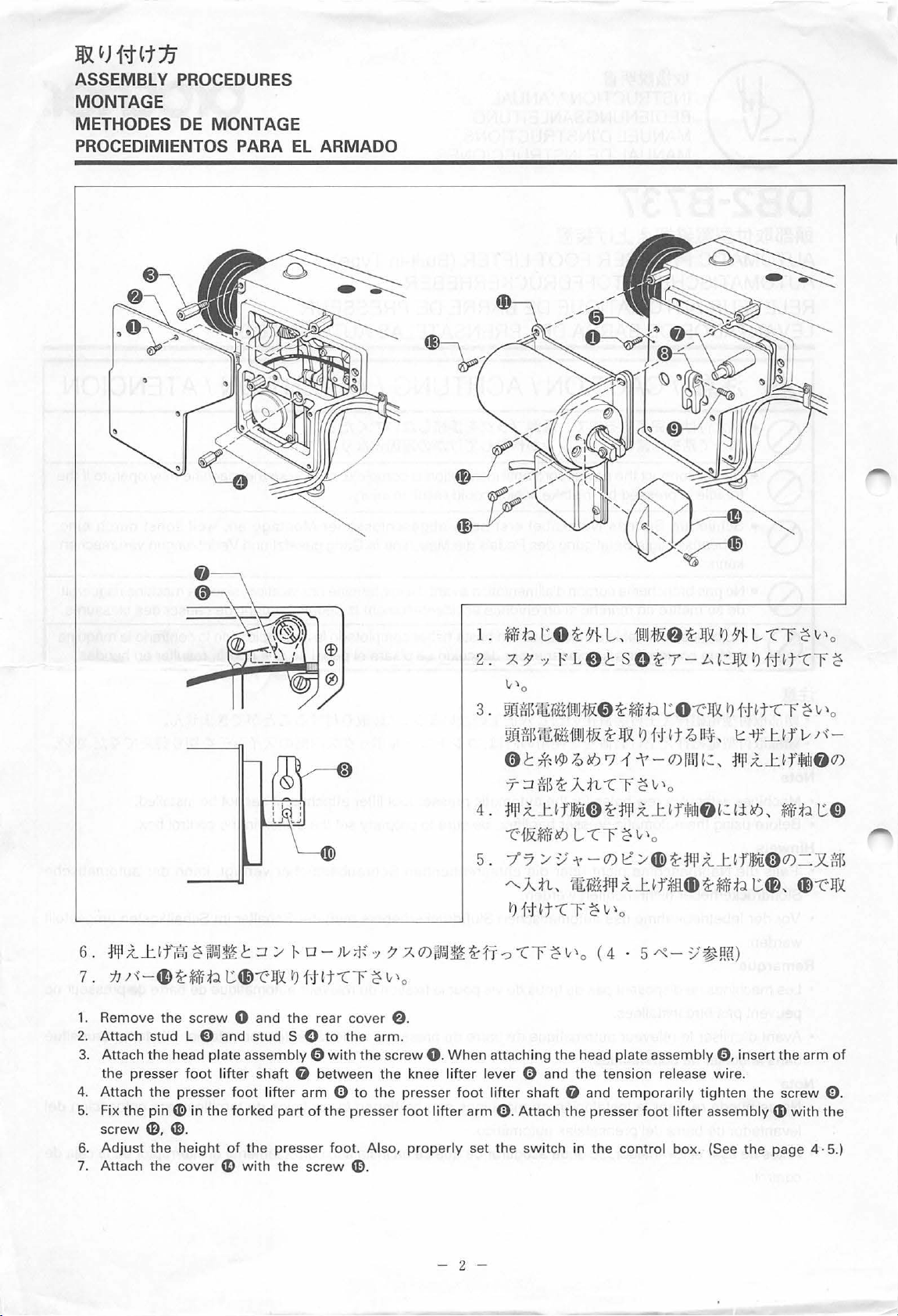
ASSEMBLY PROCEDURES
MONTAGE
METHODES
DE
MONTAGE
PROCEDIMIENTOS PARA
EL
ARMADO
6.
:J1JI
.Z...tlf~~wm~t:J/
7 .
tJ
r\'
-C}
~;f;lip
1.
Remo
ve
the screw 0 and
2.
Attach stud L E) and st
3.
Att
ach
the
head
the
4.
Attach
5. Fix
screw
6.
Adjust
Attach the
7.
presser
the
foot lifter
the presser
pin~
in the
CD.
e.
the
height
cover ~ wi
tG)-c·J&
ud
plate
assembly 0 with
shaft
foot lifter
fork
ed pa
of
the
presser
th
J-.o-Jv
I')
f•Jit"Z"r ~ v'o
the
rear
cover
S 0
to the arm
0 between
arm 0
rt
of
the
presser
foot
the
screw
G).
;f-'
·:~
7:AO)~~~f1·
@.
.
the
screw
0.
the
knee
to the presser
foot lifte
. Also,
properly
1.
*iii
z.
A
3.
~.lf
~J[:g:jS~:{1
0 t
7-:Jms~.An
4.
:j1JI
-c·1&;f;!i~
5. 7·7
"".A
I')
-=>
When
attaching
lift
er l
ever 0 and
foot
lifter shaft
r a
rm
0.
set the switch
~~ tO~)'}
-7
")
itiS~U:fr
liiHII
[!
if..~~~
;{_J:.~flw
:.<J""
n,
l,
""LOt
fi i
HIJ~
l
aH
s
t&:0~*WP
~I&
r; 1
"Z"r~v'
fi)~:J1l
"Z"r ~ v'o
-
0)
e:'
n
:Jill
x..
1•Ht"Z"r ~ v'o
-z-r~v'
Atta
o
(4 ·
the head plate
the
tension
0 a
nd
temporarily
ch the pres
in the
ser
control
i
l!IJ
~f)~li:X.IJ
e~
7-
t O
I')
N
~t
-t
-
0)
o
l;{__t~f
/
4D)
~:J1~
...t
~
f~n
4D
5
r-::-
assembly
release wire.
foot
lifter
box.
)"!-
t-
~=I&
""t"
lfll.IJ
f•Ht"Z"r~
~II~\
11\1
1
l~
:
1:::
~:,
:J111 ;t_U·
lif)
~:
li~,
X.....t
lf)Wfi)O)
~
Wi
P t
;-;
~mo
0,
insert
tighten
asse
mbly
(See
l
"Z"r ~ v'o
IJ1•nt·cr
-lf
J:.
~f
fiJqJif)O)
Wfp
~,
the
the screw
G)
wi
the
page 4 · 5.)
v'o
v
r\'-
t 0
=Jl
Q)
-c·lfJl.
arm
0.
th the
~
fflS
of
- 2 -
Page 3
~
~
1.
Die Schraube 8 losen und die hintere Abdeckung e abnehmen.
2.
Die Stifte
Die
3.
dem
4.
Den
anziehen.
5.
Den
CD,
CD
6.
Die
7.
Die Abdeckung
1.
Retirer
2.
Fixer le goujon E) et
3.
Fixer
electromagnetique
au
genou 0 et le fil de relachement de tension.
4.
Fixer
vis
5.
Fixer
pied presseur
6.
Regier
fa<;on
7.
Fixer le couvercle
1.
Ouitar
2.
Colocar
3.
Colocar
cabeza
cable de disminuci6n de tension.
4.
Colocar
momentaneamente
5.
Fijar
prensatelas
Ajustar
6.
control. (Consultar
7.
Colocar
L E) und S G anbringen.
Elektromagnetkupplung 0
Kniehebel 0 und dem Ruckstellzug befestigt werden.
Stoffdruckerheberarm e
Stitt
G)
in der Gabel des Stoffdruckerheberarms e anbringen und den Stoffdruckerheber
befestigen.
Hohe des Stoffdruckerhebers einstellen und den Schalter im Schaltkasten richtig einstellen. (Siche Seite 4 ·
CD
mit
der Schraube
Ia
vis 8 et le couvercle
le
l'embrayage electromagnetique de
de
Ia
le bras de releveur de pied presseur e sur l'arbre de releveur de pied presseur
mit
der Schraube 8 befestigen. Dabei muB der Arm der Heberachse G zwischen
an
der Stoffdruckerheberachse 8 anbringen und die Schraube 0 provisorisch
49
befestigen.
arriE~re
goujon G sur le bras.
tete, introduire le bras de l'arbre du releveur de pied presseur G entre le levier du releveur
e.
Ia
tete 0 a l'aide de
0.
Ia
goupille
Ia
correcte. (Voir
el
el
el
0,
el
el
pasador (l)
Ia
Ia
G)
dans
Ia
partie fourchue du bras du releveur de pied presseur
CD
a l'aide de les vis
hauteur du releveur de pied presseur. Regier aussi l'interrupteur situe dans
Ia
page 4 ·
CD
a l'aide de
tornillo 8 y desmontar
esparrago L E) y
embrague electromagnetico de cabeza 0 con
introducir
brazo del levantador del prensatelas e
CD
altura del levantador del prensatelas. Tambien, instalar correctamente
cubierta
con
el
brazo del eje dellevantador del prensatelas G entre
el
en
Ia
el
tornillo
Ia
pagina 4 ·
CD
el
tornillo
horquilla del brazo dellevantador del prensatelas
con
el
CD,
CD.
5.)
Ia
vis
49.
Ia
cubierta trasera
esparrago S G
0.
CD, CD.
5.)
tornillo
e.
en
el
e.
brazo.
el
tornillo
al
CD
mit
den Schrauben
5.)
Ia
vis
0.
Lors de
8.
AI
colocar
Ia
palanca dellevantador de rod ilia y
eje del levantador del prensatelas G y apretar
e.
Colocar
Ia
fixation de l'embrayage
Get
serrer momentanement
e.
Fixer !'ensemble du releveur de
le
boitier de commandes de
el
embrague electromagnetico de
el
conjunto dellevantador del
el
interruptor de
Ia
Ia
el
caja de
-
3-
Page 4

¥II
;t
J:.tf'~
c;
-~
ADJUSTING THE PRESSER FOOT LIFTER HEIGHT
DER
EINSTELLUNG
REGLAGE DE
LA
PARA AJUSTAR
*
~
O)~~~{j;b~v'
1.
~
~;:.;
~.:t.JJ!On~i~v'"l'-''~"'~
2.
'J
v / 11"'0)7"7
0~
~"'fJ:~fvJ~-o~:*"'C,
*!Q
t:C)~~ct>1t~tt-=:f~,
7"-
1
J
STOFFDRUCKERHEBERHOHE
HAUTEUR DU RELEVEUR
LA
ALTURA DEL LEVANTADOR DEL PIE DEL PRENSATELAS
c, ¥flitJ:Jf J:Jf.ii
~.=p~-IHI
L,
~
'J
~on~~tf&:J:oof)J:
c
~~i~
;.;V"~-·~~t:n1J[ti}~:51~"?t-=:;jj(!~-<:-,
~Q
¥JI.:tJ:£f~8~:
(lOmm)
LiTo
t:C)~*!ct>"lr~
DE
PIED PRESSEUR
i}~~·i--tt
'J
7l
'f
n~~"'
Iva
rnf"?
t-:flt:fi:~:
¥JI.:tJ:~f$dJ8~Jtl:i3t1J[tiJ~:IHI
'-''o
~ c ~it~
L
L
"lr
"lr ~ v'o
~
"'o
L,
7:J$
* The presser
1.
Turn the machine pulley by hand until the feed dog 8 is
Make sure that there is no gap between the needle plate and the presser foot E).
2.
When pulling the solenoid plunger 0 in the direction
Insert the knee lifter lever G into the arm 0 and tighten the screw
After tightening
*
Bei
falscher Einstellung
1.
Den
Transporteur 8 durch Drehen der Riemenscheibe tiefer als die Stichplatte e stellen und kontrollieren,
zwischen der Stichplatte und dem StoffdruckerfuB E) kein Abstand vorhanden ist.
2.
Den Magnetspulenstift 0 in P1eilrichting herausziehen und die Stoffdruckerheberachse 0 nach rechts drehen.
Den Kniehebel
Kontrollieren,
*
Le
pied presseur ne sera pas releve correctement (10mm) si
1.
Tourner
plaque a aiguille
Verifier qu'il
2.
Lorsqu'on tire le plongeur du soleno'ide 0 dans le sens de
dans le sens des aiguilles d'une montre.
lntroduire le levier du releveur
Apres avoir serre
foot
ob
Ia
poulie de
n'y
will
not
rise properly (10mm)
the
screw
0,
make sure that the presser
wird
der StoffdruckerfuB nicht richtig
G in den
die Stoffdruckerheberachse 0 nicht locker ist.
Arm
Ia
machine a
0 einsetzen und die Schraube 0 festziehen.
Ia
main jusqu'a
if
this adjustment is reglected.
of
the arrow, turn the presser
ce
que
Ia
griffe d'entrainement 8
e.
a pas de jeu entre
Ia
vis
0,
verifier
Ia
plaque a aiguille et le pied presseur
Ia
fleche, tourner l'arbre du releveur de pied presseur 0
au
genou G dans le bras 0 et serrer
qu'il
n'y
a pas de jeu
au
below
the
top
of
the needle plate's
foot
lifter shaft 0 clockwise.
e.
0.
foot
lifter shaft 0 does
(1
0 mm) angehoben.
ce
reglage est neglige.
not
wobble.
se
trouve sous le dessus de
e.
Ia
vis
0.
niveau de l'arbre du releveur de pied presseur
ob
~
Ia
0.
*
El
levantador de pie del prensatelas
1.
Girar
Ia
polea de
placa de aguja
Se
debe asegurar de que no
2.
AI tirar del em bolo del solenoide 0 en
derecha.
Colocar
Luego de apretar el tornillo
Ia
Ia
maquina a mano hasta que el alimentador 8 se encuentre debajo de
e.
palanca del levantador de rodilla G en
0,
no
se
levantara adecuadamente (10mm)
ha
quedado un espacio entre
el
senti do de
asegurarse de que el eje del levantador del prensatelas 0 no
Ia
flecha, girar el eje
Ia
- 4 -
Ia
placa de aguja y
palanca 0 y apretar
si
no
el
dellevantador
el
tornillo
se
realiza este ajuste.
Ia
parte superior de
prensatelas
del prensatelas 0 hacia
e.
0.
se
bambolee.
Ia
Ia
Page 5

:J /
~
[J
-J~;F
':/?
_AO)J'd~
SETTING THE SWITCH IN THE CONTROL BOX
SCHALTEREINSTELLUNG
REGLAGE
PARA
DE
L'INTERRUPTEUR SITUE DANS
INSTALAR
EL
IM
SCHALTKASTEN
INTERRUPTOR
DE
LA
CAJA
LE
BOlliER
DE
CONTROL
DE
COMMANDES
~
*~i$1&1t~illiit~X.J:Jf~il
"t"r~v\o
1.
rit>.t:O~~L
2.
£~1=fl~1ti!i
3.
7
* MD-601·MD-611
(Nit
..
1ltimtA1·;~7-7}~~~tt""Cv\Q$~liti£L"t"r~v\o)
..
~:{tv\'"(v\
?O~~t.l
t:O-eJ&
~{~fflTQtJJi~,i
77'8~~L""Cr~v\o
* Before using the automatic presser
power
1.
2.
3.
switch is turned
Remove the screw 0 and the cover
Set the switch
Attach the cover 8
to
OP
in the center
with
* Before using the MD-601 and MD-611, refer
* Vor
der
lnbetriebnahme des automatischen Stoffdruckerhebers muB
werden. (Dazu
1.
Die Schraube 0 losen und die Abdeckung
2.
Den Schalter in der Mitte der Leiterplatte auf
3. Die Abdeckung
muB
zuerst der Netzschalter ausgeschaltet werden.)
f)
mit
~1~ffli"
la>
A 1
·;~
7-0~
~
1t~t--cr
~
..
foot
off
before proceeding.)
f).
of
the screw
der
Schraube 0
0.
Qti~,i
"\0
AC4t-;F'.:C-7'0)J&f&~ijfjtf
lifter, be sure
the printed circuit board.
to
the Instruction manual
wieder
..
OP
1JlU
f)
abnehmen.
OP
befestigen.
1l·T:J
':A
to
stellen.
;,-
t-
a-
Jv*'
·;1
7 A
I*J$0)A
71
1--
..
~-tt"t"r
properly set the switch in the control box. (Make sure the
of
AC
der
~
v\o
(9,
10~-V)
servomotor on page
Schalter
im
Schaltkasten richtig eingestellt
1
1:.t-3JJ~r~v\o
28,
·;~1-
~~~~X.
30.
* Vor der lnbetriebnahme des MD-601 und MD-611, verweist auf die Bedienungsanleitung AC-servomotor auf Seite
*
Avant
d'utiliser le releveur automatique de barre de presseur, veiller a n3gler correctement l'interrupteur situe dans
le boitier de commandes.
1.
Retirer
2.
Deplacer l'interrupteur situe
3.
Fixer le couvercle 8 a l'aide de
* Avant d'utiliser
page
29,
Ia
32.
vis 0
et
le
releveur MD-601 et MD-611, veuitlez
(Veiller a couper !'alimentation avec l'interrupteur d'alimentation avant de proceder.)
le couvercle
f).
au
centre de
Ia
vis
Ia
plaque de circuit
0.
Ia
vos referer a
imprime
Ia
Manuel d'instructions de servomoteur
vers le repere
OP.
AC
28,
31.
annex
* Antes de usar
Ia
caja de control.
1.
Ouitar el
2.
lnstalar el
3.
Colocar
* Antes de usar
ellevantador
(EI
tornillo
Ia
0 y desmontar
interrupter
cubierta 8 con el
el
MD-601 y MD-611, habra que mirar el manual
de
Ia
barra del prensatelas automatico
interrupter
en el centro del tablero de circuitos impresos al lado
principal debe estar desconectado para este procedimiento.)
Ia
cubierta
tornillo
0.
f).
- 5 -
se
debe instalar correctamente el interrupter en
de
instrucciones servomotor de
OP.
AC
de
Ia
Pagira
29,
33.
Page 6

A.
tltStEJII
I Solenoidsatz
I Conjunto aereo
J:.lf~1K\
I
Presser
fur
die anhebung
dellevantador
foot
lifting
solenoid set
des
stoffdruckerfuBes
del pie I Conjunto solenoide
dellevantador
f_j
1-11-10
--
-·
1-11-11
-f1
1-11-8 1-11-7
- 6 -
1
1-11-12
~m
1-11-11-11-2 ' f
1-11-3 1-
1-11-4 1-11-5
12
'I
117-737-943
Page 7

A.
~Hif,IJ:lfiiJiKi
I
Presser
foot
lifting
solenoid set
I Solenoidsatz fOr die anhebung des stoffdrOckerfuBes
I Conjunto aereo
REF.NO.
1
1
183947001
183948001
CODE
dellevantador
Q'TY
<II~
1"
·-:~7-i>t
1
T'/~~-tj".IJ7-7i!';/
<II~
1"
·:;
1
T'/~;ti.t.IJ7Ti!';/
del pie I
I::/;C1"
Con
junto
> <With ''Knne switch assy
1--A
71M
L,
>
1--B
solenoide
PRES.
FOOT
<With-out
PRES.
FOOT
dellevantador
NAME
LIFTER
..
Knne
LIFTER
OF
PARTS
SOL.
SET
switch assy
SOL.
SET
RM
..
>
A
..
>
B
1-----------
1-1
1-1-1
1-1-1-1
1-1-1-2
1-1-1-3
1-1-1-4
1-1-1-5
1-1-1-6
1-1-1-7
1-1-2
1-1-3
1-2
1-3
1-4
1-5
1-6
1-7
1-8
1-9
1-10
1-10-1
1-10-1-1
1-10-2
1-10-3
1-10-4
1-10-5
1-10-6
1-10-7
1----
----------
S40832051
S40833051
062780812
018761822
048050142
1-----------------------
1
T'/~;ti.t.IJ7-7?
1
T'/~;t-tt.IJ7-7?
1 7-IX::J 635-28X8
J77-;f.J!I
3
2
"'
;C
'7
~?
1--
5.95X18
3 7
062671012 2 -j-1'\::J 357-40X10
002300603
062680663
1 + 7-IX::J 3X6
1 "TI'\::J437-40X6
062670612 1 -j-1'\::J 357-40X6
1
S02592059
9-/~1J1"tJJ{-
062670612 2 -j-1'\::J 3.57-40X6
1
S32924001
062711212 1 7
S16641001
;t-tj".IJ7-77T'
I'\
::J
476-32X12
2
~
~
';/
1-=L
062781412 1 7-1'\::J 635-28X14
2
~~·;,~
S16642001
062781012 3 7
S16643009
062670812
S16644102
S16615002
S11589000
S32923001
1
2 7
1
1
1
1 ;t-+.t.I
048080342 1
110197001
153675001
S16645000
025100132
1
2
1
1
1-=S
I'\
::J
63 5-28X 1 0
tJ
J{-
I'\
::J
3.57 -40X8
~777:..-~ti'71"~
ti'71"~'..17?~
~7..
"'~-)!,
7'-7~?
~
;C
'7
E8
-t!
';/
"'
tJ
7 -
y-;-
~
;C
*
~4.37
ti'71"~J~·;~~;...
1::7-tfti*~3710
cs
~
~T
-------------------------------------
PRES.
FOOT
PRES.
FOOT
SCREW,
BOLT,
RETAINING
SCREW,
SCREW,
SCREW,
SCREW,
TERMINAL
SCREW,
PRESSER
SCREW,
STUD,
SCREW,
STUD,
SCREW,
PAN
SOCKETSM5.95X18
RING,
PAN
PAN
PAN
PAN
BLOCK
PAN
FOOT
PAN
L
PAN
S
PAN
LIFTER
LIFTER
SOL.
ASSY
SOL.
ASSY
SM6.35-28X8
C5
SM3.57-40X1 0
M3X6
SM4.37-40X6
SM3.57-40X6
COVER
SM3.57-40X6
LIFTER
ARM
SM4.76-32X12
SM6.35-28X14
SM6.35-28X10
T
COVER
SCREW,
REAR
REAR
DUST
PRESSER
RETAINING
SET
SET
REAR
WASHER,
PAN
COVER
COVER
SEAL
FOOT
SCREW
SCREW,
COVER
PLAINS
SM3.57-40X8
SET
UNIT
LIFTER
RING,
SHAFT
E8
COLLAR
SOCKET
SM4.37
PACKING
10
--
----------
1-11
1-11-1
1-11-2
1-11-3
1-11-4
1-11-5
1-11-6
1-11-7
1-11-8
1-11-9
1-11-10
1-11-11
1-11-12
1-12
----------
1----
S07045009
142026003 1
142027001
100463001
114967001
110087001
S07027001
062401006
025040233
028040243 4
021400164
S07030009
149799000
034422503
•
1-----------------------
<SetAJftlttfSetBJD
1
l::-tf7..1"';17?
l::-tf7..1"';17~7"~?
1
l::-tf7..1"';17~7"~?ry?"
1
tJ?
;f.Jj, ~ 7.94
1
l::ifJ77"~
1
;j{
Jj,
1
1::
-If~
"'
5.95
1"
~·;JH
'/
T
~
~
IJ
'')
~7'~
T
1"
~
4 7-IX::J4X10
4
1::7ifti*7.:Z.74
/{-*ifti-*2-4
4
-;-•;,~
~ 1 ~.:1.4
1
~1"';17-::J-
1
~
1 7
4
+i.t7~?-*
!-=?
·:~
"fs
~4.1X25
~
- 7 -
~-------------------------------------
3/
> <With Set A & option parts for Set B >
KNEE
KNEE
KNEE
BOLT,
KNEE
BOLT,
KNEE
SCREW,
WASHER,
WASHER,
NUT, 1 M4
SWITCH
BEADBAND,S
WOOD
SWITCH
SWITCH
SWITCH
SM7.94
LIFTER
PLATE
SM5.95
LIFTER
PAN
SWITCH
M4X10
PLAIN
SPRING
CORD
SCREW,
ASSY
SHAFT
SHAFT
STOPPER
M 4
2-4
ASSY
FLAT
--
BRACKET
PLATE
M4.1X25
117-737-943
Page 8

INSTRUCTION MANUAL
BEDIENUNGSANLEITUNG
MANUEL D'INSTRUCTIONS
MANUAL_DE INSTRUCCIONES
••
77-tj--J:Mflit~fl:
BROTHER
••
INDUSTRIES,L
TO.
ijl~~~B~
:Y:467
~
O"JMmJifflf!~fRJJ¥1T
Printed in Japan I Gedruckt in
131111~
Jap~
I lmprime au Japon I Impreso en Jap6n
TEL(052)824-2392
117-737
S90737-161
1997.01.
B®
 Loading...