

Brother DB2-797, DB2-798 Service Manual
SERVICE
MANUAL
FOR
082-8797
082-8798
SINGLE NEEDLE ADJUSTABLE
TOP
AND
BOTTOM
FEED
LOCK STITCH MACHNE
. .
~
·
'
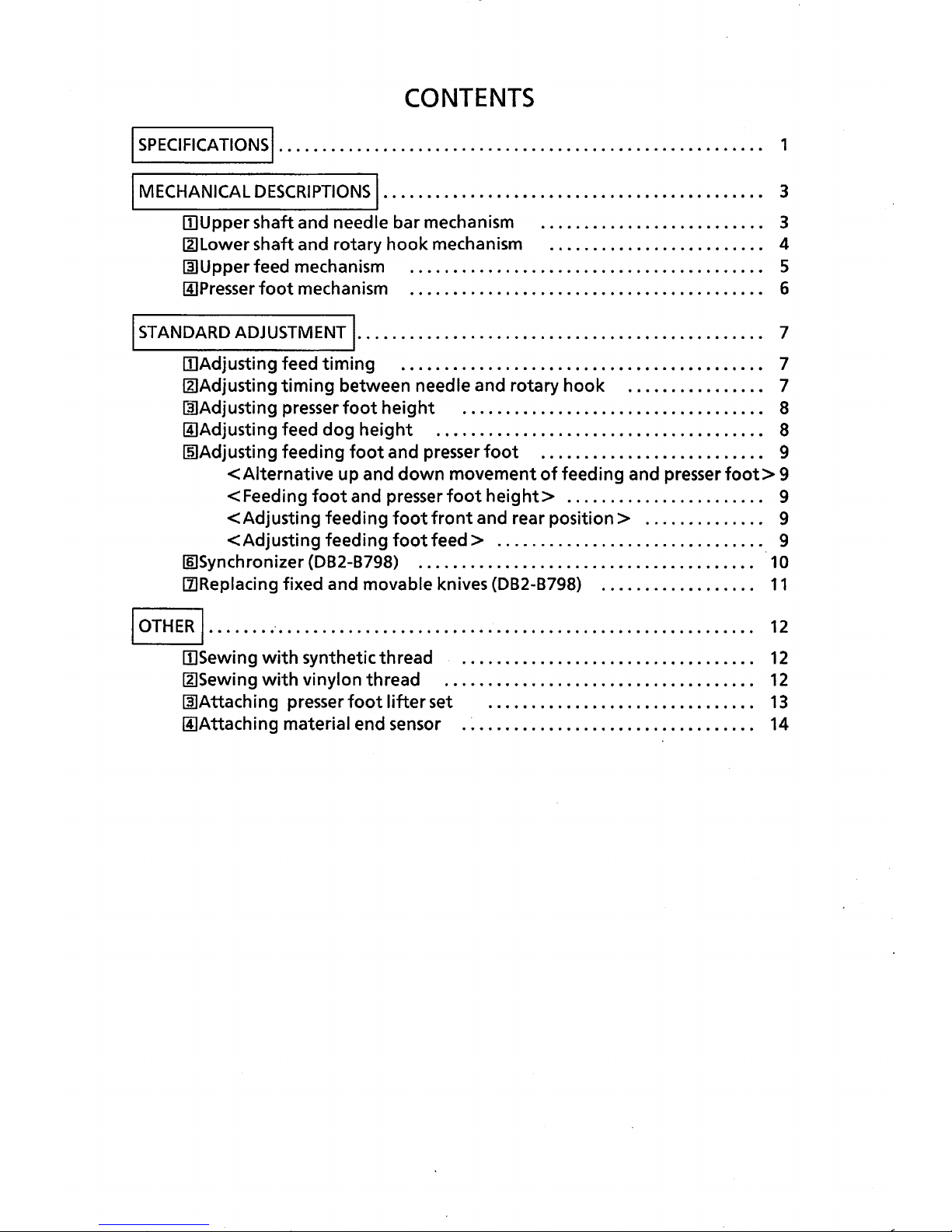
CONTENTS
I
SPECIFICATIONS,........................................................
1
I
MECHANICAL
DESCRIPTIONS
I·.
. . . . . . . . . . . . . . . . . . . . . . . . . . . . . . . . . . . . . . . . . . 3
II)
Upper shaft and needle bar mechanism . . . . . . . . . . . . . . . . . . . . . . . . . . 3
IZ]Lower shaft and rotary
hook
mechanism . . . . . . . . . . . . . . . . . . . . . . . . . 4
~Upper
feed mechanism . . . . . . . . . . . . . . . . . . . . . . . . . . . . . . . . . . . . . . . • . 5
II]
Presser
foot
mechanism . . . . . . . . . . . . . . . . . . . . . . . . . . • . . . . . . . . . . . . . . 6
I
STANDARD
ADJUSTMENT
I·.............................................. 7
IIJAdjusting feed
timing
. . . . . . . . . . . . . . . . . . . . . . . . . . . . . . . . . . . . . . . . . . 7
IZ]Adjusting
timing
between needle and rotary hook . . . . . . . . . . . . . . . . 7
~Adjusting
presser
foot
height
. . . . . . . . . . . . . . . . . . . . . . . . . . . . . . . . . . . 8
IIJAdjusting feed
dog
height
. . . . . . . . . . . . . . . . . . . . . . . . . . . . . . . . . . . . . . 8
rn:JAdjusting
feeding
foot
and presser
foot
. . . . . . . . . . . . . . . . . . . . . . . . . . 9
<Alternative
up and
down
movement
of
feeding and presser
foot>
9
<Feeding
foot
and presser
foot
height>
. 0
0. 0 ••••••••
0
••
0. 0 0...
9
<Adjusting
feeding
foot
front
and rear
position>
0
••• 0 •••••
0...
9
<Adjusting
feeding
foot
feed>
....
0
••••
0 0
••••••
0
••• 0 •••••
0 • • • • 9
II)Synchronizer
{082-8798)
. . . . . . • . • . . . . . . . . . . . . . . . . . . . • . . . • . . . . . • 10
[l]Replacing
fixed and movable knives
{082-8798)
. . . . . . . . . . . . • . . . . .
11
'OTHER,
....... .-.......................................................
12
[!]Sewing
with
synthetic thread . . . . . . . . . . . . . . . . . . . . . . . . . . . . . . . . . .
12
IZ1Sewing
with
vi nylon thread . . . . . . . . . . . . . . . . . . . . . . . . . . . . . . . . . . . .
12
~Attaching
presser
foot
lifter
set . . . • . . . . . . . . . . . . . . . . . . . . . . . . . . .
13
IIJAttaching material end sensor . . . . . . . . . . . . . . . . . . . • . . . • . . . . . . . . . . 14
I
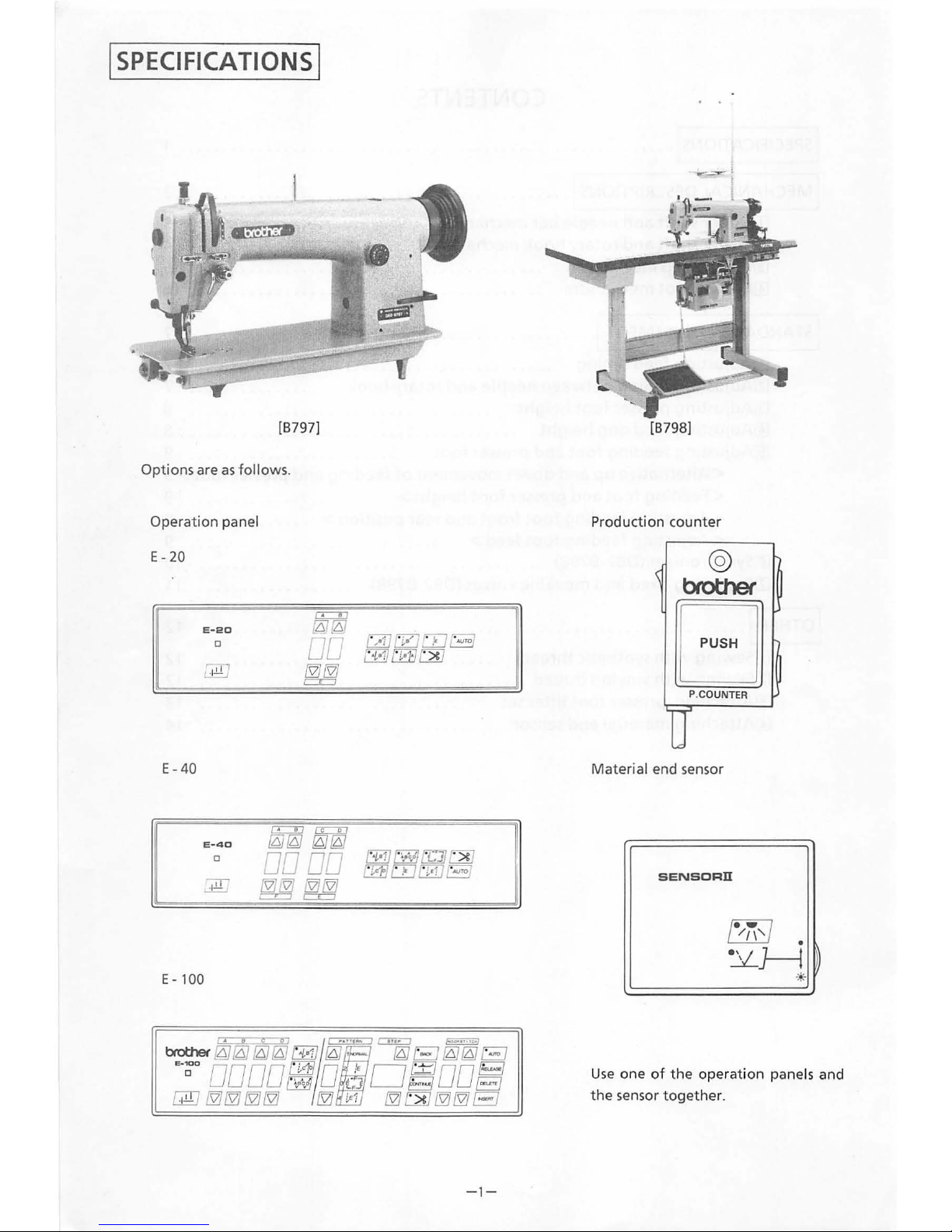
SPECIFICATIONS
I
[B
797]
Options are
as
follows.
Operation panel
E- 20
E-
40
E-20
0
E -
40
0
E-
100
-1
-
[B798]
Production counter
@
brother
EJ
P.COUNTER
Material end sensor
SENSORll
Us
e one
of
the
operation
panels and
the sensor t
ogether
.
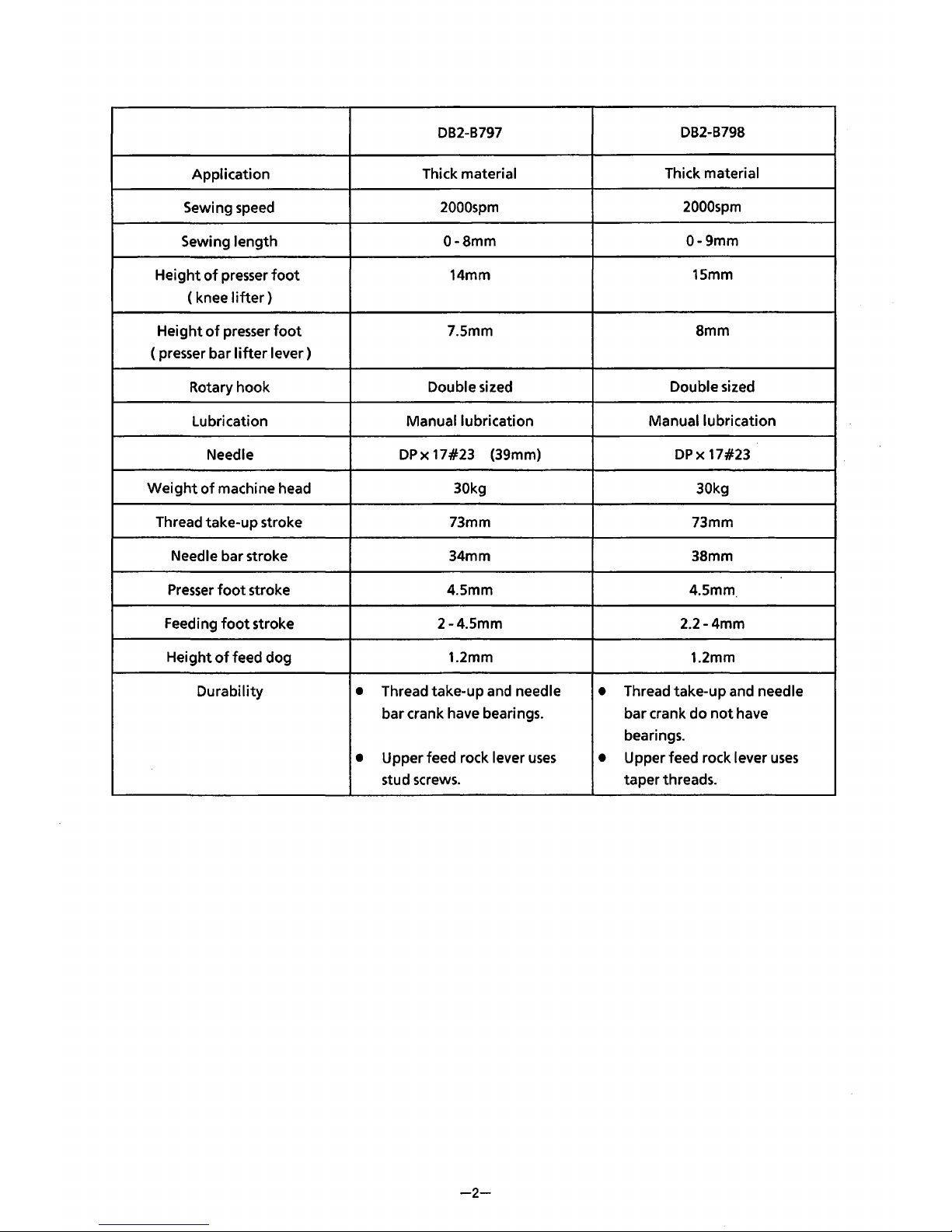
DB2-B797
DB2-B798
Application
Thick material
Thick material
Sewing speed
2000spm
2000spm
Sewing
length
0-Smm
0-9mm
Height
of
presser
foot
14mm
15mm
(knee
lifter)
Height
of
presser
foot
7.5mm
Smm
(presser bar
lifter
lever)
Rotary hook
Double sized
Double sized
Lubrication
Manual lubrication
Manual lubrication
Needle
DPx
17#23
(39mm)
DPx
17#23
Weight
of
machine head 30kg 30kg
Thread take-up stroke 73mm 73mm
Needle bar stroke
34mm
38mm
Presser
foot
stroke 4.5mm 4.5mm
Feeding
foot
stroke
2-4.5mm
2.2-4mm
Height
of
feed dog
1.2mm
1.2mm
Durability
•
Thread take-up and needle
•
Thread take-up and needle
bar crank have bearings. bar crank
do
not
have
bearings.
•
Upper feed rock lever
uses
•
Upper feed rock lever
uses
stud screws.
taper
threads.
-2-
I MECHANICAL
DESCRIPTIONS!
[II
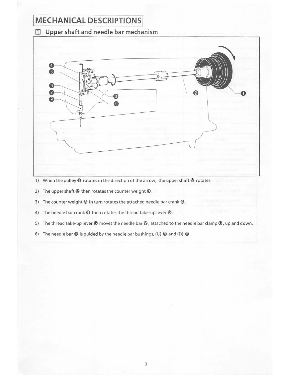
Upper shaft and needle bar mechanism
1)
When
the
pulley 0 rotates
in
the
direction
ofthe
arrow,
the
upper
shaft@
rotates.
2)
The
upper
shaft@
then
rotates
the
counter
weight@.
3)
The counter
weight@
in
turn
rotates
the
attached needle bar crank e.
4)
The needle bar crank e
then
rotates
the
thread take-
up
lever
0.
5)
The thread
take-up
lever 0 moves
the
needle
bar
f),
attached
to
the
needle bar clamp
0,
up
and
down.
6)
The needle bar
f)
is
guided by
the
needle bar bushings, (U) @ and
(D)
@.
- 3-
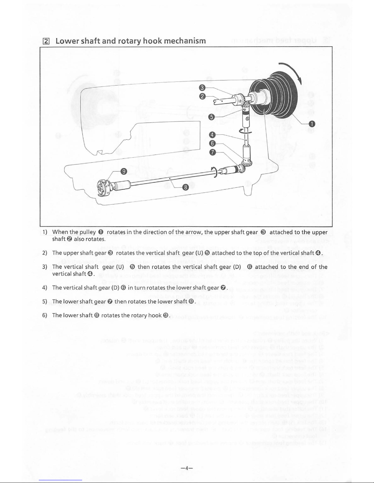
~
lower
shaft and rotary hook mechanism
1)
When
the
pulley 0
rotates
in
the
direction
of
the
arrow,
the
upper
shaft
gear @ attached
to
the
upper
shaft@
also
rotates
.
2)
The
upper
shaft
gear@
rotates
the
vertical sha
ft
gear
(U) 0 attached
to
the
top
of
the
vertical
shaft
e.
3)
The vertical sha
ft
gear
(U)
0
then
rotates
the
vertical
shaft
gear
(D)
@
attached
to
the
end
of
the
vertical
shaft
e.
4)
The vertical
shaft
gear
(D)@ in
turn
rotates
the
lower
shaft
gear
f).
5)
The
lower
shaft
gear
f)
then rotates
the
lower
shaft@.
6)
The l
ower
shaft@
rotates
the
rotary
hook@.
-4-
 Loading...