

Page 1

Operation Manual
Cover stitch machine / Top cover stitch machine
Product Code: 884-B30 / B31
Manual de instrucciones
Máquina recubridora / Máquina recubridora superior
Product Code (Código de producto): 884-B30 / B31
EnglishEspañol
Be sure to read this document before using the machine.
We recommend that you keep this document nearby for future reference.
Lea este documento antes de utilizar la máquina.
Recomendamos que tenga este documento a mano por si necesita consultarlo más adelante.
Page 2
IMPORTANT SAFETY INSTRUCTIONS
When using the sewing machine, basic safety precautions should always be followed, including the following.
Read all instructions before using this machine.
19. Do not disassenble the machine.
If the LED light unit (light-emitting diode) is damaged, it
DANGER
To reduce the risk of electric shock.
The sewing machine should never be left unattended
when plugged in. Always unplug this sewing machine
from the electrical outlet immediately after using and
before cleaning.
WARNING
To reduce the risk of burns, fire, electric shock,
or injury to persons.
1. Do not allow to be used as a toy. Close attention is
necessary when the sewing machine is used by or near
children.
2.
Use this se
as described in this manual. Use only accessories
recommended by the manufacturer as contained in this
manual.
3. Never operate this sewing machine if it has a damaged
cord or plug, if it is not working properly, if it has been
dropped or damaged, or dropped into water. Return
the sewing machine to the nearest authorized dealer
or service center for examination, repair, electrical or
mechanical adjustment.
4. Never operate the sewing machine with any air openings
blocked. Keep ventilation openings of the sewing
machine and foot controller free from the accumulation
of lint, dust, and loose cloth.
5. Never drop or insert any object into any openings.
6. Do not use outdoors.
Do not oper
7.
used or where oxygen is being administered.
8.
o disconnect, turn the main switch to the symbol “O”
T
position which represents off, then remove plug from
outlet.
9. Do not unplug by pulling on cord. To unplug, grasp the
plug, not the cord.
10. Keep fingers away from all moving parts. Special care is
required around the sewing machine needle.
11. Always use the proper needle plate. The wrong plate can
cause the needle to break.
12. Do not use bent needles.
13.
Do not pull or push f
the needle causing it to break.
14.
Switch the se
when making any adjustments in the needle area, such
as threading needle, changing needle, or changing
presser foot, etc.
Alw
15.
outlet when removing covers, lubricating, or when
making any other user servicing adjustments mentioned
in the instruction manual.
Electr
16.
- This machine should be connected to an AC power
source within the range indicated on the rating label.
Do not connect it to a DC power source or inverter. If
you are not sure what kind of power source you have,
contact a qualified electrician.
This machine is appro
-
purchase only.
This se
17.
children or infirm persons without supervision.
18. Young children should be supervised to ensure that they
do not play with this sewing machine.
wing machine only for its intended use
ate where aerosol (spray) products are being
abric while stitching. It may deflect
wing machine to the symbol “O” position
ays unplug the sewing machine from the electrical
ical Hazards:
ved for use in the country of
wing machine is not intended for use by young
20.
m
ust be replaced by authorized dealer.
CAUTION
To use the machine safely
1. (For U.S.A. only)
This appliance has a polarized plug (one blade wider
than the other) to reduce the risk of electric shock, this
plug is intended to fit in a polarized outlet only one way.
If the plug does not fit fully in the outlet, reverse the plug.
If it still does not fit, contact a qualified electrician to
install the proper outlet.
Do not modify the plug in any way.
2. Make sure you watch the needles carefully while you are
sewing. Do not touch the handwheel, needles, knives, or
other moving parts.
3.
urn off the main power and unplug the cord in the
T
following circumstances:
- When you have stopped using the machine
- When you are replacing or removing the needle or any
other part
- If there is a power failure while you are using the
machine
- If you are checking or cleaning the machine
- Leaving the machine unattended
4. Do not store anything on the foot controller.
5.
Fully plug the machine directly into the w
extension cords.
6.
ater is dropped on the machine, unplug the machine
If w
immediately, and contact your local authorized dealer.
7.
Do not put fur
8. Do not bend the cord, or pull on the cord to unplug.
9.
Do not touch the cord with w
10. Place the machine near to the wall outlet.
11. Do not place the machine on an unstable surface.
12. Do not put on the soft cover.
13. If you notice any abnormal sound or condition, consult
your local authorized dealer.
To give your machine a longer life
1. Do not store this machine in direct sunlight or in high
humidity conditions. Do not use or store the machine
near a heater, iron, halogen lamp or other hot object.
2.
Use only mild soaps or detergents to clean the case
Benzene, thinner, and scouring powders can damage
the case and machine, and should never be used.
3. Do not drop or hit the machine.
4.
ays consult this manual before you replace or fit the
Alw
presser foot, needle, or any other parts to make sure
you fit them correctly.
To repair or adjust the machine
If the machine breaks down or needs adjustment,
first follow the troubleshooting table to inspect and
adjust the machine yourself. If the problem persists,
consult your local authorized dealer.
niture on the cord.
et hands.
all. Do not use
.
Page 3
SAVE THESE INSTRUCTIONS
This machine is intended for household use.
FOR USERS IN COUNTRIES EXCEPT CENELEC COUNTRIES
This appliance is not intended for use by persons (including children) with
reduced physical, sensory or mental capabilities, or lack of experience and
knowledge, unless they have been given supervision or instruction concerning
use of the appliance by a person responsible for their safety. Children should be
supervised to ensure that they do not play with the appliance.
FOR USERS IN CENELEC COUNTRIES
This appliance can be used by children aged from 8 years and above and persons
with reduced physical, sensory or mental capabilities or lack of experience and
knowledge if they have been given supervision or instruction concerning use of
the appliance in a safe way and understand the hazards involved. Children shall
not play with the appliance. Cleaning and user maintenance shall not be made by
children without supervision.
CAUTION
When leaving this sewing machine unattended, the main power and light switch of the machine must be
switched off or the plug must be removed from the socket-outlet.
English
When servicing the sewing machine, or when removing covers, the machine or the electrical set must be
disconnected from the supply by removing the plug from the socket-outlet.
FOR USERS IN THE UK, EIRE,
MALTA AND CYPRUS ONLY
IMPORTANT
- In the event of replacing the plug fuse, use a fuse approved by ASTA to BS 1362, i.e. carrying the mark,
rating as marked on plug.
- Always replace the fuse cover. Never use plugs with the fuse cover omitted.
- If the available electrical outlet is not suitable for the plug supplied with this equipment, you should contact
your authorized dealer to obtain the correct lead.
1
Page 4
CONGRATULATIONS ON CHOOSING THIS COMPACT
AVERTISSEMENT:
PARTIES EN MOUVEMENT. POUR
ÉVITER TOUTE BLESSURE:
FERMER LE CAPOT AVANT DE
COUDRE.
DÉBRANCHER AVANT ENTRETIEN.
OVERLOCK MACHINE
Your machine is a high quality, easy-to-use product. To fully enjoy all the features, we suggest that you study
this booklet.
If you need more information regarding the use of your machine, your nearest authorized dealer is always
happy to be of service.
Enjoy yourself!
CAUTION
When threading or replacing needle, the main power and light switch of the machine must be switched off or
the plug must be removed from the socket-outlet.
When the machine is not in use, it is recommended that the electric supply plug is disconnected from the
wall socket to avoid any possible hazards.
Notes on the motor
- The maximum operating speed of this sewing machine is 1,000 stitches per minute, which is quite fast
compared to the normal operating speed of 300 to 800 stitches per minute for the ordinary sewing machine.
- The bearings in the motor are made of a special material (oil-impregnated alloy mounted in felt heat-treated
with oil) that enables them to withstand long hours of continuous operation.
- Continuous operation of the sewing machine can cause heat to build in the motor area, but not enough to
adversely affect its performance.
It is important to keep fabric and paper away from the air openings on the back and sides of the machine so
air can get to these openings.
- When the motor is running, sparks can be seen through the air openings in the motor bracket on the side
opposite the handwheel. These sparks are produced by the carbon brushes and the commutator, and are part
of the machines normal operation.
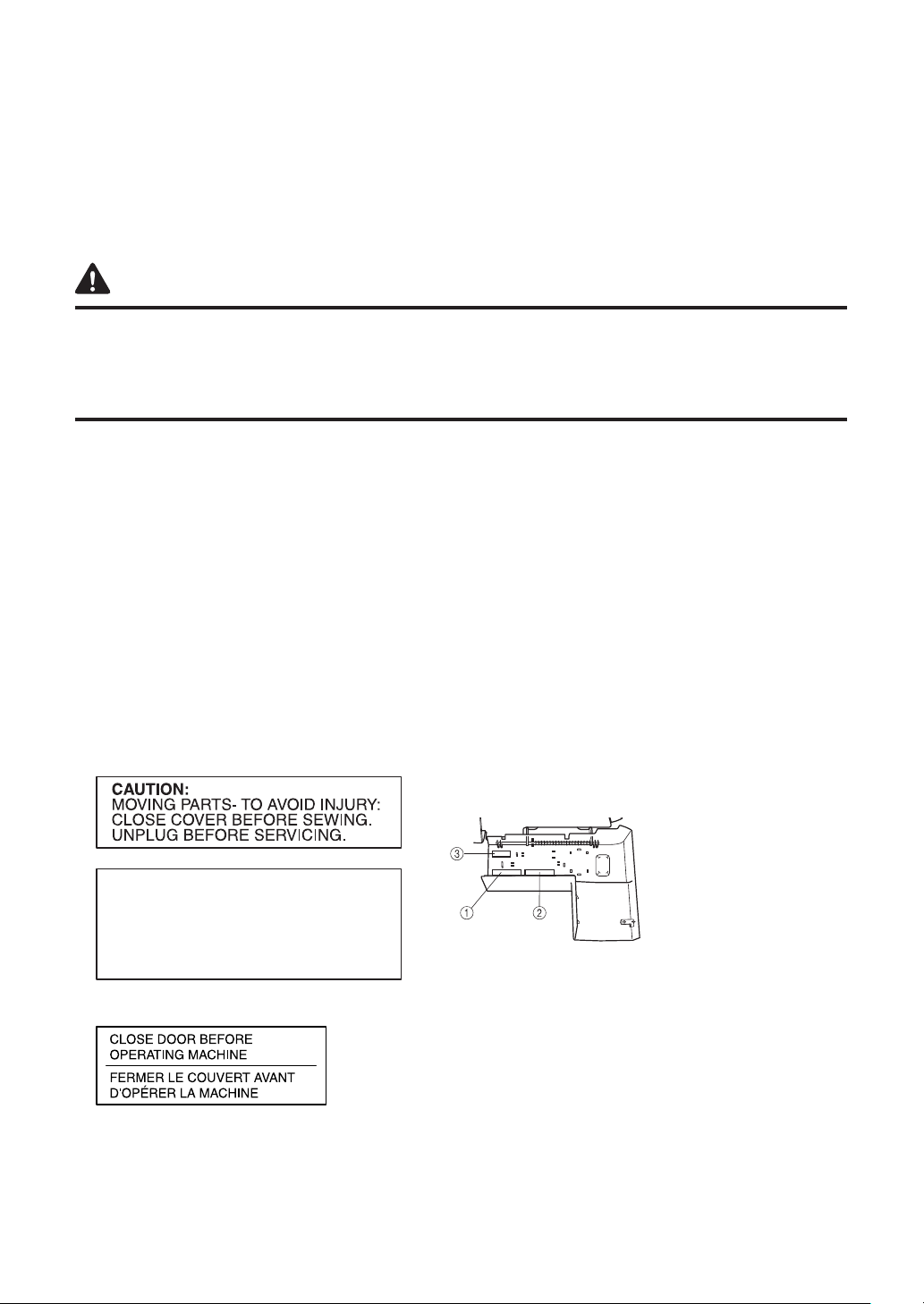
WARNING LABELS
The following warning labels are on the machine.
Be sure to observe the precautions described in the labels.
Caution (U.S.A. and CANADA only)
1
2
Face plate sticker (U.S.A. and CANADA only)
3
(for complying with UL and CSA requirements)
Label locations
2
Page 5

Contents
Chapter 1 : NAMES OF PARTS AND THEIR FUNCTIONS .................................................... 4
Machine (Cover stitch model) (Product code: 884-B30) .....................................................4
Accessories (Cover stitch model) .......................................................................................5
Machine (Top cover stitch model) (Product code: 884-B31) ...............................................6
Accessories (Top cover stitch model) .................................................................................7
Powering the machine.........................................................................................................8
Turning direction of handwheel ...........................................................................................8
Opening/Closing front cover ...............................................................................................8
Attaching/Removing a presser foot .....................................................................................8
Free-arm sewing (removing the bed extension) ..................................................................9
Looper thread tension adjustment lever ..............................................................................9
Stitch length ........................................................................................................................10
Differential feed ...................................................................................................................10
Adjusting the presser foot pressure ....................................................................................11
Adjusting the tension dials ..................................................................................................11
Needle ................................................................................................................................12
Removing/Installing the needle ...........................................................................................12
Chapter 2 : PREPARATION BEFORE THREADING .............................................................. 13
Thread tree .........................................................................................................................13
Using the thread spool cap .................................................................................................13
Spool mat ............................................................................................................................13
Using the spool mat ............................................................................................................13
Using the thread net ...........................................................................................................14
Before threading .................................................................................................................14
Chapter 3 : THREADING (Cover stitch model) ..................................................................... 15
Threading the looper ...........................................................................................................15
Threading the needles ........................................................................................................16
Chapter 4 : THREADING (Top cover stitch model) .............................................................. 17
Threading the looper ...........................................................................................................17
Threading the needles ........................................................................................................18
Attaching/Removing the top cover spreader and top cover thread guide ...........................19
Threading the top cover spreader .......................................................................................20
Chapter 5 : TYPE OF STITCHES COMPARISON CHART ..................................................... 21
Chapter 6 : SEWING ............................................................................................................... 24
Sewing fl at fabric (for example, trial sewing) .......................................................................24
Removing the fabric from the machine (Cover stitch model) ..............................................24
Removing the fabric from the machine (Top cover stitch model) ........................................25
Sewing a cover stitch ..........................................................................................................27
Sewing tubular garments (for example, cuffs) .....................................................................27
Stabilizing the beginning and end of stitching .....................................................................28
Chapter 7 : TROUBLESHOOTING .......................................................................................... 29
Chapter 8 : MAINTENANCE ................................................................................................... 30
Cleaning ..............................................................................................................................30
SPECIFICATIONS .................................................................................................................... 31
English
3
Page 6
CHAPTER 1
NAMES OF PARTS AND THEIR FUNCTIONS
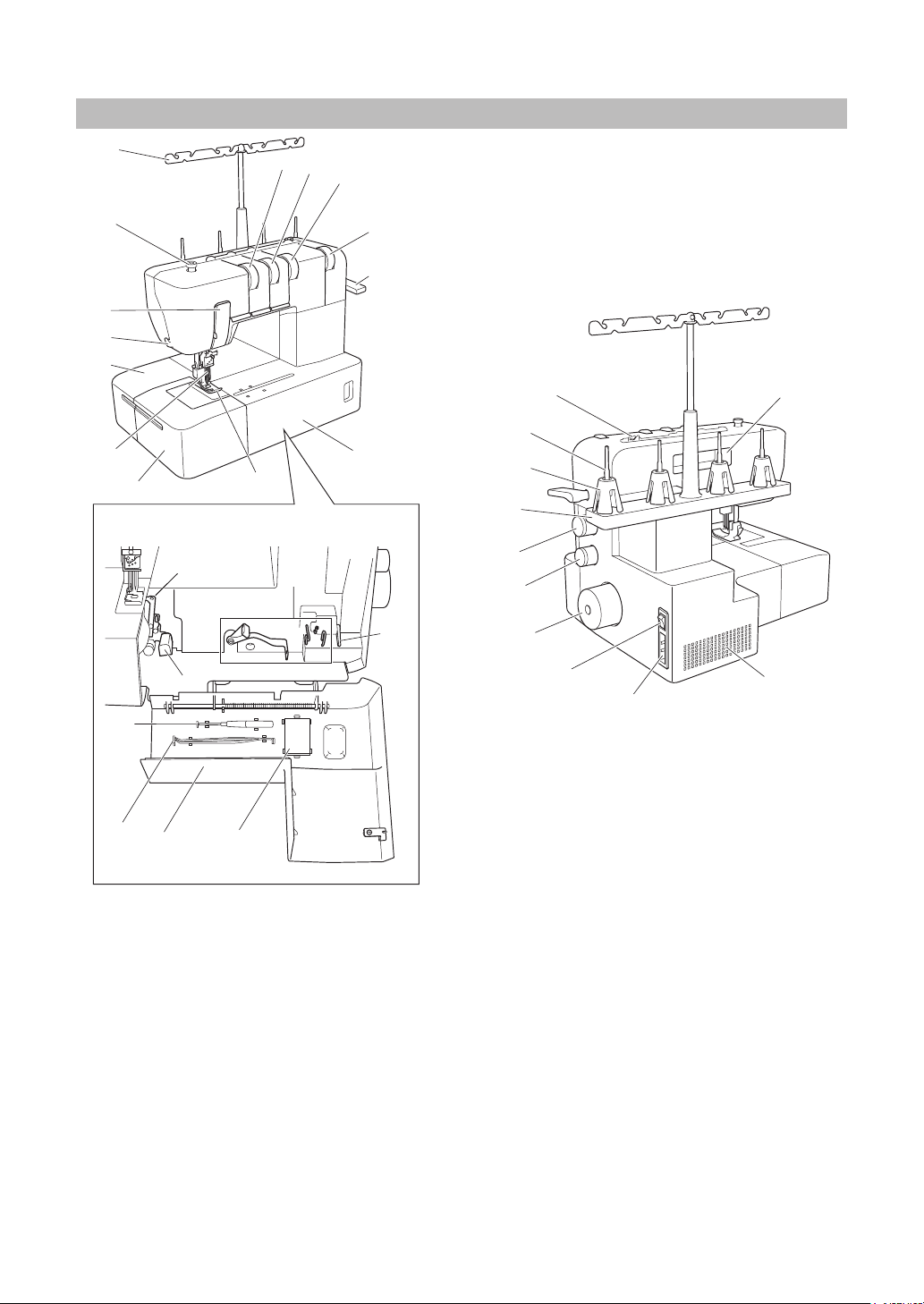
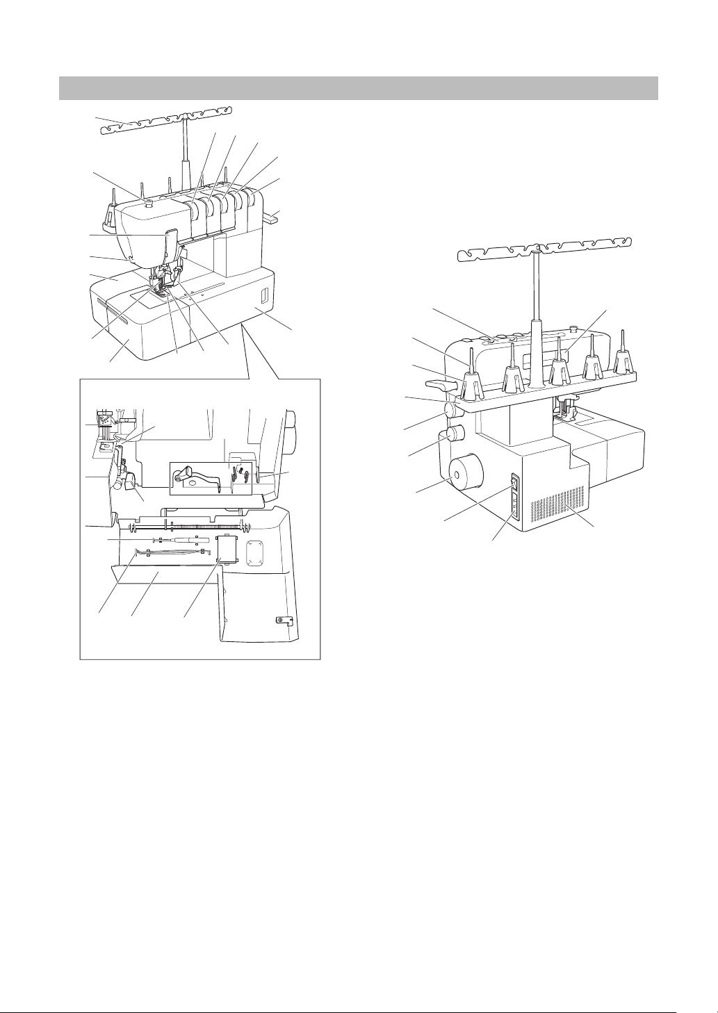
Machine (Cover stitch model) (Product code: 884-B30)
1
9
0
A
2
3
4
5
6
7
8
B
C
E
F
D
G
H
N
Inside of the front cover
I
J
K
L
M
O
<C>
R
S
Q
P
<B>
T
Thread tree
1
Presser foot pressure adjustment screw
2
Thread take-up cover
3
Thread cutter
4
Material plate cover
5
Needles
6
Bed extension
7
Presser foot
8
Left needle thread tension dial
9
Center needle thread tension dial
0
Right needle thread tension dial
A
Looper thread tension dial
B
Presser foot lever
C
Front cover
D
Thread guide
E
Spool pin
F
Spool cushion
G
<A>
4
Spool support
H
Stitch length adjustment dial
I
Differential feed ratio adjustment dial
J
Handwheel
K
Main power and light switch
L
Foot controller socket
M
Handle
N
Air openings
O
Inside of the front cover
Looper thread tension adjustment lever
P
Looper thread take-up
Q
Looper
R
Looper release lever
S
Front cover compartment
t
You can store the included accessories in this
front cover compartment. <A>: Needle set,
<B>: Tweezers, <C>: Hexagonal driver
Page 7
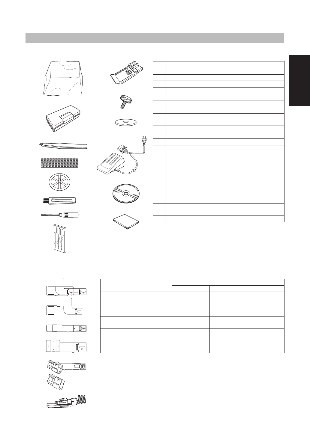
Included accessory
Accessories (Cover stitch model)
1
2
3
4
5
6
7
8
9
0
A
B
C
D
No. Part Name Part Code
1
Soft cover XB3264001
2
Accessory box XB3291001
3
Tweezers XB1618001
4
Thread net (4) X75904000
5
Thread spool cap (4) X77260000
6
Cleaning brush X75906001
7
Hexagonal driver XB0393001
Needle set (130/705H)
8
#90: 3 pcs.
9
Clear foot XB3361001
0
Attachment screw (2) XB3292001
A
Spool mat (4) XB1218001
B
Foot controller
C
Instruction DVD
D
Operation Manual -
XB1216001
XC7359021 (120V Area)
XB3112001 (230V Area)
XB3134001 (U.K.)
XB3200001 (Argentina)
XB3156001 (Korea)
XB3255001 (China)
XB3190001
(Australia, New Zealand)
XF2826001 (Brazil 127V)
XB3178001 (Brazil 220V)
XB3301001 (NTSC)
XB3305001 (PAL)
English
Optional accessory
When using the following accessories, use the presser foot included in the accessories.
E
F
G
H
I
No. Product Name
E
Hemming set SA221CV
F
Bias tape folder SA222CV
G
Belt loop guide SA223CV
H
Bias tape binding set SA230CV
I
Dual function fold binder SA231CV
Americas Europe Others
Part Code
SA221CV/
XB2970-101
SA222CV/
XB2971-101
SA223CV/
XB2972-101
SA230CV/
XB3387-001
SA231CV/
XB3388-001
SA221CV
SA222CV
SA223CV
SA230CVAP
SA231CVAP
5
Page 8
Machine (Top cover stitch model) (Product code: 884-B31)
P
a
b
c
d
e
k
l
m
n
o
p
f
g
h
j
i
Inside of the front cover
U
V
<C>
<B>
W
Thread tree
1
Presser foot pressure adjustment screw
2
Thread take-up cover
3
Thread cutter
4
Material plate cover
5
Needles
6
Bed extension
7
Presser foot
8
Top cover spreader
9
Top cover thread guide
0
Left needle thread tension dial
A
Center needle thread tension dial
B
Right needle thread tension dial
C
Top cover thread tension dial
D
Looper thread tension dial
E
Presser foot lever
F
Front cover
G
Thread guide
H
Spool pin
I
<A>
T
H
q
S
I
J
K
L
M
N
O
Spool cushion
J
Spool support
K
Stitch length adjustment dial
L
Differential feed ratio adjustment dial
M
Handwheel
N
Main power and light switch
O
Foot controller socket
P
Handle
Q
Air openings
R
Q
R
Inside of the front cover
Looper thread tension adjustment lever
S
Looper thread take-up
t
Looper
U
Looper release lever
V
Front cover compartment
W
You can store the included accessories in this
front cover compartment. <A>: Needle set, <B>:
Tweezers, <C>: Hexagonal driver
6
Page 9

Accessories (Top cover stitch model)
Included accessory
1
2
3
4
5
6
7
8
9
0
A
B
C
D
E
No. Part Name Part Code
1
Soft cover XB3264001
2
Accessory box XB3291001
3
Tweezers XB1618001
4
Thread net (5) X75904000
5
Thread spool cap (5) X77260000
6
Cleaning brush X75906001
7
Hexagonal driver XB0393001
Needle set (130/705H)
8
#90: 3 pcs.
9
Clear foot XB3361001
0
Top cover spreader XB3090001
A
Top cover thread guide XB3105001
B
Attachment screw (2) XB3292001
C
Spool mat (5) XB1218001
D
Foot controller
E
Instruction DVD
F
Operation Manual -
XB1216001
XC7359021 (120V Area)
XB3112001 (230V Area)
XB3134001 (U.K.)
XB3200001 (Argentina)
XB3156001 (Korea)
XB3255001 (China)
XB3190001
(Australia, New Zealand)
XF2826001 (Brazil 127V)
XB3178001 (Brazil 220V)
XB3301001 (NTSC)
XB3305001 (PAL)
English
F
Optional accessory
When using the following accessories, use the presser foot included in the accessories.
G
H
I
J
K
No. Product Name
G
Hemming set * SA221CV
H
Bias tape folder SA222CV
I
Belt loop guide SA223CV
J
Bias tape binding set SA230CV
K
Dual function fold binder SA231CV
Americas Europe Others
* Can be used only with a cover stitch; cannot be used with a top cover stitch.
Part Code
SA221CV/
XB2970-101
SA222CV/
XB2971-101
SA223CV/
XB2972-101
SA230CV/
XB3387-001
SA231CV/
XB3388-001
SA221CV
SA222CV
SA223CV
SA230CVAP
SA231CVAP
7
Page 10
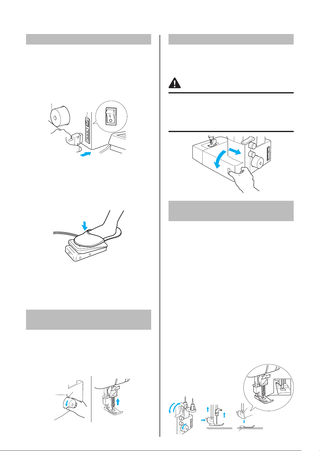
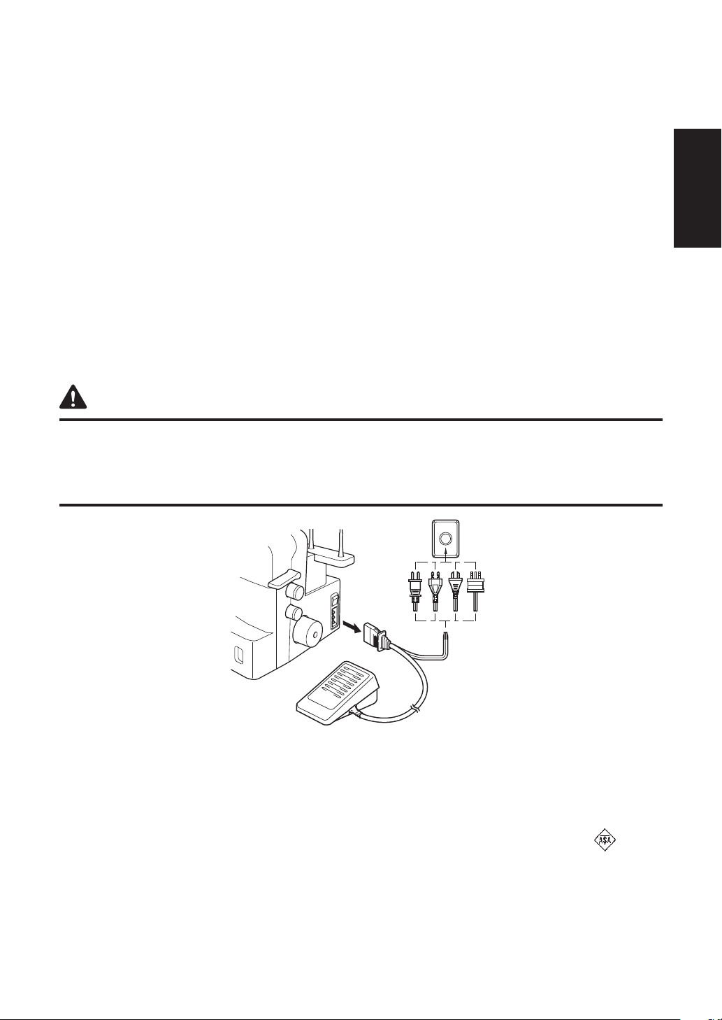
Powering the machine
Turning on the machine
1. Insert the three-pin plug into the socket on the
lower-right side of the machine. Insert the power
supply plug into a power outlet.
2. Turn the main power and light switch <A> to “I”
mark (to “O” mark to turn off).
<A>
Opening/Closing front cover
It is necessary to open the front cover when
threading this machine. Slide it to the right 1, and
then open it 2. After closing it, slide it to the left.
CAUTION
For your safety, make sure that the front cover is
closed when operating the machine.
Always turn off the machine before opening the
front cover.
a
Operation
When the foot controller is pressed lightly, the
machine runs at a low speed. As the foot controller
is pressed further, the machine will increase
speed. When the foot controller is released, the
machine stops.
NOTE (For U.S.A. only):
Foot controller: Model KD-1902
This foot controller can be used on the machine
with product code 884-B30 and 884-B31.
* The product code is shown on the machine rating
plate.
Turning direction of
handwheel
The handwheel <A> turns in a counterclockwise
direction (direction of arrow). This is the same
direction as an ordinary home sewing machine.
Move the needles to their highest positions by
turning the handwheel so that the mark <B> on the
handwheel is aligned with the line on the machine.
b
Attaching/Removing a
presser foot
1. Turn off the main power and light switch or
disconnect the power supply plug.
2. Raise the presser foot lever 1.
3. Turn the handwheel 2 so that the line on
the handwheel is aligned with the line on the
machine. (See “Turning direction of handwheel”
in CHAPTER 1.)
4.
Push the button on the presser foot holder 3 to
release the standard presser foot.
5. Raise the presser foot farther by pushing the
presser foot lever upward. Then, remove the
presser foot and store it in a safe location.
6. Again, raise the presser foot farther by pushing
the presser foot lever upward. Place the presser
foot just under the presser foot holder <A> so
that the groove in the bottom of the presser foot
holder <B> is aligned with the bar on the top of
the foot <C>, and then lower the presser foot
lever to attach the foot 4.
<B>
<A>
d
a
b
a
c
b
<A>
<B>
d
<C>
8
Page 11
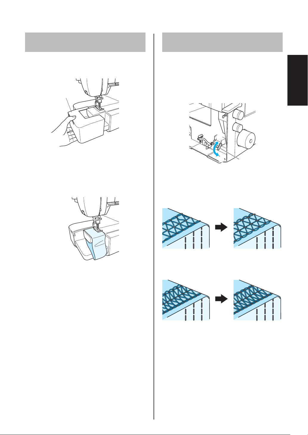
Free-arm sewing
(removing the bed extension)
Free-arm sewing enables tubular pieces to be
sewn more easily.
1. Remove the bed extension.
1
Bed extension
1
NOTE:
Be careful not to lose the removed bed
extension.
2. Position the fabric, and then start sewing.
(See CHAPTER 5.)
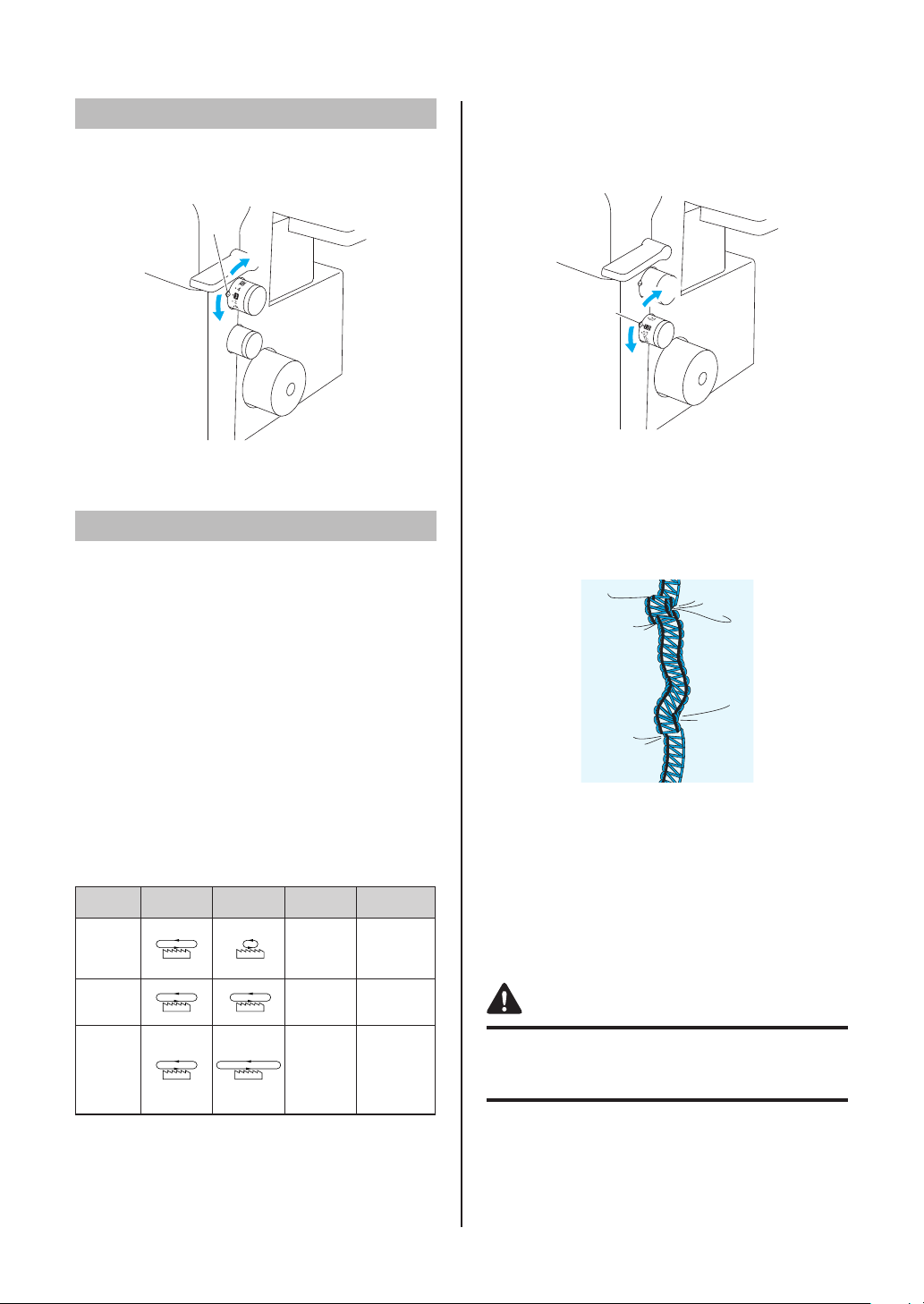
Looper thread tension
adjustment lever
With the looper thread tension adjustment lever,
fi ne adjustments can be made to the looper thread
tension. When sewing stretch fabric or with a small
stitch length, raise the lever to increase the tension
of the looper thread. When sewing non-stretch
fabric or with a large stitch length, lower the lever
to reduce the tension of the looper thread.
1
2
Raise the lever to increase the tension of the looper thread.
1
Lower the lever to reduce the tension of the looper thread.
2
<A> Looper thread tension adjustment lever
Non-stretch fabric such as serge
Reduce the tension of the looper thread.
<A>
English
Lever position: Center Lever position: Down
Stretch fabric such as smooth knit
Increase the tension of the looper thread.
Lever position: Center Lever position: Up
9
Page 12
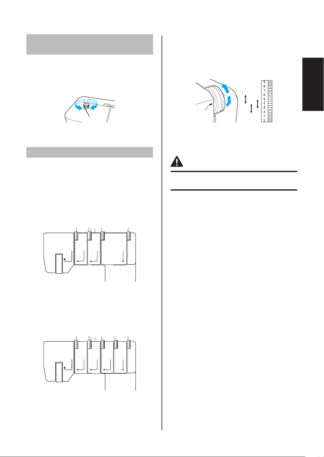
Stitch length
The normal stitch length setting is 3 mm. To
change the stitch length, turn the stitch length
adjustment dial on the right side of the machine.
<A>
a
b
Shorten the stitch length to a minimum of 2 mm (5/64 inch).
1
Lengthen the stitch to a maximum of 4 mm (5/32 inch).
2
<A> Selection mark
The normal setting is 1.0 on the differential feed
adjustment dial.
To adjust the differential feed, turn the dial on the
lower-right side of the machine.
a
<A>
b
Less than 1.0
1
Greater than 1.0
2
<A> Selection mark
Differential feed
There are two sets of feed dogs under the presser
foot to move the fabric through the machine. The
differential feed controls the movement of both the
front and the rear feed dogs. When set at 1, the
feed dogs are moving at the same speed (ratio of 1).
When the differential feed ratio is set at less than
1, the front feed dogs move less than the rear
feed dogs, stretching the fabric as it is sewn. This
is effective on lightweight fabric that may pucker.
When the differential feed ratio is set at greater
than 1, the front feed dogs move more than the
rear feed dogs, gathering the fabric as it is sewn.
This function assists in removing rippling when
sewing stretch fabrics.
Differential feed adjustment
Feed ratio Main feed
(rear)
Less than
1.0
1.0
Greater
than 1.0
Differential
feed (front)
Effect Application
Material is
pulled tight.
Without
differential
feed.
Material is
gathered
or pushed
together.
Prevents thin
materials
from
puckering
Normal
sewing
Prevents
stretch
materials
from
stretching or
puckering
An example
When stretch material is sewn without using the
differential feed, the fabric will be wavy.
To get a smooth fi nish, adjust the feed ratio from 1.0
toward 2.0.
(The feed ratio required depends on the elasticity
of the material.)
The more elastic the material, the further toward
2.0 the differential feed ratio should be set. Test
sew with a scrap of the fabric to fi nd the correct
adjustment.
CAUTION
When sewing thick non-stretchable material such
as denim, do not use the differential feed as it may
damage the fabric.
10
Page 13
Adjusting the presser
foot pressure
Turn the pressure adjustment screw on the left of
the top of the machine. Refer to the value on the
screw to make the adjustment.
The normal setting is “2”.
ab
<A>
Less pressure
1
More pressure
2
<A> Selection mark
Adjusting the tension dials
There is a thread tension dial for each needle
thread, the looper thread and the top cover thread.
The correct thread tension may vary according to
the type and thickness of the fabric and the type of
thread used. Thread tension adjustments may be
necessary for any change in sewing materials.
Cover stitch model
Tension control
Sewing is possible at position “4” for most
circumstances. (Standard: SPAN #60)
If the stitch quality is insuffi cient, select a different
tension setting.
5
4
3
1
3
2
<A>
For heavy tension: 4 to 6
1
For light tension: 4 to 2
2
For medium tension: 5 to 3
3
<A> Tension selection mark
CAUTION
Make sure that the thread is properly seated in the
tension discs.
English
123
The tension dial marked in yellow is for the left needle thread.
1
The tension dial marked in green is for the center needle
2
thread.
The tension dial marked in pink is for the right needle thread.
3
The tension dial marked in blue is for the looper thread.
4
4
4444
Top cover stitch model
1234
The tension dial marked in yellow is for the left needle thread.
1
The tension dial marked in green is for the center needle
2
thread.
The tension dial marked in pink is for the right needle thread.
3
The tension dial marked in purple is for the top cover thread.
4
The tension dial marked in blue is for the looper thread.
5
5
4
4444
11
Page 14
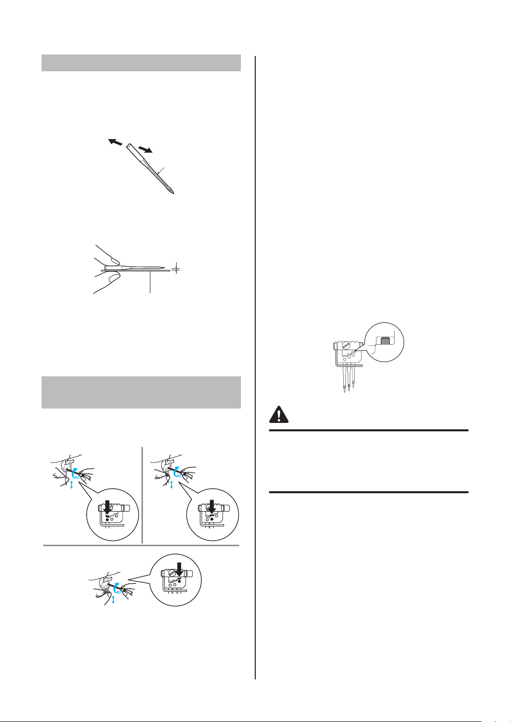
Needle
This machine uses a standard home sewing
machine needle.
The recommended needle is 130/705H (#90).
Needle description
1
Back (fl at side)
1
Front
2
Groove
3
How to check the needle
Flat surface
4
Place the needle on its fl at side and check to see if the space
5
is even.
NOTE:
Fabric damage can be reduced by using 130/705H
SUK (#90) BALL POINT.
2
3
5
4
To remove:
1. Turn off the main power and light switch.
2. Turn the handwheel so that the line on the
handwheel is aligned with the line on the
machine. (See “Turning direction of handwheel”
in CHAPTER 1.)
3. Loosen the corresponding needle set screw
by turning it with the included hexagonal driver
toward 2 in the illustration, and then remove
the needle.
To install:
1. Turn off the main power and light switch.
2. Turn the handwheel so that the line on the
handwheel is aligned with the line on the
machine.
3. Hold the needle with its fl at side away from you
and insert it up as far as it will go.
4. Tighten the needle set screw securely by
turning it with turning the included hexagonal
driver toward 1 in the illustration.
NOTE:
Be sure to insert the needles all the way.
Removing/Installing
the needle
<A> Removing/installing the left needle
<B> Removing/installing the center needle
<C> Removing/installing the right needle
<A>
Tighten
1
Loosen
2
1
2
<C>
1
2
<B>
CAUTION
Always be sure to turn off the power before
removing/inserting the needle.
1
2
Do not drop the needle and needle set screw in
the machine, otherwise it may be damaged.
12
Page 15
CHAPTER 2
PREPARATION BEFORE THREADING
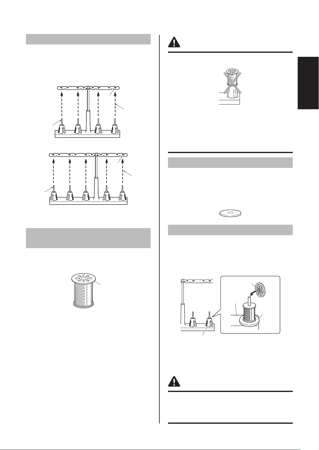
Thread tree
Raise the telescoping thread tree to its highest
position. Make sure that the thread holders are
in alignment above the spool pins as illustrated
below.
Cover stitch model
1
3
2
Top cover stitch model
1
3
2
Thread holder on thread tree
1
Spool pin
2
Correct position
3
CAUTION
Before using a thread spool, be sure to remove the
spool cushion.
English
Before using loosely spun nylon thread, be sure to
install the spool cushion.
If the thread spool cap is not fully pushed down,
the thread may become entangled on the spool pin
or the needle may bend or break.
Spool mat
When using thread spools or loosely spun thread
that easily slips off the spool, place this mat under
the spool.
This prevents the thread from becoming entangled
on the spool pin.
Using the thread
spool cap
When using sewing thread spools, the thread
spool cap should be used as illustrated below.
Make sure that the spool notch is on the bottom.
1
Thread spool cap
1
Using the spool mat
1. Remove the spool cushion, and then place the
spool mat on the spool pin.
2. Place the thread spool (with the spool notch at
the bottom) on the spool pin, and then place the
thread spool cap on top and fully push it down.
2
3
4
1
Spool cushion
1
Thread spool cap
2
Spool support
3
Spool mat
4
CAUTION
If the thread spool cap is not fully pushed down
against the thread spool, the thread may become
entangled on the spool pin or the needle may bend
or break.
13
Page 16
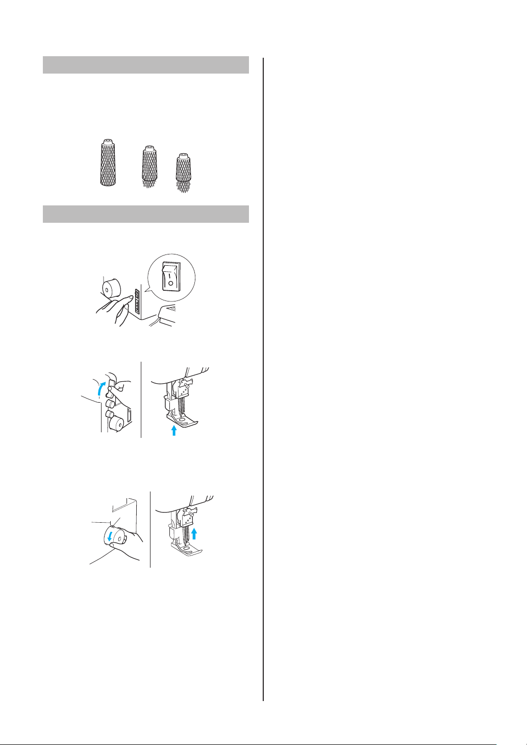
Using the thread net
If you are sewing with loosely spun nylon thread,
we recommend that you cover the spool with the
included net in order to prevent the thread from
slipping off the spool.
Adapt the net to the shape of the spool.
Before threading
1. Turn off the main power and light switch for
safety.
2. Raise the presser foot using the presser foot
lever.
3. Turn the handwheel so that the line on the
handwheel <A> is aligned with the line <B>
on the machine. (See “Turning direction of
handwheel” in CHAPTER 1.)
<B>
<A>
14
Page 17
CHAPTER 3
THREADING (Cover stitch model)
1. Open the front cover by sliding it to the right and
CAUTION
Before threading, turn off the machine for safety.
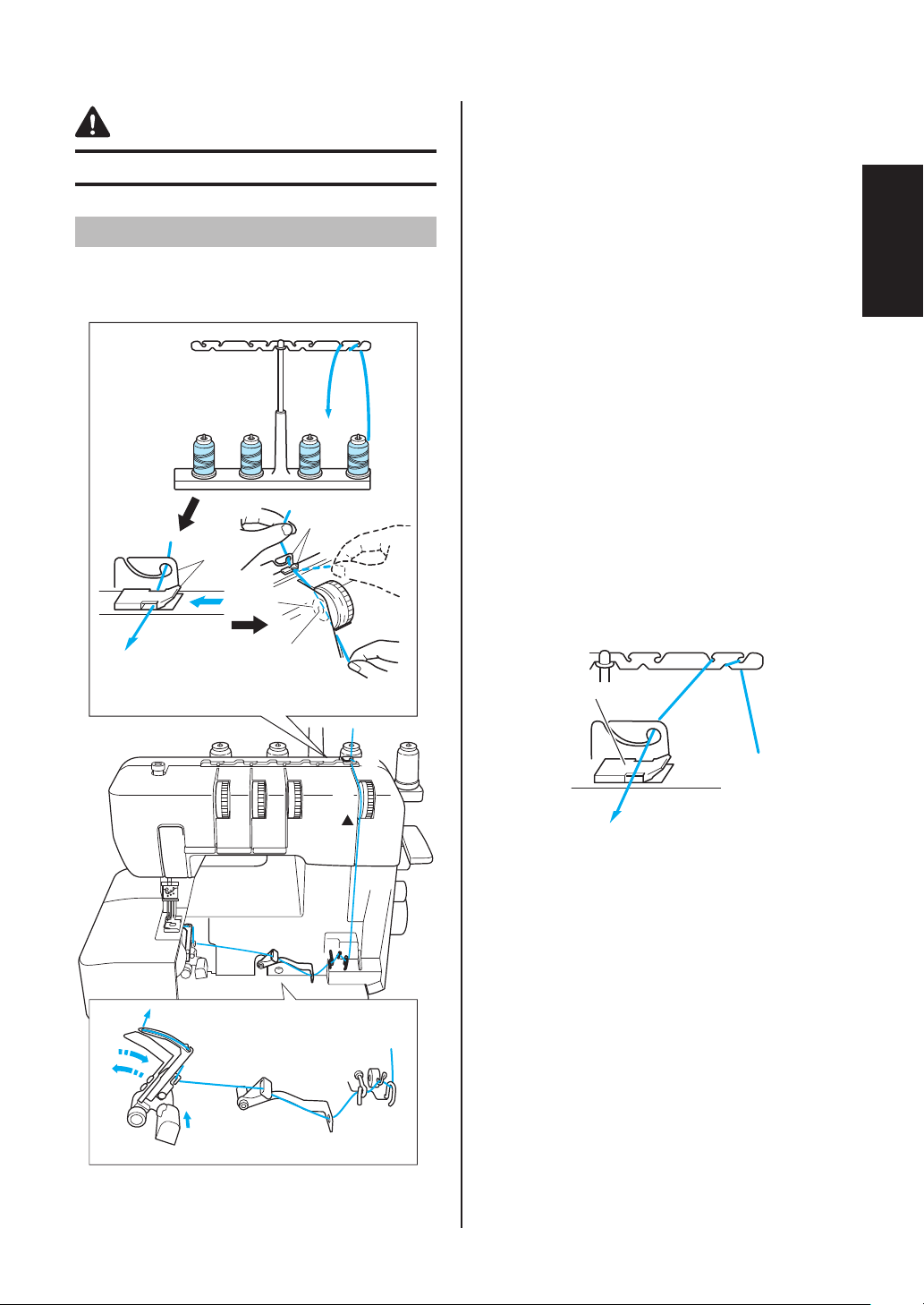
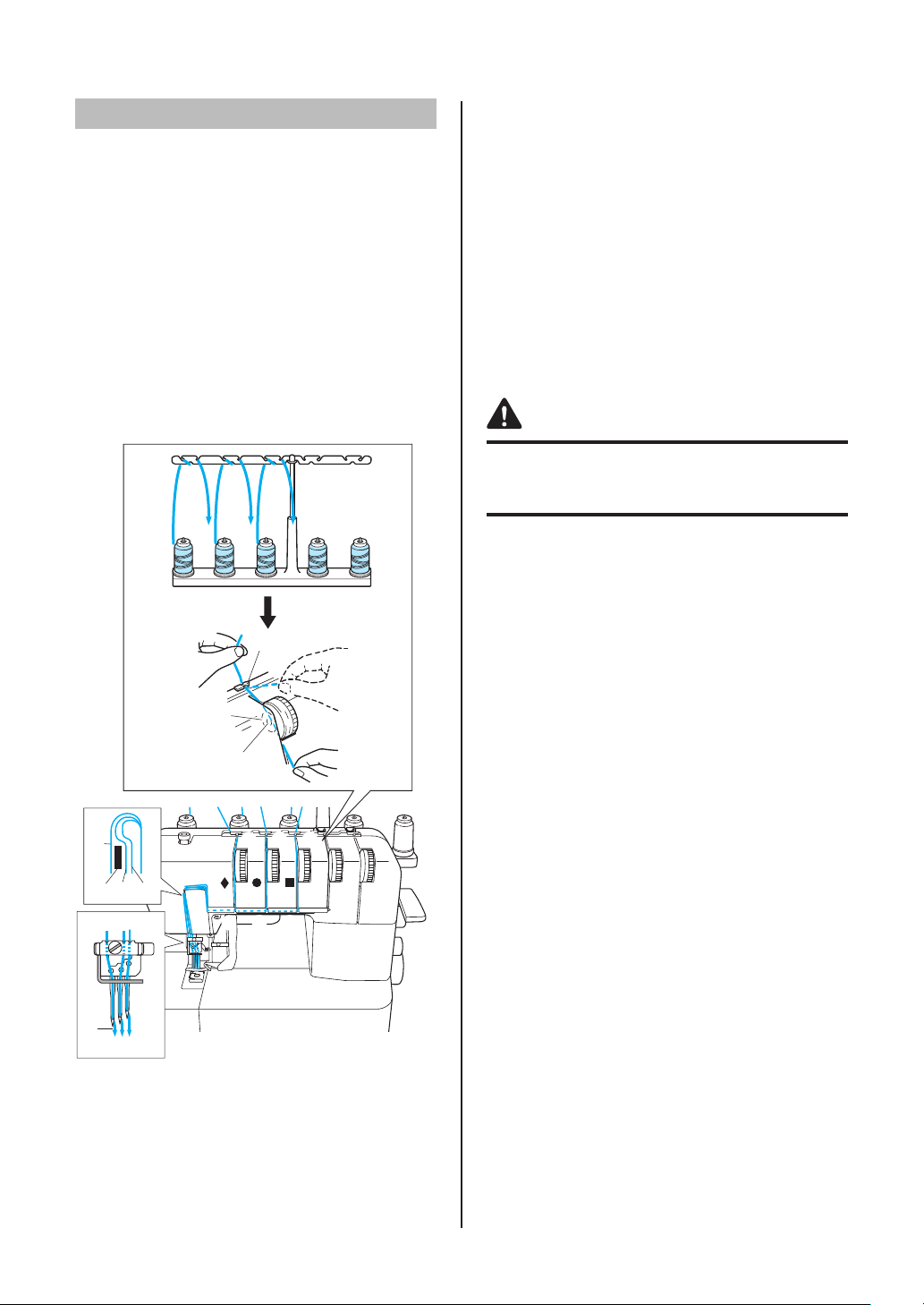
Threading the looper
Run the thread in the sequence illustrated,
following the blue line and the numbers next to
each threading point.
2
1
3
3
6
A
4
5
4
guiding the top toward you.
2. Pull the thread off the spool and directly up
through thread holder 1 and thread holder 2
on the thread tree, from back to front.
3. Pass the looper thread 3 as shown in the
illustration.
4. Pass the thread through the tension disc 4 in
the channel next to the tension dial marked with
a blue c.
5. Guide the thread down the channel and through
threading points 5-9, following the numerical
order in the illustration.
6. After running the thread to 9, push the looper
release lever 0 to move the looper to the right A,
and then run the thread through B-C.
7. Pull about 10 cm (4 inch) of thread through the
eye of the looper.
8. While pushing the looper D, return the looper
to its original position.
9. Close the front cover.
NOTE:
When using thick thread, such as decorative
thread, as the looper thread, run the thread as
shown in the illustration.
English
A
D
C
:
B
9
8
A
3
4
Do not run the thread through A.
6
5
7
15
Page 18
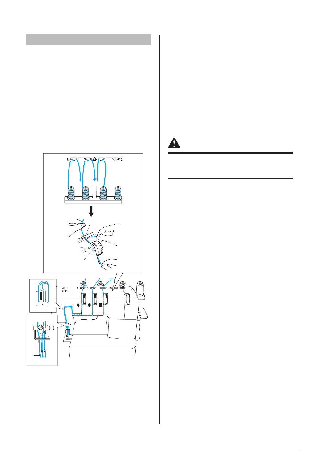
Threading the needles
Needle threads used by the various
stitches
The triple cover stitch (three-needle, four-thread
cover stitch) uses the left needle thread, center
needle thread and right needle thread.
The two-needle, three-thread cover stitch (Wide) (6
mm (15/64 inch)) uses the left needle thread and
right needle thread.
The two-needle, three-thread cover stitch (Narrow)
(3 mm (1/8 inch)) uses the center needle thread
and right needle thread.
The chain stitch uses the center needle thread
and looper thread.
212
2
1
F
444
333
6
5
1
4
Threading the left needle
Run the thread in the sequence illustrated,
following the yellow numbers and ¡ marks next to
the threading points. (1-9)
Threading the center needle
Run the thread in the sequence illustrated,
following the green numbers and z marks next to
the threading points. (1-9)
Threading the right needle
Run the thread in the sequence illustrated,
following the pink numbers and marks next to
the threading points. (1-9)
CAUTION
When threading the needles, always thread in the
following order: left needle, center needle and right
needle.
1. Pull the thread off the spool and directly up
through thread holder
on the thread tree, from back to front.
222
2. Pass each thread through
illustration.
3. Pass the thread through the tension disc
in the channel next to the tension dial.
4. Guide the thread down the channel and across
through threading points
the color marks, following the numerical order in
the illustration.
5. Pass the thread through the eye of the needle,
front to back.
and thread holder
111
333
555-888
, shown in the
444
next to
A
DB
7
8
666
C
77
88
4
5
3
4
5
4
5
3
3
E
9
99
To left needle
A
To center needle
B
To right needle
C
Branching plate
D
Pull about 6 cm (about 2-1/2 inches) of thread through the
E
eye of the needle.
999
Front to back
16
Page 19
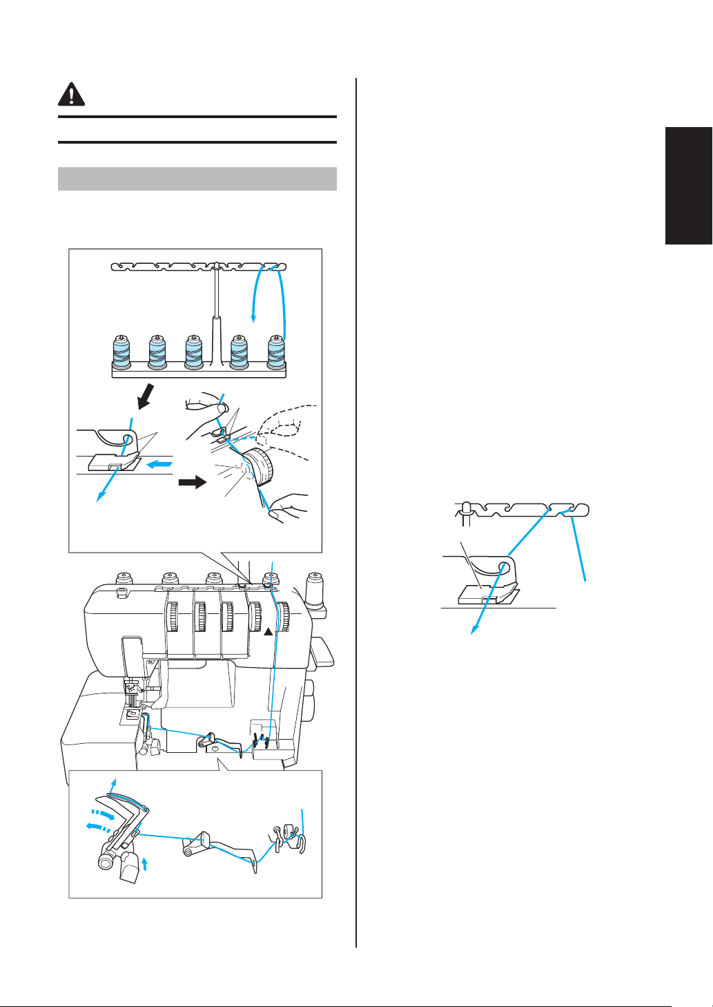
CHAPTER 4
THREADING (Top cover stitch model)
1. Open the front cover by sliding it to the right and
CAUTION
Before threading, turn off the machine for safety.
Threading the looper
Run the thread in the sequence illustrated,
following the blue line and the numbers next to
each threading point.
2
1
3
3
6
A
4
5
4
guiding the top toward you.
2. Pull the thread off the spool and directly up
through thread holder 1 and thread holder 2
on the thread tree, from back to front.
3. Pass the looper thread 3 as shown in the
illustration.
4. Pass the thread through the tension disc 4 in
the channel next to the tension dial marked with
a blue c.
5. Guide the thread down the channel and through
threading points 5-9, following the numerical
order in the illustration.
6. After running the thread to 9, push the looper
release lever 0 to move the looper to the right A,
and then run the thread through B-C.
7. Pull about 10 cm (4 inch) of thread through the
eye of the looper.
8. While pushing the looper D, return the looper
to its original position.
9. Close the front cover.
NOTE:
When using thick thread, such as decorative
thread, as the looper thread, run the thread as
shown in the illustration.
English
A
D
C
:
B
9
8
A
3
4
Do not run the thread through A.
6
5
7
17
Page 20
Threading the needles
Needle threads used by the various
stitches
The triple cover stitch (three-needle, four-thread
cover stitch) uses the left needle thread, center
needle thread and right needle thread.
The two-needle, three-thread cover stitch (Wide) (6
mm (15/64 inch)) uses the left needle thread and
right needle thread.
The two-needle, three-thread cover stitch (Narrow)
(3 mm (1/8 inch)) uses the center needle thread
and right needle thread.
The chain stitch uses the center needle thread and
looper thread.
212
2
1
444
F
1
333
6
5
4
Threading the left needle
Run the thread in the sequence illustrated,
following the yellow numbers and ¡ marks next to
the threading points. (1-9)
Threading the center needle
Run the thread in the sequence illustrated,
following the green numbers and z marks next to
the threading points. (1-9)
Threading the right needle
Run the thread in the sequence illustrated,
following the pink numbers and marks next to
the threading points. (1-9)
CAUTION
When threading the needles, always thread in the
following order: left needle, center needle and right
needle.
1. Pull the thread off the spool and directly up
through thread holder
on the thread tree, from back to front.
222
2. Pass each thread through
illustration.
3. Pass the thread through the tension disc
in the channel next to the tension dial.
4. Guide the thread down the channel and across
through threading points
the color marks, following the numerical order in
the illustration.
5. Pass the thread through the eye of the needle,
front to back.
and thread holder
111
333
555-888
, shown in the
444
next to
A
DB
7
8
666
C
77
88
4
5
3
4
5
4
5
3
3
E
9
99
To left needle
A
To center needle
B
To right needle
C
Branching plate
D
Pull about 6 cm (about 2-1/2 inches) of thread through the
E
eye of the needle.
999
Front to back
18
Page 21
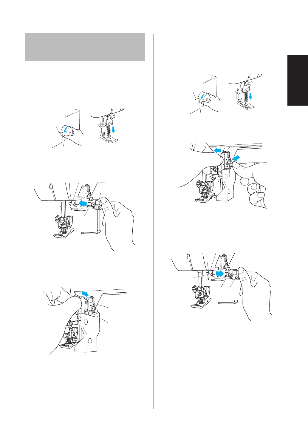
Attaching/Removing
the top cover spreader and
top cover thread guide
Attaching the top cover spreader and
top cover thread guide
1. Turn the handwheel so that the line on the
handwheel <A> is aligned with the line <B> on
the machine.
<B>
<A>
2. Squeeze the grip of the top cover spreader to
spread the tips, and then, from the right side,
clamp the mount of the top cover spreader onto
the top cover drive shaft.
1
Removing the top cover spreader and
top cover thread guide
1. Turn the handwheel so that the line on the
handwheel is aligned with the line on the
machine.
<B>
<A>
2. Press the lever on the top cover thread guide
mount, and then remove the top cover thread
guide.
1
2
English
3
2
Grip of top cover spreader
1
Mount of top cover spreader
2
Top cover drive shaft
3
3. Insert the top cover thread guide into the slot in
the top cover thread guide mount.
5
4
Top cover thread guide
4
Slot
5
Lever
1
Top cover thread guide
2
3. Squeeze the grip of the top cover spreader to
spread the tips, and then remove the mount of
the top cover spreader from the top cover drive
shaft.
5
4
3
Grip of top cover spreader
3
Mount of top cover spreader
4
Top cover drive shaft
5
19
Page 22

Threading the top cover
spreader
NOTE:
Thread the top cover thread after fi rst sewing a
cover stitch seam.
Needle threads used by the various
stitches
The triple top cover stitch (three-needle, fi vethread) uses the left needle thread, center needle
thread and right needle thread.
The top cover two-needle, three-thread cover
stitch (Wide) (6 mm (15/64 inch)) uses the left
needle thread and right needle thread.
The top cover two-needle, three-thread cover
stitch (Narrow) (3 mm (1/8 inch)) uses the center
needle thread and right needle thread.
Run the thread in the sequence illustrated,
following the purple color and the numbers next to
each threading point.
2
1. Pull the thread off the spool and directly up
through thread holder 1 and thread holder 2
on the thread tree, from back to front.
2. Pass each thread through 3, shown in the
illustration.
3. Pass the thread through the tension disc 4 in
the channel next to the tension dial marked with
a purple .
4. Guide the thread down the channel and across
through threading points 5-9 next to the color
marks, following the numerical order in the
illustration.
5. Turn the handwheel counterclockwise to move
the point of the top cover spreader completely
to the left.
6. Thread the point of the top cover spreader as
shown in the illustration 0.
1
7. Pass the top cover thread under the presser
foot, from left to right, as shown in the
illustration A, and then lower the presser foot.
3
3
6
F
5
4
4
8. Turn the handwheel counterclockwise 2 to 3
times to check that the top cover thread forms
stitches.
3
4
6
5
NOTE:
When using thick thread, such as decorative
thread, as the top cover thread, run the thread as
shown in the illustration.
A
7
8
9
0
A
Do not run the thread through A.
20
Page 23

CHAPTER 5
TYPE OF STITCHES COMPARISON CHART
Type of
stitch
Triple
cover
stitch
Cover
stitch
(Wide)
Cover
stitch
(Narrow)
Chain
stitch
Triple top
cover
stitch
Top cover
stitch
(Wide)
Top cover
stitch
(Narrow)
Number
of needles
Number
of threads
3 4 2-5 2-5 2-5 2-5
2 3 3-5 - 3-5 2-5
2 3 - 3-5 3-5 2-5
1 2 - 2-5 - 2-5
3 5 3-5 3-5 3-5 3-5 3-5
2 4 3-5 - 3-5 3-5 3-5
2 4 - 3-5 3-5 3-5 3-5
Left
needle
Thread tension dial
Center
needle
Right
needle
Top cover
thread*
Looper
thread
Stitch
Model
Cover
stitch
Top cover
stitch
33
33
33
33
3
3
3
* Top cover stitch model only.
NOTE:
The thread tension dial settings listed above are based on a stitch length of 3 and a differential feed ratio of 1.0.
Since the settings may differ depending on the types of fabric and thread used, be sure to check the thread
tension.
English
Triple cover stitch
Balanced tension
The needle thread sews a straight seam on the
surface of the fabric, and the looper thread forms
loops on the back.
Stitching direction
Needle thread is too loose.
Turn the needle thread tension dial to a higher
number to increase the tension, or turn the looper
thread tension dial to a lower number to decrease the
tension.
Needle thread is too tight.
Turn the needle thread tension dial to a lower number
to decrease the tension, or turn the looper thread
tension dial to a higher number to increase the
tension.
21
Page 24

Cover stitch (Wide/Narrow)
Stitching direction
Chain stitch
Stitching direction
Balanced tension
The needle thread sews a straight seam on the
surface of the fabric, and the looper thread forms
loops on the back.
Needle thread is too loose.
Turn the needle thread tension dial to a higher
number to increase the tension, or turn the looper
thread tension dial to a lower number to decrease the
tension.
Needle thread is too tight.
Turn the needle thread tension dial to a lower number
to decrease the tension, or turn the looper thread
tension dial to a higher number to increase the
tension.
22
Page 25

Triple top cover stitch
Balanced tension
The top cover thread sews a straight seam on the
surface of the fabric, and the looper thread forms
loops on the back.
Stitching direction
Top cover stitch (Wide/Narrow)
Stitching direction
Top cover thread is too loose.
Turn the top cover thread tension dial to a higher
number to increase the tension, or turn the needle
thread tension dial to a lower number to reduce the
tension.
Top cover thread is too tight.
Turn the top cover thread tension dial to a lower
number to decrease the tension, or turn the needle
thread tension dial to a higher number to increase the
tension.
Balanced tension
The top cover thread sews a straight seam on the
surface of the fabric, and the looper thread forms
loops on the back.
Top cover thread is too loose.
Turn the top cover thread tension dial to a higher
number to increase the tension, or turn the needle
thread tension dial to a lower number to reduce the
tension.
English
Top cover thread is too tight.
Turn the top cover thread tension dial to a lower
number to decrease the tension, or turn the needle
thread tension dial to a higher number to increase the
tension.
23
Page 26

CHAPTER 6
SEWING
CAUTION
While the machine is in operation, pay special
attention to the needle location. In addition, keep
your hands away from all moving parts such as
the needle and handwheel, otherwise injuries may
occur.
Sewing fl at fabric
(for example, trial sewing)
1. Raise the presser foot, and then place the
fabric at the needle drop position.
NOTE:
When sewing stretch fabrics, adjust the
differential feed and check that the desired
fi nish is achieved.
Removing the fabric
from the machine
(Cover stitch model)
1. By hand, turn the handwheel toward you until
the needle is at its highest position.
2. Raise the presser foot.
2. Lower the presser foot, turn the handwheel
toward you a few times by hand, and then
lightly step on the foot controller to start sewing.
NOTE:
When starting to sew or after changing the
thread, in order for the needle thread to be on
top of the presser foot, sew with it positioned
under the presser foot when you begin sewing.
If necessary, turn the handwheel toward you a
few times by hand, and then cut the thread as
shown in the illustration.
3. Slowly pull the fabric in the direction of the
arrow.
NOTE:
Be sure to pull the fabric to the back.
4. Cut the needle threads, which come out from
the surface of the fabric.
24
Page 27

5. Slowly pull the fabric in the direction of the
arrow so that the ends of the needle threads
are pulled to the back of fabric.
6. Cut the looper thread.
Removing the fabric
from the machine
(Top cover stitch model)
1. By hand, turn the handwheel toward you until
the needle is at its highest position.
English
2. Raise the presser foot.
3. Slowly pull the fabric in the direction of the
arrow.
NOTE:
Be sure to pull the fabric to the back.
NOTE:
We recommend using scissors to cut the looper
thread. Scissors can also be used to cut the
machine threads.
7. Pull all threads at the back of the fabric.
Tie all threads together and cut.
4. Cut the needle threads, which come out from
the surface of the fabric.
25
Page 28

5. Slowly pull the fabric in the direction of the
arrow so that the ends of the needle threads
are pulled to the back of fabric.
6. Cut the looper thread.
7. Use a pointed object, such as a needle, to push
in the top cover thread from the surface of the
fabric, and then pull the thread at the back of
the fabric.
8. Pull all threads at the back of the fabric.
Tie all threads together and cut.
NOTE:
We recommend using scissors to cut the looper
thread. Scissors can also be used to cut the
machine threads.
26
Page 29

Sewing a cover stitch
1. Determine how much of the fabric will be folded
up.
2. Fold up the fabric the desired amount, and then
iron it in place.
3. Use a ruler to measure, and then use a
fabric marker to mark the top of the fabric to
sew where the edge of the folded fabric is
positioned.
4. Place the bottom of the presser foot onto the
top of fabric, and then check that the drawn
mark is just barely to the right of the left needle.
5. Sew exactly on the mark.
6. After sewing is fi nished, refer to “Removing the
fabric from the machine (Cover stitch model)”
on page 24 for details on taking care of the
threads.
2
3
1
4
Sewing tubular garments
(for example, cuffs)
Without free-arm sewing
1. Raise the presser foot, insert the fabric as
shown in the illustration, lower the presser foot,
and then begin sewing.
English
2. Finish sewing by overlapping about 4 cm (1-1/2
inch) of the beginning and end of the stitching.
6
5
Fabric (surface)
1
Mark drawn with fabric marker
2
Left needle (just barely on the left side of the mark)
3
Right needle
4
Fabric
5
Needle
6
NOTE:
When sewing tubular garments, overlapping
the beginning and end of the stitching by about
4 cm (1-1/2 inch) will prevent the seam from
tearing.
3. Remove the fabric as explained in “Removing
the fabric from the machine (Cover stitch model)”
and “Removing the fabric from the machine (Top
cover stitch model)” on pages 24 and 25.
27
Page 30

With free-arm sewing
1. Remove the bed extension.
1
Bed extension
1
2. Position the fabric, and start sewing.
(See CHAPTER 5.)
Stabilizing the beginning and
end of stitching
To sew with the beginning and end of stitching
stabilized, fi nish the beginning and end of stitching
with a 4-cm-square piece of scrap fabric as
described below.
Beginning of stitching
1. Raise the presser foot, and then insert the
scrap fabric. Lower the presser foot, turn the
handwheel toward you a few times by hand,
and then lightly step on the foot controller to
start sewing.
2. When nearing the end of stitching for the scrap
fabric, stop the machine. Insert the fabric as
shown in the illustration below, and then lightly
step on the foot controller to start sewing.
a
b
(1) Raise the presser foot, insert the fabric as
shown in the illustration, lower the presser foot,
and then begin sewing.
(2) Finish sewing by overlapping about 4 cm
(1-1/2 inch) of the beginning and end of the
stitching.
Scrap fabric
1
Fabric
2
End of stitching
1. When nearing the end of stitching for the fabric,
stop sewing. Insert the scrap fabric as shown in
the illustration below, and then fi nish sewing.
2. Sew into the scrap fabric, stop the machine, and
then use scissors to cut the threads between
the fabrics and scrap fabrics.
28
Page 31

CHAPTER 7
TROUBLESHOOTING
This sewing machine is designed for trouble-free operation. However, the following chart indicates trouble
which may occur if basic adjustments are not made properly.
Trouble Cause Remedy
1. Does not feed Presser foot pressure too loose Turn the pressure adjustment
screw clockwise to increase the
presser foot pressure.
(See page 11.)
2. Needles break 1. Needles bent, or needle tip blunt Replace with new needle.
(See page 12.)
2. Needles incorrectly installed Install needles correctly.
(See page 12.)
3. Material pulled forcibly Do not press or pull material too
hard when sewing.
3. Threads break 1. Improper threading Thread correctly.
(See pages 15-18, 20.)
2. Thread tangled Check spool pin, thread holders,
etc., and remove tangled thread.
3. Thread tension too tight Adjust the thread tension.
(See pages 11.)
4. Needles incorrectly installed Install needles correctly.
(See page 12.)
5. Wrong needle used Use correct needle.
130/705H recommended
(See page 12.)
4. Skipped stitches 1. Needle bent, or needle tip blunt Replace with new needle.
(See page 12.)
2. Needle incorrectly installed Install needle correctly.
(See page 12.)
3. Wrong needle used Use correct needle.
130/705H recommended
(See page 12.)
4. Improper threading Thread correctly.
(See pages 15-18, 20.)
5. Presser foot pressure too loose Turn the pressure adjustment
screw clockwise to increase the
presser foot pressure.
(See page 11.)
5. Stitches not uniform Thread tensions not adjusted
properly
6. Fabric puckers 1. Thread tension too tight Decrease thread tension when
2. Improper threading or thread
tangled
Adjust the thread tension.
(See pages 11.)
sewing lightweight or fi ne material.
(See pages 11.)
Thread correctly.
(See pages 15-18, 20.)
English
29
Page 32

CHAPTER 8
MAINTENANCE
Cleaning
CAUTION
Turn off the machine before cleaning.
Turn the handwheel and move the needles down.
Periodically clean out dust, trimmed fabric and
thread with the included cleaning brush.
30
Page 33

SPECIFICATIONS
Cover stitch model
Use Fine to heavy materials
Sewing speed Maximum 1,000 stitches per minute
Stitch width 6 mm / 3 mm
Stitch length (pitch) 2 mm to 4 mm (5/64 to 5/32 inch)
Needle bar stroke 29 mm (1 1/8 inches)
Presser foot Free presser type
Presser foot lift 5 mm to 6 mm (3/16 to 15/64 inch)
Needle SCHMETZ 130/705H (90/#14)
Number of needles and threads Convertible to two/three/four threads
Convertible to one/two/three needles
Stitches One-needle, two-thread double chain stitch
Two-needle, three-thread cover stitch (Wide) (6 mm (15/64inch))
Two-needle, three-thread cover stitch (Narrow) (3 mm (1/8inch))
Three-needle, four-thread triple cover stitch (6 mm (15/64inch))
Machine net weight 7.6 kg
Machine dimensions 396 mm (W) × 297 mm (D) × 358 mm (H)
(Approx. 16 (W) × 12 (D) × 14 (H) inches)
Needle set 130/705H
English
Top cover stitch model
Use Fine to heavy materials
Sewing speed Maximum 1,000 stitches per minute
Stitch width 6 mm / 3 mm
Stitch length (pitch) 2 mm to 4 mm (5/64 to 5/32 inch)
Needle bar stroke 29 mm (1 1/8 inches)
Presser foot Free presser type
Presser foot lift 5 mm to 6 mm (3/16 to 15/64 inch)
Needle SCHMETZ 130/705H (90/#14)
Number of needles and threads Convertible to two/three/four/five threads
Convertible to one/two/three needles
Stitches One-needle, two-thread double chain stitch
Two-needle, three-thread cover stitch (Wide) (6 mm (15/64inch))
Two-needle, three-thread cover stitch (Narrow) (3 mm (1/8inch))
Three-needle, four-thread triple cover stitch (6 mm (15/64inch))
Two-needle, four-thread top cover stitch (Wide) (6 mm (15/64inch))
Two-needle, four-thread top cover stitch (Narrow) (3 mm (1/8inch))
Three-needle, five-thread triple top cover stitch (6 mm (15/64inch))
Machine net weight 7.6 kg
Machine dimensions 396 mm (W) × 297 mm (D) × 358 mm (H)
(Approx. 16 (W) × 12 (D) × 14 (H) inches)
Needle set 130/705H
31
Page 34

INSTRUCCIONES DE SEGURIDAD IMPORTANTES
Cuando utilice la máquina de coser, deben seguirse algunas precauciones básicas de seguridad, como las siguientes.
Lea todas las instrucciones antes de utilizar la máquina.
17. Esta máquina de coser no ha sido diseñada para ser
PELIGRO
Para reducir el riesgo de descarga eléctrica.
La máquina de coser nunca debe dejarse desatendida
mientras esté enchufada. Desconéctela de la toma de
corriente inmediatamente después de su uso y antes
de proceder a su limpieza.
utilizada por niños ni por personas enfermas sin la
supervisión de un adulto.
Los niños pequeños deberán ser vigilados para
18.
asegurarse de que no juegan con esta máquina de coser.
19. No desmonte la máquina.
20. Si la unidad de la luz LED (diodo emisor de luz) está
dañada, deberá cambiarla un distribuidor autorizado.
AVISO
Para reducir el riesgo de quemaduras, incendio,
descarga eléctrica o lesiones.
1. No debe utilizarse como si fuera un juguete. Deberá
prestar especial atención cuando la máquina de coser
se utilice cerca de niños o sea utilizada por ellos.
Utilice esta máquina de coser solo para los fi nes descritos
2.
en este manual. Utilice solo los accesorios recomendados
por el fabricante indicados en este manual.
3. Nunca utilice esta máquina de coser si el cable o el
enchufe están dañados, si no funciona correctamente,
si se ha caído o ha sufrido averías, o si se ha caído
al agua. Lleve la máquina de coser al distribuidor o
centro de reparaciones autorizado más cercano para
su examen, reparación y realización de los ajustes
eléctricos o mecánicos necesarios.
4. Nunca utilice la máquina de coser si las aberturas de
ventilación están bloqueadas. Mantenga las aberturas
de ventilación de la máquina de coser y el pedal libres
de pelusa, polvo y trocitos de tela.
5. Nunca deje que caigan objetos en ninguna de las
aberturas, ni inserte nada en las mismas.
6. No la utilice al aire libre.
7. No la use en lugares donde se utilicen productos con
aerosoles (atomizadores), ni en sitios donde se esté
administrando oxígeno.
Para desconectar, coloque el interruptor principal en
8.
la posición con el símbolo “O” que indica apagado y, a
continuación, desconecte el enchufe de la toma de corriente.
9. No la desenchufe tirando del cable. Para desenchufar,
sujete el enchufe, no el cable.
10. Mantenga los dedos alejados de todas las piezas en
movimiento. Debe tenerse un cuidado especial con el
espacio que rodea a la aguja de la máquina de coser.
Utilice siempre la placa de la aguja correcta. Si utiliza una
11.
placa que no sea la adecuada, la aguja podría romperse.
12. No utilice agujas dobladas.
13. No tire de la tela ni la empuje cuando esté cosiendo.
Podría doblar la aguja y romperla.
Cuando vaya a hacer algún ajuste en la zona de la aguja,
14.
como enhebrarla, cambiarla, cambiar el prensatelas, etc.,
coloque la máquina de coser en la posición con el símbolo “O”.
15. Desenchufe siempre la máquina de coser de la toma
de corriente cuando vaya a quitar alguna tapa, lubricar,
o cuando vaya a realizar cualquier otro ajuste de
mantenimiento indicado en el manual de instrucciones.
16. Peligro de descarga eléctrica:
Esta máquina debe conectarse a una fuente de
-
alimentación de CA dentro del rango indicado en la
etiqueta de tensión nominal. No la conecte a una fuente
de alimentación de CC ni a un inversor. Si no está seguro
del tipo de fuente de alimentación del que dispone,
póngase en contacto con un electricista cualifi cado.
- Este equipo puede utilizarse solamente en el país
donde se haya adquirido.
PRECAUCIÓN
Para utilizar la máquina de forma segura
1. (Solo para EE.UU.)
Este aparato tiene un enchufe de dos clavijas (una más
ancha que la otra). Para reducir el riesgo de descarga
eléctrica, este enchufe está diseñado para que solo se
pueda insertar de una manera en una toma polarizada.
Si el enchufe no se ajusta perfectamente a la toma, pruebe
a darle la vuelta. Si sigue sin encajar, póngase en contacto
con un electricista cualifi cado para que le instale una toma
adecuada. No modifi que el enchufe de ninguna manera.
2.
Observe siempre las agujas atentamente mientras está cosiendo. No
toque la ruedecilla, las agujas, las cuchillas ni otras piezas móviles.
3. Desactive la máquina y desenchufe el cable en estas
circunstancias:
- Cuando no utilice la máquina
- Cuando deba sustituir o retirar la aguja u otras piezas
- Si se produce un corte de corriente mientras está
utilizando la máquina
- Si está reparando o limpiando la máquina
- Si deja la máquina desatendida
4. No deje ningún objeto encima del pedal.
5. Enchufe la máquina directamente a la toma de corriente
de la pared. No utilice alargadores.
6. Si ha caído agua encima de la máquina, desconéctela
inmediatamente y póngase en contacto con su
distribuidor local autorizado.
7. No coloque muebles encima del cable.
8. No doble el cable, ni tire de él para desenchufarlo.
9. No toque el cable con las manos húmedas.
10. Coloque la máquina cerca de la toma de corriente.
11. No coloque la máquina sobre una superfi cie inestable.
12. No se ponga la funda.
13. Si observa cualquier sonido o circunstancia anómalos,
consulte a su distribuidor local autorizado.
Para aumentar la vida útil de la máquina
1. No guarde la máquina bajo la luz solar directa ni en
lugares excesivamente húmedos. No utilice ni guarde
la máquina cerca de un calefactor, plancha, lámpara
halógena u otros objetos calientes.
2. Utilice solamente detergentes o jabones neutros para
limpiar la carcasa. Nunca utilice gasolina, disolvente ni
polvos desengrasantes, ya que pueden dañar la carcasa
y la máquina.
3. No deje caer ni golpee la máquina.
4. Consulte siempre este manual antes de sustituir o
ajustar el prensatelas, la aguja o cualquier otra parte,
para asegurarse de que las coloca correctamente.
Para reparar o ajustar la máquina
Si la máquina se avería o necesita un ajuste,
consulte en primer lugar la tabla de solución de
problemas para inspeccionarla y ajustarla por
su cuenta. Si el problema continúa, póngase en
contacto con su distribuidor local autorizado.
Page 35

CONSERVE ESTAS INSTRUCCIONES
Esta máquina ha sido diseñada para uso doméstico.
PARA USUARIOS DE PAÍSES NO MIEMBROS DEL CENELEC
Este aparato no ha sido diseñado para ser utilizado por personas (niños
incluidos) con alguna discapacidad física, sensorial o mental, ni por personas sin
experiencia o conocimientos técnicos, a menos que hayan recibido supervisión o
instrucciones relativas al uso del aparato por parte de una persona responsable
de su seguridad. Los niños deberán ser vigilados para asegurarse de que no
juegan con el aparato.
PARA USUARIOS DE PAÍSES MIEMBROS DEL CENELEC
Este aparato puede ser utilizado por niños de a partir de 8 años de edad y
por personas con capacidades físicas, sensoriales o mentales reducidas o
que carezcan de la experiencia y los conocimientos siempre y cuando hayan
recibido supervisión o instrucciones relativas al uso del aparato de modo seguro
y comprendan los riesgos existentes. No permita que los niños jueguen con el
aparato. La limpieza y el mantenimiento del usuario no deben ser realizados por
niños sin supervisión.
PRECAUCIÓN
Cuando deje esta máquina de coser desatendida, coloque el interruptor de alimentación principal y de luz
en la posición de apagado o desconecte el enchufe de la toma de corriente.
Español
Cuando deba reparar la máquina de coser, o cuando retire las tapas, la máquina o el conjunto eléctrico
deben desconectarse de la alimentación retirando el enchufe de la toma de corriente.
SÓLO PARA LOS USUARIOS DEL REINO
UNIDO, IRLANDA, MALTA Y CHIPRE
IMPORTANTE
- Si debe cambiar el fusible del enchufe, utilice un fusible homologado por ASTA para BS 1362, es decir, que
lleve la marca
- Vuelva a colocar siempre la tapa del fusible. No utilice nunca enchufes sin la tapa del fusible.
- Si la toma de corriente disponible no es adecuada para el enchufe suministrado con este equipo, deberá
ponerse en contacto con un distribuidor Brother autorizado para obtener el cable correcto.
correspondiente a la marca en el enchufe.
1
Page 36

FELICIDADES POR ELEGIR ESTA MÁQUINA OVERLOCK
COMPACTA
Esta máquina es un producto fácil de usar y de alta calidad. Para disfrutar completamente de sus funciones,
le sugerimos que lea bien este manual.
Si necesita más información acerca de cómo utilizar la máquina, su distribuidor autorizado más cercano
estará encantado de atenderle.
¡Diviértase!
PRECAUCIÓN
Cuando enhebre o sustituya la aguja, coloque el interruptor de alimentación principal y de luz en la posición
de apagado o desconecte el enchufe de la toma de corriente.
Cuando no utilice la máquina, es recomendable desconectar el enchufe de alimentación eléctrica de la toma
de corriente para evitar posibles peligros.
Notas acerca del motor
- La velocidad máxima de funcionamiento de esta máquina de coser es de 1.000 puntadas por minuto, bastante
rápida si la comparamos con la velocidad habitual de estas máquinas, que oscilaría entre las 300 y las 800
puntadas por minuto.
- Los rodamientos del motor están fabricados con un material especial (una aleación impregnada de aceite
montada en un fi eltro con un tratamiento térmico de aceite) que les permite aguantar muchas horas de
funcionamiento continuo.
- El funcionamiento continuo de la máquina de coser puede provocar una acumulación de calor en la zona del
motor, pero no lo sufi ciente como para alterar su rendimiento.
Es importante que los tejidos y los papeles no bloqueen las aberturas de ventilación de la parte posterior y
laterales de la máquina, para que el aire pueda circular por dichas aberturas.
- Cuando el motor está en marcha, pueden verse chispas a través de las aberturas de ventilación en el soporte
del motor, en el lado opuesto a la ruedecilla. Estas chispas las generan las escobillas de carbono y el colector,
y son parte del funcionamiento normal de las máquinas.
2
Page 37

Contenido
Capítulo 1 : NOMBRES DE LAS PARTES Y SUS FUNCIONES ............................................ 4
Máquina (Recubridora) (Product Code (Código de producto): 884-B30) ...........................4
Accesorios (Máquina recubridora) ......................................................................................5
Máquina (Recubridora superior) (Product Code (Código de producto): 884-B31) .............6
Accesorios (Máquina recubridora superior) ........................................................................7
Activar la máquina ..............................................................................................................8
Dirección de giro de la ruedecilla ........................................................................................8
Abrir/cerrar la tapa delantera ..............................................................................................8
Colocar/Retirar un prensatelas ...........................................................................................8
Costura de brazo libre (retirando el suplemento para la mesa) ..........................................9
Palanca de ajuste de la tensión del hilo del Looper ............................................................9
Longitud de la puntada .......................................................................................................10
Alimentación con diferencial ...............................................................................................10
Ajustar la presión del prensatelas .......................................................................................11
Ajustar los discos de tensión ..............................................................................................11
Aguja ...................................................................................................................................12
Retirar/Colocar la aguja ......................................................................................................12
Capítulo 2 : PREPARACIÓN ANTES DE ENHEBRAR ......................................................... 13
Árbol del hilo .......................................................................................................................13
Utilizar el tope del carrete ...................................................................................................13
Amortiguador de carrete .....................................................................................................13
Utilizar el amortiguador de carrete ......................................................................................13
Utilizar la malla para hilo .....................................................................................................14
Antes de enhebrar ..............................................................................................................14
Capítulo 3 : ENHEBRAR (Máquina recubridora) .................................................................. 15
Enhebrar el Looper .............................................................................................................15
Enhebrar las agujas ............................................................................................................16
Capítulo 4 : ENHEBRAR (Máquina recubridora superior) .................................................. 17
Enhebrar el Looper .............................................................................................................17
Enhebrar las agujas ............................................................................................................18
Colocar/Retirar el separador de la cubierta y la guía de enhebrado de la cubierta ............19
Enhebrar el separador de la cubierta .................................................................................20
Capítulo 5 : TABLA COMPARATIVA DE LOS TIPOS DE PUNTADAS .................................. 21
Capítulo 6 : COSER ................................................................................................................ 24
Coser un tejido liso (por ejemplo, una costura de prueba) .................................................24
Retirar la tela de la máquina (Máquina recubridora)...........................................................24
Retirar la tela de la máquina (Máquina recubridora superior) ............................................25
Coser una puntada de recubrimiento .................................................................................27
Coser prendas con forma de tubo (por ejemplo, puños) ....................................................27
Estabilizar el principio y el fi nal de la costura .....................................................................28
Capítulo 7 : SOLUCIÓN DE PROBLEMAS ............................................................................ 29
Capítulo 8 : MANTENIMIENTO ............................................................................................... 30
Limpieza .............................................................................................................................30
ESPECIFICACIONES .............................................................................................................. 31
Español
3
Page 38

CAPÍTULO 1
NOMBRES DE LAS PARTES Y SUS FUNCIONES
Máquina (Recubridora) (Product Code (Código de producto): 884-B30)
1
9
0
A
2
3
4
5
6
7
8
B
C
E
F
D
G
H
N
Interior de la tapa delantera
I
J
K
L
M
O
<C>
R
S
Q
P
<B>
T
Árbol del hilo
1
Tornillo de ajuste de la presión del prensatelas
2
Tapa de toma de hilo
3
Cortador de hilo
4
Tapa de tejido
5
Agujas
6
Suplemento para la mesa
7
Prensatelas
8
Disco de tensión del hilo de la aguja izquierda
9
Disco de tensión del hilo de la aguja central
0
Disco de tensión del hilo de la aguja derecha
A
Disco de tensión del hilo del Looper
B
Palanca del pie prensatela
C
Tapa delantera
D
Guía de enhebrado
E
Portabobinas
F
Esterillas para carretes
G
<A>
4
Soporte de la bobina
H
Disco de ajuste del largo de las puntadas
I
Disco de ajuste de velocidad de alimentación
J
con diferencial
Ruedecilla
K
Interruptor de alimentación principal y de luz
L
Zócalo del pedal
M
Asa
N
Aberturas de ventilación
O
Interior de la tapa delantera
Palanca de ajuste de la tensión del hilo del Looper
P
Tirahilo del Looper
Q
Looper
R
Palanca de liberación del Looper
S
Compartimento de la tapa delantera
t
Puede almacenar los accesorios incluidos en este
compartimento de la tapa delantera. <A>: Juego de
agujas, <B>: Pinzas, <C>: Llave hexagonal
Page 39

Accesorio incluido
Accesorios (Máquina recubridora)
1
2
3
4
5
6
7
8
9
0
A
B
C
D
N.º Nombre de la pieza Código de pieza
1
Funda XB3264001
2
Caja de accesorios XB3291001
3
Pinzas XB1618001
4
Malla para hilo (4) X75904000
5
Tope del carrete (4) X77260000
6
Cepillo limpiador X75906001
7
Llave hexagonal XB0393001
Juego de agujas
8
(130/705H)
#90: 3 unidades.
9
Pie transparente XB3361001
0
Tornillo de sujeción (2) XB3292001
Amortiguador de
A
carrete (4)
B
Pedal
C
DVD de instrucciones
D
Manual de instrucciones
XB1216001
XB1218001
XC7359021 (zona de 120 V)
XB3112001 (zona de 230 V)
XB3134001 (Reino Unido)
XB3200001 (Argentina)
XB3156001 (Corea)
XB3255001 (China)
XB3190001
(Australia, Nueva Zelanda)
XF2826001 (Brasil 127 V)
XB3178001 (Brasil 220 V)
XB3301001 (NTSC)
XB3305001 (PAL)
-
Español
Accesorios opcionales
Cuando utilice los siguientes accesorios, utilice el prensatelas incluido en los accesorios.
E
F
G
H
I
N.º Nombre del producto
E
Set de dobladillo SA221CV
F
Al bies SA222CV
Guía de presillas de
G
cinturón
Equipo de costura para
H
ribetear cintas
I
Plegador de doble función SA231CV
Américas Europa Otros
SA223CV
SA230CV
Código de pieza
SA221CV/
XB2970-101
SA222CV/
XB2971-101
SA223CV/
XB2972-101
SA230CV/
XB3387-001
SA231CV/
XB3388-001
SA221CV
SA222CV
SA223CV
SA230CVAP
SA231CVAP
5
Page 40

Máquina (Recubridora superior) (Product Code (Código de producto): 884-B31)
P
a
b
c
d
e
k
l
m
n
o
p
f
g
h
j
i
q
Interior de la tapa delantera
U
V
<C>
<B>
W
Árbol del hilo
1
Tornillo de ajuste de la presión del prensatelas
2
Tapa de toma de hilo
3
Cortador de hilo
4
Tapa de tejido
5
Agujas
6
Suplemento para la mesa
7
Prensatelas
8
Separador de la cubierta
9
Guía de enhebrado de la cubierta
0
Disco de tensión del hilo de la aguja izquierda
A
Disco de tensión del hilo de la aguja central
B
Disco de tensión del hilo de la aguja derecha
C
Disco de tensión del hilo de la cubierta
D
Disco de tensión del hilo del Looper
E
Palanca del pie prensatela
F
Tapa delantera
G
Guía de enhebrado
H
Portabobinas
I
<A>
T
S
H
I
J
K
L
M
N
O
Esterillas para carretes
J
Soporte de la bobina
K
Disco de ajuste del largo de las puntadas
L
Disco de ajuste de velocidad de alimentación
M
Q
R
con diferencial
Ruedecilla
N
Interruptor de alimentación principal y de luz
O
Zócalo del pedal
P
Asa
Q
Aberturas de ventilación
R
Interior de la tapa delantera
Palanca de ajuste de la tensión del hilo del Looper
S
Tirahilo del Looper
t
Looper
U
Palanca de liberación del Looper
V
Compartimento de la tapa delantera
W
Puede almacenar los accesorios incluidos en este
compartimento de la tapa delantera. <A>: Juego
de agujas, <B>: Pinzas, <C>: Llave hexagonal
6
Page 41

Accesorios (Máquina recubridora superior)
Accesorio incluido
1
2
3
4
5
6
7
8
9
0
A
B
C
D
E
F
N.º Nombre de la pieza Código de pieza
1
Funda XB3264001
2
Caja de accesorios XB3291001
3
Pinzas XB1618001
4
Malla para hilo (5) X75904000
5
Tope del carrete (5) X77260000
6
Cepillo limpiador X75906001
7
Llave hexagonal XB0393001
Juego de agujas
8
(130/705H)
#90: 3 unidades.
9
Pie transparente XB3361001
0
Separador de la cubierta
Guía de enhebrado de
A
la cubierta
B
Tornillo de sujeción (2) XB3292001
C
Amortiguador de carrete (5)
D
Pedal
E
DVD de instrucciones
F
Manual de instrucciones
XB1216001
XB3090001
XB3105001
XB1218001
XC7359021 (zona de 120 V)
XB3112001 (zona de 230 V)
XB3134001 (Reino Unido)
XB3200001 (Argentina)
XB3156001 (Corea)
XB3255001 (China)
XB3190001
(Australia, Nueva Zelanda)
XF2826001 (Brasil 127 V)
XB3178001 (Brasil 220 V)
XB3301001 (NTSC)
XB3305001 (PAL)
-
Accesorios opcionales
Cuando utilice los siguientes accesorios, utilice el prensatelas incluido en los accesorios.
Español
G
H
I
J
K
N.º Nombre del producto
G
Set de dobladillo * SA221CV
H
Al bies SA222CV
Guía de presillas de
I
cinturón
Equipo de costura para
J
ribetear cintas
K
Plegador de doble función SA231CV
Américas Europa Otros
SA223CV
SA230CV
Código de pieza
SA221CV/
XB2970-101
SA222CV/
XB2971-101
SA223CV/
XB2972-101
SA230CV/
XB3387-001
SA231CV/
XB3388-001
SA221CV
SA222CV
SA223CV
SA230CVAP
SA231CVAP
* Puede utilizarse solamente con una máquina recubridora, no con una
máquina recubridora superior.
7
Page 42

Activar la máquina
Activar la máquina
1. Introduzca el enchufe de tres clavijas en
el zócalo de la parte inferior derecha de la
máquina. Inserte el conector de alimentación
en una toma de corriente.
2. Coloque el interruptor de alimentación principal
y de luz <A> en la posición “I” (en la posición “O”
para desactivar).
Abrir/Cerrar la tapa delantera
Es necesario abrir la tapa delantera para enhebrar la
máquina. Deslícela hacia la derecha 1, y luego ábrala 2.
Después de cerrarla, deslícela hacia la izquierda.
PRECAUCIÓN
Para su seguridad, compruebe que la tapa
delantera esté cerrada cuando utilice la máquina.
<A>
Funcionamiento
Si el pedal se pisa ligeramente, la máquina
funciona a baja velocidad. A medida que se va
pisando el pedal, la máquina aumenta su velocidad.
Si deja de pisar el pedal, la máquina se detiene.
NOTA (Solo para EE. UU.):
Pedal: Modelo KD-1902
Este pedal puede utilizarse en la máquina con el
código de producto 884-B30 y 884-B31.
* Este código de producto se indica en la placa de
características de la máquina.
Dirección de giro de la
ruedecilla
La ruedecilla <A> gira hacia la izquierda (dirección
de la fl echa). Es la misma dirección que una
máquina de coser doméstica corriente.
Mueva las agujas a sus posiciones más elevadas
girando la ruedecilla de forma que su marca <B>
quede alineada con la línea de la máquina.
Desactive siempre la máquina antes de abrir la
tapa delantera.
a
b
Colocar/Retirar un prensatelas
1.
Desactive el interruptor de alimentación principal
y de luz o desconecte el enchufe de alimentación.
2. Levante la palanca del pie prensatela 1.
3. Gire la ruedecilla 2 de forma que su línea
quede alineada con la línea de la máquina.
(Véase el CAPÍTULO 1 “Dirección de giro de la
ruedecilla”.)
4.
Pulse el botón del soporte del pie prensatela 3
para liberar el pie prensatela estándar.
5.
Levante un poco más el prensatelas presionando la
palanca del pie prensatela hacia arriba. A continuación,
retire el prensatelas y guárdelo en un lugar seguro.
6. Vuelva a levantar un poco más el prensatelas
presionando la palanca del pie prensatela hacia
arriba. Coloque el pie prensatela justo debajo
de su soporte <A> de forma que la ranura de la
parte inferior del soporte <B> quede alineada
con la barra de la parte superior del pie <C>, y
luego baje la palanca del pie prensatela para
colocar el pie 4.
<B>
<A>
d
a
b
a
c
b
<A>
<B>
d
<C>
8
Page 43

Costura de brazo libre
(retirando el suplemento para
la mesa)
La costura de brazo libre permite coser telas con
forma de tubo más fácilmente.
1. Retire el suplemento para la mesa.
1
Suplemento para la mesa
1
NOTA:
Procure no extraviar el suplemento para la
mesa.
2. Coloque la tela y comience a coser.
(Véase el CAPÍTULO
5.)
Palanca de ajuste de la
tensión del hilo del Looper
Con la palanca de ajuste de la tensión del hilo
del Looper, pueden realizarse ajustes precisos
en la tensión del hilo del Looper. Cuando cosa
una tela elástica o con una pequeña longitud de
la puntada, levante la palanca para aumentar la
tensión del hilo del Looper. Cuando cosa una tela
no elástica o con una gran longitud de la puntada,
baje la palanca para reducir la tensión del hilo del
Looper.
1
2
Levante la palanca para aumentar la tensión del hilo del
1
Looper.
Baje la palanca para reducir la tensión del hilo del Looper.
2
<A> Palanca de ajuste de la tensión del hilo del Looper
Tela no elástica, como la sarga
Reduzca la tensión del hilo del Looper.
<A>
Español
Posición de la palanca: Centro
Posición de la palanca: Abajo
Tela elástica, como las de punto liso
Aumente la tensión del hilo del Looper.
Posición de la palanca: Centro
Posición de la palanca: Arriba
9
Page 44

Longitud de la puntada
El ajuste normal de longitud de la puntada es de 3 mm.
Para cambiar dicha longitud, gire el disco de ajuste del
largo de las puntadas en el lado derecho de la máquina.
<A>
a
b
Reduce la longitud de la puntada a un mínimo de 2 mm
1
(5/64 de pulgada).
Aumenta la puntada a un máximo de 4 mm (5/32 de pulgada).
2
<A> Marca de selección
Alimentación con diferencial
Existen dos juegos de dientes de arrastre debajo del
prensatelas para mover la tela a través de la máquina.
La alimentación con diferencial controla el movimiento
de los dientes de arrastre delanteros y posteriores.
Si se ajusta a 1, los dientes de arrastre se mueven a
la misma velocidad (velocidad 1). Si la velocidad de
alimentación con diferencial se ajusta a un valor inferior
a 1, los dientes de arrastre delanteros se mueven
menos que los posteriores, estirando la tela a medida
que se cose. Esto resulta efi caz en telas ligeras que
pueden arrugarse. Si la velocidad de alimentación
con diferencial se ajusta a un valor superior a 1, los
dientes de arrastre delanteros se mueven más que los
posteriores, plegando la tela a medida que se cose.
Esta función ayuda a eliminar las ondulaciones al
coser telas elásticas.
Ajuste de la alimentación con diferencial
Velocidad de
alimentación
Inferior a
Superior
1,0
1,0
a 1,0
Alimentación
principal
(posterior)
Alimentación
con
diferencial
(frontal)
Efecto Aplicación
El material
se tensa.
Sin
alimentación
con
diferencial.
El material
se pliega o
se junta.
Evita
que los
materiales
fi nos se
frunzan
Costura
normal
Evita que los
materiales
elásticos se
estiren o se
plieguen
El ajuste normal es 1,0 en el disco de ajuste de
alimentación con diferencial.
Para ajustar la alimentación con diferencial, gire el
disco en la parte inferior derecha de la máquina.
a
<A>
b
Inferior a 1,0
1
Superior a 1,0
2
<A> Marca de selección
Un ejemplo
Si se cose material elástico sin utilizar la
alimentación con diferencial, el tejido quedará
ondulado.
Para conseguir un acabado liso, ajuste la
velocidad de alimentación entre 1,0 y 2,0.
(La velocidad de alimentación necesaria depende
de la elasticidad del material.)
Cuanto más elástico sea el material, más cercano
a 2,0 debería ser el ajuste de velocidad de
alimentación con diferencial. Realice una prueba
de costura con un retal de la tela para encontrar el
ajuste correcto.
PRECAUCIÓN
Cuando cosa un material no elástico y grueso,
como tela vaquera, no utilice la alimentación con
diferencial porque puede dañar el tejido.
10
Page 45

Ajustar la presión del
prensatelas
Gire el tornillo de ajuste de la presión situado a
la izquierda de la parte superior de la máquina.
Consulte el valor del tornillo para defi nir el ajuste.
El ajuste normal es “2”.
Máquina recubridora superior
1234
4444
5
4
ab
<A>
Menos presión
1
Más presión
2
<A> Marca de selección
Ajustar los discos de tensión
Existe un disco de tensión del hilo para cada
hilo de la aguja, el hilo del Looper y el hilo de la
cubierta. La tensión del hilo correcta puede variar
según el tipo y el grosor de la tela y el tipo de hilo
utilizado. Puede que sea necesario cambiar los
ajustes de tensión del hilo para realizar cualquier
cambio en los materiales de costura.
Máquina recubridora
123
4
4444
El disco de tensión de color amarillo es para el hilo de la
1
aguja izquierda.
El disco de tensión de color verde es para el hilo de la aguja
2
central.
El disco de tensión de color rosa es para el hilo de la aguja
3
derecha.
El disco de tensión de color púrpura es para el hilo de la
4
cubierta.
El disco de tensión de color azul es para el hilo del Looper.
5
Control de la tensión
La posición “4” es adecuada para la mayoría de
los casos. (Estándar: SPAN #60)
Si la calidad de la puntada es insufi ciente,
seleccione un ajuste de tensión diferente.
5
4
3
<A>
Para una tensión pronunciada: De 4 a 6
1
Para una tensión ligera: De 4 a 2
2
Para una tensión media: De 5 a 3
3
<A> Marca de selección de la tensión
1
3
2
Español
El disco de tensión de color amarillo es para el hilo de la
1
aguja izquierda.
El disco de tensión de color verde es para el hilo de la aguja
2
central.
El disco de tensión de color rosa es para el hilo de la aguja
3
derecha.
El disco de tensión de color azul es para el hilo del Looper.
4
PRECAUCIÓN
Compruebe que el hilo esté correctamente
colocado en los discos de tensión.
11
Page 46

Aguja
Esta máquina utiliza una aguja para máquinas de
coser domésticas estándar.
La aguja recomendada es 130/705H (#90).
Descripción de la aguja
1
2
3
Para retirar:
1. Desactive el interruptor de alimentación
principal y de luz.
2. Gire la ruedecilla de forma que su línea quede
alineada con la línea de la máquina. (Véase
el CAPÍTULO 1 “Dirección de giro de la
ruedecilla”.)
3. Afl oje el tornillo del juego de agujas
correspondiente girándolo con la llave
hexagonal incluida hacia la posición 2 en la
fi gura, y luego retire la aguja.
Parte posterior (cara plana)
1
Parte frontal
2
Canal
3
Cómo comprobar la aguja
5
4
Superfi cie plana
4
Coloque la aguja sobre su cara plana y compruebe si el
5
espacio es uniforme.
NOTA:
Los daños en la tela pueden reducirse utilizando
el modelo de punta redondeada 130/705H SUK
(#90).
Retirar/Colocar la aguja
<A> Retirar/colocar la aguja izquierda
<B> Retirar/colocar la aguja central
<C> Retirar/colocar la aguja derecha
<A>
1
2
<B>
1
2
Para colocar:
1. Desactive el interruptor de alimentación
principal y de luz.
2. Gire la ruedecilla de forma que su línea quede
alineada con la línea de la máquina.
3. Sujete la aguja con su cara plana alejada de
usted e insértela al máximo hacia arriba.
4. Apriete fi rmemente el tornillo del juego de
agujas girándolo con la llave hexagonal incluida
hacia la posición 1 en la ilustración.
NOTA:
Inserte siempre las agujas el máximo posible.
PRECAUCIÓN
Desactive siempre la máquina antes de retirar/
colocar la aguja.
No deje caer la aguja ni el tornillo del juego de
agujas en la máquina, ya que podría resultar
dañada.
Apretar
1
Afl ojar
2
12
<C>
1
2
Page 47

CAPÍTULO 2
PREPARACIÓN ANTES DE ENHEBRAR
Árbol del hilo
Levante al máximo el árbol telescópico del hilo.
Compruebe que los soportes del hilo quedan
alineados sobre los portabobinas de la forma
mostrada a continuación.
Máquina recubridora
1
3
2
Máquina recubridora superior
1
3
2
Soporte del hilo en el árbol del hilo
1
Portabobinas
2
Posición correcta
3
Utilizar el tope del carrete
Cuando se utilizan carretes de hilo para coser,
el tope del carrete debe utilizarse de la forma
mostrada a continuación. Compruebe que la
muesca del carrete se encuentre en la parte
inferior.
PRECAUCIÓN
Antes de utilizar un carrete de hilo, retire siempre
las esterillas para carretes.
Antes de utilizar hilo de hilvanar de nailon, instale
siempre las esterillas para carretes.
Si el tope del carrete no está totalmente presionado,
el hilo podría engancharse en el portabobinas o la
aguja podría doblarse o romperse.
Amortiguador de carrete
Si utiliza carretes de hilo o hilo de hilvanar que se
desliza fácilmente fuera del carrete, coloque este
tapete debajo del carrete.
Así evitará que el hilo se enrede en el portabobinas.
Utilizar el amortiguador de
carrete
1.
Retire las esterillas para carretes, y luego coloque
el amortiguador de carrete en el portabobinas.
2. Coloque el carrete de hilo (con la muesca del
carrete en la parte inferior) en el portabobinas
y, a continuación, coloque el tope del carrete en
la parte superior y presiónelo totalmente.
Español
Tope del carrete
1
1
1
Esterillas para carretes
1
Tope del carrete
2
Soporte de la bobina
3
Amortiguador de carrete
4
2
3
4
PRECAUCIÓN
Si el tope del carrete no está totalmente presionado
contra el carrete de hilo, el hilo podría engancharse en
el portabobinas o la aguja podría doblarse o romperse.
13
Page 48

Utilizar la malla para hilo
Si cose con hilo de hilvanar de nailon, es
recomendable cubrir el carrete con la malla
incluida para evitar que el hilo se deslice fuera del
carrete.
Adapte la malla a la forma del carrete.
Antes de enhebrar
1. Desactive el interruptor de alimentación
principal y de luz para más seguridad.
2. Levante el prensatelas con la palanca del pie
prensatela.
3. Gire la ruedecilla de forma que su línea <A>
quede alineada con la línea <B> de la máquina.
(Véase el CAPÍTULO 1 “Dirección de giro de la
ruedecilla”.)
<B>
<A>
14
Page 49

CAPÍTULO 3
ENHEBRAR (Máquina recubridora)
1. Abra la tapa delantera deslizándola hacia la
PRECAUCIÓN
Antes de enhebrar, apague la máquina para más
seguridad.
Enhebrar el Looper
Pase el hilo en la secuencia indicada en la
imagen, siguiendo la línea azul y los números
mostrados junto a cada punto de enhebrado.
2
1
3
3
6
A
4
5
4
derecha y guiando la parte superior hacia
usted.
2. Tire del hilo del carrete y páselo directamente
a través del soporte del hilo 1 y del soporte
del hilo 2 en el árbol del hilo, de atrás hacia
adelante.
3. Pase el hilo del Looper 3 de la forma mostrada
en la imagen.
4. Pase el hilo por el disco de tensión 4 en el
canal situado junto al disco de tensión marcado
con un símbolo c de color azul.
5. Guíe el hilo por el canal y a través de los
puntos de enhebrado 5-9, siguiendo el orden
numérico mostrado en la imagen.
6. Después de pasar el hilo hacia 9, presione
la palanca de liberación del Looper 0 para
moverlo hacia la derecha A, y luego pase el
hilo a través de B-C.
7. Pase unos 10 cm (4 pulgadas) de hilo a través
del ojo del Looper.
8. Coloque el Looper D en su posición original
presionándolo.
9. Cierre la tapa delantera.
NOTA:
Si utiliza un hilo grueso, como por ejemplo un hilo
decorativo, como hilo del Looper, pase el hilo de la
forma mostrada en la imagen.
Español
A
D
C
:
B
9
8
A
3
4
No pase el hilo a través de A.
6
5
7
15
Page 50

Enhebrar las agujas
Hilos de la aguja utilizados por los
diversos tipos de puntadas
La puntada triple de recubrimiento (con tres
agujas y cuatro hilos) utiliza el hilo de la aguja
izquierda, el hilo de la aguja central y el hilo de la
aguja derecha.
La puntada ancha de recubrimiento, con dos
agujas y tres hilos (Ancha) (6 mm
(15/64 de pulgada)), utiliza el hilo de la aguja
izquierda y el hilo de la aguja derecha.
La puntada estrecha de recubrimiento, con dos
agujas y tres hilos (Estrecha) (3 mm
(1/8 de pulgada)), utiliza el hilo de la aguja central
y el hilo de la aguja derecha.
El punto de cadeneta utiliza el hilo de la aguja
central y el hilo del Looper.
212
2
333
6
5
3
4
5
1
4
3
A
DB
7
77
C
1
666
F
444
4
5
3
4
5
Enhebrar la aguja izquierda
Pase el hilo en la secuencia indicada en la
imagen, siguiendo los números de color amarillo
y las marcas ¡ mostradas junto a los puntos de
enhebrado. (1-9)
Enhebrar la aguja central
Pase el hilo en la secuencia indicada en la
imagen, siguiendo los números de color verde y
las marcas z mostradas junto a los puntos de
enhebrado. (1-9)
Enhebrar la aguja derecha
Pase el hilo en la secuencia indicada en la imagen,
siguiendo los números de color rosa y las marcas
mostradas junto a los puntos de enhebrado. (1-
)
9
PRECAUCIÓN
Cuando enhebre las agujas, hágalo siempre en el
siguiente orden: aguja izquierda, aguja central y
aguja derecha.
1. Tire del hilo del carrete y páselo directamente a
través del soporte del hilo
del hilo
en el árbol del hilo, de atrás
222
hacia adelante.
2. Pase cada hilo a través de
muestra en la imagen.
3. Pase el hilo por el disco de tensión
canal situado junto al disco de tensión.
4. Guíe el hilo por el canal y a través de los
puntos de enhebrado
555-888
junto a las marcas de color, siguiendo el orden
numérico mostrado en la imagen.
5. Pase el hilo a través del ojo de la aguja, de
adelante hacia atrás.
111
333
y del soporte
, tal como se
en el
444
situados
88
8
E
9
99
Hacia la aguja izquierda
A
Hacia la aguja central
B
Hacia la aguja derecha
C
Placa de bifurcación
D
Pase unos 6 cm (unas 2-1/2 pulgadas) de hilo a través del
E
ojo de la aguja.
999
De adelante hacia atrás
16
Page 51

CAPÍTULO 4
ENHEBRAR (Máquina recubridora superior)
PRECAUCIÓN
Antes de enhebrar, apague la máquina para más
seguridad.
Enhebrar el Looper
Pase el hilo en la secuencia indicada en la
imagen, siguiendo la línea azul y los números
mostrados junto a cada punto de enhebrado.
2
1
3
3
6
A
4
5
4
1. Abra la tapa delantera deslizándola hacia la
derecha y guiando la parte superior hacia
usted.
2. Tire del hilo del carrete y páselo directamente
a través del soporte del hilo 1 y del soporte
del hilo 2 en el árbol del hilo, de atrás hacia
adelante.
3. Pase el hilo del Looper 3 de la forma mostrada
en la imagen.
4. Pase el hilo por el disco de tensión 4 en el
canal situado junto al disco de tensión marcado
con un símbolo c de color azul.
5. Guíe el hilo por el canal y a través de los
puntos de enhebrado 5-9, siguiendo el orden
numérico mostrado en la imagen.
6. Después de pasar el hilo hacia 9, presione
la palanca de liberación del Looper 0 para
moverlo hacia la derecha A, y luego pase el
hilo a través de B-C.
7. Pase unos 10 cm (4 pulgadas) de hilo a través
del ojo del Looper.
8. Coloque el Looper D en su posición original
presionándolo.
9. Cierre la tapa delantera.
NOTA:
Si utiliza un hilo grueso, como por ejemplo un hilo
decorativo, como hilo del Looper, pase el hilo de la
forma mostrada en la imagen.
Español
A
D
C
:
B
9
8
A
3
4
No pase el hilo a través de A.
6
5
7
17
Page 52

Enhebrar las agujas
Hilos de la aguja utilizados por los
diversos tipos de puntadas
La puntada triple de recubrimiento (con tres
agujas y cuatro hilos) utiliza el hilo de la aguja
izquierda, el hilo de la aguja central y el hilo de la
aguja derecha.
La puntada ancha de recubrimiento, con dos
agujas y tres hilos (Ancha) (6 mm
(15/64 de pulgada)), utiliza el hilo de la aguja
izquierda y el hilo de la aguja derecha.
La puntada estrecha de recubrimiento, con dos
agujas y tres hilos (Estrecha) (3 mm
(1/8 de pulgada)), utiliza el hilo de la aguja central
y el hilo de la aguja derecha.
El punto de cadeneta utiliza el hilo de la aguja
central y el hilo del Looper.
212
2
A
DB
7
1
444
666
C
77
F
4
5
333
3
4
5
1
3
6
5
4
3
4
5
Enhebrar la aguja izquierda
Pase el hilo en la secuencia indicada en la
imagen, siguiendo los números de color amarillo
y las marcas ¡ mostradas junto a los puntos de
enhebrado. (1-9)
Enhebrar la aguja central
Pase el hilo en la secuencia indicada en la
imagen, siguiendo los números de color verde y
las marcas z mostradas junto a los puntos de
enhebrado. (1-9)
Enhebrar la aguja derecha
Pase el hilo en la secuencia indicada en la imagen,
siguiendo los números de color rosa y las marcas
mostradas junto a los puntos de enhebrado. (1-
)
9
PRECAUCIÓN
Cuando enhebre las agujas, hágalo siempre en el
siguiente orden: aguja izquierda, aguja central y
aguja derecha.
1. Tire del hilo del carrete y páselo directamente a
través del soporte del hilo
del hilo
en el árbol del hilo, de atrás
222
hacia adelante.
2. Pase cada hilo a través de
muestra en la imagen.
3. Pase el hilo por el disco de tensión
canal situado junto al disco de tensión.
4. Guíe el hilo por el canal y a través de los
puntos de enhebrado
555-888
junto a las marcas de color, siguiendo el orden
numérico mostrado en la imagen.
5. Pase el hilo a través del ojo de la aguja, de
adelante hacia atrás.
111
333
y del soporte
, tal como se
en el
444
situados
88
8
E
9
99
Hacia la aguja izquierda
A
Hacia la aguja central
B
Hacia la aguja derecha
C
Placa de bifurcación
D
Pase unos 6 cm (unas 2-1/2 pulgadas) de hilo a través del
E
ojo de la aguja.
999
De adelante hacia atrás
18
Page 53

Colocar/Retirar el separador
de la cubierta y la guía de
enhebrado de la cubierta
Colocar el separador de la cubierta y la
guía de enhebrado de la cubierta
1. Gire la ruedecilla de forma que su línea <A>
quede alineada con la línea <B> de la máquina.
<B>
<A>
2. Apriete la empuñadura del separador de la
cubierta para separar las puntas, y luego,
desde el lado derecho, sujete la montura de
dicho separador al eje de transmisión de la
cubierta.
1
3
2
Retirar el separador de la cubierta y la
guía de enhebrado de la cubierta
1. Gire la ruedecilla de forma que su línea quede
alineada con la línea de la máquina.
<B>
<A>
2. Presione la palanca de la montura de la guía
de enhebrado de la cubierta y luego retire dicha
guía.
1
2
Palanca
1
Guía de enhebrado de la cubierta
2
3. Apriete la empuñadura del separador de la
cubierta para separar las puntas, y luego retire
la montura de dicho separador del eje de
transmisión de la cubierta.
Español
Empuñadura del separador de la cubierta
1
Montura del separador de la cubierta
2
Eje de transmisión de la cubierta
3
3. Inserte la guía de enhebrado de la cubierta en
la ranura de la montura de dicha guía.
5
4
Guía de enhebrado de la cubierta
4
Ranura
5
5
4
3
Empuñadura del separador de la cubierta
3
Montura del separador de la cubierta
4
Eje de transmisión de la cubierta
5
19
Page 54

Enhebrar el separador de la
cubierta
NOTA:
Enhebre el hilo de la cubierta después de coser
primero una puntada de recubrimiento.
Hilos de la aguja utilizados por los
diversos tipos de puntadas
La puntada triple de recubrimiento superior (tres agujas,
cinco hilos) utiliza el hilo de la aguja izquierda, el hilo de
la aguja central y el hilo de la aguja derecha.
La puntada ancha de recubrimiento superior, con
dos agujas y tres hilos (Ancha) (6 mm
(15/64 de pulgada)), utiliza el hilo de la aguja
izquierda y el hilo de la aguja derecha.
La puntada estrecha de recubrimiento superior, con
dos agujas y tres hilos (Estrecha) (3 mm
(1/8 de pulgada)), utiliza el hilo de la aguja central y el
hilo de la aguja derecha.
Pase el hilo en la secuencia indicada en la
imagen, siguiendo el color púrpura y los números
mostrados junto a cada punto de enhebrado.
1.
Tire del hilo del carrete y páselo directamente a
través del soporte del hilo 1 y del soporte del hilo 2
en el árbol del hilo, de atrás hacia adelante.
2. Pase cada hilo a través de 3, tal como se
muestra en la imagen.
3. Pase el hilo por el disco de tensión 4 en el
canal situado junto al disco de tensión marcado
con un símbolo de color púrpura.
4. Guíe el hilo por el canal y a través de los
puntos de enhebrado 5-9 situados junto a las
marcas de color, siguiendo el orden numérico
mostrado en la imagen.
5. Gire la ruedecilla hacia la izquierda para mover
el punto del separador de la cubierta totalmente
hacia la izquierda.
6. Enhebre el punto del separador de la cubierta
de la forma mostrada en la imagen 0.
2
7. Pase el hilo de la cubierta por debajo del
prensatelas, de izquierda a derecha de la forma
1
mostrada en la imagen A, y luego baje el
prensatelas.
3
3
6
F
5
4
4
8.
Gire la ruedecilla hacia la izquierda 2 o 3 veces para
comprobar que el hilo de la cubierta forma puntadas.
NOTA:
3
4
6
7
8
5
Si utiliza un hilo grueso, como por ejemplo un hilo
decorativo, como hilo de la cubierta, pase el hilo
de la forma mostrada en la imagen.
A
20
9
0
A
No pase el hilo a través de A.
Page 55

CAPÍTULO 5
TABLA COMPARATIVA DE LOS TIPOS DE
PUNTADAS
Tipo de
puntada
Puntada
triple de
recubrimiento
Puntada de
recubrimiento
(Ancha)
Puntada de
recubrimiento
(Estrecha)
Punto de
cadeneta
Puntada
triple de
recubrimiento
superior
Puntada de
recubrimiento
superior
(Ancha)
Puntada de
recubrimiento
superior
(Estrecha)
* Solo para la máquina recubridora superior.
Número
de agujas
Número
de hilos
3 4 2-5 2-5 2-5 2-5
2 3 3-5 - 3-5 2-5
2 3 - 3-5 3-5 2-5
1 2 - 2-5 - 2-5
3 5 3-5 3-5 3-5 3-5 3-5
2 4 3-5 - 3-5 3-5 3-5
2 4 - 3-5 3-5 3-5 3-5
Aguja
izquierda
Disco de tensión del hilo
Aguja
central
Aguja
derecha
Hilo de la
cubierta*
Hilo del
Looper
Puntada
Modelo
Puntada de
recubrimiento
Puntada de
recubrimiento
superior
33
33
33
33
3
3
3
NOTA:
Los anteriores ajustes del disco de tensión del hilo se basan en una longitud de puntada de 3 y una
velocidad de alimentación con diferencial de 1,0. Dado que los ajustes pueden variar en función de los tipos
de tela e hilo utilizados, compruebe siempre la tensión del hilo.
Español
Puntada triple de recubrimiento
Dirección de la costura
Tensión equilibrada
El hilo de la aguja cose una costura recta en la
superfi cie de la tela, y el hilo del Looper forma bucles
en la parte posterior.
El hilo de la aguja está demasiado fl ojo.
Coloque el disco de tensión del hilo de la aguja en un
número superior para aumentar la tensión, o coloque
el disco de tensión del hilo del Looper en un número
inferior para disminuir la tensión.
El hilo de la aguja está demasiado tenso.
Coloque el disco de tensión del hilo de la aguja en un
número inferior para disminuir la tensión, o coloque
el disco de tensión del hilo del Looper en un número
superior para aumentar la tensión.
21
Page 56

Puntada de recubrimiento (ancha/estrecha)
Dirección de la costura
Punto de cadeneta
Dirección de la costura
Tensión equilibrada
El hilo de la aguja cose una costura recta en la
superfi cie de la tela, y el hilo del Looper forma bucles
en la parte posterior.
El hilo de la aguja está demasiado fl ojo.
Coloque el disco de tensión del hilo de la aguja en un
número superior para aumentar la tensión, o coloque
el disco de tensión del hilo del Looper en un número
inferior para disminuir la tensión.
El hilo de la aguja está demasiado tenso.
Coloque el disco de tensión del hilo de la aguja en un
número inferior para disminuir la tensión, o coloque
el disco de tensión del hilo del Looper en un número
superior para aumentar la tensión.
22
Page 57

Puntada triple de recubrimiento superior
Tensión equilibrada
El hilo de la cubierta cose una costura recta en la
superfi cie de la tela, y el hilo del Looper forma bucles
en la parte posterior.
Dirección de la costura
El hilo de la cubierta está demasiado
fl ojo.
Coloque el disco de tensión del hilo de la cubierta
en un número superior para aumentar la tensión, o
coloque el disco de tensión del hilo de la aguja en un
número inferior para disminuir la tensión.
El hilo de la cubierta está demasiado
tenso.
Coloque el disco de tensión del hilo de la cubierta
en un número inferior para disminuir la tensión, o
coloque el disco de tensión del hilo de la aguja en un
número superior para aumentar la tensión.
Puntada de recubrimiento superior (ancha/estrecha)
Tensión equilibrada
El hilo de la cubierta cose una costura recta en la
superfi cie de la tela, y el hilo del Looper forma bucles
en la parte posterior.
Dirección de la costura
Español
El hilo de la cubierta está demasiado
fl ojo.
Coloque el disco de tensión del hilo de la cubierta
en un número superior para aumentar la tensión, o
coloque el disco de tensión del hilo de la aguja en un
número inferior para disminuir la tensión.
El hilo de la cubierta está demasiado
tenso.
Coloque el disco de tensión del hilo de la cubierta
en un número inferior para disminuir la tensión, o
coloque el disco de tensión del hilo de la aguja en un
número superior para aumentar la tensión.
23
Page 58

CAPÍTULO 6
COSER
PRECAUCIÓN
Cuando la máquina esté en funcionamiento,
preste especial atención a la posición de la aguja.
Además, deberá mantener las manos alejadas de
todas las piezas en movimiento, como la aguja y
la ruedecilla, ya que podría sufrir lesiones.
Coser un tejido liso
(por ejemplo, una costura de prueba)
1. Levante el prensatelas y coloque la tela en la
posición de entrada de la aguja.
NOTA:
Cuando cosa telas elásticas, ajuste la
alimentación con diferencial y compruebe que
se consigue el acabado deseado.
Retirar la tela de la máquina
(Máquina recubridora)
1. Gire manualmente la ruedecilla hacia usted
hasta que la aguja se encuentre en su posición
más elevada.
2. Levante el prensatelas.
2.
Baje el prensatelas, gire manualmente la
ruedecilla hacia usted unas cuantas veces y luego
pise ligeramente el pedal para empezar a coser.
NOTA:
Cuando empiece a coser o después de cambiar
el hilo, para que el hilo de la aguja quede encima
del prensatelas, cosa con éste situado debajo
del prensatelas cuando empiece a coser. Si fuera
necesario, gire manualmente la ruedecilla hacia
usted unas cuantas veces y luego corte el hilo de
la forma mostrada en la imagen.
3. Tire lentamente de la tela en la dirección de la
fl echa.
NOTA:
Tire siempre de la tela hacia la parte posterior.
4. Corte los hilos de la aguja que salen de la
superfi cie de la tela.
24
Page 59

5. Tire lentamente de la tela en la dirección de la
fl echa de forma que los extremos de los hilos
de la aguja queden estirados hacia la parte
posterior de la tela.
6. Corte el hilo del Looper.
Retirar la tela de la máquina
(Máquina recubridora
superior)
1. Gire manualmente la ruedecilla hacia usted
hasta que la aguja se encuentre en su posición
más elevada.
2. Levante el prensatelas.
Español
3. Tire lentamente de la tela en la dirección de la
fl echa.
NOTA:
Tire siempre de la tela hacia la parte posterior.
NOTA:
Recomendamos que utilice unas tijeras para
cortar el hilo del Looper. También puede utilizar
unas tijeras para cortar los hilos de la máquina.
7. Tire de todos los hilos en la parte posterior de
la tela.
Ate todos los hilos y córtelos.
4. Corte los hilos de la aguja que salen de la
superfi cie de la tela.
25
Page 60

5. Tire lentamente de la tela en la dirección de la
fl echa de forma que los extremos de los hilos
de la aguja queden estirados hacia la parte
posterior de la tela.
6. Corte el hilo del Looper.
7. Utilice un objeto puntiagudo, como por ejemplo
una aguja, para insertar el hilo de la cubierta
desde la superfi cie de la tela, y luego tire del
hilo en la parte posterior de la tela.
8. Tire de todos los hilos en la parte posterior de
la tela.
Ate todos los hilos y córtelos.
NOTA:
Recomendamos que utilice unas tijeras para
cortar el hilo del Looper. También puede utilizar
unas tijeras para cortar los hilos de la máquina.
26
Page 61

Coser una puntada de
recubrimiento
1. Decida la cantidad de tela que se plegará.
2. Pliegue la cantidad de tela deseada y luego
plánchela para fi jar su posición.
3. Utilice una regla para medir y luego marque con
tiza la parte de la tela donde deberá coserse,
en el borde de la tela plegada.
4. Coloque la parte inferior del prensatelas sobre
la parte superior de la tela y compruebe que la
marca dibujada queda justo a la derecha de la
aguja izquierda.
5. Cosa exactamente en la marca.
6. Una vez fi nalizada la costura, consulte “Retirar
la tela de la máquina (Máquina recubridora)”
en la página 24 si desea más información
acerca del cuidado de los hilos.
2
3
1
4
Coser prendas con forma de
tubo (por ejemplo, puños)
Sin costura de brazo libre
1. Levante el prensatelas, inserte la tela de
la forma mostrada en la imagen, baje el
prensatelas y empiece a coser.
2. Finalice la costura solapando unos 4 cm
(1-1/2 de pulgada) al principio y al fi nal de la
puntada.
Español
6
5
Tela (superfi cie)
1
Marca dibujada con la tiza
2
Aguja izquierda (justo al lado izquierdo de la marca)
3
Aguja derecha
4
Tela
5
Aguja
6
NOTA:
Cuando cosa prendas con forma de tubo,
solapar el principio y el fi nal de la costura unos
4 cm (1-1/2 de pulgada) impedirá que ésta se
rasgue.
3. Retire la tela de la forma indicada en las
secciones “Retirar la tela de la máquina
(Máquina recubridora)” y “Retirar la tela de la
máquina (Máquina recubridora superior)” en las
páginas 24 y 25.
27
Page 62

Con costura de brazo libre
1. Retire el suplemento para la mesa.
1
Suplemento para la mesa
1
2. Coloque la tela y comience a coser.
(Véase el CAPÍTULO 5.)
Estabilizar el principio y el
fi nal de la costura
Para coser con el principio y el fi nal de la costura
estabilizados, fi nalice el principio y el fi nal de la
costura con un retal de 4 cm cuadrados, de la
forma indicada a continuación.
Inicio de la costura
1. Levante el prensatelas e inserte el retal. Baje
el prensatelas, gire manualmente la ruedecilla
hacia usted unas cuantas veces y luego pise
ligeramente el pedal para empezar a coser.
2. Cuando se acerque al fi nal de la costura del
retal, detenga la máquina. Inserte la tela de la
forma mostrada en la imagen siguiente, y luego
pise ligeramente el pedal para empezar a coser.
a
b
(1) Levante el prensatelas, inserte la tela de
la forma mostrada en la imagen, baje el
prensatelas y empiece a coser.
(2) Finalice la costura solapando unos 4 cm
(1-1/2 de pulgada) al principio y al fi nal de la
puntada.
Retal
1
Tela
2
Final de la costura
1. Cuando se acerque al fi nal de la costura de la
tela, deje de coser. Inserte el retal de la forma
mostrada en la imagen siguiente, y luego
termine de coser.
2. Cosa en el retal, detenga la máquina y utilice
unas tijeras para cortar los hilos situados entre
las telas y los retales.
28
Page 63

CAPÍTULO 7
SOLUCIÓN DE PROBLEMAS
Esta máquina de coser está diseñada para que funcione sin problemas. No obstante, en la siguiente tabla se
indican una serie de problemas que pueden producirse si no se defi nen correctamente los ajustes básicos.
Problema Causa Solución
1. No avanza Poca presión en el prensatelas Gire el tornillo de ajuste de
la presión hacia la derecha
para aumentar la presión del
prensatelas.
(Véase página 11.)
2. Las agujas se rompen 1. Agujas dobladas o despuntadas Utilice una aguja nueva.
(Véase página 12.)
2. Agujas mal instaladas Instale las agujas correctamente.
(Véase página 12.)
3. Se ha tirado del material con
demasiada fuerza
3. Los hilos se rompen 1. Enhebrado incorrecto Enhebre correctamente.
2. Hilo enredado Compruebe el portabobinas, los
3. Hilo demasiado tenso Ajuste la tensión del hilo.
4. Agujas mal instaladas Instale las agujas correctamente.
5. Se está usando una aguja
incorrecta
4. Se saltan puntadas 1. Aguja doblada o despuntada Utilice una aguja nueva.
2. Aguja mal instalada Instale la aguja correctamente.
3. Se está usando una aguja
incorrecta
4. Enhebrado incorrecto Enhebre correctamente.
5. Poca presión en el prensatelas Gire el tornillo de ajuste de
5. Las puntadas no son uniformes Las tensiones de los hilos no
están ajustadas correctamente
6. Arrugas en la tela 1. Hilo demasiado tenso Disminuya la tensión del hilo
2. Enhebrado incorrecto o hilo
enganchado
No presione ni tire del material
con demasiada fuerza durante la
costura.
(Véanse páginas 15-18, 20.)
soportes del hilo, etc., y retire el
hilo enredado.
(Véanse páginas 11.)
(Véase página 12.)
Utilice una aguja correcta.
130/705H recomendada
(Véase página 12.)
(Véase página 12.)
(Véase página 12.)
Utilice una aguja correcta.
130/705H recomendada
(Véase página 12.)
(Véanse páginas 15-18, 20.)
la presión hacia la derecha
para aumentar la presión del
prensatelas.
(Véase página 11.)
Ajuste la tensión del hilo.
(Véanse páginas 11.)
cuando cosa materiales ligeros o
fi nos.
(Véanse páginas 11.)
Enhebre correctamente.
(Véanse páginas 15-18, 20.)
Español
29
Page 64

CAPÍTULO 8
MANTENIMIENTO
Limpieza
PRECAUCIÓN
Apague la máquina antes de limpiarla.
Gire la ruedecilla y mueva las agujas hacia abajo.
Limpie regularmente el polvo y los restos de tela e
hilo con el cepillo limpiador incluido.
30
Page 65

ESPECIFICACIONES
Máquina recubridora
Uso Materiales finos y gruesos
Velocidad de costura 1.000 puntadas por minuto como máximo
Anchura de las puntadas 6 mm / 3 mm
Longitud de las puntadas (paso) De 2 mm a 4 mm (de 5/64 a 5/32 de pulgada)
Movimiento de la varilla 29 mm (1 1/8 pulgadas)
Prensatelas Tipo de prensatelas libre
Elevación del prensatelas De 5 mm a 6 mm (de 3/16 a 15/64 de pulgada)
Aguja SCHMETZ 130/705H (90/#14)
Número de agujas e hilos Conmutable entre dos/tres/cuatro hilos
Conmutable entre una/dos/tres agujas
Puntadas Punto de cadeneta doble con una aguja y dos hilos
Puntada ancha de recubrimiento con dos agujas y tres hilos (Ancha)
(6 mm (15/64 de pulgada))
Puntada estrecha de recubrimiento con dos agujas y tres hilos
(Estrecha) (3 mm (1/8 de pulgada))
Puntada triple de recubrimiento con tres agujas y cuatro hilos (6 mm
(15/64 de pulgada))
Peso neto de la máquina 7,6 kg
Dimensiones de la máquina 396 mm (An) × 297 mm (Pr.) × 358 mm (Al)
(Aprox. 16 (An) × 12 (Pr.) × 14 (Al) pulgadas)
Juego de agujas 130/705H
Español
Máquina recubridora superior
Uso Materiales finos y gruesos
Velocidad de costura 1.000 puntadas por minuto como máximo
Anchura de las puntadas 6 mm / 3 mm
Longitud de las puntadas (paso) De 2 mm a 4 mm (de 5/64 a 5/32 de pulgada)
Movimiento de la varilla 29 mm (1 1/8 pulgadas)
Prensatelas Tipo de prensatelas libre
Elevación del prensatelas De 5 mm a 6 mm (de 3/16 a 15/64 de pulgada)
Aguja SCHMETZ 130/705H (90/#14)
Número de agujas e hilos Conmutable entre dos/tres/cuatro/cinco hilos
Conmutable entre una/dos/tres agujas
Puntadas Punto de cadeneta doble con una aguja y dos hilos
Puntada ancha de recubrimiento con dos agujas y tres hilos (Ancha)
(6 mm (15/64 de pulgada))
Puntada estrecha de recubrimiento con dos agujas y tres hilos
(Estrecha) (3 mm (1/8 de pulgada))
Puntada triple de recubrimiento con tres agujas y cuatro hilos (6 mm
(15/64 de pulgada))
Puntada ancha de recubrimiento superior con dos agujas y cuatro
hilos (Ancha) (6 mm (15/64 de pulgada))
Puntada estrecha de recubrimiento superior con dos agujas y cuatro
hilos (Estrecha) (3 mm (1/8 de pulgada))
Puntada triple de recubrimiento superior con tres agujas y cinco hilos
(6 mm (15/64 de pulgada))
Peso neto de la máquina 7,6 kg
Dimensiones de la máquina 396 mm (An) × 297 mm (Pr.) × 358 mm (Al)
(Aprox. 16 (An) × 12 (Pr.) × 14 (Al) pulgadas)
Juego de agujas 130/705H
31
Page 66

Page 67

Page 68

Please visit us at http://support.brother.com/ where you can get product
support and answers to frequently asked questions (FAQs).
Visítenos en http://support.brother.com/ donde hallará consejos para la
solución de problemas así como la lista de preguntas y respuestas más
frecuentes.
English
Spanish
884-B30/B31
Printed in Taiwan
XB3304-001
 Loading...