

Page 1
Embroidery Machine
Operation Manual Addendum
Product Code: 884-T07
Page 2

Additional Features of PR650e
The following features have been added with version 2 and 3. Before using the machine,
carefully read both this manual and the Operation manual (which provides descriptions of Ver. 1)
included with your PR650e machine.
■ Ten embroidery patterns ( ) have been added.
For details on the patterns, refer to the Quick Reference Guide.
■ The brightness of your LCD screen can be adjusted. (p. 1)
■ The thread color settings for previously stitched designs can be canceled. (p. 2)
■ The stitching can be moved forward or backward 500 stitches. (p. 3)
■ Combined patterns can be grouped. (p. 3-p. 5)
This function allows you to sew the repeated pattern without sorting colors.
■ The settings screen now has a total of six pages.
For page illustrations and content, refer to the "Quick Reference Guide" for the PR650e. (p.9)
■ The Link function has been added. (p. 5)
This function allows embroidery patterns edited in embroidery editing software provided with the Link
function, such as PE-DESIGN NEXT or later, to be transferred from a computer to multiple embroidery
machines.
Please consult with your authorized retailer for exact machine specifications for linking.
■ The manufacturer specified thread numbers can be displayed on the machine if the "PES" thread code is
"ON". (p. 10)
■ The length of time until the embroidery machine will stop can be viewed in the embroidering screen.
(p. 11)
■ If the temporary needle bar setting has been applied, the icon ( ) indicating the selected needle bar
in the embroidering screen can now be viewed. (p. 11)
Adjusting the Brightness of the Screen Display
If the LCD screen is too dark or too light, you can
now adjust the brightness of the screen display.
Press .
1
Display page 5 of the settings screen.
2
Press or to adjust the brightness of
3
the screen display.
* The screen will appear dimmer if the number on the
settings screen decreases. The screen will appear
brighter as the number increases.
1
Page 3
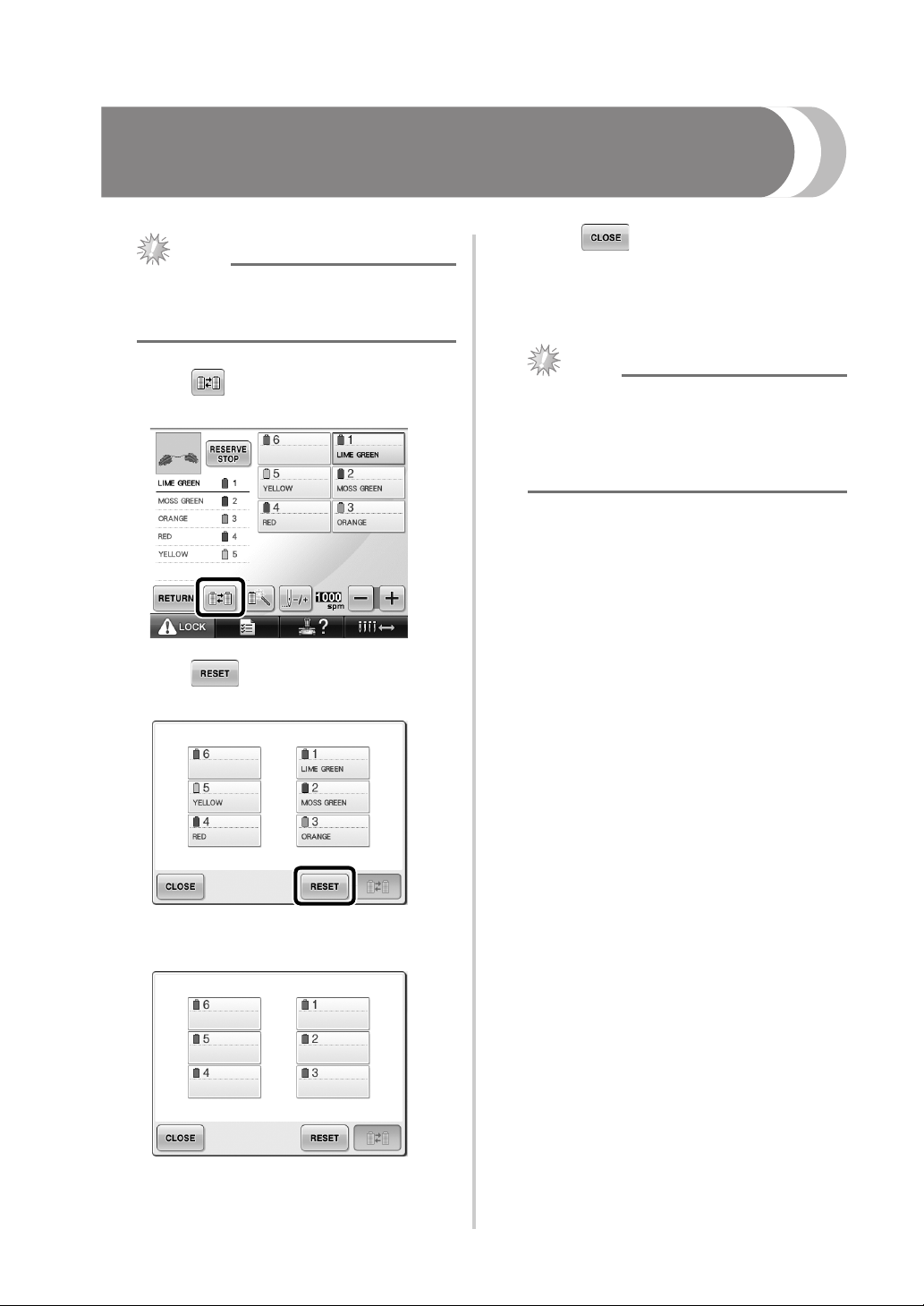
Cancelling the Thread Color Settings for All Previously
Stitched Design
Touch .
Note
● The color settings will be completely
canceled even if the machine is in the
middle of the embroidery.
3
X Thread colors are assigned by the machine
again, regardless of the previous spool
setting.
Touch .
1
Touch .
2
Note
● This function will not clear anchor settings
of any of the needles which have been
assigned a thread color (Refer to “Reserved
Needle Bar Settings” on page 132 in the
PR650e Operation Manual).
X The thread color setting is canceled.
2
Page 4
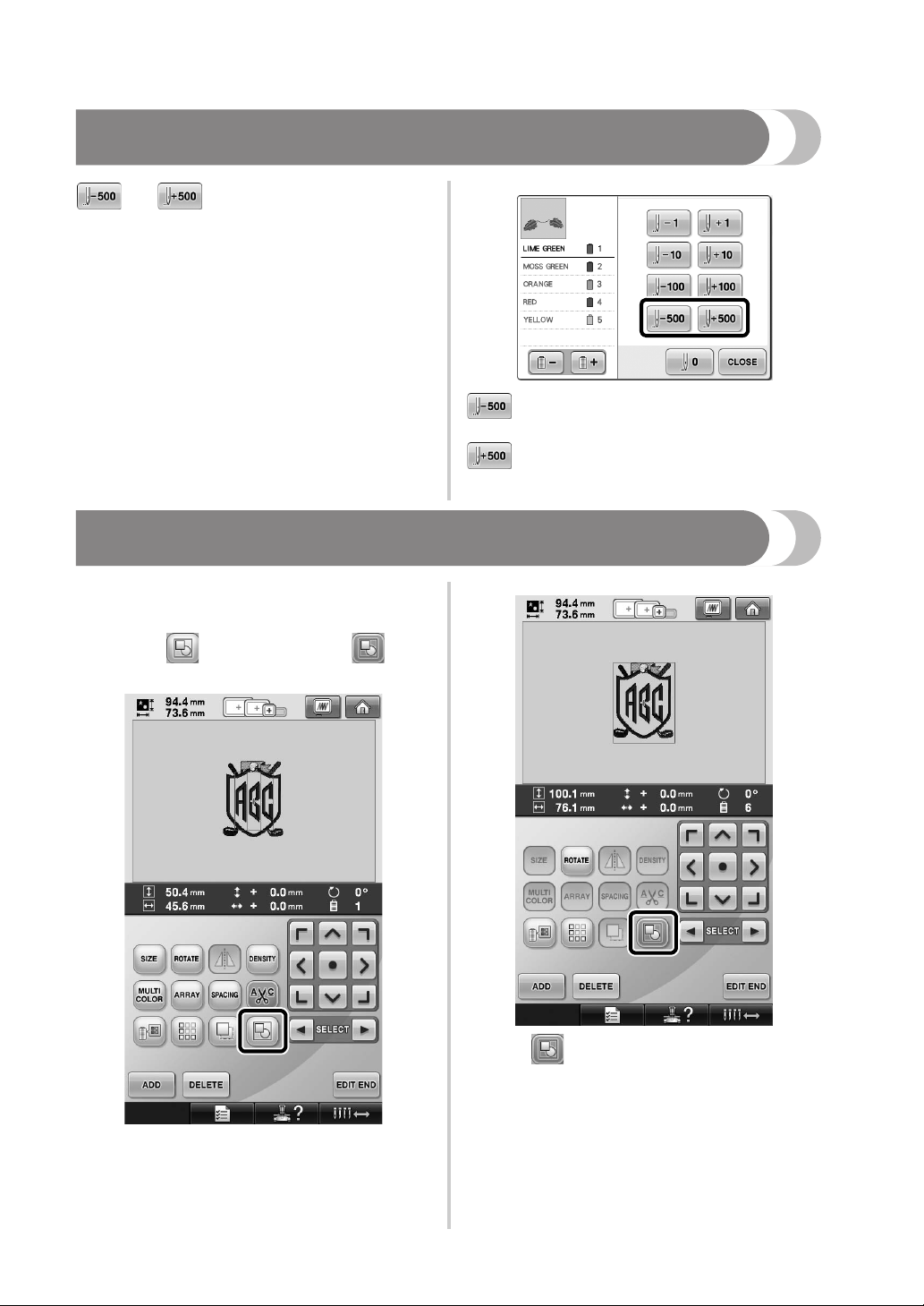
Moving Five Hundred Stitches Forward/Back
and have been added to the stitch
navigation screen. For details on moving forward or
backward through the stitching, refer to
“Embroidering From the Beginning or Middle of the
Pattern” on page 108 of the PR650e Operation
Manual.
Each touch of this key moves five hundred
stitches back through the stitching.
Each touch of this key moves five hundred
stitches forward through the stitching.
Editing Patterns as a Group
Combined patterns can be grouped and can all be
edited (rotated, resized, etc.) at the same time.
Touch so that it changes to .
1
X All patterns displayed in the pattern
display area are grouped.
* Touch to ungroup the patterns. If there are
multiple grouped patterns, the selected pattern group
is ungrouped.
3
Page 5

Sewing the repeated
pattern without sorting
colors
With repeated patterns created using the border
function, pressing automatically changes
the sewing order of the colors so that the same
color can be continuously sewn. You can edit the
pattern according to the procedure below to sew
the repeated pattern without sorting the colors.
Create the combined border embroidery
1
pattern (Refer to “Designing repeated
patterns” on page 172 in the PR650e
Operation Manual).
Touch so that it changes to .
2
X The border function is canceled.
If necessary, touch so that the patterns
3
are regrouped.
X All patterns displayed in the pattern
display area are grouped.
If necessary touch to sew the thread
4
mark, and then touch .
(Refer to page 175 in the PR650e Operation
Manual)
4
Page 6

Touch , then .
5
Sending Embroidery Patterns From a Computer to the
Machine (Link Function)
■ Check the sewing status of the embroidery
Operations available with
the Link function
■ Send multiple embroidery patterns to
connected embroidery machines
As many as 100 embroidery patterns can be
transferred to an embroidery machine, and the
embroidering status of the patterns being
transferred can be viewed from the computer
monitor.
Use the included USB cable to connect the
embroidery machine to a computer.
machine (this model) from the computer
(Example of multiple machines connected)
5
Page 7

Memo
● When connecting multiple embroidery
machines to the computer, use a
commercially available USB hub.
Please note that we recommend using a
self-powered USB hub. Do not use USB
extension cables or repeater cables. For
details on using the USB hub, refer to its
operating instructions.
Embroidering using
the Link function
First, use the embroidery editing software to create
the embroidery pattern to be sent to the embroidery
machine.
Touch to enable the Link function.
2
X When the following message appears,
touch .
Note
● Only embroidery data in the PES format
(.pes) can be embroidered using the Link
function.
● You cannot select .dst data to send from a
computer using the Link function.
● The Link function cannot be used with
large-size (split) embroidery patterns.
● Attach to the embroidery machine the
embroidery frame for the size of the
pattern to be sent.
Touch , and then touch and
1
to display page 5 of the machine settings
screen.
Turn off the machine.
3
Use the included USB cable to connect the
4
embroidery machine to the computer.
6
Page 8

Turn on the machine.
5
Using embroidery editing software provided
6
with the Link function, such as PE-DESIGN
NEXT, or later, will allow you to send the
embroidery pattern(s) to the machine in the
Link mode from your computer.
When the following message appears, touch
7
.
Note
● For details on using the embroidery editing
software, refer to the Instruction Manual
included with the software.
* This Link dialog box is found in PE-DESIGN
NEXT software.
● If the following error message appears, the
type of embroidery frame installed on the
machine is not compatible with the size of
the pattern. Replace the embroidery frame
with one compatible with the size of the
pattern.
X A message appears in the machine’s LCD
while the machine is connecting to PC.
7
Page 9

After the embroidery pattern has been
8
opened by the machine, the embroidering
screen appears.
X The opened embroidery pattern appears in
the pattern display area with the icon for
the Link function.
1
2
3
1 Icon for Link function
2 10-digit machine ID
3 Number of the pattern in the queue
• Touch to delete the pattern.
To change the embroidery settings for the
9
opened embroidery pattern, touch .
• Touch when the following message
appears. Touch to return to the
embroidering screen.
X The embroidery settings screen appears.
After the desired settings have been
0
specified, touch to return to the
embroidering screen.
Memo
● While the embroidery machine is
connected to the computer, the machine’s
status can be displayed by using a function
of the embroidery editing software. If
multiple embroidery machines are
connected at the same time, check the
status of the machines using the 10-digit
machine ID that appears in the machine’s
screen. The following information can be
viewed from the computer.
• Number of the stitch being sewn and
total number of stitches in the pattern
• Information about sewing errors
Touch , and then press the start/
a
stop button to start embroidering.
X When embroidering is finished, the
following message appears.
8
Page 10

To open another pattern sent from the
b
computer, touch , and then repeat the
procedure starting from step
8 to continue
embroidering.
• To stop embroidering or to embroider the
same pattern again, touch .
Note
● The embroidering screen settings specified
in step
0 are saved even if was
touched to continue sewing after
embroidering is finished.
Memo
● If the embroidery machine is turned off
while it is embroidering, the resume
operation can be used the next time it is
turned on.
Disabling the Link function
Touch , and then touch and
1
2
to display page 5 of the machine settings
screen.
Touch to disable the Link function.
X When the following message appears,
touch .
Turn off the machine.
3
9
Page 11

.
Error messages in the
Link function
Machine cannot receive any data
from the PC in the Link mode.
Turn off the machine, and check
the USB connection. After
connecting the USB cord securely,
turn on the machine again.
Machine failed to communicate
with the PC in the Link mode.
Turn the machine off, and then turn
the machine on again.
Selecting the Thread Color Information for “PES”
Format Data
Refer to page 194 in the PR650e Operation Manual
for the details of understanding the machine's
settings screen.
You can display the thread color for “PES” format
data according to the machine setting, or setting
from the PE-DESIGN, PE-DESIGN Lite or PED-Basic
(embroidery editing software).
(Refer to “Changing the thread color information”
on page 197 in the PR650e Operation Manual for
the machine setting of thread color.)
The “PES” Thread Code can be selected from page
1/6 of the settings screen.
ON: The thread color information will be displayed
according to the PE-DESIGN, PE-DESIGN Lite or
PED-Basic (embroidery editing software) settings.
OFF: The thread color information displayed will
be according to the machine setting.
When the machine is purchased, “ON” is selected.
10
Page 12

Checking the Length of Time until the Machine’s Next
Stop
The length of time until the embroidery machine's
next stop can be viewed in the embroidering
screen.
The machine stops when a spool change is
required, or when the machine is set to be stopped
by other settings. If the spool change indicator
appears, the machine will require a spool change.
When the time is indicated in red, this signals the
last color to be embroidered before the machine
stops.
1
Note
● The displayed information differs from that
in Ver. 1 (described in the PR650e
Operation Manual).
1 Time until the machine stops
Checking the Temporary Needle Bar Setting
The needle bar with the temporary needle bar
setting applied can now be viewed in the
embroidering screen.
For details on the temporary needle bar setting,
refer to page 130 in your PR650e Operation
Manual.
11
1
1 The needle bar number changes and
appears to indicate the selected needle bar.
English
884-T07
XE9984-001
Printed in Taiwan
 Loading...