

Brother 882-W01, 882-W02 User Manual
Computerized
Embroidery and Sewing Machine
Operation Manual
Product Code: 882-W01/W02

Trademarks
FlashFX® is a registered trademark of Datalight, Inc.
FlashFX
U.S.Patent Office 5,860,082/6,260,156
FlashFX
Datalight
Copyright 1989-2007 Datalight, Inc., All Rights Reserved
Video powered by Mobiclip™ encoding and playback technology.
“Adobe” and “Adobe Reader” are either registered trademarks or trademarks of Adobe Systems
Incorporated in the United States and/or other countries.
IMPORTANT:
READ BEFORE DOWNLOADING, COPYING, INSTALLING OR USING.
By downloading, copying, installing or using the software you agree to this license. If you do not agree
to this license, do not download, install, copy or use the software.
Intel License Agreement For Open Source Computer Vision Library
Copyright © 2000, Intel Corporation, all rights reserved. Third party copyrights are property of their respective owners.
®
Copyright 1998-2007 Datalight, Inc.
®
Pro™ is a trademark of Datalight, Inc.
®
is a registered trademark of Datalight, Inc.
Redistribution and use in source and binary forms, with or without modification, are permitted provided
that the following conditions are met:
• Redistribution's of source code must retain the above copyright notice, this list of conditions and the
following disclaimer.
• Redistribution's in binary form must reproduce the above copyright notice, this list of conditions and
the following disclaimer in the documentation and/or other materials provided with the distribution.
• The name of Intel Corporation may not be used to endorse or promote products derived from this
software without specific prior written permission.
This software is provided by the copyright holders and contributors “as is” and any express or implied
warranties, including, but not limited to, the implied warranties of merchantability and fitness for a
particular purpose are disclaimed. In no event shall Intel or contributors be liable for any direct, indirect,
incidental, special, exemplary, or consequential damages (including, but not limited to, procurement of
substitute goods or services; loss of use, data, or profits; or business interruption) however caused and on
any theory of liability, whether in contract, strict liability, or tort (including negligence or otherwise)
arising in any way out of the use of this software, even if advised of the possibility of such damage.
All information provided related to future Intel products and plans is preliminary and subject to change at any time, without
notice.

INTRODUCTION
INTRODUCTION
Thank you for purchasing this embroidery and sewing machine. Before using this machine, carefully read
the “Important Safety Instructions”, and then study this manual for the correct operation of the various
functions.
In addition, after you have finished reading this manual, store it where it can quickly be accessed for
future reference.
IMPORTANT SAFETY INSTRUCTIONS
Please read these safety instructions before attempting to use the machine.
This machine is intended for household use.
DANGER - To reduce the risk of electric shock
1Always unplug the machine from the electrical outlet immediately after using, when cleaning, when making any
user servicing adjustments mentioned in this manual, or if you are leaving the machine unattended.
WARNING - To reduce the risk of burns, fire, electric shock, or injury to persons.
2Always unplug the machine from the electrical outlet when removing covers, lubricating, or when making any
adjustments mentioned in the instruction manual.
• To unplug the machine, switch the machine to the symbol “O” position to turn it off, then grasp the plug and pull
it out of the electrical outlet. Do not pull on the cord.
• Plug the machine directly into the electrical outlet. Do not use an extension cord.
• Always unplug your machine if the power is cut.
3Never operate this machine if it has a damaged cord or plug, if it is not working properly, if it has been dropped
or damaged, or water is spilled on the unit. Return the machine to the nearest authorized dealer or service center
for examination, repair, electrical or mechanical adjustment.
• While the machine is stored or in use if you notice anything unusual, such as an odor, heat, discoloration or
deformation, stop using the machine immediately and unplug the power cord.
• When transporting the sewing machine, be sure to carry it by its handle. Lifting the sewing machine by any other
part may damage the machine or result in the machine falling, which could cause injuries.
• When lifting the sewing machine, be careful not to make any sudden or careless movements, otherwise you may
injure your back or knees.
4Always keep your work area clear:
• Never operate the machine with any air openings blocked. Keep ventilation openings of the sewing machine
and foot control free from the build up of lint, dust, and loose cloth.
• Do not store objects on the foot controller.
• Do not use extension cords. Plug the machine directly into the electrical outlet.
• Never drop or insert any object into any opening.
• Do not operate where aerosol (spray) products are being used or where oxygen is being administered.
• Do not use the machine near a heat source, such as a stove or iron; otherwise, the machine, power cord or
garment being sewn may ignite, resulting in fire or an electric shock.
• Do not place this sewing machine on an unstable surface, such as an unsteady or slanted table, otherwise the
sewing machine may fall, resulting in injuries.
i

IMPORTANT SAFETY INSTRUCTIONS
5Special care is required when sewing:
• Always pay close attention to the needle. Do not use bent or damaged needles.
• Keep fingers away from all moving parts. Special care is required around the machine needle.
• Switch the sewing machine to the symbol “O” position to turn it off when making any adjustments in the needle
area.
• Do not use a damaged or incorrect needle plate, as it could cause the needle to break.
• Do not push or pull the fabric when sewing, and follow careful instruction when free motion stitching so that
you do not deflect the needle and cause it to break.
6This machine is not a toy:
• Your close attention is necessary when the machine is used by or near children.
• The plastic bag that this sewing machine was supplied in should be kept out of the reach of children or disposed
of. Never allow children to play with the bag due to the danger of suffocation.
• Do not use outdoors.
7For a longer service life:
• When storing this machine, avoid direct sunlight and high humidity locations. Do not use or store the machine
near a space heater, iron, halogen lamp, or other hot objects.
• Use only neutral soaps or detergents to clean the case. Benzene, thinner, and scouring powders can damage the
case and machine, and should never be used.
• Always consult the operation manual when replacing or installing any assemblies, the presser feet, needle, or
other parts to assure correct installation.
8For repair or adjustment:
• If the light unit is damaged, it must be replaced by an authorized dealer.
• In the event a malfunction occurs or adjustment is required, first follow the troubleshooting table in the back of
the operation manual to inspect and adjust the machine yourself. If the problem persists, please consult your
local authorized Brother dealer.
Use this machine only for its intended use as described in the manual.
Use accessories recommended by the manufacturer as contained in this manual.
Use only the interface cable (USB cable) included with this machine.
Use only the USB mouse included with this machine.
The contents of this manual and specifications of this product are subject to change without notice.
For additional product information and updates, visit our website at www.brother.com
SAVE THESE INSTRUCTIONS
ii

IMPORTANT SAFETY INSTRUCTIONS
FOR USERS IN THE UK, EIRE, MALTA
AND CYPRUS ONLY
IMPORTANT
• In the event of replacing the plug fuse, use a fuse approved by ASTA to BS 1362, i.e. carrying the mark,
rating as marked on plug.
• Always replace the fuse cover. Never use plugs with the fuse cover omitted.
• If the available electrical outlet is not suitable for the plug supplied with this equipment, you should contact your
authorized dealer to obtain the correct lead.
FOR USERS IN AC INPUT 220-240V COUNTRIES
This appliance is not intended for use by persons (including children) with reduced physical, sensory or mental
capabilities, or lack of experience and knowledge, unless they have been given supervision or instruction
concerning use of the appliance by a person responsible for their safety. Children should be supervised to ensure
that they do not play with the appliance.
iii

IMPORTANT SAFETY INSTRUCTIONS
Federal Communications Commission (FCC)
Declaration of Conformity (For USA Only)
Responsible Party: Brother International Corporation
100 Somerset Corporate Boulevard
Bridgewater, NJ 08807-0911 USA
TEL : (908) 704-1700
declares that the product
Product Name:
Model Number:
This device complies with Part 15 of the FCC Rules. Operation is subject to the following two conditions: (1) this
device may not cause harmful interference, and (2) this device must accept any interference received, including
interference that may cause undesired operation.
This equipment has been tested and found to comply with the limits for a Class B digital device, pursuant to Part 15
of the FCC Rules. These limits are designed to provide reasonable protection against harmful interference in a
residential installation. This equipment generates, uses, and can radiate radio frequency energy and, if not installed
and used in accordance with the instructions, may cause harmful interference to radio communications. However,
there is no guarantee that interference will not occur in a particular installation. If this equipment does cause
harmful interference to radio or television reception, which can be determined by turning the equipment off and on,
the user is encouraged to try to correct the interference by one or more of the following measures:
Brother Sewing Machine
NV6000D
• Reorient or relocate the receiving antenna.
• Increase the separation between the equipment and receiver.
• Connect the equipment into an outlet on a circuit different from that to which the receiver is connected.
• Consult the dealer or an experienced radio/TV technician for help.
• The included interface cable should be used in order to ensure compliance with the limits for a Class B digital
device.
• Changes or modifications not expressly approved by Brother Industries, Ltd. could void the user's authority to
operate the equipment.
iv
IMPORTANT SAFETY INSTRUCTIONS
CAUTION
WARNING LABEL
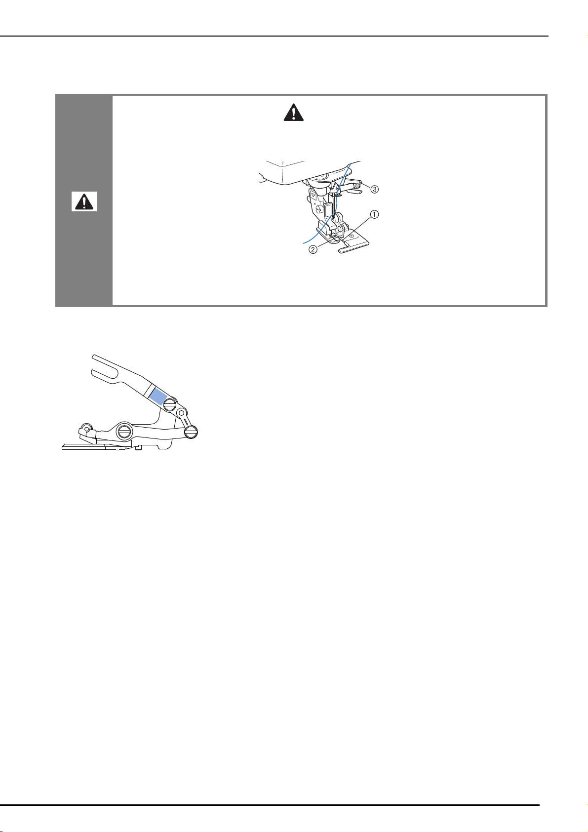
The following warning label is on the included side cutter. Be sure to observe the precaution.
• When using the side cutter, sew between low and mid-speed and do not touch the knives or
operation lever of the side cutter while sewing to avoid equipment damage or injury.
a Guide plate (lower knife)
b Upper knife
c Operation lever
Label location
v
OUTSTANDING FEATURES
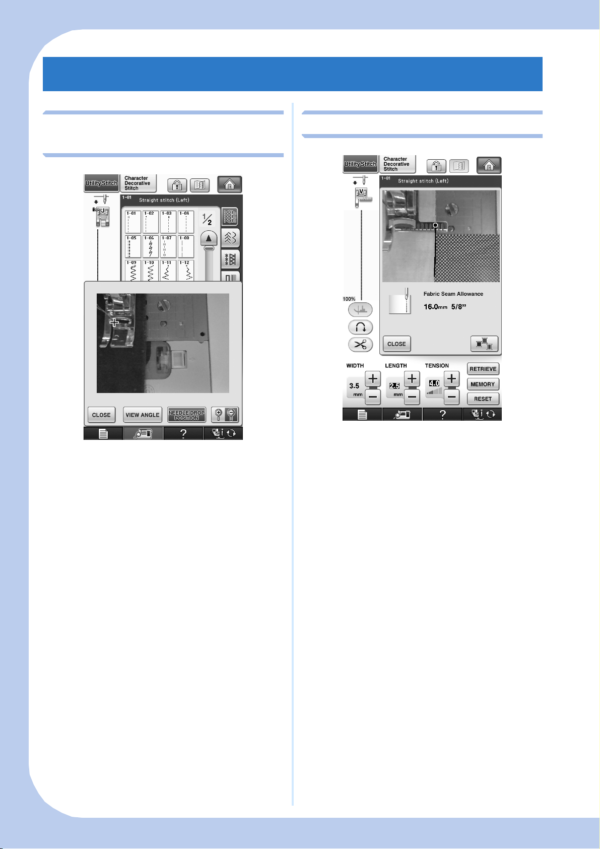
Checking the Needle Location in
the Screen
Edge Sewing
You can check the needle drop position on the
screen of your machine, even if the needle has not
actually been lowered. Also, you can view the
location of the needle within the sewing area in
the screen.
See “Checking the Needle Location in the Screen”
on page 75.
Using the built-in camera, the width of the area
from the edge of the fabric to the stitching line can
be measured and set for edge sewing.
See “Edge Sewing” on page 138.
vi
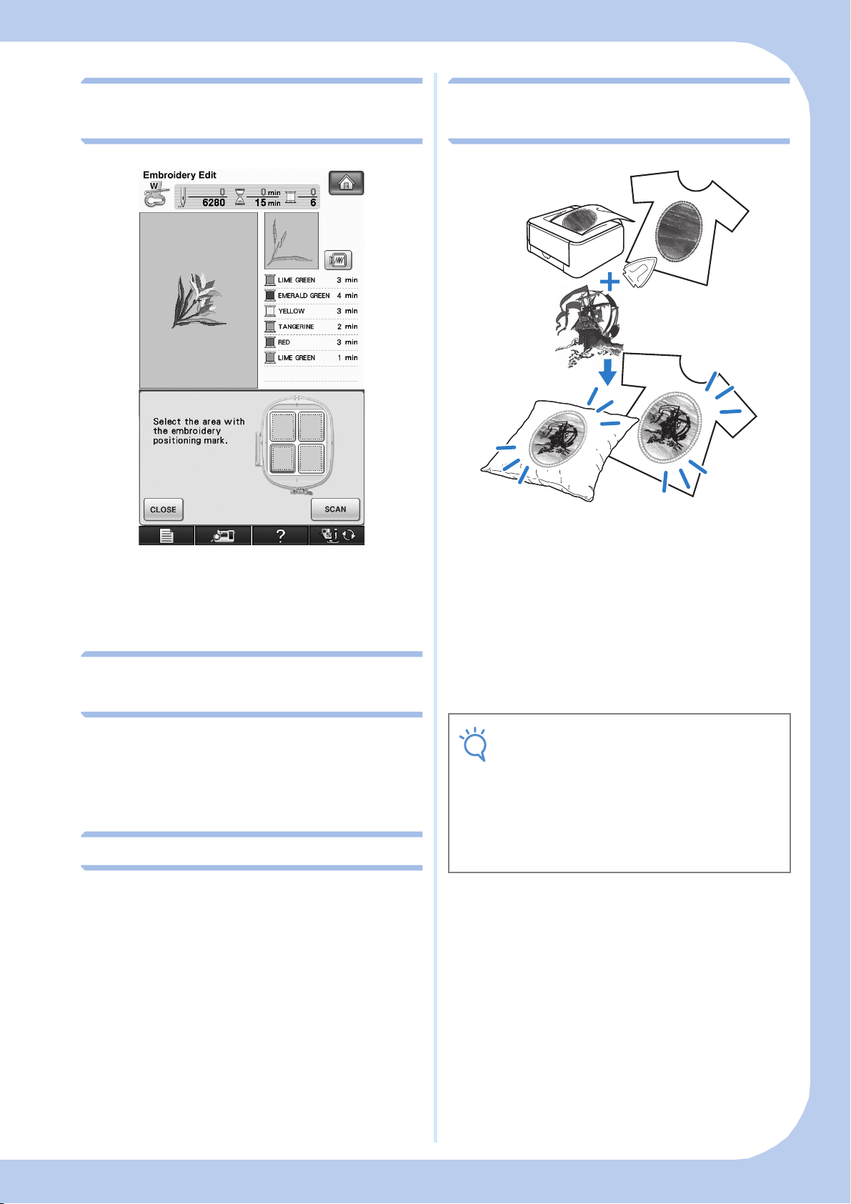
Using the Built-In Camera to
Note
Print and Stitch (Combining the
Align the Embroidering Position
The embroidering position can easily be aligned
by using the machine’s built-in camera and the
enclosed embroidery positioning sticker.
See “Using the Built-In Camera to Align the
Embroidering Position” on page 206 and 302.
Uninterrupted Embroidering
(Using a Single Color)
Embroidery and Printing)
Completed embroidery patterns can be combined
with printed backgrounds that are built into this
machine.
Beautiful three-dimensional embroidered designs
can be created by ironing a background onto
fabric or printing it onto printable fabric, and then
embroider a design to compliment the
background.
See “PRINT AND STITCH (COMBINING
EMBROIDERY PATTERNS AND PRINTED
DESIGNS)” on page 217 and 306.
You can embroider a multi-color pattern with a single
color without stopping the machine while
embroidering.
See “Uninterrupted Embroidering (Using a Single
Color)” on page 295.
Duplicating a Pattern
You can duplicate a desired pattern with one touch.
See “Duplicating a Pattern” on page 290.
• Print the background and embroidery
position sheet in their original dimensions. If
an image is printed in a different size, the
sizes of the embroidery pattern and
background may not match. In addition, the
built-in camera cannot detect the
embroidery position mark. Make sure that
the print settings are correctly specified.
vii

WHAT YOU CAN DO WITH THIS MACHINE
Getting Ready
To learn the operation of the principal parts and the
screens
Chapter 1
Page 11
Utility Stitches
Pre-programmed with more than 100 frequently used
stitches
Chapter 3
Page 77
Embroidery
Maximum 30 cm × 20 cm (approx. 12 × 8 inches) for
large embroidery designs
Sewing Basics
To learn how to prepare for sewing and basic sewing
operations
Chapter 2
Page 59
Character/Decorative
Stitches
The variety of stitches widen your creativity
Chapter 4
Page 145
Embroidery Edit
Designs can be combined, rotated or enlarged
Chapter 5
Page 181
My Custom Stitch
Create original decorative stitches
Chapter 7
Page 313
Chapter 6
Page 261
Appendix
Caring for your machine and dealing with errors and
malfunctions
Chapter 8
Page 325
viii
HOW TO USE THIS MANUAL
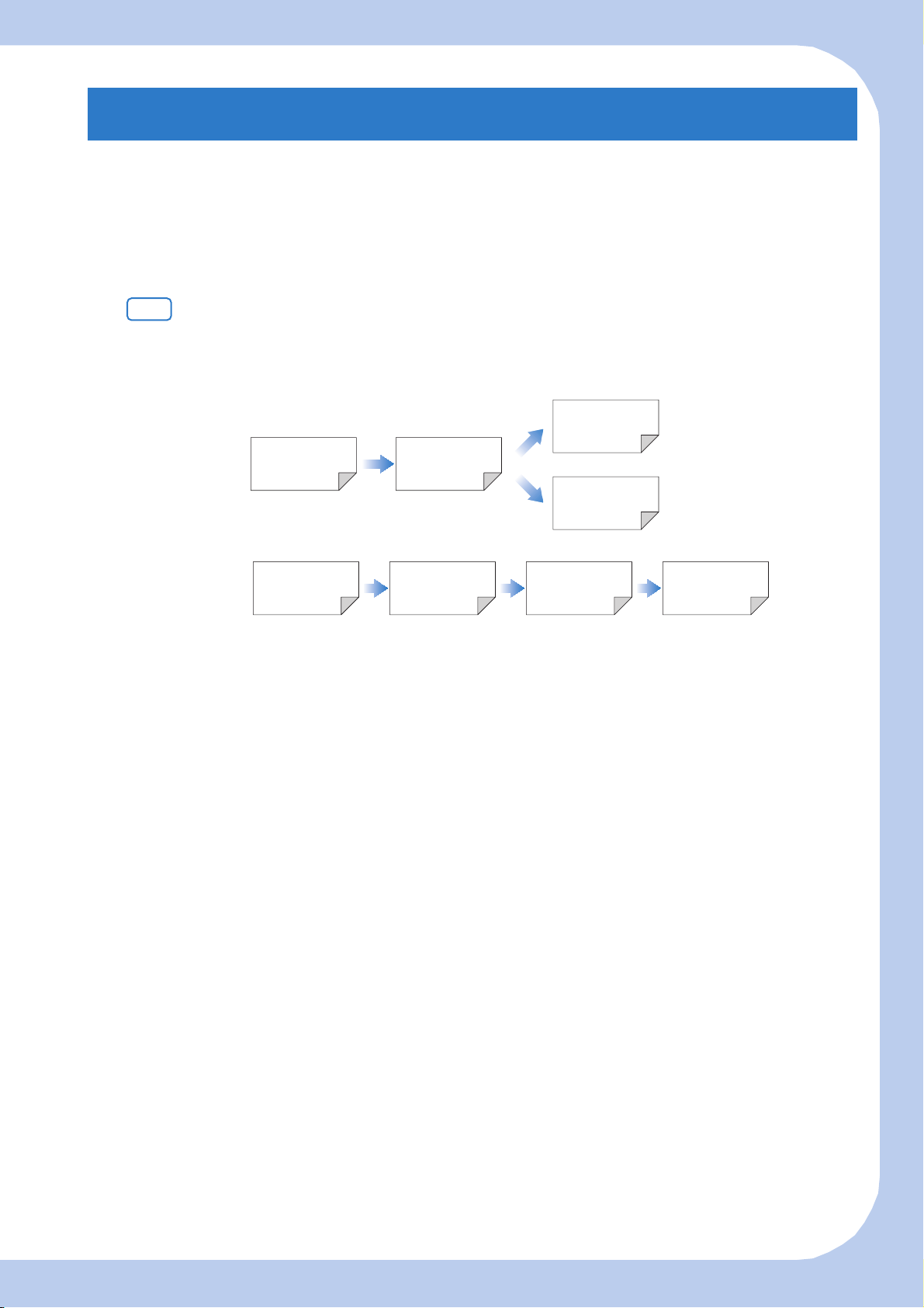
Chapter 1 and Chapter 2 explain your sewing machine’s basic operation procedures for someone who is
using the sewing machine for the first time. If you want to sew utility stitches or character/ decorative
stitches, read Chapter 1 and Chapter 2, then go on to Chapter 3 (Utility Stitches) or Chapter 4 (Character/
Decorative Stitches).
When you are ready to begin using the embroidery function after reading Chapter 1 and Chapter 2,
proceed to Chapter 5 (Embroidery). Once you understand the steps explained in Chapter 5, go on to
Chapter 6 (Embroidery Edit) for an explanation about the embroidery edit functions.
In the screens appearing in the step-by-step instructions, the parts referred to in the operations are marked
with . Compare the screen in the directions with the actual screen, and carry out the operation.
If, while using the machine, you experience something you do not understand, or there is a function you
would like to know more about, refer to the index at the back of the operation manual in conjunction
with the table of contents to find the section of the manual you should refer to.
Chapter 3
To sew utility stitches
To sew character or
decorative stitches
Chapter 1 Chapter 2
Chapter 4
To do machine
embroidery
Chapter 1 Chapter 2 Chapter 5 Chapter 6
ix

CONTENTS
CONTENTS
INTRODUCTION ...................................................i
IMPORTANT SAFETY INSTRUCTIONS ..................i
OUTSTANDING FEATURES .................................vi
WHAT YOU CAN DO WITH THIS MACHINE ...viii
HOW TO USE THIS MANUAL .............................ix
NAMES OF MACHINE PARTS AND THEIR
FUNCTIONS...........................................................1
Machine..................................................................................1
Needle and Presser Foot Section .............................................2
Embroidery Unit......................................................................3
Operation Buttons...................................................................3
Using the Flat Bed Attachment................................................4
Using the Accessory Case........................................................4
Storing Bobbin Clips................................................................5
Using the Embroidery Unit Carrying Case ...............................5
Included Accessories ...............................................................5
Options...................................................................................8
Using the Spool Stand .............................................................9
Chapter 1 Getting Ready 11
TURNING THE MACHINE ON/OFF....................12
LCD SCREEN .......................................................14
USB Connectivity ..................................................................18
Using the Machine Setting Mode Key ...................................22
Using the Sewing Machine Help Key ...................................32
Using the Operation Guide Function.....................................33
Using the Sewing Guide Function .........................................34
Using the Pattern Explanation Function.................................35
LOWER THREADING ..........................................37
Winding the Bobbin ..............................................................37
Setting the Bobbin .................................................................43
Pulling Up the Bobbin Thread ...............................................45
UPPER THREADING............................................46
Upper Threading...................................................................46
Using the Twin Needle Mode................................................49
Using the Spool Stand ...........................................................52
Using Threads that Unwind Quickly .....................................53
CHANGING THE PRESSER FOOT .......................54
Removing the Presser Foot ....................................................54
Attaching the Presser Foot .....................................................54
Attaching the Walking Foot ...................................................55
CHANGING THE NEEDLE...................................56
About the Needle ..................................................................58
Fabric/Thread/Needle Combinations .....................................58
Chapter 2 Sewing Basics 59
SEWING ..............................................................60
Sewing a Stitch......................................................................60
Sewing Reinforcement Stitches..............................................62
Sewing Curves.......................................................................62
Changing Sewing Direction ...................................................63
Sewing Heavyweight Fabrics .................................................63
Sewing Hook-and-Loop Fastener ...........................................64
Sewing Lightweight Fabrics ...................................................64
Sewing Stretch Fabrics...........................................................65
STITCH SETTINGS...............................................66
Setting the Stitch Width .........................................................66
Setting the Stitch Length ........................................................67
Setting the Thread Tension ....................................................67
USEFUL FUNCTIONS..........................................69
Automatic Reinforcement Stitching .......................................69
Automatic Thread Cutting .....................................................70
Using the Knee Lifter .............................................................71
Pivoting.................................................................................72
Automatic Fabric Sensor System
(Automatic Presser Foot Pressure) .......................................... 73
Needle Position – Stitch Placement....................................... 74
Locking the Screen ............................................................... 74
Checking the Needle Location in the Screen......................... 75
Chapter 3 Utility Stitches 77
SELECTING UTILITY STITCHES .......................... 78
Selecting a Stitch .................................................................. 79
Saving Your Stitch Settings .................................................... 81
SEWING THE STITCHES ..................................... 83
Straight Stitches .................................................................... 83
Dart Seam............................................................................. 88
Gathering ............................................................................. 88
Flat Fell Seam ....................................................................... 89
Pintuck ................................................................................. 90
Zigzag Stitches...................................................................... 91
Elastic Zigzag Stitches ........................................................... 93
Overcasting .......................................................................... 94
Quilting................................................................................ 99
Blind Hem Stitches............................................................. 111
Appliqué............................................................................. 113
Shelltuck Stitches ................................................................ 114
Scallop Stitches................................................................... 115
Crazy Quilting.................................................................... 116
Smocking Stitches............................................................... 116
Fagoting.............................................................................. 117
Tape or Elastic Attaching .................................................... 117
Heirloom............................................................................ 119
One-step Buttonholes ......................................................... 121
Four-step Buttonholes ......................................................... 125
Bar Tacks............................................................................ 129
Button Sewing .................................................................... 131
Eyelet.................................................................................. 133
Multi-directional Sewing (Straight Stitch and Zigzag Stitch)......... 134
Zipper Insertion.................................................................. 135
Edge Sewing ....................................................................... 138
Chapter 4 Character/Decorative Stitches 145
SELECTING STITCH PATTERNS ........................ 146
Selecting Decorative Stitch Patterns/7mm Decorative Stitch
Patterns/Satin Stitch Patterns/7mm Satin Stitch Patterns/
Cross Stitch/Utility Decorative Stitch Patterns ..................... 148
Alphabet Characters ........................................................... 148
SEWING STITCH PATTERNS ............................ 152
Sewing Attractive Finishes .................................................. 152
Basic Sewing ...................................................................... 152
Making Adjustments........................................................... 153
EDITING STITCH PATTERNS............................ 155
Changing the Size............................................................... 157
Changing the Length (for 7mm Satin Stitch Patterns Only)........... 157
Creating a Vertical Mirror Image......................................... 157
Creating a Horizontal Mirror Image .................................... 158
Sewing a Pattern Continuously ........................................... 158
Changing Thread Density (for Satin Stitch Patterns Only) .... 158
Returning to the Beginning of the Pattern............................ 159
Checking the Image............................................................ 160
COMBINING STITCH PATTERNS..................... 162
Before Combining............................................................... 162
Combining Various Stitch Patterns ...................................... 162
Combining Large and Small Stitch Patterns ......................... 164
Combining Horizontal Mirror Image Stitch Patterns ............ 165
Combining Stitch Patterns of Different Length..................... 165
Making Step Stitch Patterns (for 7mm Satin Stitch Patterns Only)...... 166
USING THE MEMORY FUNCTION .................. 169
Stitch Data Precautions ....................................................... 169
Saving Stitch Patterns in the Machine’s Memory................. 171
Saving Stitch Patterns to USB Media ................................... 174
Saving Stitch Patterns in the Computer................................ 175
Retrieving Stitch Patterns from the Machine’s Memory ....... 176
x

CONTENTS
Recalling from USB Media .................................................. 177
Recalling from the Computer .............................................. 179
Chapter 5 Embroidery 181
BEFORE EMBROIDERING .................................182
Embroidery Step by Step .....................................................182
Attaching Embroidery Foot “W” ..........................................183
Attaching the Embroidery Unit............................................ 184
SELECTING PATTERNS......................................186
Selecting Embroidery Patterns/Brother “Exclusives”/Greek
Alphabet Patterns/Floral Alphabet Patterns/Utility Embroidery
Patterns...............................................................................189
Selecting Alphabet Character Patterns................................. 190
Selecting Frame Patterns ..................................................... 192
Selecting Patterns from Embroidery Cards ........................... 194
Selecting Patterns from USB Media/Computer..................... 195
VIEWING THE SEWING SCREEN......................196
PREPARING THE FABRIC ..................................198
Attaching Iron-on Stabilizers (Backing) to the Fabric ........... 198
Hooping the Fabric in the Embroidery Frame ...................... 200
Embroidering Small Fabrics or Fabric Edges ........................ 203
ATTACHING THE EMBROIDERY FRAME..........204
CONFIRMING THE PATTERN POSITION.........206
Using the Built-In Camera to Align the Embroidering Position........ 206
Checking the Pattern Position ............................................. 209
Previewing the Completed Pattern ......................................210
SEWING AN EMBROIDERY PATTERN ..............212
Sewing Attractive Finishes...................................................212
Sewing Embroidery Patterns ................................................ 213
Sewing Embroidery Patterns Which Use Appliqué .............. 215
PRINT AND STITCH (COMBINING EMBROIDERY
PATTERNS AND PRINTED DESIGNS) ..............217
Selecting a Pattern ..............................................................218
Outputting the Background Image and Positioning Image........219
Printing the Background and Embroidery Position Sheet ..... 221
Sewing Embroidery Patterns ................................................ 222
ADJUSTMENTS DURING THE EMBROIDERY
PROCESS ............................................................223
If the Bobbin Runs Out of Thread........................................ 223
If the Thread Breaks During Sewing .................................... 224
Restarting from the Beginning ............................................. 225
Resuming Embroidery After Turning Off the Power ............. 225
MAKING EMBROIDERY ADJUSTMENTS ..........227
Adjusting Thread Tension ................................................... 227
Adjusting the Alternate Bobbin Case
(with No Color on the Screw).............................................. 228
Using the Automatic Thread Cutting Function
(END COLOR TRIM)...........................................................229
Using the Thread Trimming Function (JUMP STITCH TRIM).........230
Adjusting the Embroidery Speed ......................................... 231
Changing the Thread Color Display .................................... 231
Changing the Embroidery Frame Display ............................ 232
REVISING THE PATTERN ..................................234
Changing the Pattern Position .............................................234
Aligning the Pattern and the Needle.................................... 235
Changing the Size............................................................... 236
Rotating the Pattern............................................................. 237
Creating a Horizontal Mirror Image .................................... 238
Changing the Density
(Alphabet Character and Frame Patterns Only).................... 239
Changing the Colors of Alphabet Character Patterns ...........240
Embroidering Linked Characters ......................................... 241
Uninterrupted Embroidering (Using a Single Color)............. 243
USING THE MEMORY FUNCTION...................244
Embroidery Data Precautions.............................................. 244
Saving Embroidery Patterns in the Machine’s Memory ........ 246
Saving Embroidery Patterns to USB Media .......................... 249
Saving Embroidery Patterns in the Computer ....................... 250
Retrieving Patterns from the Machine’s Memory ................. 251
Recalling from USB Media .................................................. 252
Recalling from the Computer .............................................. 254
EMBROIDERY APPLICATIONS ......................... 256
Using a Frame Pattern to Make an Appliqué (1)...................256
Using a Frame Pattern to Make an Appliqué (2)...................257
Sewing Split Embroidery Patterns ........................................259
Chapter 6 Embroidery Edit 261
EXPLANATION OF FUNCTIONS...................... 262
SELECTING PATTERNS TO EDIT ...................... 263
Selecting Embroidery Patterns/Brother “Exclusives”/Greek
Alphabet Patterns/Floral Alphabet Patterns/Utility Embroidery
Patterns/Frame Patterns .......................................................264
Selecting Alphabet Character Patterns .................................264
EDITING PATTERNS ......................................... 267
Moving the Pattern ..............................................................269
Rotating the Pattern .............................................................269
Changing the Size of the Pattern.......................................... 270
Deleting the Pattern.............................................................271
Changing the Configuration of Alphabet Character Patterns ........ 271
Changing Alphabet Character Spacing ................................272
Reducing Character Spacing................................................273
Separating Combined Character Patterns.............................274
Changing the Color of Each Alphabet Character in a Pattern ....... 275
Embroidering Linked Characters ..........................................276
Changing the Thread Color .................................................278
Creating a Custom Thread Table .........................................279
Choosing a Color from the Custom Thread Table ................283
Designing Repeated Patterns ...............................................284
Duplicating a Pattern...........................................................290
After Editing ........................................................................290
COMBINING PATTERNS .................................. 291
Editing Combined Patterns ..................................................291
Sewing Combined Patterns ..................................................294
VARIOUS EMBROIDERING FUNCTIONS ........ 295
Uninterrupted Embroidering (Using a Single Color) .............295
Basting Embroidery .............................................................295
Creating an Appliqué Piece .................................................296
Using the Built-In Camera to Align the Embroidering Position .........302
USING THE MEMORY FUNCTION .................. 305
PRINT AND STITCH (COMBINING EMBROIDERY
PATTERNS AND PRINTED DESIGNS) .............. 306
Selecting a Pattern ...............................................................307
Outputting the Background Image and Positioning Image ...308
Printing the Background and Embroidery Position Sheet......310
Sewing Embroidery Patterns ................................................310
Chapter 7 MY CUSTOM STITCH 313
DESIGNING A STITCH ..................................... 314
ENTERING STITCH DATA ................................ 316
USING STORED CUSTOM STITCHES............... 322
Storing Custom Stitches in Your List ....................................322
Retrieving Stored Stitches ....................................................323
Chapter 8 Appendix 325
CARE AND MAINTENANCE ............................. 326
Cleaning the LCD Screen ....................................................326
Cleaning the Machine Casing ..............................................326
Cleaning the Race ...............................................................326
Cleaning the Cutter in the Bobbin Case Area .......................327
About the Maintenance Message .........................................328
ADJUSTING THE SCREEN ................................ 329
Touch Panel is Malfunctioning ............................................329
TROUBLESHOOTING ...................................... 330
ERROR MESSAGES............................................ 335
SPECIFICATIONS.............................................. 343
UPGRADING YOUR MACHINE’S SOFTWARE...... 344
Upgrade Procedure Using USB Media.................................344
Upgrade Procedure Using Computer ...................................345
STITCH SETTING CHART ................................. 347
INDEX............................................................... 356
1
2
3
4
5
6
7
8
xi

CONTENTS
xii

NAMES OF MACHINE PARTS AND THEIR FUNCTIONS
NAMES OF MACHINE PARTS AND THEIR FUNCTIONS
The names of the various parts of the sewing machine and their functions are described below. Before
using the sewing machine, carefully read these descriptions to learn the names of the machine parts.
Machine
■ Front View
a Top cover
Open the top cover to thread the machine and wind the bobbin.
b Pre-tension disk
Pass the thread around the pre-tension disk when winding the
bobbin thread. (page 37)
c Thread guide for bobbin winding
Pass the thread through this thread guide when winding the
bobbin thread. (page 37)
d Spool pin
Place a spool of thread on the spool pin. (page 46)
e Spool cap
Use the spool cap to hold the spool of thread in place. (page 46)
f Supplemental spool pin
Use this spool pin to wind the bobbin thread, or to sew with the
twin needle. (page 37, 49)
g Bobbin winder
Use the bobbin winder when winding the bobbin. (page 37)
h LCD (liquid crystal display)
Settings for the selected stitch and error messages appear in
the LCD. (page 14)
i Knee lifter
Use the knee lifter to raise and lower the presser foot. (page 71)
j Knee lifter slot
Insert the knee lifter into the slot. (page 71)
k Operation buttons (6 buttons) and sewing speed
controller
Use these buttons and the slide to operate the sewing machine.
(page 3)
l Flat bed attachment with accessory compartment
Store presser feet and bobbins in the accessory compartment
of the flat bed attachment. When sewing cylindrical pieces,
remove the flat bed attachment. (page 4)
m Thread cutter
Pass the threads through the thread cutter to cut them.
(page 48)
n Thread guide plate
Pass the thread around the thread guide plate when threading
upper thread. (page 46)
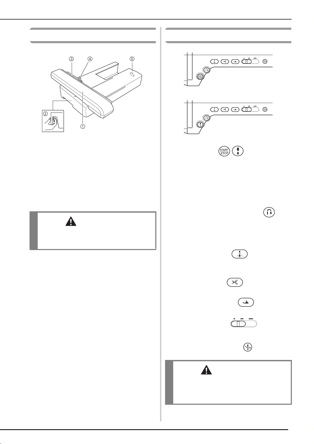
■ Right-side/Rear View
a Handle
Carry the sewing machine by its handle when transporting the
machine.
b Presser foot lever
Raise and lower the presser foot lever to raise and lower the
presser foot. (page 54)
c Main power switch
Use the main power switch to turn the sewing machine ON and
OFF. (page 12)
d Foot controller with retractable cord
Depress the foot controller to control the speed of the machine.
(page 61)
e Power cord receptacle
Insert the power cord into the machine receptacle. (page 12)
f Air vent
The air vent allows the air surrounding the motor to circulate. Do
not cover the air vent while the sewing machine is being used.
g Foot controller jack
Insert the foot controller plug into its jack on the machine.
(page 61)
h Speaker
i USB port for computer
In order to import/export patterns between a computer and the
machine, plug the USB cable into the USB port. (page 18, 175,
250)
j USB port for mouse (page 18)
k Primary (top) USB port for media
In order to send patterns from/to USB media, plug the USB
media directly into the USB port. (page 18, 174, 249)
l Touch pen holder
Use the touch pen holder to hold the touch pen when not in use.
m Handwheel
Rotate the handwheel toward you (counterclockwise) to raise
and lower the needle. The wheel should be turned toward the
front of the machine.
1
NAMES OF MACHINE PARTS AND THEIR FUNCTIONS
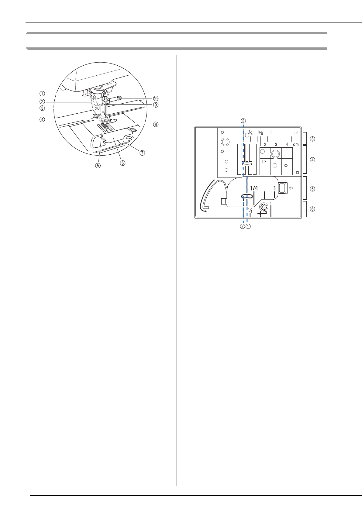
Needle and Presser Foot Section
a Buttonhole lever
The buttonhole lever is used with the one-step buttonhole foot
to create buttonholes. (page 121)
b Presser foot holder
The presser foot is attached to the presser foot holder.
(page 54)
c Presser foot holder screw
Use the presser foot holder screw to hold the presser foot in
place. (page 55)
d Presser foot
The presser foot consistently applies pressure to the fabric as
sewing takes place. Attach the appropriate presser foot for the
selected stitch. (page 54)
e Feed dogs
The feed dogs feed the fabric in the sewing direction.
f Bobbin cover
Open the bobbin cover to set the bobbin. (page 43, 92)
g Needle plate cover
Remove the needle plate cover to clean the race. (page 86,
213)
h Needle plate
The needle plate is marked with guides to help sew straight
seams. (page 85)
i Needle bar thread guide
Pass the upper thread through the needle bar thread guide.
(page 46)
j Needle clamp screw
Use the needle clamp screw to hold the needle in place.
(page 55)
Measurements on the needle plate, bobbin cover
(with mark) and needle plate cover
The measurements on the bobbin cover are
references for patterns with a middle (center)
needle position. The measurements on the needle
plate and the needle plate cover are references for
stitches with a left needle position.
a For stitches with a middle (center) needle position
b For stitches with a left needle position
c Left needle position on the needle plate <inch>
d Left needle position on the needle plate <cm>
e Middle (center) needle position on the bobbin cover
(with mark) <inch>
f Left needle position on the needle plate cover <inch>
2
NAMES OF MACHINE PARTS AND THEIR FUNCTIONS
CAUTION
CAUTION
Embroidery Unit
a Carriage
The carriage moves the embroidery frame automatically when
embroidering. (page 184)
b Release button (located under the embroidery unit)
Press the release button to remove the embroidery unit.
(page 185)
c Embroidery frame holder
Insert the embroidery frame into the embroidery frame holder to
hold the frame in place. (page 204)
d Frame-securing lever
Press the frame-securing lever down to secure the embroidery
frame. (page 204)
e Embroidery unit connection
Insert the embroidery unit connection into the connection port
when attaching the embroidery unit. (page 184)
• After the embroidery frame is set in the frame
holder, be sure the frame-securing lever is
correctly lowered.
Operation Buttons
a “Start/Stop” button
Press this button and the machine will sew a few stitches at a
slow speed and then begin sewing at the speed set by the
sewing speed controller. Press the button again to stop the
machine. Hold the button in to sew at the machine’s slowest
speed. The button changes color according to the machine’s
operation mode.
Green: The machine is ready to sew or is sewing.
Red: The machine cannot sew.
b “Reverse/Reinforcement Stitch” button
Use this button to sew reinforcement stitches at the beginning
and end of sewing. Press this button, and the machine sews 3
stitches in the same spot and stops automatically. For straight
and zigzag stitch patterns that take reverse stitches, the
machine will sew reverse stitches at low speed only while
holding down the “Reverse/Reinforcement Stitch” button (the
stitches are sewn in the opposite direction).
c “Needle Position” button
Use this button when changing sewing direction or for detailed
sewing in small areas. Press this button to raise or lower the
needle position. With this button, you can lower and raise the
needle to sew a single stitch.
d “Thread Cutter” button
Press this button after sewing to automatically trim the excess
thread.
e “Presser Foot Lifter” button
Press this button to lower the presser foot and apply pressure to
the fabric. Press this button again to raise the presser foot.
f Sewing Speed controller
Use this controller to adjust the sewing speed. Move the slide to
the left to sew at slower speeds. Move the slide to the right to
sew at higher speeds. Beginners should sew at a slow speed.
g “Automatic Threading” button
Use this button to automatically thread the needle.
• Do not press the thread cutter button after the
threads have been cut. The needle may break
and threads may become tangled, or damage
to the machine may occur.
3
NAMES OF MACHINE PARTS AND THEIR FUNCTIONS
a
b
Using the Flat Bed Attachment
Pull the top of the flat bed attachment to open the
accessory compartment.
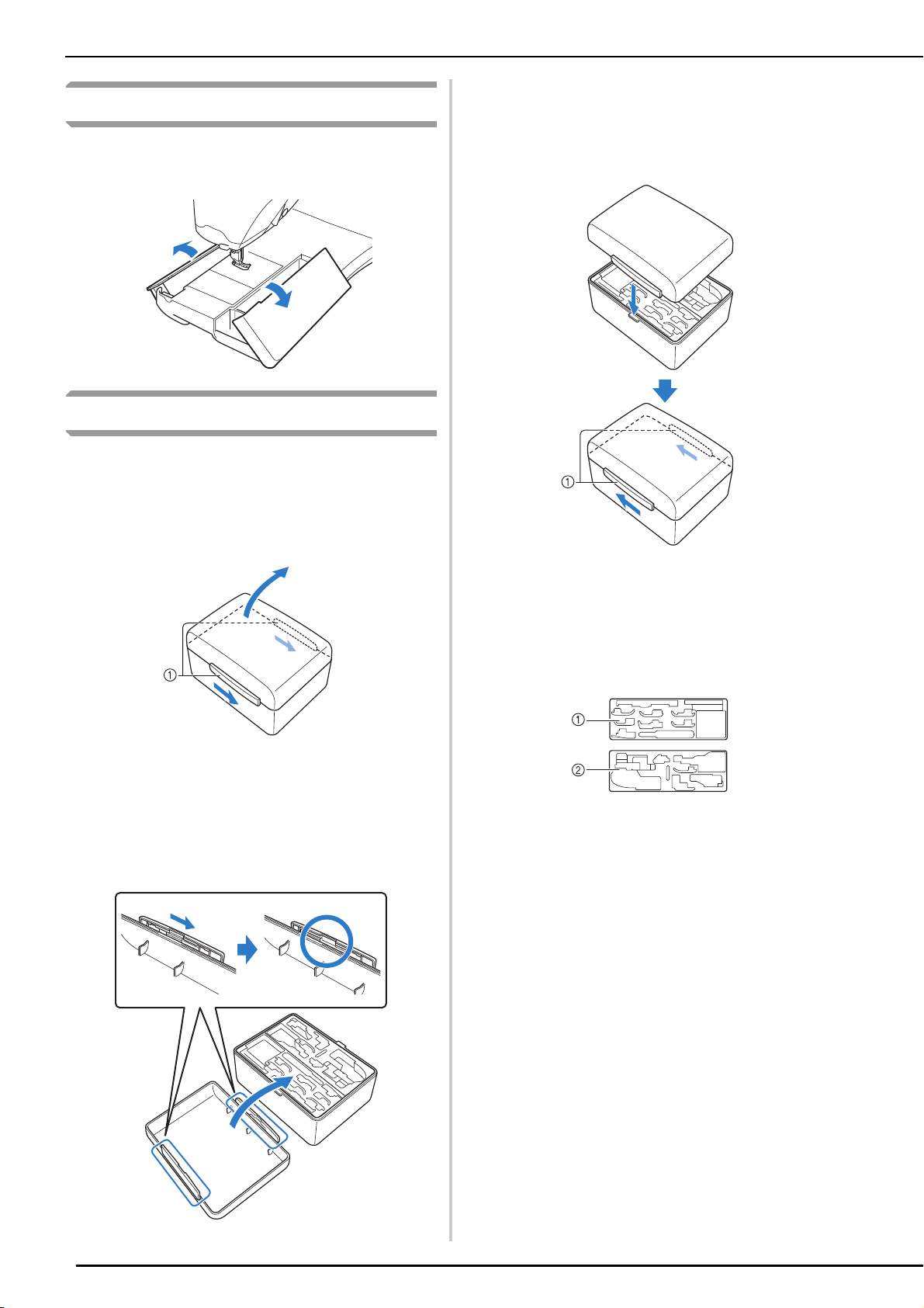
Using the Accessory Case
■ Opening the Accessory Case
Fully slide the bar on each side of the accessory
case, and then lift off the lid to open the case.
The case can only be opened or locked correctly if
both bars are slid in the same direction.
Place the lid on top of the case so that the
notches in the lid align with the tabs on the
case, and then slide the bar on each side
back to the center of the accessory case.
a Bars
a Bars
■ Closing the Accessory Case
Fully slide the bar on each side of the
accessory case lid to align the notches in
the lid with the notches in the bars.
■ Using the Accessory Trays
Two presser foot storage trays are stored in the
included accessory case. One is for presser feet for
utility sewing, and the other is for presser feet for
embroidery and machine quilting.
a For presser feet for utility sewing
b For presser feet for embroidery and machine
quilting
4
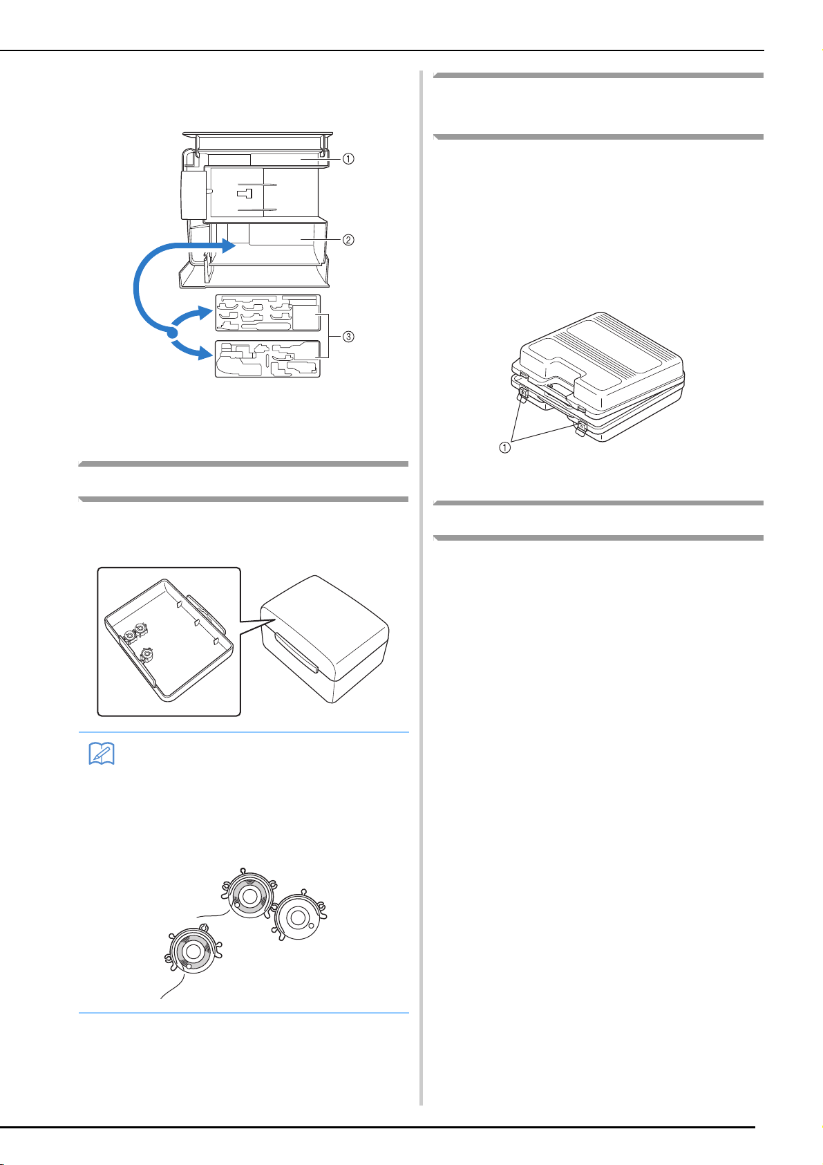
For your convenience, a presser foot storage tray
Memo
can be stored in the accessory compartment of the
flat bed attachment.
a Storage space of the flat bed attachment
b Presser foot storage space of the flat bed
attachment
c Presser foot storage trays
NAMES OF MACHINE PARTS AND THEIR FUNCTIONS
Using the Embroidery Unit
Carrying Case
Included accessories 43-46 are contained in the
embroidery unit carrying case. To open the
embroidery unit carrying case, raise each lock and
move the latches out of position. To re-hook the
latches and securely close the case, position the
latch on the catch of the unit lid and lower the
lock till it snaps.
Storing Bobbin Clips
Bobbin clips can be stored inside of the accessory
case cover.
• Placing bobbin clips on bobbins helps prevent the thread from unwinding from the
bobbin. In addition, snapping bobbin clips
together allows the bobbins to be conveniently stored and prevents them from rolling
around if they are dropped.
a Latches
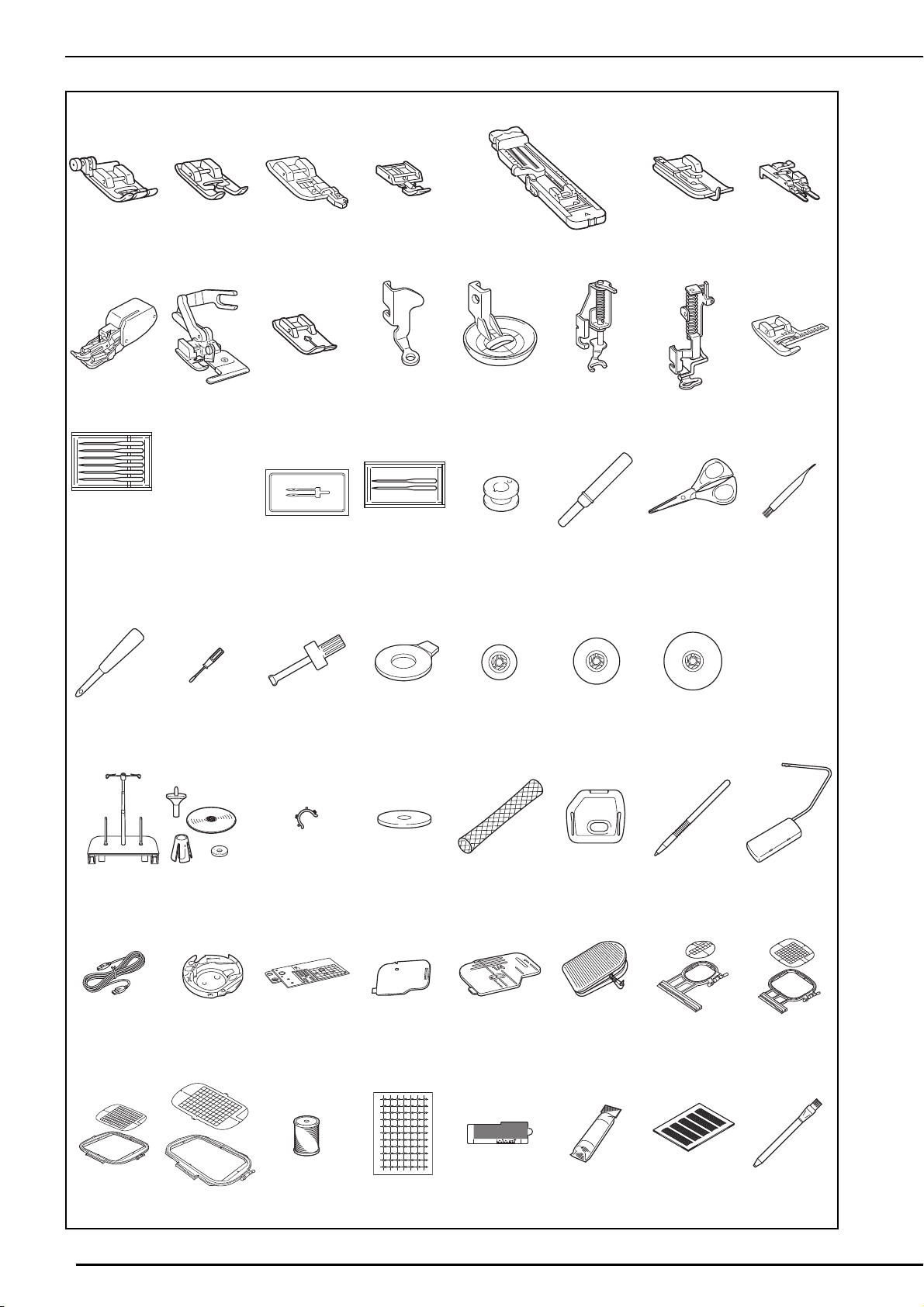
Included Accessories
See table on the next page about included
accessories.
5
NAMES OF MACHINE PARTS AND THEIR FUNCTIONS
75/11 2 needles
90/14 2 needles
90/14 2 needles:
Ball point needle (gold colored)
2.0/11 needle
75/11
2 needles
12345 67
8 9 101112131415
16 17 18 19 20 21 22
23 24 25 26 27 28 29
30 31 32 33 34 35 36
37 38 39 40 41 42
* 44*
43
45* 46* 47
*Included Accessories 43-46 are contained in the embroidery unit carrying case.
6
48 49 50 51 52
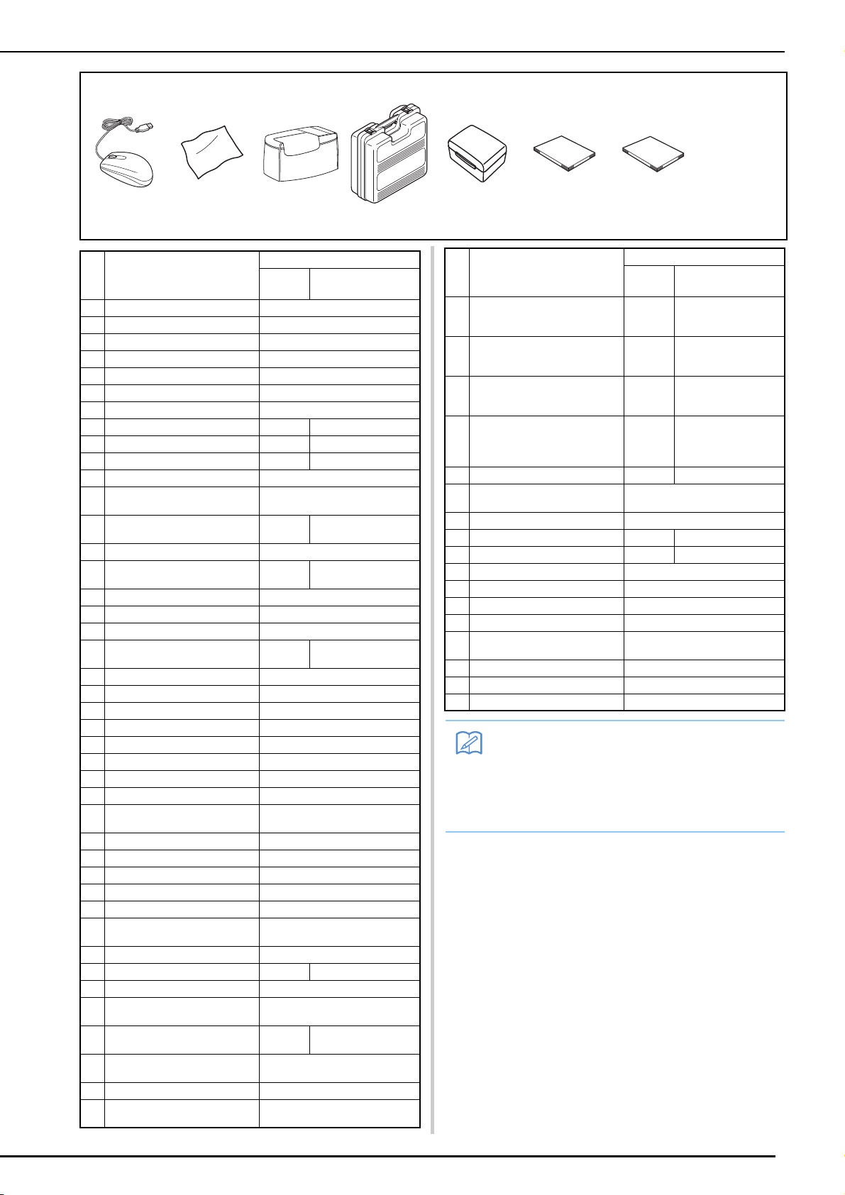
NAMES OF MACHINE PARTS AND THEIR FUNCTIONS
Memo
53 54
** 56 57
55
58 59
**In some countries or regions, this is not included in the enclosed accessories; however, it is available as an option.
Part Code
No. Part Name
1 Zigzag foot “J” (on machine) XC3021-051
2 Monogramming foot “N” X53840-351
3 Overcasting foot “G” XC3098-051
4 Zipper foot “I” X59370-051
5 Buttonhole foot “A” X57789-151
6 Blind stitch foot “R” X56409-051
7 Button fitting foot “M” 130489-001
8 Walking foot SA140 F033N: XC2214-002
9 Side cutter foot SA177 F054: XC3879-002
10 Straight stitch foot SA167 F042N: XC1973-052
11 Free motion quilting foot “C” XE0765-101
12 Free motion echo quilting foot
“E”
13 Free motion open toe quilting
foot “O”
14 Embroidery foot “W” XC8156-651
15 Vertical stitch alignment foot
“V”
16 Needle set XE4962-001
17 Twin needle XE4963-001
18 Ball point needle set XD0705-051
19 Bobbin × 10
(One is on machine.)
20 Seam ripper X54243-051
21 Scissors XC1807-121
22 Cleaning brush X59476-051
23 Eyelet punch 135793-001
24 Screwdriver (small) X55468-051
25 Screwdriver (large) XC4237-021
26 Disc-shaped screwdriver XC1074-051
27 Spool cap (small) 130013-154
28 Spool cap (medium) × 2
(One is on machine.)
29 Spool cap (large) 130012-054
30 Spool stand See page 9
31 Bobbin clip × 10 XE3060-001
32 Spool felt X57045-051
33 Spool net × 2 XA5523-050
34 Embroidery needle plate
cover
35 Touch pen (stylus) XA9940-051
36 Knee lifter SA599 KL1: XE5902-001
37 USB cable XD0745-051
38 Alternate bobbin case
(no color)
39 Straight stitch needle plate SA550 SNP01:
40 Cord guide bobbin cover
(with single hole)
41 Bobbin cover (with mark) XE0756-001
42 Foot controller XD0500-051 (EU area)
U.S.A./
Canada
SA187 F061: XE1097-001
SA189 F063: XE5224-001
SA156 SFB: XA5539-151
XC8028-051 (other area)
Others
XE0766-001
X55260-153
XE4708-001
XC8167-451
XD0606-152
XC8449-051
No. Part Name
43 Embroidery frame set (small)
H 2 cm × W 6 cm
(H 1 inch × W 2-1/2 inches)
44 Embroidery frame set
(medium) H 10 cm × W 10 cm
(H 4 inches × W 4 inches)
45 Embroidery frame set (quilt)
H 20 cm × W 20 cm
(H 8 inches × W 8 inches)
46 Embroidery frame set
(extra large)
H 30 cm × W 20 cm
(H 12 inches × W 8 inches)
47 Embroidery bobbin thread SA-EBT XC6283-001
48 Embroidery positioning
stickers × 3
49 Edge sewing sheet × 6 XE5500-001
50 Stabilizer material SA519 BM3: XE0806-001
51 Grid sheet set SA507 GS3: X81277-151
52 Chalk pencil 184944-001
53 USB mouse XE5334-001
54 LCD cleaning cloth XE4913-001
55 Soft cover XE3966-001
56 Embroidery unit carrying
case
57 Accessory case XE4909-001
58 Operation manual This manual
59 Quick reference guide XE4917-001
U.S.A./
Canada
SA437 EF73: XC8479-052
SA438 EF74: XC8480-052
SA446 EF91: XE5068-001
SA477 EF92: XE5071-001
• Foot controller: Model S
This foot controller can be used on the
machine with product code 882-W01/W02.
The product code is mentioned on the
machine rating plate.
Part Code
XE4912-101
XE3791-001
Others
7
NAMES OF MACHINE PARTS AND THEIR FUNCTIONS
Memo
Memo
Note
• Always use accessories recommended for
this machine.
• The screw for the presser foot holder is
available through your authorized dealer
(Part code XA4813-051).
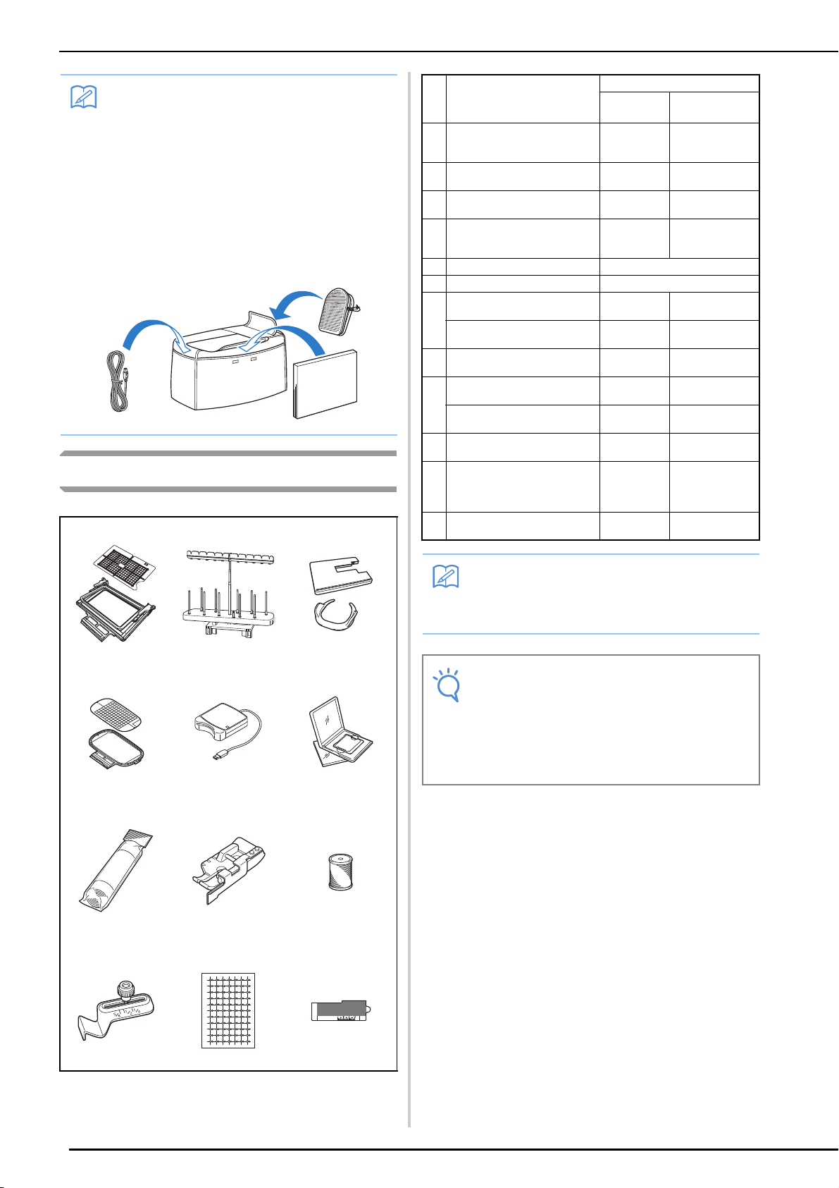
• Included accessories 37, 42, 58 and 59 can
be stored in the machine’s soft cover case.
(In some countries or regions, the soft cover
case is not included in the enclosed accessories; however, it is available as an option.)
Options
123
Part Code
No. Part Name
1 Border embroidery frame set
H 18 cm × W 10 cm
(H 7 inches × W 4 inches)
2 10 spool stand SA560 TS4:
3 Wide table and free motion
grip
4 Embroidery frame set (large)
H 18 cm × W 13 cm
(H 7 inches × W 5 inches)
5 Embroidery card Reader SAECRI
6 Embroidery card –
7 Stabilizer material SA519 BM3:
Water soluble stabilizer SA520 BM5:
8 1/4 quilting foot with guide SA185 F057:
9 Embroidery bobbin thread
(white)
Embroidery bobbin thread
(black)
10 Seam guide SA538 SG1:
11 Embroidery positioning
sticker × 6
(Snowman™ Embroidery
Positioning Marker)
12 Edge sewing sheet × 5 SAESS1 ESS1:
U.S.A./
Canada
SABF6000D BF2:
SATFM6000D
SA439 EF75:
SAEBT EBT-CEN:
SAEBT999 EBT-CEBN:
SAEPS1 EPS1:
Others
XE5059-001
XE5065-001
TFM-3:
XE5062-001
XC8481-052
XE0806-001
XE0615-001
XC7416-252
X81164-001
XC5520-001
XC8483-052
XE5096-001
XE5094-001
456
789
10 11 12
• All specifications are correct at the time of
printing. Please be aware that some specifications may change without notice.
• Embroidery cards purchased in foreign
countries may not work with your machine.
• Visit your nearest authorized dealer for a
complete listing of optional accessories and
embroidery cards available for your
machine.
8
Using the Spool Stand
a
b
CAUTION
Note
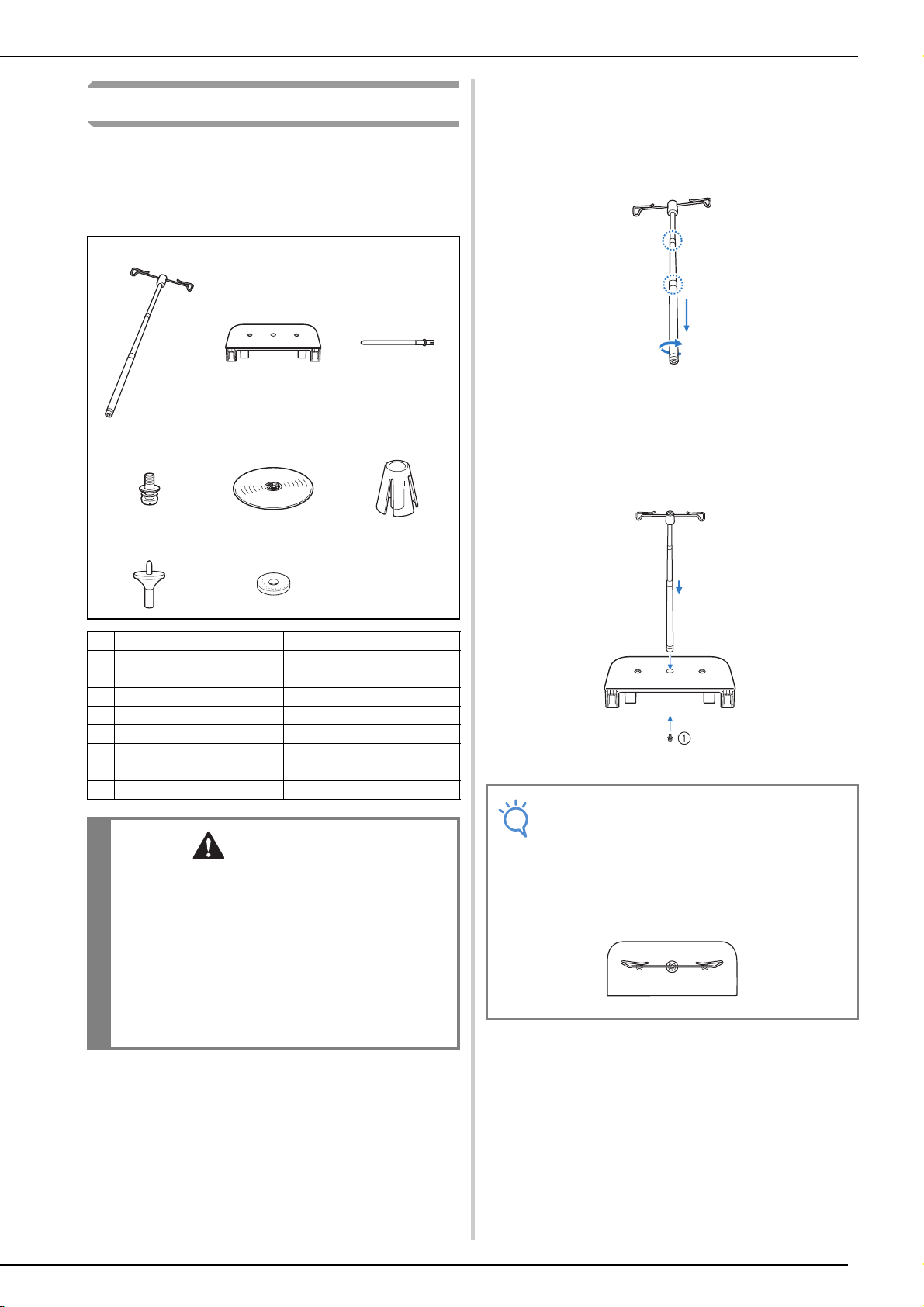
The included spool stand is useful when using
thread spools with a large diameter (cross-wound
thread). The spool stand can hold two spools of
thread.
123
456
NAMES OF MACHINE PARTS AND THEIR FUNCTIONS
■ How to Assemble the Spool Stand
Fully extend the telescopic thread guide
shaft, and then rotate the shaft until the two
internal stoppers click into place.
Insert the telescopic thread guide into the
round hole at the center of the spool
support, and then use a screwdriver to
securely tighten the screw (a) from the
reverse side.
78
No. Part Name Part Code
1 Telescopic thread guide XE0776-001
2 Spool support XE4637-001
3 Spool pin × 2 XA6313-051
4 Screw and washer XC7568-051
5 Spool cap (XL) × 2 XE0779-001
6 Spool holders × 2 XA0679-050
7 Spool cap base × 2 XE0780-001
8 Spool felt × 2 XC7134-051
• Do not lift the handle of the machine while the
spool stand is installed.
• Do not push or pull the telescopic thread
guide or spool pins with extreme force,
otherwise damage may result.
• Do not place any object other than spools of
thread on the spool support.
• Do not try to wind thread on the bobbin while
sewing using the spool stand.
a Screw
• Make sure that the stoppers on the telescopic thread guide shaft are firmly in place
and that the top of the thread guide is
directly above the spool pins. In addition,
check that the shaft is securely tightened in
the spool support.
9
NAMES OF MACHINE PARTS AND THEIR FUNCTIONS
c
d
e
a
b
Memo
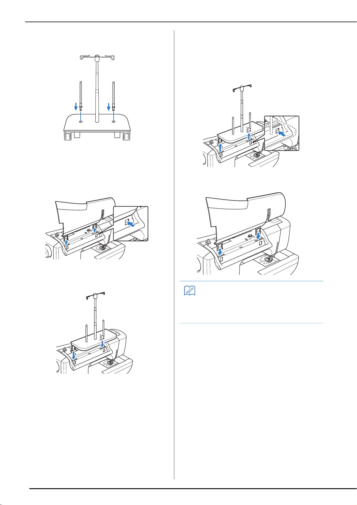
Firmly insert the two spool pins into the two
holes in the spool support.
Open the upper cover of the machine. From
the back of the machine, press in the upper
cover latches (one on each side), and then
pull the upper cover up to remove it from
the machine.
■ How to Remove
From the back of the machine, press in the
spool stand latches (one on each side), and
then pull the spool stand up to remove it
from the machine.
Attach the upper cover to the machine.
Insert the spool stand onto the notches of
the machine.
• See page 41 about the bobbin winding using
the spool stand.
• See page 52 about the upper threading
using the spool stand.
10

Chapter 1
Getting Ready
TURNING THE MACHINE ON/OFF...............12
LCD SCREEN...................................................14
■ Home Page Screen ................................................................... 14
■ Utility Stitch LCD Screen ......................................................... 15
■ Key Functions ...........................................................................16
USB Connectivity.............................................................. 18
■ Using USB Media or Embroidery Card Reader/
USB Card Writer Module*........................................................ 18
■ Connecting the Machine to the Computer ............................... 19
■ Using a USB Mouse ..................................................................19
■ Clicking a Key ..........................................................................20
■ Changing Pages ........................................................................ 20
Using the Machine Setting Mode Key ............................... 22
■ Changing the Pointer Shape When a USB Mouse Is Used ........25
■ Changing the Screen Saver Image ............................................25
■ Selecting the Initial Screen Display ..........................................28
■ Choosing the Display Language................................................ 29
■ Changing the Background Colors
of the Embroidery Patterns.......................................................30
Using the Sewing Machine Help Key ................................ 32
Using the Operation Guide Function................................ 33
Using the Sewing Guide Function..................................... 34
Using the Pattern Explanation Function ............................ 35
LOWER THREADING .....................................37
Winding the Bobbin .......................................................... 37
■ Using the Supplemental Spool Pin............................................37
■ Using the Spool Pin .................................................................. 40
■ Using the Spool Stand .............................................................. 41
■ Untangling Thread from Beneath the Bobbin Winder Seat.......42
Setting the Bobbin ............................................................ 43
Pulling Up the Bobbin Thread........................................... 45
UPPER THREADING.......................................46
Upper Threading............................................................... 46
Using the Twin Needle Mode ........................................... 49
Using the Spool Stand ....................................................... 52
■ Using the Spool Stand .............................................................. 52
Using Threads that Unwind Quickly ................................. 53
■ Using the Spool Net ................................................................. 53
CHANGING THE PRESSER FOOT ..................54
Removing the Presser Foot................................................ 54
Attaching the Presser Foot ................................................ 54
Attaching the Walking Foot .............................................. 55
CHANGING THE NEEDLE..............................56
About the Needle.............................................................. 58
Fabric/Thread/Needle Combinations................................ 58
TURNING THE MACHINE ON/OFF
WARNING
CAUTION
TURNING THE MACHINE ON/OFF
• Use only regular household electricity for the power source. Using other power sources may result in fire,
electric shock, or damage to the machine.
• Make sure that the plugs on the power cord are firmly inserted into the electrical outlet and the power
cord receptacle on the machine.
• Do not insert the plug on the power cord into an electrical outlet that is in poor condition.
• Turn the main power to OFF and remove the plug in the following circumstances:
When you are away from the machine
After using the machine
When the power fails during use
When the machine does not operate correctly due to a bad connection or a disconnection
During electrical storms
• Use only the power cord included with this machine.
• Do not use extension cords or multi-plug adapters with many other appliances plugged in to them. Fire or
electric shock may result.
• Do not touch the plug with wet hands. Electric shock may result.
• When unplugging the machine, always turn the main power to OFF first. Always grasp the plug to remove
it from the outlet. Pulling on the cord may damage the cord, or lead to fire or electric shock.
• Do not allow the power cord to be cut, damaged, modified, forcefully bent, pulled, twisted, or bundled.
Do not place heavy objects on the cord. Do not subject the cord to heat. These things may damage the
cord, or cause fire or electric shock. If the cord or plug is damaged, take the machine to your authorized
dealer for repairs before continuing use.
• Unplug the power cord if the machine is not to be used for a long period of time. Otherwise, a fire may
result.
• When leaving the machine unattended, either the main switch of the machine should be turned to OFF or
the plug must be removed from the socket-outlet.
• When servicing the machine or when removing covers, the machine must be unplugged.
• For U.S.A only
This appliance has a polarized plug (one blade wider than the other). To reduce the risk of electrical
shock, this plug is intended to fit in a polarized outlet only one way.
If the plug does not fit fully in the outlet, reverse the plug. If it still does not fit, contact a qualified
electrician to install the proper outlet. Do not modify the plug in any way.
12
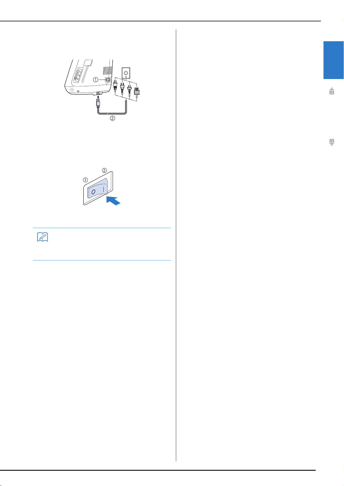
a
Insert the power supply cord into the power
b
c
Memo
cord receptacle, then insert the plug into a
wall outlet.
a Main power switch
b Power supply cord
Turn the main power switch to “I” to turn
on the machine.
TURNING THE MACHINE ON/OFF
1
Getting Ready
a OFF
b ON
• When the machine is turned on, the needle
and the feed dogs will make sound when
they move; this is not a malfunction.
Turn the main power switch to “O” to turn
off the machine.
13
LCD SCREEN
Note
Memo
LCD SCREEN
When the machine is turned on, the opening movie is played. Touch anywhere on the screen for the
home page screen to be displayed. Touch the LCD screen or a key with your finger or the included touch
pen to select a machine function.
• When the straight stitch needle plate is on the machine, the needle will automatically move to the middle position.
• Only touch the screen with your finger or the included touch pen. Do not use a sharp pencil, screwdriver, or other hard or sharp object. It is not necessary to press hard on the screen. Pressing too hard
or using a sharp object may damage the screen.
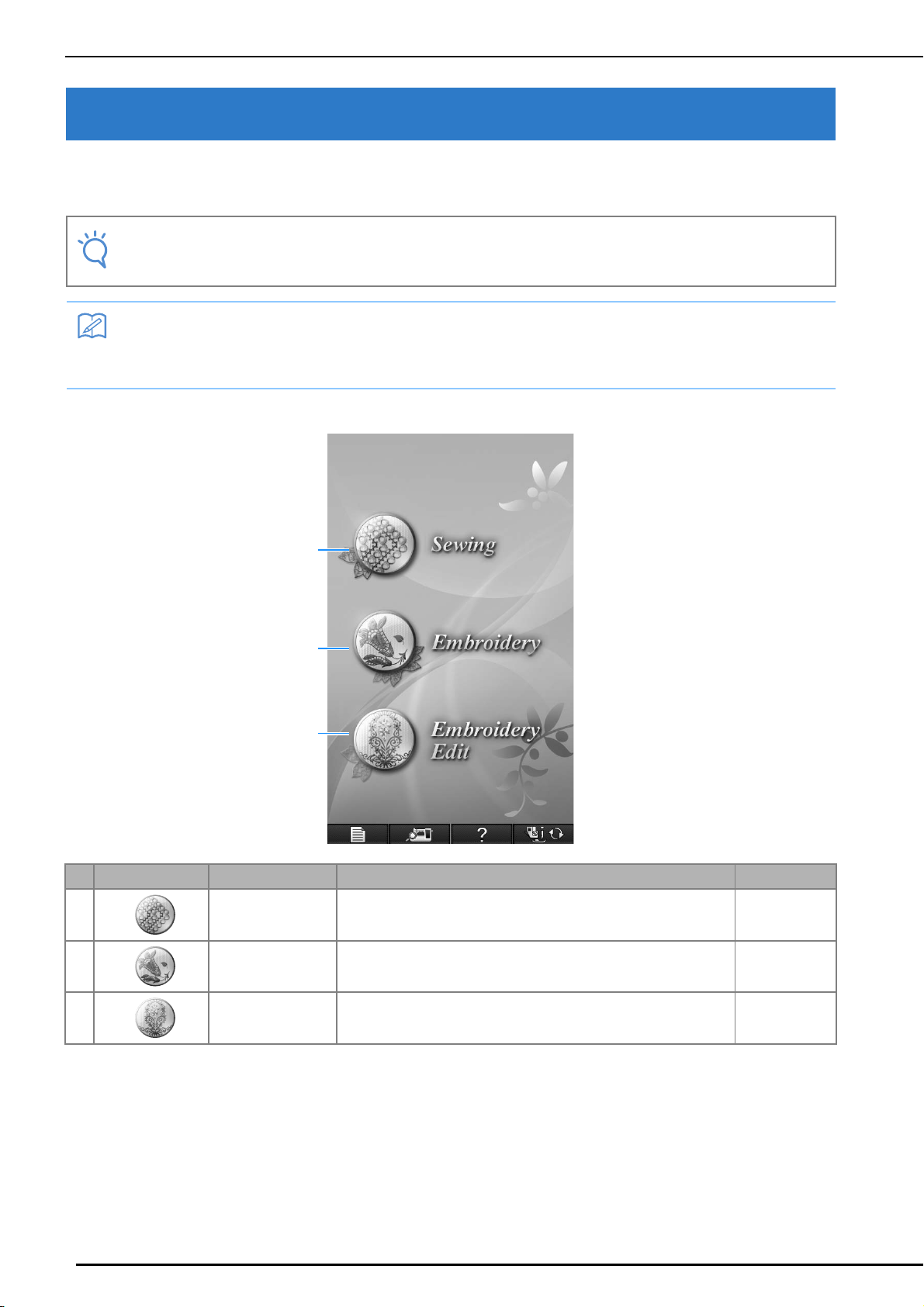
■ Home Page Screen
a
b
c
No. Display Key Name Explanation Page
a Sewing key Press this key to sew utility stitches or character or decorative stitch
patterns.
b Embroidery key Attach the embroidery unit and press this key to embroider patterns. 182
See the “Key
Functions” table.
16
c Embroidery Edit key Press this key to combine embroidery patterns. With the embroidery
14
edit functions, you can also create original embroidery patterns or frame
patterns.
262
LCD SCREEN
a
b
c
d
e
f
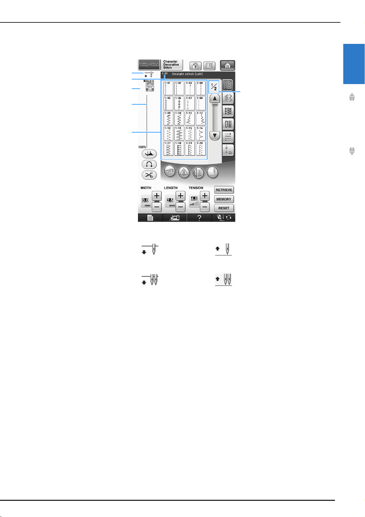
■ Utility Stitch LCD Screen
Press a key with your finger to select the stitch pattern, to select a machine function, or to select an
operation indicated on the key.
1
Getting Ready
a Shows single or twin needle mode setting, and the needle stop position.
Single needle/down position Single needle/up position
Twin needle/down position Twin needle/up position
b Shows the name and code number of the selected stitch.
c Shows the presser foot code. Attach the presser foot indicated in this display before sewing.
d Shows a preview of the selected stitch.
When shown at 100%, the stitch appears in the screen at nearly its actual size.
e Shows the stitch patterns.
f Shows additional pages that can be displayed (Illustration shows page 1 of 2.).
* All key functions of the LCD are explained in the “Key Functions” table on the following page.
15
LCD SCREEN
a
b e
f
g
h
i
j
k
l
mno
v
q
s
p
u
r
t
cxd
w
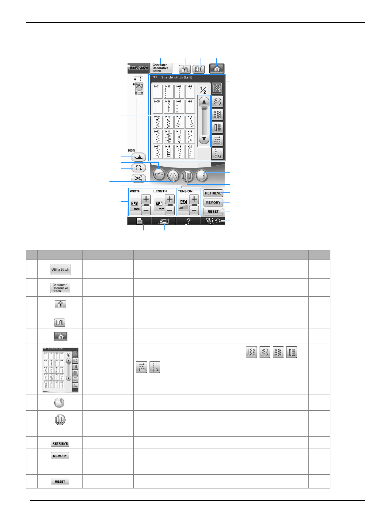
■ Key Functions
No. Display Key Name Explanation Page
a Utility stitch key Press this key to select a straight stitch, zigzag stitch, buttonhole, blind hem
b Character/Decorative
c Screen lock key Press this key to lock the screen.When the screen is locked, the various
d Image key Press this key to display an enlarged image of the selected stitch pattern. 80
e Home page screen
f Stitch selection
g Edge sewing key Using the built-in camera, press this key to measure the width of the area from
h Needle mode
stitch key
key
display
selection key (single/
double)
i Retrieve key Press this key to retrieve a saved pattern. 82
j Manual memory key Change the stitch pattern settings (zigzag width and stitch length, thread
k Reset key Press this key to return the selected stitch pattern saved settings to the default
stitch, or other stitches commonly used in garment construction.
Press this key to select character or decorative stitch patterns. 146
settings, such as the stitch width and stitch length, are locked and cannot be
changed. Press this key again to unlock the settings.
Press this key anytime it is displayed to return to the home page screen and
select a different category - “Sewing”, “Embroidery” or “Embroidery edit”.
Press the key for the pattern you want to sew. Use
to change to different stitch groups.
the edge of the fabric to the stitch and set the camera for edge sewing.
Press this key to select twin needle sewing mode. The sewing mode changes
between single needle mode and twin needle mode each time you press the
key. If the key display is light gray, the selected stitch pattern cannot be sewn in
the twin needle mode.
tension, automatic thread cutting or automatic reinforcement stitching, etc.),
then save them by pressing this key. Five sets of settings can be saved for a
single stitch pattern.
settings.
16
79
74
14
79
138
49
81
66-67
 Loading...