


Installation and Operation Manual
X-VA-MT3809-3819-eng Part Number: 541B049AHG September, 2008
Models MT 3809 & 3819
Brooks® Model MT 3809 and 3819 Metal Tube Variable Area Flowmeters
with Optional Electronics Based on Smart Meter ManagerTM Technology
Model MT 3809
Models MT 3809 & 3819
Installation and Operation Manual
X-VA-MT3809-3819-eng Part Number: 541B049AHG September, 2008
Essential Instructions
Read this page before proceeding!
Brooks Instrument designs, manufactures and tests its products to meet many national and international standards. Because these instruments are sophisticated technical products, you must properly install, use and maintain them to ensure they continue to operate within their normal specifications. The following instructions must be adhered to and integrated into your safety program when installing, using and maintaining Brooks Products.
•Read all instructions prior to installing, operating and servicing the product. If this instruction manual is not the correct manual, please see back cover for local sales office contact information. Save this instruction manual for future reference.
•If you do not understand any of the instructions, contact your Brooks Instrument representative for clarification.
•Follow all warnings, cautions and instructions marked on and supplied with the product.
•Inform and educate your personnel in the proper installation, operation and maintenance of the product.
•Install your equipment as specified in the installation instructions of the appropriate instruction manual and per applicable local and national codes. Connect all products to the proper electrical and pressure sources.
•To ensure proper performance, use qualified personnel to install, operate, update, program and maintain the product.
•When replacement parts are required, ensure that qualified people use replacement parts specified by Brooks Instrument. Unauthorized parts and procedures can affect the product's performance and place the safe operation of your process at risk. Look-alike substitutions may result in fire, electrical hazards or improper operation.
•Ensure that all equipment doors are closed and protective covers are in place, except when maintenance is being performed by qualified persons, to prevent electrical shock and personal injury.
Pressure Equipment Directive (PED)
All pressure equipment with an internal pressure greater than 0.5 bar (g) and a size larger than 25mm or 1" (inch) falls under the Pressure Equipment Directive (PED). The Directive is applicable within the European Economic Area (EU plus Norway, Iceland and Liechtenstein). Pressure equipment can be traded freely within this area once the PED has been complied with.
•Section 1 of this manual contains important safety and operating instructions related to the PED directive.
•Meters described in this manual are in compliance with EN directive 97/23/EC module H Conformity Assessment.
•All Brooks Instrument Flowmeters fall under fluid group 1.
•Meters larger than 25mm or 1" (inch) are in compliance with category I, II, III of PED.
•Meters of 25mm or 1" (inch) or smaller are Sound Engineering Practice (SEP).
ESD (Electrostatic Discharge)
Handling Procedure:
1.Power to unit must be removed.
2.Personnel must be grounded, via a wrist strap or other safe, suitable means before any printed circuit card or other internal device is installed, removed or adjusted.
3.Printed circuit cards must be transported in a conductive container. Boards must not be removed from protective enclosure until immediately before installation. Removed boards must immediately be placed in protective container for transport, storage or return to factory.
Comments
This instrument is not unique in its content of ESD (electrostatic discharge) sensitive components. Most modern electronic designs contain components that utilize metal oxide technology (NMOS, SMOS, etc.). Experience has proven that even small amounts of static electricity can damage or destroy these devices. Damaged components, even though they appear to function properly, exhibit early failure.

Installation and Operation Manual
X-VA-MT3809-3819-eng Part Number: 541B049AHG September, 2008
Models MT 3809 & 3819
Dear Customer,
We appreciate this opportunity to service your flow measurement and control requirements with a Brooks Instrument device. Every day, flow customers all over the world turn to Brooks Instrument for solutions to their gas and liquid low-flow applications. Brooks provides an array of flow measurement and control products for various industries from biopharmaceuticals, oil and gas, fuel cell research and chemicals, to medical devices, analytical instrumentation, semiconductor manufacturing, and more.
The Brooks product you have just received is of the highest quality available, offering superior performance, reliability and value to the user. It is designed with the ever changing process conditions, accuracy requirements and hostile process environments in mind to provide you with a lifetime of dependable service.
We recommend that you read this manual in its entirety. Should you require any additional information concerning Brooks products and services, please contact your local Brooks Sales and Service Office listed on the back cover of this manual or visit www.BrooksInstrument.com
Yours sincerely,
Brooks Instrument

Models MT 3809 & 3819
Installation and Operation Manual
X-VA-MT3809-3819-eng Part Number: 541B049AHG September, 2008
THIS PAGE WAS
INTENTIONALLY
LEFT BLANK

Installation and Operation Manual
X-VA-MT3809-3819-eng Part Number: 541B049AHG September, 2008
Contents
Models MT 3809 & 3819
Section 1 Introduction |
|
|
Paragraph |
Page |
|
Number |
Number |
|
1-1 |
Description ....................................................................................................................................... |
1-1 |
1-2 |
Design Features ............................................................................................................................... |
1-1 |
1-3 |
Specifications - Meter ....................................................................................................................... |
1-1 |
1-4 |
Optional Accessories ........................................................................................................................ |
1-7 |
1-5 |
Optional Electronic Equipment ......................................................................................................... |
1-7 |
1-6 Microprocessor Transmitter With or Without Alarms and Pulse Output |
|
|
|
Based on Brooks Smart Meter Management Technology ................................................................ |
1-7 |
1-7 |
Microprocessor Transmitter With Inductive Alarms ......................................................................... |
1-16 |
1-8 |
Inductive Alarm Switches ................................................................................................................ |
1-18 |
Section 2 Installation |
|
|
2-1 |
General ............................................................................................................................................. |
2-1 |
2-2 |
Receipt of Equipment ....................................................................................................................... |
2-1 |
2-3 |
Recommended Storage Practice...................................................................................................... |
2-1 |
2-4 |
Return Shipment .............................................................................................................................. |
2-2 |
2-5 |
Transit Precautions .......................................................................................................................... |
2-2 |
2-6 |
Removal from Storage...................................................................................................................... |
2-2 |
2-7 |
Installation of Flowmeter .................................................................................................................. |
2-3 |
2-8 Installation of Models Model MT 3809 and MT 3819 Flowmeters with a Smart Meter Manager |
||
|
Transmitter with or without Optional Alarms and Pulse Output ........................................................ |
2-4 |
2-9 Installation of Models Model MT 3809 and MT 3819 Flowmeters with a Smart Meter Manager |
||
|
Transmitter with Inductive Alarms (1 or 2 Switches) ........................................................................ |
2-10 |
2-10 Installation of Models Model MT 3809 and MT 3819 Flowmeters with Inductive Alarms |
|
|
|
(1 or 2 Switches) ............................................................................................................................. |
2-10 |
Section 3 Operation |
|
|
3-1 |
Pre-Start Check ................................................................................................................................ |
3-1 |
3-2 Start-Up and Operation of Flowmeter ............................................................................................... |
3-1 |
|
3-3 Operation of Models Model MT 3809 and MT 3819 Flowmeters with a Smart Meter Manager |
||
|
Transmitter with or without Optional Alarms and Pulse Output for Totalization ................................ |
3-2 |
3-4 Operation of Models Model MT 3809 and MT 3819 Flowmeters with a Smart Meter Manager |
||
|
Transmitter with Inductive Alarms (1 or 2 Switches) ........................................................................ |
3-13 |
3-5 Operation of Models Model MT 3809 and MT 3819 Flowmeters with |
|
|
|
with Inductive Alarms (1 or 2 Switches) ........................................................................................... |
3-13 |
Section 4 Maintenance |
|
|
4-1 |
General Service Information ............................................................................................................. |
4-1 |
4-2a Meter Float Replacement and Cleaning (MT 3809).......................................................................... |
4-2 |
|
4-2b Meter Float Replacement and Cleaning (MT 3819).......................................................................... |
4-8 |
|
4-3 Meter Indicator Reference Mark (Zero) Adjustment ......................................................................... |
4-8 |
|
4-4 Smart Meter Manager Transmitter Replacement with or without Alarms and Pulse Output ............. |
4-8 |
|
4-5 |
Inductive Alarm Replacement ........................................................................................................... |
4-8 |
4-6 SMM Transmitter Replacement with Inductive Alarms .................................................................... |
4-10 |
|
4-7 Monitoring the Integrity of the SMM Electronics - Diagnostics Alarms ............................................ |
4-10 |
|
Section A CE Certification |
|
|
|
CE Certification of Mass Flow Equipment ........................................................................................ |
A-1 |
Warranty, Local Sales/Service Contact Information....................................................................... |
Back Cover |
|
i

Contents |
Installation and Operation Manual |
Models MT 3809 & 3819
X-VA-MT3809-3819-eng Part Number: 541B049AHG September, 2008
Figures |
|
|
Figure |
Page |
|
Number |
Number |
|
1-1 |
Models MT 3809 and MT 3819 Dimensions ..................................................................................... |
1-6 |
1-2 |
Power Supply vs. Maximum Load Resistance ................................................................................. |
1-9 |
1-3 |
Transmitter Only Wiring Diagram .................................................................................................... |
1-11 |
1-4 |
Transmitter Only Wiring Notes ........................................................................................................ |
1-12 |
1-5 |
Transmitter with Alarm and Pulse Outputs Wiring Diagram ............................................................ |
1-13 |
1-6 |
Transmitter with Alarm and Pulse Outputs Wiring Notes ................................................................ |
1-14 |
1-7 |
Model MT3809 Explosion-Proof Housing Wiring Diagram .............................................................. |
1-15 |
1-8 |
Transmitter with Inductive Alarm Wiring Diagram ........................................................................... |
1-16 |
1-9 |
Transmitter with Inductive Alarm Wiring Notes................................................................................ |
1-17 |
1-10 Inductive Alarms Only Wiring Diagram ............................................................................................ |
1-20 |
|
1-11 |
Inductive Alarms Only Wiring Notes ................................................................................................ |
1-21 |
2-1 |
Typical Bypass Installation................................................................................................................ |
2-3 |
2-2 |
Smart Meter Manager Electrical Configuration................................................................................. |
2-5 |
2-3 |
Typical SMM Transmitter Analog Output and Power Wiring ............................................................. |
2-5 |
2-4 |
Alternate SMM Transmitter Analog Output and Power Wiring (Where 4-20 mA is not required) ..... |
2-6 |
2-5 |
Multi-drop SMM Transmitter Analog Output and Power Wiring ........................................................ |
2-6 |
2-6 |
Typical SMM Transmitter with Alarms and Pulse Digital Output and Power Wiring.......................... |
2-8 |
3-1 |
Models MT 3809 and MT 3819 SMM Electronics Device Description Tree (Basic Setup) ............... |
3-3 |
3-2 |
Models MT 3809 and MT 3819 SMM Electronics Device Description Tree (Detailed Setup) ........... |
3-4 |
3-3 |
HART Communicator ....................................................................................................................... |
3-5 |
3-4 |
Typical HART Communicator Interface ............................................................................................ |
3-5 |
3-5 |
HART Communicator Action / Hot Keys ........................................................................................... |
3-6 |
3-6 |
HART LCD ....................................................................................................................................... |
3-6 |
4-1 |
Meter Float Replacement & Cleaning (Model MT 3809) .................................................................. |
4-6 |
4-2 |
Exploded View, Model MT 3809, Size 15 (Gas or Liquid Service) .................................................... |
4-7 |
4-3 |
Exploded View, Model MT 3809, Size 16 (Liquid Service Only) ....................................................... |
4-7 |
4-4 |
Meter Float Replacement & Cleaning (Model MT 3819) .................................................................. |
4-9 |
Tables |
|
|
Table |
|
Page |
Number |
Number |
|
1-1A Model MT 3809 Capacities, Pressure Drop and Viscosity Immunity Ceiling .................................... |
1-4 |
|
1-1B Model MT 3819 (Tefzel Lined)Capacities and Pressure Drop .......................................................... |
1-4 |
|
1-2 |
Model MT 3809 Pressure Ratings* ................................................................................................... |
1-5 |
1-3 |
Maximum Fluid Temperatures at 104oF (40oC) Ambient .................................................................. |
1-5 |
ii

Installation and Operation Manual |
Section 1 Introduction |
X-VA-MT3809-3819-eng Part Number: 541B049AHG September, 2008
Models MT 3809 & 3819
1-1 Description
The Brooks® Models MT 3809 and MT 3819 Variable Area Flowmeters are rugged, all metal flowmeters offering 2% full scale accuracy. The Model MT 3809 is constructed with stainless steel components for measuring a variety of gas, liquid and steam applications while the Model MT 3819 utilizes a ETFE (Tefzel™) lining for aggressive liquid and gas applications. Flow rate indication is provided by means of magnetic coupling where a magnet, encapsulated in the float, is coupled to a rotatable magnet located in the rear of the indicator, thus turning the dial indicator mounted on the meter.
Optional accessories available include 4-20 mA output with HART microprocessor transmitter with or without configurable alarms and pulse output for totalization. The microprocessor electronics are based on the proprietary Smart Meter Manager technology utilized as the basis for an array of Brooks products.
Also available are front adjustable inductive alarms, high temperature or stainless steel indicator housings, valves, sight flows, flow controllers and material certifications.
1-2 Design Features
•Broad range of flow capacities
•2% Full scale accuracy
•Versatile construction for all gas, liquid, steam applications
•Operable under high temperatures and pressures
•Flanged or female NPT connections
•Optional 4-20mA and HART® programmable
microprocessor transmitter with or without alarms and pulse output for totalization
•Electronics designed with either intrinsically safe or explosion proof construction to meet UL, (US & Canada) ATEX certifications and CE requirements
1-3 Specifications - Meter
 WARNING
Do not operate this instrument in excess of the specifications listed below. Failure to heed this warning can result in serious personal injury and/or damage to the equipment.
Capacities, Pressure Drop and Viscosity Immunity
Ceiling
Refer to Tables 1-1A and 1-1B
Accuracy
Standard Flow Accuracy: ± 2% Full Scale
Optional Flow Accuracy: ± 1% Full Scale
1-1

Section 1 Introduction |
Installation and Operation Manual |
Models MT 3809 & 3819
X-VA-MT3809-3819-eng Part Number: 541B049AHG September, 2008
Repeatability
0.25% Full Scale
Pressure Ratings
Refer to Table 1-2 for Model MT 3809 maximum non-shock pressure. Model MT 3819 pressure rating is dependant on flange rating.
Pressure Equipment Directive (PED) 97/23/EC
Flow meter complies under Sound Engineering
Practices (SEP) or Catagories I, II or III
Scales
Standard: Detachable aluminum plate (Single or dual scales) Graduations: Choice of direct reading units, percentage of maximum flow
Operating Fluid Temperature Limits (Meter only)
Minimum MT 3809 and MT 3819: -20°F (-29°C) Maximum:
Standard MT 3809: 420°F(215°C)
Standard MT 3809 with Valve: 392°F(200°C) Standard MT 3819: 302°F (150°C)
Refer to Table 1-3 for temperature limitations for meters with electronics.
Materials of Construction:
Metering Tube
MT 3809 Standard: 316L stainless steel
MT 3809 Optional: Inconnel 625™, Hastelloy B™, Hastelloy C™, titanium
MT 3819 Standard: 316L stainless steel with ETFE (Tefzel) lining
1-2

Installation and Operation Manual |
Section 1 Introduction |
X-VA-MT3809-3819-eng Part Number: 541B049AHG September, 2008
Models MT 3809 & 3819
Flanges and End Fittings
MT 3809 Standard: 316/316L stainless steel dual certified MT 3809 Optional: Hastelloy B, Hastelloy C, titanium
MT 3819 Standard: 316L stainless steel
Connections
MT 3809 Standard:
150 lbs, 300 lbs or 600 lbs RF ANSI B 16.5 flanges or PN 40 DIN 2527/ 2635; or JIS flanges 10K or 20K; or Female NPT, Male NPT for No O-ring meter only
125/250 Ra micro inch (3.2/6.3 Ra micro meter) cerated flange finish. Consult factory for optional uncerated flange finish.
Vertical inlet and outlet
MT 3819 Standard:
150 lbs RF ANSI B 16.5 flanges or PN 40 DIN 2527/2635 MT 3819 Optional:
300 lbs RF ANSI B 16.5 flanges or PN 40 DIN 2527/2635. For other ratings/flange types consult factory.
125/250 Ra micro inch (3.2/6.3 Ra micro meter) cerated flange finish. Consult factory for optional uncerated flange finish.
Vertical inlet and outlet
Floats
MT 3809 Standard: 316L stainless steel
MT 3809 Optional: Inconnel 625, Hastelloy C or titanium
MT 3819 Standard: Hastelloy C, Sizes 7 and 8, PVDF Sizes 10, 12 and 13. MT 3819 Optional: Inconnel 625 or titanium all sizes; all Teflon® internals Sizes 10, 12 and 13.
O-rings (NPT only)
MT 3809 Standard: Viton® fluoroelastomers
MT 3809 Optional: Teflon, none with male NPT connections
MT 3819: None
Indicator Housing and Cover
Enclosure NEMA 4X construction
MT 3809 and MT 3819 Standard Housing: Die cast aluminum, polyurethane paint with glass window
MT 3809 and MT 3819 Optional Housing: 316L stainless steel with gritblast and glass window; epoxy paint for aluminum housing
Meter Dimensions
Refer to Figure 1-1
1-3

Section 1 Introduction |
Installation and Operation Manual |
Models MT 3809 & 3819
X-VA-MT3809-3819-eng Part Number: 541B049AHG September, 2008
Table 1-1A Model MT 3809 Capacities, Pressure Drop and Viscosity Immunity Ceiling
|
CONNECTION SIZE |
|
|
|
FLOAT MATERIAL STAINLESS STEEL 316L |
|
|
|
|||||
METER |
DIN |
ANSI |
FLOAT |
WATER |
|
AIR 1,2 |
Press Drop |
Press Drop |
VIC (cSt) |
Max. Visc |
PED |
||
SIZE |
DN mm |
inches |
CODE |
l/h |
gpm |
scfm |
|
nm3/h |
mbar |
inches WC |
(cSt) |
(cSt) |
Category |
|
15 |
1/2" |
A |
25 |
0.11 |
0.49 |
|
0.78 |
30 |
13 |
1 |
40 |
SEP |
7 |
|
|
B* |
65 |
0.28 |
1.2 |
|
2 |
30 |
13 |
1 |
20 |
SEP |
|
|
C |
130 |
0.59 |
2.4 |
|
3.7 |
30 |
13 |
1 |
120 |
SEP |
|
|
|
|
|
||||||||||
|
|
|
D* |
200 |
0.88 |
3.7 |
|
5.8 |
35 |
15 |
1 |
20 |
SEP |
|
15 |
1/2" |
A |
250 |
1.1 |
5.2 |
|
8.2 |
45 |
19 |
2 |
250 |
SEP |
8 |
|
|
B |
400 |
1.7 |
7.7 |
|
12 |
55 |
23 |
1 |
180 |
SEP |
|
|
C |
650 |
2.8 |
11 |
|
18 |
60 |
25 |
2 |
475 |
SEP |
|
|
|
|
|
||||||||||
|
|
|
D |
1000 |
4.4 |
21 |
|
33 |
130 |
53 |
1.5 |
250 |
SEP |
|
25 |
1" |
A |
1200 |
5.2 |
19 |
|
30 |
60 |
25 |
5 |
475 |
CAT I, II or III |
10 |
|
|
B |
1500 |
6.6 |
31 |
|
49 |
70 |
29 |
1.5 |
400 |
CAT I, II or III |
|
|
C |
2400 |
10 |
41 |
|
65 |
85 |
35 |
7 |
475 |
CAT I, II or III |
|
|
|
|
|
||||||||||
|
|
|
D |
3500 |
15 |
65 |
|
100 |
155 |
63 |
4 |
475 |
CAT I, II or III |
|
40 |
1 1/2" |
A |
4000 |
17 |
67 |
|
100 |
50 |
21 |
50 |
475 |
CAT I, II or III |
12 |
|
|
B |
6000 |
26 |
94 |
|
140 |
60 |
25 |
30 |
475 |
CAT I, II or III |
|
|
C |
8000 |
35 |
150 |
|
230 |
150 |
61 |
2 |
475 |
CAT I, II or III |
|
|
|
|
|
||||||||||
|
|
|
D |
10000 |
46 |
210 |
|
330 |
300 |
121 |
2 |
475 |
CAT I, II or III |
|
50 |
2" |
A |
6500 |
28 |
100 |
|
160 |
50 |
21 |
50 |
475 |
CAT I, II or III |
13 |
|
|
B |
9500 |
41 |
160 |
|
250 |
60 |
25 |
50 |
475 |
CAT I, II or III |
|
|
C |
12000 |
55 |
200 |
|
310 |
100 |
41 |
2.5 |
475 |
CAT I, II or III |
|
|
|
|
|
||||||||||
|
|
|
D |
20000 |
88 |
390 |
|
620 |
300 |
121 |
1 |
475 |
CAT I, II or III |
15 |
80 |
3" |
A |
20000 |
88 |
390 |
|
620 |
110 |
45 |
8 |
475 |
CAT I, II or III |
|
|
B |
30000 |
130 |
550 |
|
860 |
140 |
57 |
7 |
475 |
CAT I, II or III |
|
|
|
|
C |
40000 |
170 |
750 |
|
1100 |
280 |
113 |
5 |
475 |
CAT I, II or III |
16 |
100 |
4" |
A |
49000 |
210 |
NA |
|
NA |
160 |
65 |
15 |
475 |
CAT I, II or III |
|
|
B |
70000 |
300 |
NA |
|
NA |
210 |
85 |
10 |
475 |
CAT I, II or III |
|
|
|
|
C |
100000 |
440 |
NA |
|
NA |
300 |
121 |
5 |
475 |
CAT I, II or III |
1.Air flows in scfm are given at 70°F and 14.7 psia
2.Air flows in nm3/h are given at 0°C and 1.013 bar (a)
3.*Minimum operating pressure required 7 psig / 0.48 bar
Table 1-1B Model MT 3819 (Tefzel Lined) Capacities and Pressure Drop
|
CONNECTION SIZE |
TUBE |
STANDARD FLOAT MATERIAL CAPACITIES (See Note 3) |
|
||||||
METER |
DIN |
ANSI |
FLOAT |
WATER |
AIR 1,2,4 |
Press Drop |
Press Drop |
PED |
||
SIZE |
DN mm |
inches |
CODE |
l/h |
gpm |
scfm |
nm3/h |
mbar |
inches WC |
Category |
7 |
15 |
1/2" |
GA |
110 |
0.48 |
2 |
3.2 |
25 |
11 |
SEP |
|
|
GB |
170 |
0.75 |
3.2 |
5 |
50 |
21 |
SEP |
|
|
|
|
||||||||
|
15 |
1/2" |
A |
250 |
1.1 |
4.6 |
7.3 |
30 |
13 |
SEP |
8 |
|
|
B |
420 |
1.8 |
7.7 |
12 |
45 |
19 |
SEP |
|
|
C |
500 |
2.2 |
9.2 |
14 |
40 |
17 |
SEP |
|
|
|
|
||||||||
|
|
|
D |
850 |
3.7 |
15 |
24 |
130 |
53 |
SEP |
|
25 |
1" |
A |
1400 |
6.2 |
26 |
41 |
45 |
19 |
CAT I, II or III |
10 |
|
|
B |
2000 |
8.8 |
37 |
58 |
106 |
43 |
CAT I, II or III |
|
|
C |
2400 |
10 |
44 |
70 |
90 |
37 |
CAT I, II or III |
|
|
|
|
||||||||
|
|
|
D |
3000 |
13 |
55 |
87 |
130 |
53 |
CAT I, II or III |
|
40 |
1 1/2" |
A |
3000 |
13 |
55 |
87 |
50 |
21 |
CAT I, II or III |
12 |
|
|
B |
4000 |
18 |
74 |
110 |
75 |
31 |
CAT I, II or III |
|
|
C |
5000 |
22 |
92 |
140 |
85 |
35 |
CAT I, II or III |
|
|
|
|
||||||||
|
|
|
D |
6000 |
26 |
110 |
170 |
120 |
49 |
CAT I, II or III |
|
50 |
2" |
A |
6000 |
26 |
110 |
170 |
95 |
39 |
CAT I, II or III |
13 |
|
|
B |
8000 |
35 |
147 |
230 |
125 |
51 |
CAT I, II or III |
|
|
C |
12000 |
53 |
220 |
340 |
200 |
81 |
CAT I, II or III |
|
|
|
|
||||||||
|
|
|
D |
15000 |
66 |
270 |
430 |
225 |
91 |
CAT I, II or III |
1.Air flows in scfm are given at 70°F and 14.7 psia
2.Air flows in nm3/h are given at 0°C and 1.013 bar (a)
3.Sizes 7 & 8 floats are Hastelloy C-276 (Density = 8.94 kg/dm3), Sizes 10, 12 & 13 are PVDF (Density = 4.22 kg/dm3)
4.For gas applications operating pressure must be greater than 29 PSIA / 2 bar (a)
1-4
Installation and Operation Manual |
Section 1 Introduction |
X-VA-MT3809-3819-eng Part Number: 541B049AHG September, 2008
Models MT 3809 & 3819
Table 1-2 Model MT 3809 Pressure Ratings*
|
|
316/316L Stainless Steel (psig at indicated temperature) |
|
||||
Flange Rating** |
|
|
|
|
|
|
|
-20°F to 100°F |
200°F |
300°F |
400°F |
500°F |
600°F |
617°F |
|
150 lb. |
275 |
240 |
215 |
195 |
170 |
140 |
134 |
300 lb. |
720 |
620 |
560 |
515 |
480 |
450 |
448 |
600 lb. |
1440 |
1240 |
1120 |
1030 |
955 |
905 |
899 |
|
|
|
|
|
|
|
|
|
|
|
|
|
|
|
|
|
|
316L Stainless Steel (psig at indicated temperature) |
|
||||
Threaded NPT |
|
|
|
|
|
|
|
-20°F to 100°F |
200°F |
300°F |
400°F |
500°F |
600°F |
617°F |
|
7 & 8 |
1500 |
1500 |
1400 |
1400 |
1300 |
1200 |
1200 |
10 |
1500 |
1500 |
1400 |
1400 |
1300 |
1200 |
1200 |
12 |
1500 |
1500 |
1400 |
1400 |
1300 |
1200 |
1200 |
13 |
1300 |
1300 |
1200 |
1200 |
1100 |
1000 |
1000 |
* Model MT 3819 pressure ratings dependent on flange rating. **Flanges are dual certified 316L/316 stainless steel.
Table 1-3 Maximum Fluid Temperatures at 104°F (40°C) Ambient
3809 |
Indicator Only |
Indicator with Alarm1 |
Indicator with Transmitter1 |
||||
Size |
Standard |
High Temperature |
Standard |
High Temperature |
Standard |
High Temperature |
|
7 & 8 |
-58° thru 420° F |
617° F |
-22° thru 320° F |
450° F |
-22° thru 195° F |
300° F |
|
-50° thru 215° C |
325° C |
-30° thru 160° C |
230° C |
-30° thru 90° C |
150° C |
||
|
|||||||
10 thru 16 |
-58° thru 420° F |
617° F |
-22° thru 320° F |
617° F |
-22° thru 195° F |
400° F |
|
-50° thru 215° C |
325° C |
-30° thru 160° C |
325° C |
-30° thru 90° C |
200° C |
||
|
|||||||
|
|
|
|
||||
3819 |
Indicator Only |
Indicator with Alarm1 |
Indicator with Transmitter1 |
||||
Size |
Standard |
High Temperature |
Standard |
High Temperature |
Standard |
High Temperature |
|
7 thru 13 |
-22° thru 300° F |
300° F |
-22° thru 300° F |
300° F |
-22° thru 195° F |
300° F |
|
-30° thru 150° C |
150° C |
-30° thru 150° C |
150° C |
-30° thru 90° C |
150° C |
||
|
|||||||
309 &3819 Minimum and Maximum Ambient Temperature
Indicator Only2 |
Indicator with Alarm or Transmitter |
-58° thru 150° F |
-22° thru 150° F |
-50° thru 65° C |
-30° thru 65° C |
1.High Temperature option not available with Explosion Proof Housing
2.Ambient Temperature below -22° F / -30° C requires Low Ambient Temperature Option
1-5
Section 1 Introduction |
Installation and Operation Manual |
Models MT 3809 & 3819
X-VA-MT3809-3819-eng Part Number: 541B049AHG September, 2008
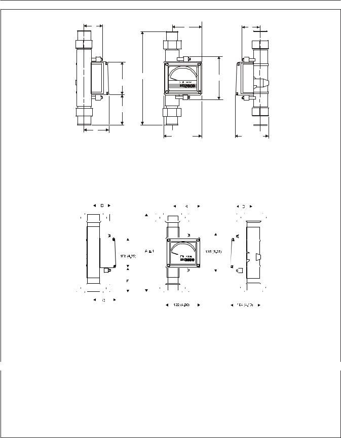
Model MT 3809 with NPT-F Connections mm (inches)*
D |
B |
D |
|
A ± 2 |
135 (5.31) |
|
108 (4.25) |
|
|
E |
|
C |
122 (4.80) |
104 (4.10) |
|
Meter Size |
Connection |
A |
B |
C |
D |
E |
WEIGHT (Approx.)** |
7 & 8 |
1/2" NPT-F |
225 (8.85) |
88 (3.46) |
72 (2.83) |
53 (2.09) |
59 (2.32) |
1.3 kg (3 lbs.) |
10 |
1" NPT-F |
300 (11.81) |
95 (3.78) |
80 (3.15) |
59 (2.32) |
96 (3.78) |
2.8 kg (7 lbs.) |
12 |
1-1/2" NPT-F |
300 (11.81) |
105 (4.13) |
89 (3.50) |
65 (2.56) |
96 (3.78) |
5 kg. (12 lbs.) |
13 |
2" NPT-F |
300 (11.81) |
111 (4.37) |
95 (3.74) |
77 ( 3.63) |
96 (3.78) |
6.3 kg (14 lbs.) |
|
|
|
|
|
|
|
|
Models MT 3809 and MT 3819 with Flanged Connections mm (inches)*
|
|
|
|
|
|
|
|
|
|
|
|
|
|
|
|
|
|
|
|
|
|
|
|
|
|
|
|
|
|
|
|
|
|
|
|
|
|
|
|
|
|
|
|
|
|
|
|
|
|
|
|
|
|
|
|
|
|
|
|
|
|
|
|
|
|
|
|
|
|
|
|
|
|
|
|
|
|
|
|
|
|
|
|
|
|
|
|
|
|
|
|
|
|
|
|
|
|
|
|
|
|
|
|
|
|
|
|
|
|
|
|
|
|
|
|
|
|
|
|
|
|
|
|
|
|
|
|
|
|
|
|
|
|
|
|
|
|
|
|
|
|
|
|
|
|
|
|
|
|
|
|
|
|
|
|
|
|
|
|
|
|
|
|
|
|
|
|
|
|
|
|
|
|
|
|
|
|
|
|
|
|
|
|
|
|
|
|
|
|
|
|
|
|
|
|
|
|
|
|
|
|
|
|
|
|
|
|
|
|
|
|
|
|
|
|
|
|
|
|
|
|
|
|
|
|
|
|
|
|
|
|
|
|
|
|
|
|
|
|
|
|
|
|
|
|
|
|
|
|
|
|
|
|
|
|
|
|
|
|
|
|
|
|
|
|
|
|
|
|
|
|
|
|
|
|
|
|
|
|
|
|
|
|
|
|
|
|
|
|
|
|
|
|
|
|
|
|
|
|
|
|
|
|
|
|
|
|
|
|
|
|
|
|
|
|
|
|
|
|
|
|
|
|
|
|
|
|
|
|
|
|
|
|
|
|
|
|
|
|
|
|
|
|
|
|
|
|
|
|
|
|
|
|
|
|
|
|
|
|
|
|
|
|
|
|
|
|
|
|
|
|
|
|
|
|
|
|
|
|
|
|
|
|
|
|
|
|
|
|
|
|
|
|
|
|
|
|
|
|
|
|
|
|
|
|
|
|
|
|
|
|
|
|
|
|
|
|
|
|
|
|
|
|
|
|
|
|
|
|
|
|
|
|
|
|
|
|
|
|
|
|
|
|
|
|
|
|
|
|
|
|
|
|
|
|
|
|
|
|
|
|
|
|
|
|
|
|
|
|
|
|
|
|
|
|
|
|
|
|
|
|
|
|
|
|
|
|
|
|
|
|
|
|
|
|
|
|
|
|
|
|
|
|
|
|
|
|
|
|
|
|
|
|
|
|
|
|
|
|
|
|
|
|
|
|
|
|
|
|
|
|
|
|
|
|
|
|
|
|
|
|
|
|
|
|
|
|
|
|
|
|
|
|
|
|
|
|
|
|
|
|
|
|
|
|
|
|
|
|
|
|
|
|
|
|
|
|
|
|
|
|
|
|
|
|
|
|
|
|
|
|
|
|
|
|
|
|
|
|
|
|
|
|
|
|
|
|
|
|
|
|
|
|
|
|
|
|
|
|
|
|
|
|
|
|
|
|
|
|
|
|
|
|
|
|
|
|
|
|
|
|
|
|
|
|
|
|
|
|
|
|
|
|
|
|
|
|
|
|
|
|
|
|
|
|
|
|
|
|
|
|
|
|
|
|
|
|
|
|
|
|
|
|
|
|
|
|
|
|
|
|
|
|
|
|
|
|
|
|
|
|
|
|
|
|
|
|
|
|
|
|
|
|
|
|
|
|
|
|
|
|
|
|
|
|
|
|
|
|
|
|
|
|
|
|
|
|
|
|
|
|
|
|
|
|
|
|
|
|
|
|
|
|
|
|
|
|
|
|
|
|
|
|
|
|
|
|
|
|
|
|
|
|
|
|
|
|
|
|
|
|
|
|
|
|
|
|
|
|
|
|
|
|
|
|
|
|
|
|
|
|
|
|
|
|
|
|
|
|
|
|
|
|
|
|
|
|
|
|
|
|
|
|
|
|
|
|
|
|
|
|
|
|
|
|
|
|
|
|
|
|
|
|
|
|
|
|
|
|
|
|
|
|
|
|
|
|
|
|
|
|
|
|
|
|
|
|
|
|
|
|
|
|
|
|
|
|
|
|
|
|
|
|
|
|
|
|
|
|
|
|
|
|
|
|
|
|
|
|
|
|
|
|
|
|
|
|
|
|
|
|
|
|
|
|
|
|
|
|
|
|
|
|
|
|
|
|
|
|
|
|
|
|
|
|
|
|
|
|
|
|
|
|
|
|
|
|
|
|
|
|
|
|
|
|
|
|
|
|
|
|
|
|
|
|
|
|
|
|
|
|
|
|
|
|
|
|
|
|
|
|
|
|
|
|
|
|
|
|
|
|
|
|
|
|
|
|
|
|
|
|
|
|
|
|
|
|
|
|
|
|
|
|
|
|
|
|
|
|
|
|
|
|
|
|
|
|
|
|
|
|
|
|
|
|
|
|
|
|
|
|
|
|
|
|
|
|
|
|
|
|
|
|
|
|
|
|
|
|
|
|
|
|
|
|
|
|
|
|
|
|
|
|
|
|
|
|
|
|
|
|
|
|
|
|
|
|
|
|
|
|
|
|
|
|
|
|
|
|
|
|
|
|
|
|
|
|
|
|
|
|
|
|
|
|
|
|
|
|
|
|
|
|
|
|
|
|
|
|
|
|
|
|
|
|
|
|
|
|
|
|
|
|
|
|
|
|
|
|
|
|
|
|
|
|
|
|
|
|
|
|
|
|
|
|
|
|
|
|
|
|
|
|
|
|
|
|
|
|
|
|
|
|
|
|
|
|
|
|
|
|
|
|
|
|
|
|
|
|
|
|
|
|
|
|
|
|
|
|
|
|
|
|
|
|
|
|
|
|
|
|
|
|
|
|
|
|
|
|
|
|
|
|
|
|
|
|
|
|
|
|
|
|
|
|
|
|
|
|
|
|
|
|
|
|
|
|
|
|
|
|
|
|
|
|
|
|
|
|
|
|
|
|
|
|
|
|
|
|
|
|
|
|
|
|
|
|
|
|
|
|
|
|
|
|
|
|
|
|
|
|
|
|
|
|
|
|
|
|
|
|
|
|
|
|
|
|
|
|
|
|
|
|
|
|
|
|
|
|
|
|
|
|
|
|
|
|
|
|
|
|
|
|
|
|
|
|
|
|
|
|
|
|
|
|
|
|
|
|
|
|
|
|
|
|
|
|
|
|
|
|
|
|
|
|
|
|
|
|
|
|
|
|
|
|
|
|
|
|
|
|
Meter Size |
Connection |
|
|
|
|
|
|
A*** |
|
|
|
|
|
|
B |
|
|
|
|
|
|
|
|
|
C |
|
|
|
|
D |
|
|
|
|
|
|
E |
WEIGHT (Approx.)** |
||||||||||||||||||||||||||||||||||||||||||||||||
7 & 8 |
1/2" Flange |
250 (9.84) |
|
|
|
88 (3.46) |
|
|
|
72 (2.83) |
|
|
|
|
53 (2.09) |
|
|
|
|
|
|
71 (2.78) |
2.5 kg (6 lbs.) |
|||||||||||||||||||||||||||||||||||||||||||||||||||||||||||||||
10 |
1" Flange |
250 (9.84) |
|
|
|
96 (3.78) |
|
|
|
80 (3.15) |
|
|
|
|
59 (2.32) |
|
|
|
|
|
|
71 (2.78) |
4.2 kg (10 lbs.) |
|||||||||||||||||||||||||||||||||||||||||||||||||||||||||||||||
12 |
1-1/2" Flange |
250 (9.84) |
|
|
|
105 (4.13) |
|
|
|
89 (3.50) |
|
|
|
|
65 (2.56) |
|
|
|
|
|
|
71 (2.78) |
6.8 kg (15 lbs.) |
|||||||||||||||||||||||||||||||||||||||||||||||||||||||||||||||
13 |
2" Flange |
250 (9.84) |
|
|
|
111 (4.37) |
|
|
|
95 (3.74) |
|
|
|
|
77 (3.03) |
|
|
|
|
|
|
71 (2.78) |
8.7 kg (20 lbs.) |
|||||||||||||||||||||||||||||||||||||||||||||||||||||||||||||||
MT 3809 Only |
|
|
|
|
|
|
|
|
|
|
|
|
|
|
|
|
|
|
|
|
|
|
|
|
|
|
|
|
|
|
|
|
|
|
|
|
|
|
|
|
|
|
|
|
|
|
|
|
|
|
|
|
|
|
|
|
|
|
|
|
|
|
|
|
|
|
|
|
|
|
|
|
|
|
|
|
|
|
|
|
|
|
|
|
|
|
|
|
|
|
|
|
|
|
|
|
|
|
|
|
|
|
|
|
|
|
|
|
|
|
|
|
|
|
|
|
|
|
|
|
|
|
|
|
|
|
|
|
|
|
|
|
|
|
|
|
|
|
|
|
|
|
|
|
|
|
|
|
|
|
|
|
|
|
|
|
|
|
|
|
|
|
|
|
|
|
|
|
|
|
|
|
|
15 |
3" Range |
250 (9.84) |
|
|
|
128 (5.04) |
|
|
|
112 (4.41) |
|
|
|
|
89 (3.50) |
|
|
|
|
|
|
71 (2.78) |
15 kg. (33 lbs.) |
|||||||||||||||||||||||||||||||||||||||||||||||||||||||||||||||
16 |
4" Range |
350 (13.78) |
|
|
|
142 (5.59) |
|
|
|
126 (4.96) |
|
|
|
|
102 (4.02) |
|
|
|
|
|
|
121 (4.76) |
29 kg (64 lbs.) |
|||||||||||||||||||||||||||||||||||||||||||||||||||||||||||||||
*Dimensions shown are for standard indicator units as well as units with the Smart Meter Manager transmitter or stand-alone inductive alarms.
Consult factory for dimensions of units with transmitters plus alarms and pulse output or transmitters with inductive alarms. Consult Factory for no O-ring male NPT meter dimensions.
**Weights shown for aluminum indicator and PN40/50 lb flanges. Add 1.7 kg (3.8 lbs.) for steel indicator housing.
***Model MT 3809 meters with explosion proof transmitters and 300# oversized flanges or 600# regular and oversized flanges have a 300mm lay length.
Figure 1-1 Models MT 3809 and MT 3819 Dimensions
1-6

Installation and Operation Manual |
Section 1 Introduction |
X-VA-MT3809-3819-eng Part Number: 541B049AHG September, 2008
Models MT 3809 & 3819
1-4 Optional Accessories
Needle control valves, sight flow indicators and flow controllers (available on the MT 3809 only) For flow rate control, needle control valves or flow controllers may be externally piped into the inlet or outlet side of the instrument. Needle control valves and flow controllers can be supplied up to size 10 (1”) maximum 6.6 gpm (1,500 l/hr) water equivalent. Sight flow indicators are available for all flanged meters and up to size 13 (2”) NPT meters.
1-5 Optional Electronic Equipment
Electronic equipment available with the Models MT 3809 and MT 3819 include the Microprocessor Transmitter, Microprocessor Transmitter/Alarm/ Pulse Output for totalization, Inductive Alarms, and Transmitter with Inductive Alarms, refer to pages 6 through 12 for additional information. All models are designed to be either Intrinsically Safe (aluminum or stainless steel housing) or Explosion Proof (aluminum housing only). All electronic accessories options are available for high temperature applications. Refer to Table 3 to determine the appropriate model for your application.
1-6 Microprocessor Transmitter With or Without Alarms and Pulse Output Based on Brooks Smart Meter Manager Technology
•A 2-wire, loop-powered device for ease of wiring and installation
•4-20 mA analog output for flowrate, with Bell-202 modulated HART communication channel
•User selectable 0% and 100% analog output ranges with optional smoothing
•Flexible (mix & match) units of measure for flowrates, totals, temperatures, densities, etc.
•Two flow totalizers: Resettable and inventory totalization
•User configurable, scaleable pulse output for various engineering units
•Comprehensive alarms for both process flow and internal diagnostic checks
•Easily configured and compatible with other plant equipment
•Patented magnetic sensor which is resistant to external magnetic fields
B. Description
“Smart Inside” best defines the Brooks transmitter with optional alarms and pulse output for totalization. The transmitter (with or without the alarms and pulse output) is a compact microprocessor device designed to interface directly with the Models MT 3809 and MT 3819 flowmeters. The microprocessor electronics are based on the Brooks Smart Meter Manager (SMMTM) technology common to other Brooks flowmeters.
The transmitter is HART-programmable for numerous variables such as flow rate, totalization, calibration factors, and high-low alarm parameters. It is programmable with easy-to-use hand held configurators such as the EmersonTM HART 275 Communicator. Prior to shipment, commonly used default values are programmed by Brooks to ensure ease of operation and quick startup. However, parameters may be reprogrammed by the user if needed. The 2-wire electronics system is easy to install and interface with other existing equipment such as process management systems or maintenance control packages.
1-7

Section 1 Introduction |
Installation and Operation Manual |
Models MT 3809 & 3819
X-VA-MT3809-3819-eng Part Number: 541B049AHG September, 2008
In operation the microprocessor transmitter converts the measured process flow into a 4-20mA output with HART protocol. The signal originates when the float magnet inside the metering tube passes a magnetic sensor mounted on the transmitter. Flow rate information may be viewed locally at the meter scale or displayed remotely (along with other flow data) as a function of external support systems through analog/pulse outputs or multiple digital communications.
In addition to transmitter features, this unit can also be ordered with optional alarms and pulse output provided by open collector switches. One or two alarms may be programmed prior to shipment of the unit or at the customer site with a hand-held communicator.
C. Specifications - SMM Microprocessor
Transmitter with or without Alarm and Pulse
Output
EMC Directive 89/336/EEC: EN 50081, EN 50082 and EN 61326-1
Hazardous Location Classification
Enclosure: Type 4X/ IP65
Ambient Temperature: -22°F> Tamb < 150°F (-30°C
> Tamb < 65°C)
Intrinsically Safe
United States and Canada UL Listed, E73889, Vol. 1, Sect. 15
Class I, II and III, Division 1, Groups A, B, C, D, E, F, and G; T4
Europe – KEMA 01ATEX1235 X
II 2 G EEx ia IIC T4
II 2 D T135oC
Entity Parameters (Transmitter):
Ui=Vmax=30 Vdc; Ii=Imax=140 mA; Ci= 15 nF; Li= 0 mH
Entity Parameters (Integral Alarms):
Ui=Vmax=30 Vdc; Ii=Imax=45 mA; Ci= 0 nF; Li= 0 mH
1-8
Installation and Operation Manual |
Section 1 Introduction |
X-VA-MT3809-3819-eng Part Number: 541B049AHG September, 2008
Models MT 3809 & 3819
Non-Incendive
United States and Canada UL Listed, E73889, Vol. 1, Sect. 15 Class I, II, III, Division 2, Groups A, B, C,D F, and G; T4
Europe – KEMA 01ATEX1236
II 3 G EEx nA II T4
II 3 D T135o C
Explosionproof/ Flame-proof
United States and Canada UL Listed, E73889, Vol. 1, Sect. 14 Class I, Division 1, Groups C, D;
Dust Ignition-proof, Class II, Division 1, Groups E, F, G; Class III; T4
Europe – KEMA 01ATEX2207 X
II 2 G EEx d IIB T4
II 2 D T135o C
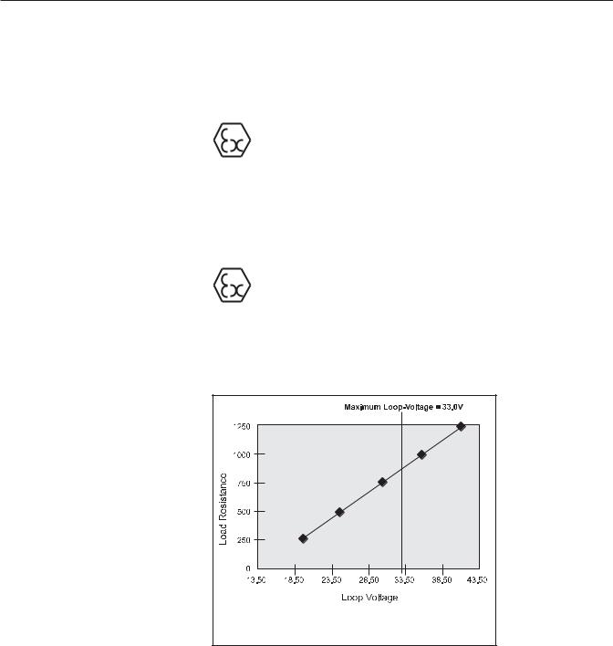
Power Supply and Maximum Load Resistance
21.0 to 33.5 Vdc Power Supply, refer to Figure 1-2 below. Input Power: Derived from Analog Output
(2-wire current loop transmitter)
Note: Load resistance should also include I.S. barrier resistance. When using Model 275 HART Communicator the minimum load resistance is 250 ohms.
Figure 1-2 Power Supply vs. Maximum Load Resistance
Output Signals
Transmitter: 4-20 mA analog output with HART
Update Rate: 4 times per sec.
Range: 3.8 to 22.0 mA
1-9

Section 1 Introduction |
Installation and Operation Manual |
Models MT 3809 & 3819
X-VA-MT3809-3819-eng Part Number: 541B049AHG September, 2008
Two Alarm Outputs (open collector)
Optically isolated outputs assignable to alarms, reverse flow indicator, or manual valve.
Maximum off-state voltage: 30 Vdc Maximum off-state current: 0.05 mA Maximum on-state voltage: 1.2 Vdc Maximum on-state current: 20 mA
One Pulse Output (open collector)
Optically isolated. Scaleable to a variety of engineering unit systems (pulses per liter, gallons, etc.)
Range: 1 Hz to 1 kHz
Maximum off-state voltage: 30 Vdc Maximum off-state current: 0.05 mA Maximum on-state voltage: 1.2 Vdc Maximum on-state current: 20 mA
Linearity
Less than 1% at maximum current
Temperature Influence
Less than 0.04% per °C
Voltage Influence
Less than 0.002%/Vdc
Load Resistance Influence
±0.1% full scale
Transmitter, Alarm and Pulse Wiring Diagrams
Refer to Figures 1-3, 1-4, 1-5 and 1-6
For Division 1 explosion proof installations, the optional explosion proof enclosure must be used. This enclosure does not use the auxiliary terminal box, as shown on some of the installation diagrams. All connections are made directly within the housing. Cable entry device shall be certified as Flame-proof type, suitable per the conditions of use and correctly installed. If used with conduit, refer to Figure 1-7, a sealing device shall be provided in accordance with Figure 1-7.
For Division 2 non-incendive installations, either the standard enclosure or the explosion proof enclosure may be used.
For both Division 1 explosion proof and Division 2 non-incendive installations, the barriers shown in the installation drawings are unnecessary. However, NEC Class 2 circuits are required.
The circuits shall be wired separately or using a Multicore Cable Type B, in accordance with EN 60079-14. Also wiring must be done in accordance with the applicable electrical codes, ie., NEC Chapter 5, CEC Section 18 and any local codes.
TRANSMITTER ACCESSORIES
General purpose and intrinsically safe HART compatible power supplies are available in 110V and 220V.
1-10
Installation and Operation Manual |
Section 1 Introduction |
X-VA-MT3809-3819-eng Part Number: 541B049AHG September, 2008
Models MT 3809 & 3819
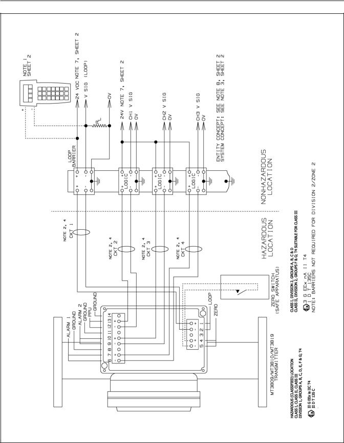
Ref. No.981Y006 - Rev. F Sheet 1 of 2
Figure 1-3 Transmitter Only Wiring Diagram
1-11

Section 1 Introduction |
Installation and Operation Manual |
Models MT 3809 & 3819
X-VA-MT3809-3819-eng Part Number: 541B049AHG September, 2008
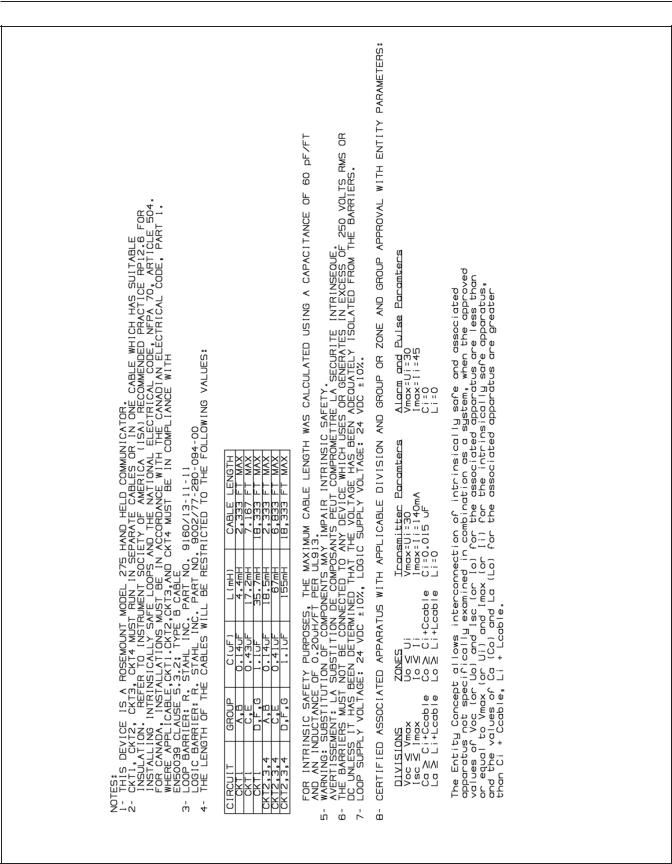
Ref. No.981Y006 - Rev. F Sheet 2 of 2
Figure 1-4 Transmitter Only Wiring Notes
1-12
Installation and Operation Manual |
Section 1 Introduction |
X-VA-MT3809-3819-eng Part Number: 541B049AHG September, 2008
Models MT 3809 & 3819
Ref. No.981Y005 - Rev. F Sheet 1 of 2
Figure 1-5 Transmitter with Alarm and Pulse Outputs Wiring Diagram
1-13
Section 1 Introduction |
Installation and Operation Manual |
Models MT 3809 & 3819
X-VA-MT3809-3819-eng Part Number: 541B049AHG September, 2008
Ref. No.981Y005 - Rev. F Sheet 2 of 2
Figure 1-6 Transmitter with Alarm and Pulse Outputs Wiring Diagram
1-14
Installation and Operation Manual |
Section 1 Introduction |
X-VA-MT3809-3819-eng Part Number: 541B049AHG September, 2008
Models MT 3809 & 3819
Ref. No.981Y008 - Rev. D Sheet 1 of 1
Figure 1-7 Model MT3809 Explosion-Proof Housing Wiring Diagram
1-15

Section 1 Introduction |
Installation and Operation Manual |
Models MT 3809 & 3819
X-VA-MT3809-3819-eng Part Number: 541B049AHG September, 2008
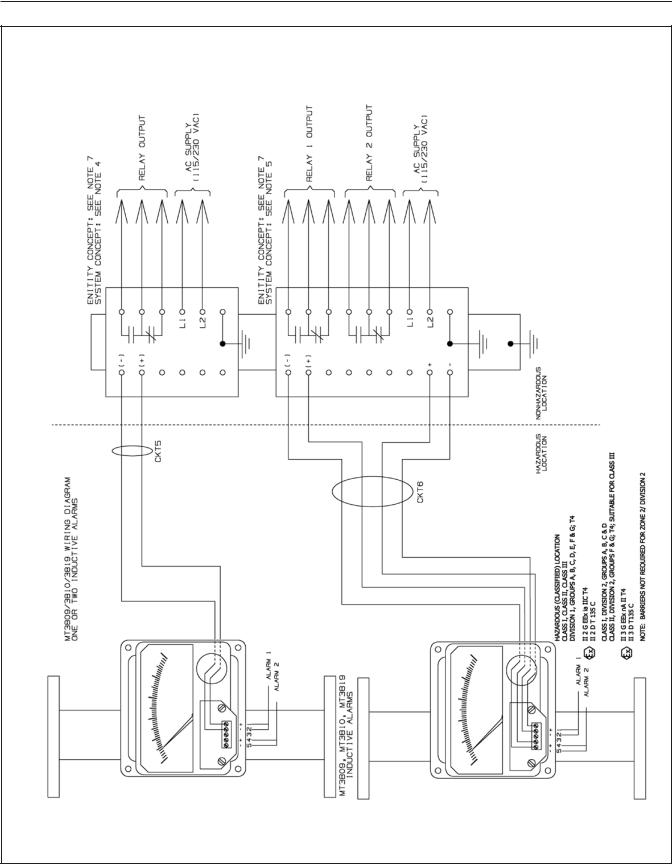
1-7 Microprocessor Transmitter with Inductive Alarms
This combined system provides both the sophistication of the microprocessor along with the simplicity of one or two switch inductive alarms. Specifications for the transmitter are as stated previously and specifications for the front adjustable inductive alarms are as follows. For Wiring Diagrams, Refer to Figures 1-8 and 1-9.
Ref. No.981Y007 - Rev. F Sheet 1 of 2
Figure 1-8 Transmitter with Inductive Alarm Wiring Diagram
1-16
 Loading...