


Installation and Operation Manual |
|
X-VA-MT3750C-eng |
|
Part Number: 541B063AAG |
Brooks® Ar-MiteTM MT3750C |
April, 2014 |
Ar-MiteTM Low Flow Armored Flowmeter
Ar-MiteTM Model MT3750 |
Ar-MiteTM Model MT3750 |
Metal Tube Flowmeter |
Metal Tube Flowmeter |
|
with Transmitter or Inductive Alarm |
|
|

|
|
|
|
|
|
|
Installation and Operation Manual |
||||
|
|
|
|
|
|
|
|
|
|
X-VA-MT3750C-eng |
|
Brooks® Ar-MiteTM MT3750C |
|
|
Par Number: 541B063AAG |
||||||||
|
|
|
|
April, 2014 |
|||||||
|
|
|
|
|
|
|
|
|
|
|
|
|
|
|
|
|
|
|
|
|
|
|
|
|
|
|
|
|
|
|
|
|
|
|
|
|
|
|
|
|
|
|
|
|
|
|
|
|
|
|
|
|
|
|
|
|
|
|
|
|
|
|
|
|
|
|
|
|
|
|
|
|
|
|
|
|
|
|
|
|
|
|
|
|
|
|
|
|
|
|
|
|
|
|
|
|
|
|
|
|
|
|
|
|
|
|
|
|
|
|
|
|
|
|
|
|
|
|
|
|
|
|
|
|
|
|
|
|
|
|
|
|
|
|
|
|
|
|
|
|
|
|
|
|
|
|
|
|
|
|
|
|
|
|
|
|
|
|
|
|
|
|
|
|
|
|
|
|
|
|
|
|
|
|
|
|
|
|
|
|
|
|
|
|
|
|
|
|
|
|
|
|
|
|
|
|
|
|
|
|
|
|
|
|
|
|
|
|
|
|
|
|
|
|
|
|
|
|
|
|
|
|
|
|
|
|
|
|
|
|
|
|
|
|
|
|
|
|
|
|
|
|
|
|
|
|
|
|
|
|
|
|
|
|
|
|
|
|
|
|
|
|
|
|
|
|
|
|
|
|
|
|
|
|
|
|
|
|
|
|
|
|
|
|
|
|
|
|
|
|
|
|
|
|
|
|
|
|
|
|
|
|
|
|
|
|
|
|
|
|
|
|
|
|
|
|
|
|
|
|
|
|
|

Installation and Operation Manual |
|
X-VA-MT3750C-eng |
|
Part Number: 541B063AAG |
Brooks® Ar-MiteTM MT3750C |
April, 2014 |
Dear Customer,
We appreciate this opportunity to service your flow measurement and control requirements with a Brooks Instrument device. Every day, flow customers all over the world turn to Brooks Instrument for solutions to their gas and liquid low-flow applications. Brooks provides an array of flow measurement and control products for various industries from biopharmaceuticals, oil and gas, fuel cell research and chemicals, to medical devices, analytical instrumentation, semiconductor manufacturing, and more.
The Brooks product you have just received is of the highest quality available, offering superior performance, reliability and value to the user. It is designed with the ever changing process conditions, accuracy requirements and hostile process environments in mind to provide you with a lifetime of dependable service.
We recommend that you read this manual in its entirety. Should you require any additional information concerning Brooks products and services, please contact your local Brooks Sales and Service Office listed on the back cover of this manual or visit www.BrooksInstrument.com
Yours sincerely,
Brooks Instrument

|
Installation and Operation Manual |
|
X-VA-MT3750C-eng |
Brooks® Ar-MiteTM MT3750C |
Par Number: 541B063AAG |
April, 2014 |
THIS PAGE WAS
INTENTIONALLY
LEFT BLANK
Installation and Operation Manual |
Contents |
|
X-VA-MT3750C-eng |
|
|
Part Number: 541B063AAG |
Brooks® Ar-MiteTM MT3750C |
|
April, 2014 |
||
Paragraph |
Page |
|
Number |
Number |
|
Introduction Section 1 |
|
|
1-1 |
Description ........................................................................................................................................ |
1-1 |
1-2 |
Specifications .................................................................................................................................... |
1-1 |
1-3 |
Optional Equipment ........................................................................................................................... |
1-4 |
Installation Section 2 |
|
|
2-1 |
General .............................................................................................................................................. |
2-1 |
2-2 |
Receipt of Equipment ........................................................................................................................ |
2-1 |
2-3 |
Recommended Storage Practice....................................................................................................... |
2-1 |
2-4 |
Return Shipment ............................................................................................................................... |
2-2 |
2-5 |
Transit Precautions ........................................................................................................................... |
2-2 |
2-6 |
Removal From Storage ..................................................................................................................... |
2-2 |
2-7 |
Installation of Flowmeter ................................................................................................................... |
2-3 |
2-8 |
Installation of Inductive Alarm ............................................................................................................ |
2-3 |
2-9 Installation of Reed Switch Alarm ...................................................................................................... |
2-4 |
|
2-10 Installation of Transmitter .................................................................................................................. |
2-5 |
|
Operation Section 3 |
|
|
3-1 |
Operating Procedure ......................................................................................................................... |
3-1 |
3-2 |
Operation of Inductive Alarm ............................................................................................................. |
3-1 |
3-3 |
Operation of Transmitter ................................................................................................................... |
3-1 |
3-4 Operation of Reed Switch Alarm ....................................................................................................... |
3-2 |
|
Maintenance Section 4 |
|
|
4-1 |
General .............................................................................................................................................. |
4-1 |
4-2 |
Service Information ........................................................................................................................... |
4-1 |
4-3 |
On Site Adjustment/Calibration ......................................................................................................... |
4-1 |
Parts List Section 5 |
|
|
5-1 |
General .............................................................................................................................................. |
5-1 |
Essential Instructions Section A |
|
|
Essential Instructions ................................................................................................................................ |
A-1 |
|
Warranty, Local Sales/Service Contact Information....................................................................... |
Back Cover |
|
i
|
Contents |
Installation and Operation Manual |
||
|
|
|
X-VA-MT3750C-eng |
|
Brooks® Ar-MiteTM MT3750C |
Part Number: 541B063AAG |
|||
|
April, 2014 |
|||
|
|
|
|
|
Figures |
|
|
|
|
|
Figure |
|
Page |
|
|
Number |
|
Number |
|
|
1-1 Model MT3750C with Transmitter / Inductive Alarm .......................................................................... |
|
1-5 |
|
|
1-2 Reed Switch Wiring Diagram ............................................................................................................ |
|
1-6 |
|
|
1-3 Model MT3750C with Reed Switch Alarm ......................................................................................... |
|
1-7 |
|
|
1-4 Power Supply vs. Maximum Load Resistance ................................................................................. |
|
1-10 |
|
1-5 |
Transmitter Wiring Diagram ............................................................................................................. |
|
1-10 |
|
|
1-6 Dimensions for MT3750C Flanged and Threaded Metal Tube Flowmeter with Indicator ................. |
1-11 |
||
|
1-7 Dimensions for MT3750C Flanged and Threaded |
|
|
|
|
|
Connections with Transmitter or Inductive Alarm ............................................................................. |
|
1-12 |
|
1-8 Dimensions for MT3750C Flanged and Threaded Connections with Reed Switch Alarm ................ |
1-13 |
||
|
1-9 Dimensions for MT3750C Panel Mounting ....................................................................................... |
|
1-14 |
|
2-1 |
Typical Installation ............................................................................................................................. |
|
2-3 |
|
|
2-2 Inductive Switch Wiring Diagram ....................................................................................................... |
|
2-4 |
|
2-3 |
Inductive Switch Wiring ..................................................................................................................... |
|
2-6 |
|
|
2-4 Reed Switch Alarm Wiring Using IS Barrier ...................................................................................... |
|
2-7 |
|
|
2-5 Reed Switch Alarm Installation using P & F Relay Unit ..................................................................... |
|
2-8 |
|
|
2-6 Reed Switch Alarm Wiring Using P & F Relay Unit ........................................................................... |
|
2-8 |
|
|
2-7 Transmitter Wiring Diagram for I.S. Systems .................................................................................... |
|
2-9 |
|
|
2-8 Transmitter Wiring Diagram for XP Systems.................................................................................... |
|
2-10 |
|
2-9 |
Transmitter Wiring Diagram ............................................................................................................. |
|
2-11 |
|
3-1 |
Reed Switch Alarm ............................................................................................................................ |
|
3-4 |
|
|
5-1 Model MT3750 Exploded View .......................................................................................................... |
|
5-2 |
|
Tables |
|
|
|
|
|
Table |
|
Page |
|
|
Number |
|
Number |
|
1-1 |
Capacities.......................................................................................................................................... |
|
1-3 |
|
|
1-2 Pressure Ratings in PSIG (Bar G) ..................................................................................................... |
|
1-3 |
|
|
1-3 Fluid Temperature at Ambient Temperature ...................................................................................... |
|
1-3 |
|
|
3-1 Interior Label MT3750 Ar-Mite Alarm ................................................................................................. |
|
3-3 |
|
|
5-1 Model MT3750 Recommended Spare Parts List (Refer to Figure 5-1) ............................................. |
|
5-3 |
|
|
5-2 Model MT3750 Indicator, Alarm and Transmitter Spare Parts List .................................................... |
|
5-4 |
|
ii

Installation and Operation Manual |
|
|
|
|
Section 1 Introduction |
||||
X-VA-MT3750C-eng |
|
|
|
|
|
|
|
|
|
Part Number: 541B063AAG |
|
|
Brooks® Ar-MiteTM MT3750C |
||||||
April, 2014 |
|
|
|||||||
1-1 Description |
|
|
|
|
|
|
|
|
|
|
|
|
|
|
|
|
|||
|
|
|
|
|
|
|
|
||
|
The Brooks® Ar-MiteTM is a reliable, low flow metal tube flowmeter with |
||||||||
|
316L stainless steel wetted parts. The magnetically coupled indicator |
||||||||
|
provides a highly reliable method of indication. This model is a practical |
||||||||
|
and economical approach to low flow rate indication for high pressure and |
||||||||
|
difficult to handle fluids. Optional accessories include 4-20 mA output, |
||||||||
|
Needle Valve, Flow Controllers and Alarms. |
||||||||
1-2 Specifications |
|
|
|
|
|
|
|
|
|
|
|
|
|
|
|
|
|
|
|
|
|
|
|
|
|
|
|
|
|
|
|
|
|
|
|
|
|
|
|
|
|
|
|
|
|
|
|
|
|
|
|
|
|
|
|
|
|
|
|
|
|
|
|
|
|
|
|
|
|
|
|
|
|
|
|
|
|
|
|
|
|
|
|
|
|
|
|
|
|
|
|
|
|
|
|
|
|
|
|
|
|
|
|
|
|
|
|
|
|
Performance Specifications Flow
Liquids up to 100 l/h or 26 GPH (Water equiv.) Gases up to 3.1 m3n/h or 120 SCFH (Air equiv.) (See Table 1-1 for more information)
Accuracy
±5% Full Scale, Class 4 to VDE/VDI 3513, Optional ±3% Full Scale, Class 2.5 to VDE/VDI 3513
Repeatability
1% full scale
Pressure Ratings Maximum fluid pressure:
All non-flanged meters: 1500 psig (100 bar) Flange connections: (Refer to Table 1-2) Optional maximum operating pressure: 4000 psig (276 bar) (no valve, 1/4" NPT option only)
Scales
Length - 52 mm, nominal
Types - Detachable aluminum direct reading scales in engineering and reference units
Operating Fluid Temperature Limits
Indicator: -20°F(-29°C) to 400°F (204°C)
Alarm: -20°F(-29°C) 250°F (120°C)
Transmitter: -20°F(-29°C) 180°F (82°C)
Ambient Temperature:
Indicator: -58°F(-50°C) to 150°F(65°C) Alarm: -20°F(-29°C) to 150°F(65°C) Transmitter: -20°F(-29°C) to 150°F(65°C) (Refer to Table 1-3)
1-1

Section 1 Introduction |
Installation and Operation Manual |
|
|
|
X-VA-MT3750C-eng |
Brooks® Ar-MiteTM MT3750C |
Part Number: 541B063AAG |
|
April, 2014 |
||
Materials of Construction: |
|
|
|
|
|
|
|
|
|
|
|
Process Wetted
316L stainless steel (1.4404), Inconel® 625, Titanium Grade II (Size 0 float only) Optional Monel® K-500 (sizes 1-6 only)
O-rings
Standard: Viton® Fluoroelastomers;
Option: Buna-N, Ethylene Proplylene, Kalrez®,
PTFE Teflon® (without valve)
Enclosure Ratings
All Housings Epoxy painted die cast aluminum
Indicator Housing: Type 4X/ IP64
Transmitter Enclosure: Type 4X/ IP66/ IP67
Reed Switch Eclosure: Type 4X
Inductive Alarm Enclosure: Type 4X/ IP65
Connections
Fittings Horizontal
1/4" NPT Female Threaded 1/4" Tube Compression
6 mm Tube Compression 1/4" ISO RC
(Refer to Figures 1-6 thru 1-9)
Flanges
EN1092 DN15 to DN25 PN40 RF
ANSI B16.5 1/2", 3/4" or 1" - 150#, 300#, 600# RF Vertical Inlet and Outlet Only
(Refer to Figures 1-6 thru 1-9)
Pressure Equipment Directive (PED) 97/23/EC
Flowmeters metnioned in this instruction manual are Sound Engineering
Practice (SEP).
•Pressurized materials are manufactured in compliance with material standard ASTM.
•Applied welding method is in accordance with ASME IX / EN 287-288.
•Flowmeters are designed in accordance with ASME B31.3 and ASME B31.1
•Admissable maximum temperatures and pressure are stated further in this manual.
1-2

Installation and Operation Manual |
|
|
|
Section 1 Introduction |
||||||
X-VA-MT3750C-eng |
|
|
|
|
|
|
|
|
|
|
Part Number: 541B063AAG |
|
|
Brooks® Ar-MiteTM MT3750C |
|||||||
April, 2014 |
|
|
|
|||||||
Table 1-1 Capacities |
|
|
|
|
|
|
|
|
|
|
Meter |
|
|
|
|
|
Viscosity Limit |
Pressure Drop |
|
|
|
Size |
|
Flow Range |
|
|
|
|
|
|
|
|
|
|
|
|
|
|
|
|
|
|
|
|
|
|
|
|
|
|
|
|
|
|
|
Water |
|
|
Air(1,2) |
|
|
|
|
|
|
|
GPH |
l/h |
In/h |
SCFH |
m3n/h |
CP |
mBar |
Inches WC |
|
|
0 |
0.021-0.21 |
0.08-0.8 |
3.9-39 |
0.15-1.5 |
- |
5 |
12 |
4.8 |
|
|
1 |
0.034-0.34 |
0.13-1.3 |
5.6-56 |
0.21-2.1 |
- |
10 |
12 |
4.8 |
|
|
2 |
0.095-0.95 |
0.36-3.6 |
13.0-120 |
0.5-4.9 |
- |
20 |
12 |
4.8 |
|
|
3 |
0.29-2.8 |
1.0-10 |
- |
1.2-12 |
0.033-0.33 |
35 |
12 |
4.8 |
|
|
4 |
0.55-5.5 |
2.1-21 |
- |
2.5-23 |
0.063-0.62 |
70 |
32 |
12.8 |
|
|
5 |
1.1-11 |
4.2-42 |
- |
5.4-53 |
0.15-1.3 |
100 |
38 |
15.3 |
|
|
6 |
2.8-26 |
11-100 |
- |
12-110 |
0.31-3.1 |
130 |
44 |
17.7 |
|
|
|
|
|
|
|
|
|
|
|
|
|
Notes:
1.Air flows in scfm converted to 70oF and 14.7 psia when the meter is operated at 70oF and 14.7 psia.
2.Air flows in m3n/h (converted to normal conditions: 0oC and 1.013 bar abs) when the meter is operated at 1.013 bar abs and 20oC.
Table 1-2 Pressure Ratings in PSIG (Bar G)
|
-20°F TO 100°F |
|
|
|
FLANGE RATING |
-29°C TO 39°C |
200°F 93°C |
300°F 149°C |
400°F 204°C |
150# |
275 (19) |
240 (16) |
215 (15) |
195 (13) |
300# |
720 (49.5) |
620 (43) |
560 (39) |
515 (35) |
600# |
1440 (99) |
1240 (85) |
1120 (77) |
1030 (71) |
Table 1-3 Fluid Temperature at Ambient Temperature
MAX. AMBIENT
TEMPERATURE
° F |
° C |
104 |
40 |
110 |
43 |
120 |
49 |
130 |
54 |
140 |
60 |
150 |
65 |
Notes:
|
MAX. FLUID TEMPERATURE PER OPTION |
|
||||
INDICATOR |
ALARM |
|
TRANSMITTER |
|||
° F |
° C |
° F |
|
° C |
° F |
° C |
400 |
204 |
250 |
|
120 |
180 |
82 |
390 |
199 |
250 |
|
120 |
175 |
79 |
380 |
193 |
250 |
|
120 |
170 |
76 |
370 |
187 |
250 |
|
120 |
165 |
74 |
360 |
182 |
240 |
|
115 |
155 |
68 |
350 |
176 |
235 |
|
112 |
150 |
65 |
1.At ambient temperatures less than 104°F (40°C), the maximum fluid temperature does not increase.
2.Ambient temperature is limited to 150°F (65°C) maximum.
1-3

Section 1 Introduction |
Installation and Operation Manual |
|
X-VA-MT3750C-eng |
Brooks® Ar-MiteTM MT3750C |
Part Number: 541B063AAG |
April, 2014 |
|
1-3 Optional Equipment |
|
|
|
Standard Needle Valves
The standard needle or cartridge valves can be supplied integrally mounted to the inlet fitting of the instrument. The optional NRSTM needle valve, also integrally mounted to the inlet fitting, provides a greater number of turns affording precision control. For more details on the needle or cartridge valves go to our website: BrooksInstrument.com,
select Documentation,Precision Valves and Flow Controllers, Brooks-Line IVTM, CART valves or NRS valves.
Limit Switches Inductive Alarm Switch
One or two electronic limit switches type SJ2-N can be installed in the indicator housing to allow initiation of signaling or switching functions on a preset flow value being reached. The SJ2-N limit switch operates as a slot initiator that is inductively actuated by a cam mounted to the pointer. Any flow value can be used for setting the limit value by sliding the switch along the slot in the mounting plate for the initiators. Minimum setting distance between two limit switches is approximately 50% of the scale range. (Refer to Figure 1-1)
Power supply |
8 Vdc (Max. 15.5 Vdc) |
Current consumption |
active area clear: > 3 mA |
Current consumption |
active area obscured: < 1 mA |
Self inductance |
29 μH |
Self capacitance |
20 nF |
Max Temp: |
158°F(70°C) |
Inductive Alarm |
|
Electrical Classification |
|
Intrinsically Safe: |
|
|
ATEX: KEMA 02ATEX1126 |
|
|
II 2 G Ex ia IIC T6 |
|
|
per EN 60079-0: 2006 EN 60079-11: 2007 |
|
|
EN 61241-0: 2006 EN 61241-11: 2006 |
|
|
II 2 D Ex iaD 21 IP65 T 75OC |
|
|
IECEx KEM 09.0046 |
|
|
Ex ia IIC T6 Gb/Ex ia IIIC T 75OC Db IP65 |
|
|
per IEC 60079-0: 2007-10 IEC 60079-11: 2006 |
|
|
IEC 61241-11: 2005 |
|
|
CSA: (USA and Canada) 1379260 |
|
|
Class I, II, III, Div. 1, Groups A thru G, T6 |
|
|
per CSA -157:1992 ; UL913:2002 |
|
|
Class I, Zone 0, Zone 1 AEx ia IIC, T6 |
|
|
per ANSI/ UL 2279: 1996 |
|
1-4 |
Ex ia IIC |
|
per CSA E79-0:2002; CSA E79-11:2002 |
||
|
Installation and Operation Manual |
Section 1 Introduction |
|
X-VA-MT3750C-eng |
|
|
Part Number: 541B063AAG |
Brooks® Ar-MiteTM MT3750C |
|
April, 2014 |
||
|
|
|
|
|
|
Figure 1-1 Model MT3750C with Transmitter / Inductive Alarm
NEPSI: (China) GYJ11.1639
Ex ia IIC T6 Gb
per GB3836.1-2010; GB3836.4:2010 |
|
GOST-R 0813793 |
|
Approval POCC NL. 06.B01220 |
|
Non Incendive: |
|
ATEX: KEMA 02ATEX1127 |
|
II 3 GD T 75oC |
|
EEx nA II T6 |
|
per EN60079-15: 2003; |
|
EN50281-1-1-1: 1998 +A1 |
|
CSA: (USA and Canada) 1379260 |
|
NI, Class I, II, III, Div. 2, Groups A thru G, T6 |
|
per CSA -213:1987 ; UL1604:1995 |
|
Class I, Zone 2 AEx nA II, T6 |
|
per ANSI/ UL 2279: 1996 |
|
Ex nA II |
|
per CSA E79-0:2002; CSA E79-15:2002 |
|
NEPSI: (China) GYJ13.1315 |
|
Ex nA IIC T6 Gc |
|
per GB3836.1:2010; GB3836.8:2003 |
|
GOST-R 0813793 |
|
Approval POCC NL. 06.B01220 |
1-5 |
Section 1 Introduction |
Installation and Operation Manual |
|
X-VA-MT3750C-eng |
Brooks® Ar-MiteTM MT3750C |
Part Number: 541B063AAG |
April, 2014 |
|
|
|
|
|
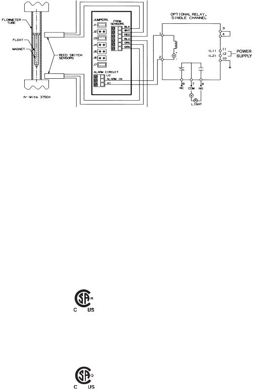
Figure 1-2 Reed Switch Wiring Diagram
Reed Switch Alarm
Two reed switches are installed in the alarm housing to provide signaling or switching functions when a preset flow value has been reached. The reed switches provide high, low or dual setpoints and latched output over the full range. The switches are normally adjusted to the desired flow range in the factory. Modifications to the switch settings can be made in the field, refer to Section 3-4. Minimum setting distance between two switches is approximately 40% of the scale. (Refer to Figures 1-2 and 1-3)
Data Reed Switch |
|
Maximum Voltage* |
175 Vdc, 124 Vac |
Maximum Current* |
250 mA |
Maximum Contact Rating* |
3 Watts |
(Maximum Switch Specifications) |
|
Electrical Classification |
|
Non Incendive: |
|
Maximum Voltage |
30 Vdc |
Maximum Current |
100 mA |
Maximum Contact Rating |
3 Watts |
CSA (US and Canada) |
|
NI Class I, Div. 2, Groups A, B, C and D: Class II Groups F and G, T6
per CSA-213: 1987; UL 1604; 1995
Intrinsic Safety:
Entity parameters
Vmax = Ui = 30 Vdc, Imax = Ii = 100 mA, Ci = 0, Li = 0
CSA: (US and Canada)
IS Class I, II, III, Div. 1, Groups A thru G, T6 per CSA-157:1992; UL 913:2002
1-6

Installation and Operation Manual |
|
|
Section 1 Introduction |
|
X-VA-MT3750C-eng |
|
|
|
|
Part Number: 541B063AAG |
|
|
Brooks® Ar-MiteTM MT3750C |
|
April, 2014 |
|
|
||
|
|
|
|
|
|
|
|
|
|
|
|
|
|
|
|
|
|
|
|
Figure 1-3 Model MT3750C with Reed Switch Alarm
Transmitter: 3750
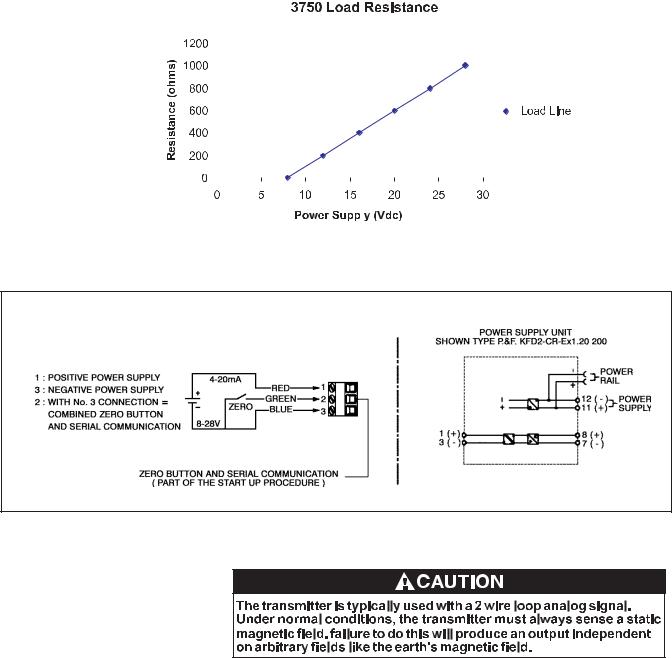
The transmitter provides accurate magnet angle detection and conversion to a 4 - 20 mA industry standard output signal, based on the position of a float assembly in the flowmeter. This rugged, compact, microprocessordriven device is capable of providing accurate flow information to your external support systems. The patented magnetic sensor with automatic gain control enables an extremely high dynamic capture range without sacrificing accuracy. (Refer to Figures 1-1, 1-4 and 1-5)
Data Certifications:
E.M.C. Directive 2004/108/EC according to EN 61326-1: 2006 Flame-proof/ Explosion-proof:
Power Supply 28 Vdc, 4-20 mA
Ambient Temperature: -25oC < Tamb < 65oC Flameproof/ Explosion-proof
ATEX: KEMA 01ATEX2174 II 2 G Ex d IIC T6
II 2 D Ex tD A 21 IP66 T 85oC
per EN 60079-0: 2006; EN 60079-1: 2004; EN61241-0: 2006;
EN61241: 2004
UL: United States and Canada Ul Listed, E73889
XP Class I, Div.1, Groups A, B, C, and D, T6 

 DIP Class II, Div. 1, Groups E, F, and G
  per UL 1203: 2000; CSA-30: 1986
Class I, Zone 1 AEx d IIC T6 per UL 2279: 1996
Ex d IIC T6
per CSA E79-0:2002; CSA E79-1:2002
NEPSI: (China) GYJ11.1638X
Ex d IIC T6 Gb
per GB3836.1-2010; GB3836.2-2010 |
|
IECEx: KEM 06.0049 |
|
EX d IIC T6 |
|
per IEC 60079-0: 2004; IEC 60079-1: 2003 |
|
GOST-R 0813793 |
|
Approval POCC NL. 06.B01220 |
1-7 |

Section 1 Introduction |
Installation and Operation Manual |
|
X-VA-MT3750C-eng |
Brooks® Ar-MiteTM MT3750C |
Part Number: 541B063AAG |
April, 2014 |
Intrinsic Safety: Functional parameters
Power Supply 8-28 Vdc, Imax= 22 mA Entity Parameters:
Ui = 30 V DC, Ii = 100 mA Pi = 750 mW Ci = 0uF Li = 1.8 mH
Ambient Temperature: -30oC < Tamb < 65oC ATEX: KEMA 01ATEX1033
II 2 G Ex ia IIC T6
II 2 D Ex iaD 21 IP66/IP67 T70°C II 2 D Ex tD A21 IP66/IP67 T70°C
per EN 60079-0: 2006 EN 60079-11: 2007 EN 61241-0: 2006 EN 61241-11: 2006
CSA: (US and Canada)
IS Class I, II, III, Div.1, Groups A, thru G, T6 per UL913:2002; CSA -157:1992
Class I, Zone 1 AEx ia IIC T6 per UL 2279:1996
Ex ia IIC T6
per CSA E79-0:2002; CSA E79-11: 2002
NEPSI: (China) GYJ11.1637
Ex ia IIC T6 Gb Ex iaD 21 T 70°C
per GB 3836.1/4-2010, IEC 61241-0:2004, GB 12476.4-2010
IECEx: KEM 06.0037 EX ia IIC T6
per IEC 60079-0: 2004; IEC 60079-11:1999
GOST-R 0813793
Approval POCC NL. 06.B01220
1-8

Installation and Operation Manual |
Section 1 Introduction |
|
X-VA-MT3750C-eng |
|
|
Part Number: 541B063AAG |
Brooks® Ar-MiteTM MT3750C |
|
April, 2014 |
||
|
|
|
Non Incendive
Power Supply 8-28 Vdc, Imax= 22 mA Ambient Temperature: -30oC < Tamb < 65oC ATEX: KEMA 01ATEX1035
II 3 GD T 70°C
EEx nA II T6 IP66/67
per EN 60079-15: 2003; EN 50281-1: 1998
CSA: (US and Canada)
NI Class I, Div.2, Grps A, B, C, and D; Class II Grps F and G, T6
per UL 1604: 1995; CSA-213: 1987 Class I, Zone 1 AEx nA II T6
per UL 2279: 1996 Ex nA II T6
per CSA E79-0:2002; CSA E79-15:2002
IECEx: KEM 06.0037
Ex nA II T6
per IEC 60079-0: 2004; IEC 60079-15: 2005
GOST-R 0813793
Approval POCC NL. 06.B01220
1-9
Section 1 Introduction |
Installation and Operation Manual |
||||||||||
|
|
|
|
|
|
|
|
|
X-VA-MT3750C-eng |
||
Brooks® Ar-MiteTM MT3750C |
|
|
|
Part Number: 541B063AAG |
|||||||
|
|
|
|
|
|
April, 2014 |
|||||
|
|
|
|
|
|
|
|
|
|
|
|
|
|
|
|
|
|
|
|
|
|
|
|
|
|
|
|
|
|
|
|
|
|
|
|
|
|
|
|
|
|
|
|
|
|
|
|
|
|
|
|
|
|
|
|
|
|
|
|
|
|
|
|
|
|
|
|
|
|
|
|
|
|
|
|
|
|
|
|
|
|
|
|
|
|
|
|
|
|
|
|
|
|
|
|
|
|
|
|
|
|
|
|
|
|
|
|
|
|
|
|
|
|
|
|
|
|
|
|
|
|
|
|
|
|
|
|
|
|
|
|
|
|
|
|
|
|
|
|
|
|
|
|
|
|
|
|
|
|
|
|
|
|
|
|
|
|
|
|
|
|
|
|
|
|
|
|
|
|
|
|
|
|
|
|
|
|
|
|
|
|
|
|
|
|
|
|
|
|
|
|
Figure 1-4 Power Supply vs. Maximum Load Resistance
Figure 1-5 Transmitter Wiring Diagram
Flow Controllers
Flow controllers can be supplied integrally mounted to the inlet or outlet of the instrument. For the flow controller's complete instruction manual go to our website: BrooksInstrument.com, select documentation, Precision Valves and Flow Controllers, FC8800, or FC8900.
Material certification for pressure containing
Tube and fittings according to EN10204 Level 3.1
Valve parts and plugs are according to EN10204 Level 2.2
1-10

Installation and Operation Manual |
Section 1 Introduction |
|
X-VA-MT3750C-eng |
|
|
Part Number: 541B063AAG |
Brooks® Ar-MiteTM MT3750C |
|
April, 2014 |
||
|
|
|
MM
[ INCH ]
Figure 1-6 Dimensions for MT3750C Flanged and Threaded Metal Tube Flowmeter with Indicator |
1-11 |

Section 1 Introduction |
Installation and Operation Manual |
|
X-VA-MT3750C-eng |
Brooks® Ar-MiteTM MT3750C |
Part Number: 541B063AAG |
April, 2014 |
MM |
[ INCH ] |
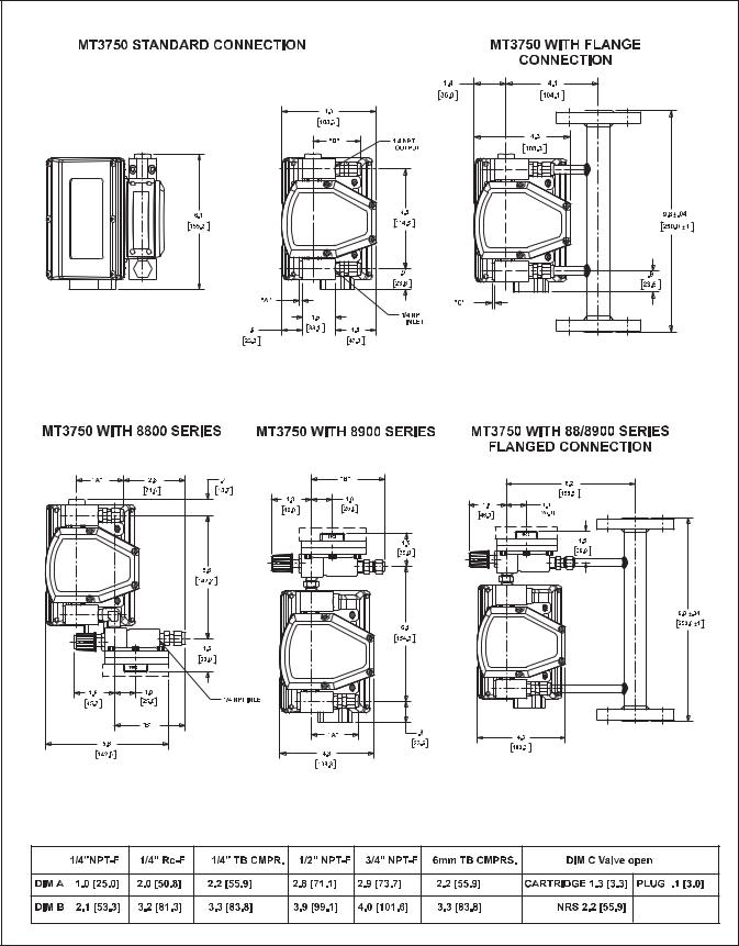
1-12 Figure 1-7 Dimensions for MT3750C Flanged and Threaded Connections with Transmitter or Inductive Alarm
Installation and Operation Manual |
Section 1 Introduction |
|
X-VA-MT3750C-eng |
|
|
Part Number: 541B063AAG |
Brooks® Ar-MiteTM MT3750C |
|
April, 2014 |
||
|
|
|
INCH |
[ MM ] |
Figure 1-8 Dimensions for MT3750C Flanged and Threaded Connections with Reed Switch Alarm |
1-13 |
Section 1 Introduction |
|
|
Installation and Operation Manual |
|
|
|
|
|
X-VA-MT3750C-eng |
Brooks® Ar-MiteTM MT3750C |
|
|
Part Number: 541B063AAG |
|
|
|
April, 2014 |
||
|
|
|
|
|
|
|
|
|
|
|
|
|
|
|
|
|
|
|
|
|
|
|
|
|
|
|
|
|
|
|
|
|
|
|
|
|
|
|
|
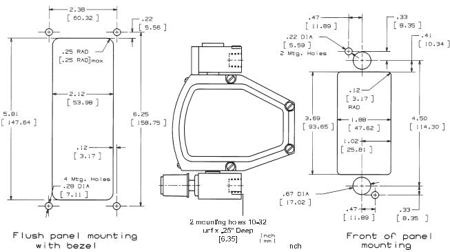
Figure 1-9 Dimensions for MT 3750C Panel Mounting
1-14
 Loading...