

Page 1

DS-TMF-GF135-MFC-eng
November, 2017
Data Sheet
GF135
Digital Mass Flow Controller
Model GF135
Thermal Mass Flow
Pressure Transient Insensitive
Mass Flow Controller with Real-Time
Flow Error Detection and Advanced Diagnostics
OverviewOverview
Overview
OverviewOverview
Designed for the next step in semiconductor etch, thin film and other advanced process
gas control applications, the GF135 combines all of the benefits provided by the most
advanced pressure transient insensitive mass flow controller (MFC) and adds real-time
flow error detection with advanced diagnostics.
Device manufacturers are driving programs to improve wafer level yield. The current
downstream quality control approach can allow hundreds of wafers to be processed
before issues are detected. Process gas stability and repeatability have been identified as
critical to meeting yield enhancement goals and MFC accuracy has been identified as
critical to maintaining process control.
The GF135 provides third generation pressure transient insensitivity, market leading
process gas accuracy and ultra fast flow settling times for reduced process cycle time and
to address advanced 3D device processing requirements. This platform also offers patent
pending real-time flow error trending using Rate of Decay (ROD) techniques that are
immune to typical MFC failure/degradation modes ensuring accurate and reliable
diagnostic capabilities. After a baseline is established at tool start-up, the GF135 can
detect changes in flow rate to within 2% of set point. These advanced diagnostic
capabilities provide a shift from downstream quality control to real-time quality
assurance and predictive maintenance resulting in higher yield and improved uptime.
PrPr
oduct Descriptionoduct Description
Pr
oduct Description
PrPr
oduct Descriptionoduct Description
The GF135, with integral real-time ROD flow error detection, drops into the standard
ultra high purity surface mount or VCR® MFC footprint providing an easy path to upgrade
critical gas lines on existing systems.
With the GF135, the user will be able to take advantage of enhanced process gas
accuracy, market leading pressure transient performance and MFC health indicators such
as automatic trending of sensor stability and valve shutdown (leak-by). Using these
health indicators and user programmable alarm limits, via MFC service port or remote
digital commands, the user can establish limits to improve the yield and/or manage
maintenance schedules to maximize uptime.
1
Page 2
FeaturFeatur
Featur
FeaturFeatur
FeaturFeatur
Featur
FeaturFeatur
Real-time flow error detection Support yield improvement programs by capturing wafer impacting flow deviations
Sensor stability tracking Improves system uptime by supporting predictive maintenance
Valve leak-by tracking Allows user to monitor and set limits to minimze first wafer effects
Enhanced process gas accuracy Meet process gas chemistry control challenges at 10nm
Market leading ultra-fast flow settling time Optimize wafer process cycle time by reducing non-productive flow stabilizaton steps.
Enhanced pressure insensitivity Superior process gas control for enhanced etch and deposition control
Corrosion resistant Hastelloy
Drop-in upgrade for surface-mount and VCR MFCs Easy upgrade for critical gas lines on existing systems
PrPr
Pr
PrPr
Real-time Flow Error DetectionReal-time Flow Error Detection
Real-time Flow Error Detection
Real-time Flow Error DetectionReal-time Flow Error Detection
es and Benefitses and Benefits
es and Benefits
es and Benefitses and Benefits
eses
es
eses
®
sensor Provides unmatched long-term sensor stability ensuring maximum yield and throughput
oduct Descriptionoduct Description
oduct Description
oduct Descriptionoduct Description
BenefitsBenefits
Benefits
BenefitsBenefits
Supports advanced 3D device processing
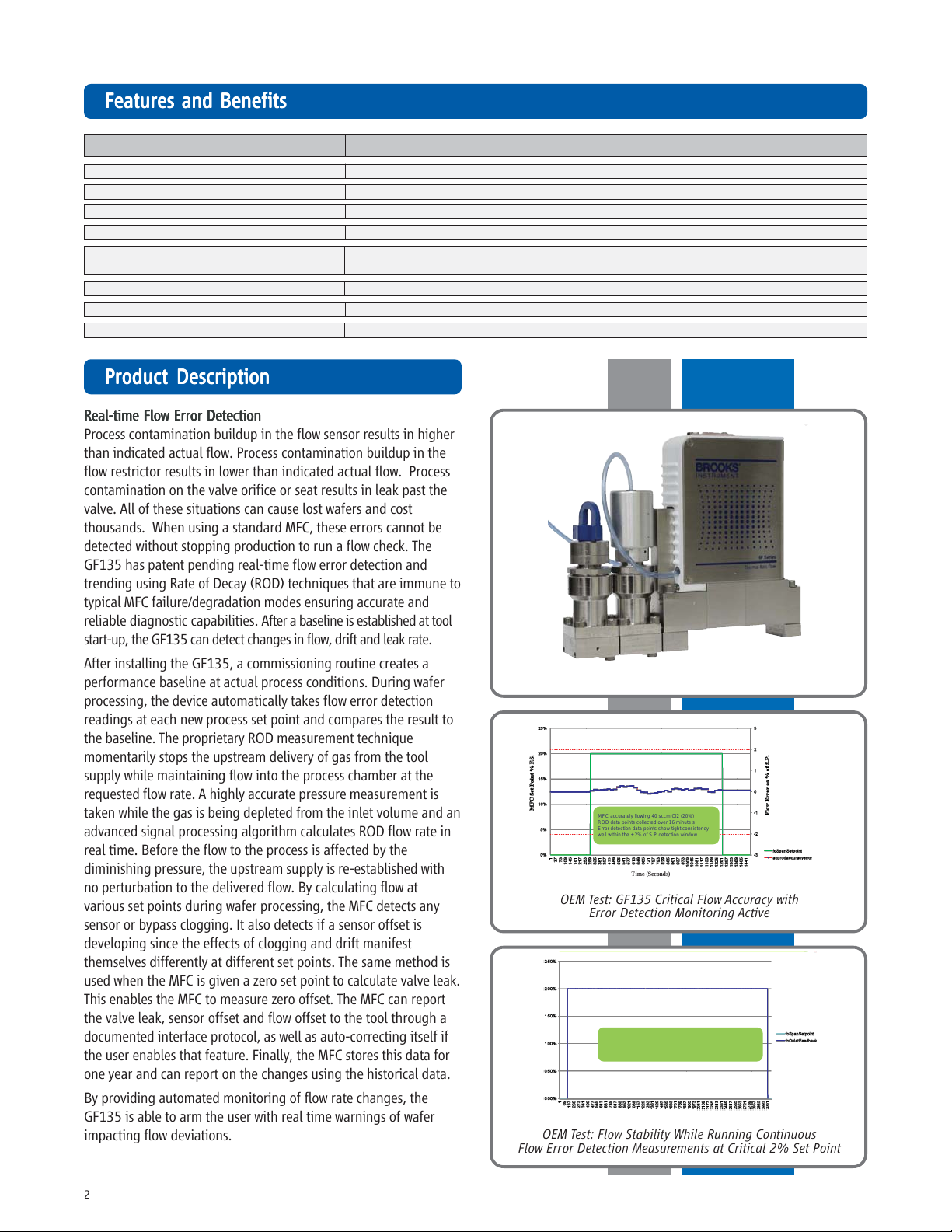
Process contamination buildup in the flow sensor results in higher
than indicated actual flow. Process contamination buildup in the
flow restrictor results in lower than indicated actual flow. Process
contamination on the valve orifice or seat results in leak past the
valve. All of these situations can cause lost wafers and cost
thousands. When using a standard MFC, these errors cannot be
detected without stopping production to run a flow check. The
GF135 has patent pending real-time flow error detection and
trending using Rate of Decay (ROD) techniques that are immune to
typical MFC failure/degradation modes ensuring accurate and
reliable diagnostic capabilities. After a baseline is established at tool
start-up, the GF135 can detect changes in flow, drift and leak rate.
After installing the GF135, a commissioning routine creates a
performance baseline at actual process conditions. During wafer
Model GF135 on Gas Stick
processing, the device automatically takes flow error detection
readings at each new process set point and compares the result to
the baseline. The proprietary ROD measurement technique
momentarily stops the upstream delivery of gas from the tool
supply while maintaining flow into the process chamber at the
requested flow rate. A highly accurate pressure measurement is
taken while the gas is being depleted from the inlet volume and an
advanced signal processing algorithm calculates ROD flow rate in
MFC accurately flowing 40 sccm Cl2 (20%)
ROD data points collected over 16 minute s
Error detection data points show tight consistency
well within the ± 2% of S.P detection window
real time. Before the flow to the process is affected by the
diminishing pressure, the upstream supply is re-established with
no perturbation to the delivered flow. By calculating flow at
various set points during wafer processing, the MFC detects any
sensor or bypass clogging. It also detects if a sensor offset is
OEM Test: GF135 Critical Flow Accuracy with
Time (Seconds)
Error Detection Monitoring Active
developing since the effects of clogging and drift manifest
themselves differently at different set points. The same method is
used when the MFC is given a zero set point to calculate valve leak.
This enables the MFC to measure zero offset. The MFC can report
the valve leak, sensor offset and flow offset to the tool through a
documented interface protocol, as well as auto-correcting itself if
the user enables that feature. Finally, the MFC stores this data for
MFC flowing 4 sccm Cl2 (2% of F.S.) for 50 minutes
ROD measurements taken at 5 second intervals
No spiking or overshoot after each ROD measurement
one year and can report on the changes using the historical data.
By providing automated monitoring of flow rate changes, the
GF135 is able to arm the user with real time warnings of wafer
impacting flow deviations.
OEM Test: Flow Stability While Running Continuous
Flow Error Detection Measurements at Critical 2% Set Point
2
Page 3
PrPr
oduct Description (conoduct Description (con
Pr
oduct Description (con
PrPr
oduct Description (conoduct Description (con
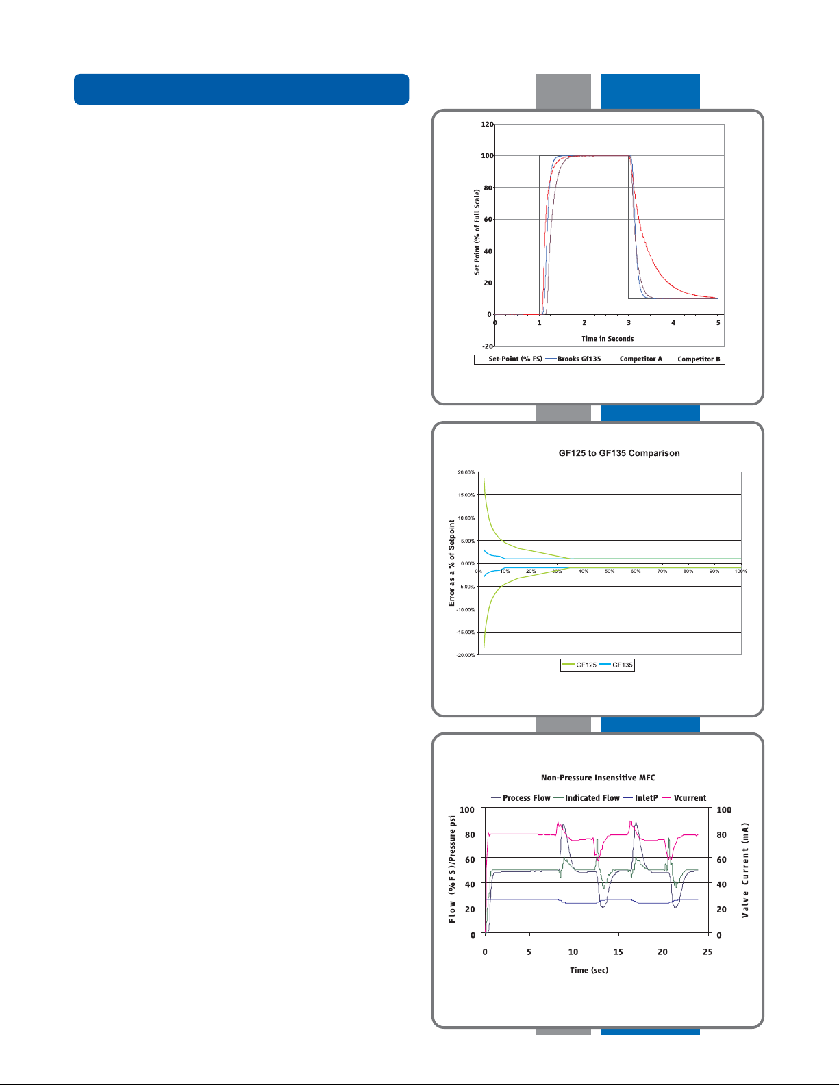
Ultra-Fast ResponseUltra-Fast Response
Ultra-Fast Response
Ultra-Fast ResponseUltra-Fast Response
By combining Brooks’ patented flow sensor technology with a
high speed ARM processor and fast acting diaphragm free valve
assembly, the GF Series delivers up to 3 times faster response
and settling time compared to other mass flow controllers,
enabling:
• Improved wafer throughput by reducing nonproductive flow
settling steps
• Critical Etch and 3D device processes requiring ultra-fast sub
500 millisecond etch steps
• Reduced diverted gas consumption and associated
abatement costs
• Time-sensitive gas delivery steps in Atomic Layer Deposition (ALD)
• Processes requiring a slow ramped gas turn-on or time
critical transitions between flow rates with user
programmable ramp function
Enhanced Process Gas AccuracyEnhanced Process Gas Accuracy
Enhanced Process Gas Accuracy
Enhanced Process Gas AccuracyEnhanced Process Gas Accuracy
A major advancement over traditional single point gas
conversion factors, Brooks delivers up to a three-times
improvement in process gas accuracy. This is achieved through
advanced gas modeling optimized through actual gas testing
providing compensation for non-linear gases.
tinued)tinued)
tinued)
tinued)tinued)
Comparison of GF135 vs Competititor’s Response Time
to Ascending & Descending Set Points
The GF135 is a gas and range specific device for critical gas
process applications requiring the widest working range with
tightest flow control accuracy. A typical application is for multistep processes requiring a high flow rate (up to 5 slpm) and a
very accurate low flow rate. Traditionally this has been
addressed by using two mass flow controllers. With wide
turndown (100:1) and superior accuracy offered by the GF135,
it is often possible to replace two mass flow controllers with
one, providing immediate cost savings while freeing up a gas
line for greater gas panel flexibility.
Pressure Transient InsensitivityPressure Transient Insensitivity
Pressure Transient Insensitivity
Pressure Transient InsensitivityPressure Transient Insensitivity
Cost and space constraints have driven gas panel designers to
remove point of use pressure regulators and pressure
monitoring components, placing more burden on the mass flow
controller to control accurately under dynamic pressure
conditions. Conventional mass flow controllers react strongly to
small inlet pressure fluctuations resulting in unstable
performance and unpredictable accuracy (see Non-Pressure
Insensitive MFC). This drove Brooks to develop Pressure
Transient Insensitive mass flow controller technology (PTI-MFC).
The GF135 PTI-MFC is a third generation PTI-MFC utilizing a
patented control algorithm that inverts the pressure signal,
compares it to the pre-fluctuation signal and drives real-time
valve position compensation to maintain stable flow. Enhanced
pressure transient insensitivity is achieved through faster
sensing, faster processing, and a reduction in internal dead
volume between the sensors and valve orifice.
Pressure Fluctuations in Non-Pressure Transient Insensitivity MFC
3
Page 4

PrPr
oduct Description (conoduct Description (con
Pr
oduct Description (con
PrPr
oduct Description (conoduct Description (con
Advanced Thermal Flow Measurement SensorAdvanced Thermal Flow Measurement Sensor
Advanced Thermal Flow Measurement Sensor
Advanced Thermal Flow Measurement SensorAdvanced Thermal Flow Measurement Sensor
Brooks’ sensor technology combines:
• Improved signal to noise performance for improved accuracy
at low setpoints
• Improved reproducibility at elevated temperatures through
new isothermal packaging, onboard conditioning electronics
with ambient temperature sensing and compensation
• Improved long-term stability through enhanced sensor
manufacturing and burn in process
• Highly corrosion resistant Hastelloy C-22 sensor tube
• Optimized temperature profile for gases prone to thermal
decomposition
High Purity Flow PathHigh Purity Flow Path
High Purity Flow Path
High Purity Flow PathHigh Purity Flow Path
All metal, corrosion resistant flow path with reduced surface
area and un-swept volumes for faster dry-down during purge
steps:
• SEMI F-20 compliant wetted flow path
• 4μ inch Ra surface finish standard
• Highly corrosion resistant Hastelloy C-22 valve seat and jet orifice
tinued)tinued)
tinued)
tinued)tinued)
User InterfaceUser Interface
User Interface
User InterfaceUser Interface
The user interface has a high visibility electronically rotatable
LCD display that provides a local indication of Flow (%),
Temperature (°C), Pressure (PSIA/KPa) and Network Address,
selectable through the Display button. A Zero button provides a
simple means to re-zero the mass flow controller as part of
scheduled maintenance.
Communication InterfaceCommunication Interface
Communication Interface
Communication InterfaceCommunication Interface
The GF135 supports analog 0-5 Vdc, RS485, and DeviceNet™
communication protocols. A range of low profile adapter cables
facilitate replacing older mass flow controllers with the GF
Series eliminating the need to carry mass flow controllers of
same gas/range but different electrical connectors.
4
GF135 Diagram
Communication Interface
Page 5

PrPr
oduct oduct
Pr
oduct
PrPr
oduct oduct
Etch ProcessEtch Process
Etch Process
Etch ProcessEtch Process
The transition to 22nm and 10nm nodes and complex 3D
device geometries place greater profile and variability control
challenges on the etch tool and its gas delivery sub system.
ApplicationApplication
Application
ApplicationApplication
GF Series
Controllers
Creating and maintaining highly reproducible gas chemistry
requires leading edge mass flow control.
The GF135 is the preferred mass flow controller for
demanding etch applications. With ultra fast 300msec flow
settling time, market leading pressure transient insensitivity,
wide rangeability, process gas accuracy and real-time flow
error detection with advanced diagnostics, the GF135 is the
right choice for these demanding applications.
PrPr
oduct Specificationsoduct Specifications
Electrical InElectrical In
Pr
oduct Specifications
Electrical In
PrPr
oduct Specificationsoduct Specifications
Electrical InElectrical In
PDC OrPDC Or
dering Code G2dering Code G2
PDC Or
dering Code G2
PDC OrPDC Or
dering Code G2dering Code G2
Description: Industry standard
Analog / RS485 interface
terface Optionsterface Options
terface Options
terface Optionsterface Options
123
N2
Ar
Hbr
Sf6
O2
O2
CHF3
SiCl4
C4F6
CHAMBER
PDC OrPDC Or
dering Code D0-D9dering Code D0-D9
PDC Or
dering Code D0-D9
PDC OrPDC Or
dering Code D0-D9dering Code D0-D9
and Dand D
AA
-D-D
and D
and Dand D
Description: Industry standard
ODVA compliant DeviceNet
interface
XX
A
-D
X
AA
-D-D
XX
ETCH
EXHAUST
5
Page 6

PrPr
oduct Specificationsoduct Specifications
Pr
oduct Specifications
PrPr
oduct Specificationsoduct Specifications
PP
erformanceerformance
P
erformance
PP
erformanceerformance
Full Scale Flow Range:Full Scale Flow Range:
Full Scale Flow Range: 3 sccm to 5 slm (N2 Eq.)
Full Scale Flow Range:Full Scale Flow Range:
Gasses Supported:Gasses Supported:
Gasses Supported: N2, O2, Ar, H2, SF6, NH3, CO2, Cl2, HBr, NF3, CF4, CH4, CH3F, CH2F2, SiCl4 (@ 100 Torr),
Gasses Supported:Gasses Supported:
Flow Flow
AccurAccur
Flow
Flow Flow
Repeatability & ReprRepeatability & Repr
Repeatability & Repr
Repeatability & ReprRepeatability & Repr
Linearity:Linearity:
Linearity: Included in accuracy
Linearity:Linearity:
Settling Settling
Settling
Settling Settling
PrPr
Pr
PrPr
ConCon
Con
ConCon
VV
V
VV
ZZ
Z
ZZ
TT
emperemper
T
emper
TT
emperemper
Rate-of-Decay PRate-of-Decay P
Rate-of-Decay P
Rate-of-Decay PRate-of-Decay P
RatingsRatings
Ratings
RatingsRatings
OperOper
Oper
OperOper
DifferDiffer
Differ
DifferDiffer
Maximum OperMaximum Oper
Maximum Oper
Maximum OperMaximum Oper
Pneumatic Pneumatic
Pneumatic
Pneumatic Pneumatic
Leak InLeak In
Leak In
Leak InLeak In
MecMec
hanicalhanical
Mec
hanical
MecMec
hanicalhanical
VV
V
VV
WW
W
WW
Surface Finish:Surface Finish:
Surface Finish: 4μ inch Ra (0.1 μm Ra)
Surface Finish:Surface Finish:
Diagnostics & DisplayDiagnostics & Display
Diagnostics & Display
Diagnostics & DisplayDiagnostics & Display
Status Lights:Status Lights:
Status Lights: MFC Health, Network Status
Status Lights:Status Lights:
Alarms:Alarms:
Alarms: Sensor Output, Control Valve Output, Over Temperature, Power Surge/Sag, Network Interruption,
Alarms:Alarms:
Display Display
Display
Display Display
Viewing Distance:Viewing Distance:
Viewing Distance: Fixed / 10 feet
Viewing Distance:Viewing Distance:
Units Displayed / Resolution:Units Displayed / Resolution:
Units Displayed / Resolution: Flow (%), Temp. (°C), Pressure (psia, kPa) / 0.1 (unit)
Units Displayed / Resolution:Units Displayed / Resolution:
ElectricalElectrical
Electrical
ElectricalElectrical
Electrical Connection:Electrical Connection:
Electrical Connection: Analog/RS-485 via 9-Pin “D” connector, DeviceNet via 5-Pin “M12” connector
Electrical Connection:Electrical Connection:
Digital Communication:Digital Communication:
Digital Communication: RS485+ (model specific), DeviceNet (model specific), RS485 Diagnostic Port (all models)
Digital Communication:Digital Communication:
Diagnostic / Service PDiagnostic / Service P
Diagnostic / Service P
Diagnostic / Service PDiagnostic / Service P
PP
P
PP
ComplianceCompliance
Compliance
ComplianceCompliance
EMCEMC
EMC EC Directive 2004/108/EC CE: EN61326: 2006 (FCC Part 15 & Canada IC-subset of CE testing)
EMCEMC
Environmental ComplianceEnvironmental Compliance
Environmental Compliance RoHS Directive 2011/65/2006
Environmental ComplianceEnvironmental Compliance
*Exceptions for max ROD flow include SiCl4 (60 sccm), C4F8 (500 sccm) and C4F6-q) (500 sccm). Consult factory for more information.
6
acy:acy:
Accur
acy: +/-1.0% S.P. (10-100% F.S.), +/-1% S.P. plus +/-0.04% F.S. (2-10% F.S.)
AccurAccur
acy:acy:
oducibility:oducibility:
oducibility: < +/- 0.15% S.P.
oducibility:oducibility:
Time (to within +/- 2% FS):Time (to within +/- 2% FS):
Time (to within +/- 2% FS): <300ms (<860 sccm N2 Equivalent), <400ms (861-5000 sccm N2 Equivalent)
Time (to within +/- 2% FS):Time (to within +/- 2% FS):
essuressur
e Insensitivity:e Insensitivity:
essur
e Insensitivity: < 1% S.P. up to 5 psi/sec upstream press. spike
essuressur
e Insensitivity:e Insensitivity:
trtr
ol Range:ol Range:
tr
ol Range: 1-100%
trtr
ol Range:ol Range:
alve Shut Down:alve Shut Down:
alve Shut Down: < 0.5% of F.S. N2
alve Shut Down:alve Shut Down:
erer
o Stability:o Stability:
er
o Stability: < +/- 0.5% F.S. per year
erer
o Stability:o Stability:
aturatur
e Coefficiene Coefficien
atur
e Coefficien
aturatur
e Coefficiene Coefficien
Flow Rate:Flow Rate:
Flow Rate: Maximum flow rate for which an ROD measurement can be obtained is 800 sccm*
Flow Rate:Flow Rate:
T
T
emperemper
aturatur
T
emper
atur
TT
emperemper
aturatur
PrPr
essuressur
e Sensitivity:e Sensitivity:
Pr
essur
e Sensitivity: +/- 0.04% F.S./psi
PrPr
essuressur
e Sensitivity:e Sensitivity:
Minimum Detectable ChangeMinimum Detectable Change
Minimum Detectable Change Zero Drift: +/- 0.02% F.S.
Minimum Detectable ChangeMinimum Detectable Change
frfr
om Commissioning Baseline:om Commissioning Baseline:
fr
om Commissioning Baseline: Valve Leak: +0.1% F.S.
frfr
om Commissioning Baseline:om Commissioning Baseline:
ating ating
TT
emperemper
ating
T
emper
ating ating
TT
emperemper
enen
tial Prtial Pr
en
tial Pr
enen
tial Prtial Pr
VV
alve Operalve Oper
V
alve Oper
VV
alve Operalve Oper
tegrity (external):tegrity (external):
tegrity (external): 1x10⁻¹⁰ atm. cc/sec He
tegrity (external):tegrity (external):
alve alve
TT
ype:ype:
alve
T
ype: Normally Closed
alve alve
TT
ype:ype:
etted Materials:etted Materials:
etted Materials: SEMI F20 UHP Compliant 316L VIM/VAR, Hastelloy C-22,316L Stainless Steel, 304 Stainless Steel, KM-45
etted Materials:etted Materials:
TT
ype:ype:
T
ype: Top Mount Electronically Rotatable Integrated LCD
TT
ype:ype:
ower Supply/Consumption:ower Supply/Consumption:
ower Supply/Consumption: DeviceNet: +11-25 Vdc., 545 mA max. @ 11 Vdc., 250 mA (max.) @ 24 Vdc.,
ower Supply/Consumption:ower Supply/Consumption:
t:t:
t: Span: 0.05% setpoint per °C, Zero: 0.005% F.S. per °C
t:t:
erformance:erformance:
erformance: (ROD by default is disabled/off. It should not be enabled until after MFC is installed and properly commissioned)
erformance:erformance:
e Sensitivity:e Sensitivity:
e Sensitivity: +/- 0.04% S.P./Deg C
e Sensitivity:e Sensitivity:
aturatur
e Range:e Range:
atur
e Range: 10-50°C
aturatur
e Range:e Range:
essuressur
e Range**:e Range**:
essur
e Range**: 3-860 sccm = 7-45 psid, 861- 5000 sccm = 10-45 psid
essuressur
e Range**:e Range**:
ating Prating Pr
essuressur
ating Pr
ating Prating Pr
e:e:
essur
e: 100 psia max
essuressur
e:e:
ating Prating Pr
essuressur
ating Pr
essur
ating Prating Pr
essuressur
ort:ort:
ort: RS485 via 2.5 mm jack
ort:ort:
C4F6-q (@ 800 Torr), C4F8 (@ 1200 Torr), N2O, CHF3, SiH2Cl2, He, SiH4, BCl3, SiHCl3
Repeatability: +/- 0.3% S.P. (SiCl4 +/- 0.5% from 5-100% S.P. up to 100 sccm flow)
**Typical pressure drop. Actual pressure drop will be gas and flow dependent.
Argon gas applications require higher differential pressure.
Low vapor pressure gases require an inlet pressure of > 100 Torr, with vacuum on outlet
(example SiCl4). Contact Brooks Technical Support for more information.
e:e:
e: 43.5 psia - 72.5 psia
e:e:
Sensor Drift, Flow Error, Valve Leak
Analog /RS485: +/-15 Vdc. (+10%), 6 Watts (max) or +24 Vdc +/-10%
Reach Directive EC 1907/2006
Page 7

PrPr
oduct Dimensions GF135, DeviceNetoduct Dimensions GF135, DeviceNet
Pr
oduct Dimensions GF135, DeviceNet
PrPr
oduct Dimensions GF135, DeviceNetoduct Dimensions GF135, DeviceNet
Model GF135, DeviceNet, C-Seal Connections
Model GF135, DeviceNet, VCR Connections
7
Page 8

PrPr
oduct Dimensions GF135, RS485oduct Dimensions GF135, RS485
Pr
oduct Dimensions GF135, RS485
PrPr
oduct Dimensions GF135, RS485oduct Dimensions GF135, RS485
Model GF135, RS485, C-Seal Connections
Model GF135, RS485, VCR Connections
8
Page 9

Model CodeModel Code
Model Code
Model CodeModel Code
Code DescriptionCode Description
Code Description
Code DescriptionCode Description
I.I.
I. Base Model Code
I.I.
II.II.
II. Package/Finish Specifications
II.II.
III.III.
III. Configurability
III.III.
IVIV
..
IV
. Special Application
IVIV
..
VV
..
V
.Valve Configuration
VV
..
VI.VI.
VI.Specific Gas Code & Range,
VI.VI.
VII.VII.
VII. Fitting
VII.VII.
VIII. VIII.
VIII. Downstream Condition
VIII. VIII.
IX.IX.
IX. Sensor
IX.IX.
X.X.
X. Connector DeviceNet Standard Configuration Parameters
X.X.
Code OptionCode Option
Code Option
Code OptionCode Option
GFGF
GF
GFGF
135135
135 Pressure Transient Insensitive (PTI) Ultra High Purity Advanced Diagnostic MFC
135135
XX
X Gas specific
XX
XXXX
XX Standard Application
XXXX
CC
C Normally Closed Valve
CC
XXXX XXXXXXXX XXXX
XXXX XXXX Specify Gas Code & Range, i.e. “0004” = Argon and “010L” = 10 slpm
XXXX XXXXXXXX XXXX
VXVX
VX 1 1/2" VCR 1/4"
VXVX
CXCX
CX 1 1/8" C Seal 92mm
CXCX
WXWX
WX 1 1/8" W Seal 92mm
WXWX
AA
A Atmosphere
AA
VV
V Vacuum
VV
OO
O Default Orientation
OO
D0D0
D0 DeviceNet 5 Pin Micro Idle Count Integer 6000h 2 7 Executing 500KB
D0D0
D1D1
D1 DeviceNet 5 Pin Micro Idle Count Integer 6000h 21 7 Executing 500KB
D1D1
D2D2
D2 DeviceNet 5 Pin Micro Idle SCCM Float 7FFFh 13 19 Executing 500KB
D2D2
D3D3
D3 DeviceNet 5 Pin Micro Idle Count Integer 6000h 22 7 Executing 500KB
D3D3
D4D4
D4 DeviceNet 5 Pin Micro Executing Count Integer 6000h 22 8 Executing 500KB
D4D4
D5D5
D5 DeviceNet 5 Pin Micro Idle Count Integer 6000h 6 8 Executing 500KB
D5D5
D6D6
D6 DeviceNet 5 Pin Micro Idle Count Integer 7FFFh 3 7 Executing 500KB
D6D6
D7D7
D7 DeviceNet 5 Pin Micro Idle Count Integer 7FFFh 6 8 Executing 500KB
D7D7
D8D8
D8 DeviceNet 5 Pin Micro Idle Count Integer 6000h 3 7 Executing 500KB
D8D8
D9D9
D9 DeviceNet 5 Pin Micro Executing Count Integer 6000h 2 7 Executing 500KB
D9D9
DD
AA
D
A DeviceNet 5 Pin Micro Idle Count Integer 7FFFh 22 7 Executing 500KB
DD
AA
DBDB
DB DeviceNet 5 Pin Micro Idle Count Integer 6000h 22 8 Executing 500KB
DBDB
DCDC
DC DeviceNet 5 Pin Micro Idle Count Integer 7FFFh 3 7 Idle 500KB
DCDC
DDDD
DD DeviceNet 5 Pin Micro Executing Count Integer 7FFFh 22 8 Executing 500KB
DDDD
DEDE
DE DeviceNet 5 Pin Micro Executing SCCM Float 6000h 15 19 Executing 500KB
DEDE
DD
XX
D
X DeviceNet 5 Pin Micro To be defined by CSR
DD
XX
G2G2
G2 Analog/RS485 9 Pin D NA NA NA NA NA NA NA NA
G2G2
Option DescriptionOption Description
Option Description
Option DescriptionOption Description
I/O Connector State Setting Setting Setting Producer Consumer Transition Rate
Power On Full Scale Full Scale Full Scale Instance Instance State Baud
Poll IO Poll IO Poll IO External
XI.XI.
XI. Customer Special Request
XI.XI.
XII.XII.
XII. Auto Shut-Off
XII.XII.
XIII.XIII.
XIII. Auto Zero
XIII.XIII.
XIVXIV
..
XIV
. Reference Temperature
XIVXIV
..
Example Model CodeExample Model Code
Example Model Code
Example Model CodeExample Model Code
II
IIII
II
IIII
135135
135
135135
IIIIII
III
IIIIII
XX
X
XX
GFGF
GF
GFGF
I
II
XXXXXXXX
XXXX Customer Special Request Number
XXXXXXXX
AA
A Auto Shut Off (Included)
AA
XX
X Auto Shut Off (Not Included)
XX
AA
A Auto Zero (Included)
AA
XX
X Auto Zero (Not Included)
XX
000000
000 0°C Reference Calibration (Standard) - Default Setting
000000
IVIV
IV
IVIV
XXXX
XX
XXXX
VV
V
VV
CC
C
CC
VIVI
VI
VIVI
XXXX XXXXXXXX XXXX
XXXX XXXX
XXXX XXXXXXXX XXXX
VIIVII
VII
VIIVII
VXVX
VX
VXVX
VIIIVIII
VIII
VIIIVIII
IXIX
IX
IXIX
AA
OO
A
AA
D1D1
O
D1
OO
D1D1
XX
XIXI
XIIXII
XIIIXIII
X
XI
XIXI
XXXXXXXX
XXXX
XXXXXXXX
XII
XIIXII
AA
A
AA
XX
XIII
XIIIXIII
AA
A
AA
XIVXIV
XIV
XIVXIV
000000
000
000000
9
Page 10

BrBr
ooks Service and Supportooks Service and Support
Br
ooks Service and Support
BrBr
ooks Service and Supportooks Service and Support
Brooks is committed to assuring all of our customers receive the ideal flow solution for their application, along with outstanding
service and support to back it up. We operate first class repair facilities located around the world to provide rapid response and
support. Each location utilizes primary standard calibration equipment to ensure accuracy and reliability for repairs and recalibration and is certified by our local Weights and Measures Authorities and traceable to the relevant International Standards.
Visit www.BrooksInstrument.com to locate the service location nearest to you.
STST
ARAR
TT
-UP SERVICE -UP SERVICE
ST
AR
T
-UP SERVICE
STST
ARAR
TT
-UP SERVICE -UP SERVICE
Brooks Instrument can provide start-up service prior to operation when required. For some process applications, where ISO-9001
Quality Certification is important, it is mandatory to verify and/or (re)calibrate the products periodically. In many cases this service
can be provided under in-situ conditions, and the results will be traceable to the relevant international quality standards.
AND IN-SITU CALIBRAAND IN-SITU CALIBRA
AND IN-SITU CALIBRA
AND IN-SITU CALIBRAAND IN-SITU CALIBRA
TIONTION
TION
TIONTION
SEMINARS SEMINARS
SEMINARS
SEMINARS SEMINARS
Brooks Instrument can provide seminars and dedicated training to engineers, end users, and maintenance persons.
Please contact your nearest sales representative for more details.
Due to Brooks Instrument's commitment to continuous improvement of our products, all specifications are subject to change without notice.
TRADEMARKS
Brooks, MultiFlo ............................................................. Brooks Instrument, LLC
All other trademarks are the property of their respective owners.
AND AND
AND
AND AND
TRAININGTRAINING
TRAINING
TRAININGTRAINING
10
 Loading...