

Page 1
Data Sheet
DS-PD-BM 01-02-eng
March, 2008
Brooks® Models BM01 and BM02
Brooks® Oval Flowmeters, BM Oval Series
BM01 and BM02
FEATURES
• Low flow measure ment, 0.53 to 132 GPH
(2 to 500 LPH)
• Very low pressure drop
• Viscosity to 1000 Cp (Centipoise)
• High Accuracy, 1% rate or better
• 0.03% repeatability
• Only two moving parts
• Reed or solid state Hall Effect Switch
• ¼ inch female NPT standard
• Available in PPS or 316 Stainless Steel
(Hastelloy® C shaft option)
DESCRIPTION
The Brooks BM01 and BM02 are low flow positive
displacement oval flowmeters designed for
applications requiring the high accuracy measurement
of clean liquids with viscosities less than 1000 Cp.
Units are available with a pulse output from a Reed
switch or solid state Hall effect switch for remote
registration and/or totalization.
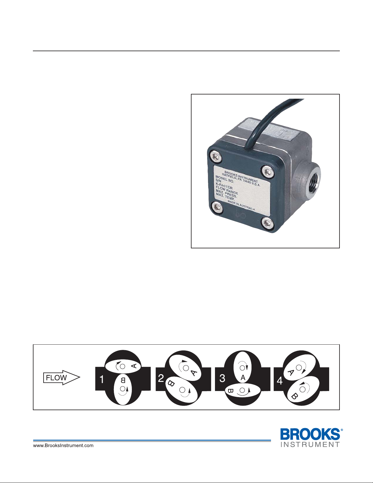
PRINCIPLE OF OPERATION
The oval meter is a positive displacement meter. As
the fluid being measured passes through the meter, it
rotates 2 oval gears in a measuring chamber to
displace a precision volume of fluid. A sensor detects
the gear rotation to determine displaced volume and
flow rate.
Fluid pressure rotates the oval gears, Figure 1. In
position 1, the fluid exerts a clockwise driving force on
Gear A.
Typical BM01 and BM02
There is no net driving force on Gear B. It is
perpendicular to the flow so the fluid forces are
balanced around the shaft. As the gears rotate to
position 2, the fluid begins to exert a force on Gear B.
At position 3, all the driving force is on Gear B. This
alternating driving force provides a smooth rotation of
almost constant torque.
The meter design minimizes the slippage between the
gears and the measuring chamber wall. As a result, the
oval meter is less affected than other designs by the
liquid's viscosity and lubricity.
Figure 1 Principle of Operation Chart
1
Page 2

Brooks® Models BM01 and BM02
Data Sheet
DS-PD-BM 01-02-eng
March, 2008
SPECIFICATIONS
Capacities
Viscosity BM01 BM02
< 5cP 1.32 to 26 gph 6 to 132 gph
(5 to 100 lph) (25 to 500 lph)
5 to 1,000cP 0.53 to 26 gph 4 to 132 gph
(2 to 100 lph) (15 to 500 lph)
Performance
Accuracy: +/- 1%
Repeatability: 0.03%
Typical meter performance and pressure drop:
Refer to Figure 2.
Ratings
Maximum working pressure:
PPS body: 75 PSIG (500 KPAG)
316 SS body: 150 PSIG (1000 KPAG)
Consult factory for higher pressure options.
Maximum working temperature:
PPS body and/or Rotors (Gears): 176° F (80° C).
316 SS body and Rotors (Gears): 248° F (120° C).
Ambient Temperature: -4° F to 104° F (-20° C to
+40° C).
Outputs
Note: each meter contains both switch types
Reed Switch
Detection Method: Reed Switch, Two wire SPST N/O contact.
Max. Voltage: 150 VDC maximum.
Contact Capacity: 0.25 AMPS
Rating 3 Watts.
Termination: 39 inch (1 meter) flying lead.
Nominal K-Factor:
Model BM01: 1000 p/l (3785.4p/gal)
Model BM02: 400 p/l (1514.2 p/gal)
Hall Effect Switch
Detection Method: Hall effect switch
Response Frequency: 1,000 Hz maximum
Output Pulse: Unfactored voltage pulse
Input/Output = 4.5 to 24 VDC (4.6 ~ 9 mA)
Open Collector 25 mA output NPN compatible with
digital logic. Reverse power protection.
Termination: 39 inch (1 meter) flying lead
Nominal K-Factor:
Model BM01: 1000 p/l (3785.4p/gal)
Model BM02: 400 p/l (1514.2 p/gal)
Meter Materials of Construction
Meter Body: PPS (Polyphenylene Sulfide) or 316
Stainless Steel.
Rotors(Gears):
BM01 / BM02 - PPS or 316 Stainless Steel.
316 Stainless Steel only for High Viscosity.
Rotors (Gears) Bearings:
BM01 / BM02 - Zirconia
Note: (PPS Rotors No Bearings Required)
Rotors (Gears) Shafts: 316 Stainless Steel or Optional
Hastalloy® C (PPS body only).
O-Rings: Standard Viton® fluoroelastomers or Optional
Teflon®.
Connections
¼ inch NPT (female)
Dimensions
Refer to Figure 3. For certified dimensional prints, contact
the factory.
Pressure Equipment Directive (97/23/EC)
Equipment falls under Sound Engineering Practice
(SEP) according to the directive.
2
ORDERING INFORMATION
To order please specify:
1. Model Number
2. Product (Process Fluid)
3. Viscosity
4. Maximum Operating Temperature
5. Maximum Operating Pressure
6. Operating Flow Ranges (Min., Max., & Normal)
7. Accessories Required
Page 3

Data Sheet
DS-PD-BM 01-02-eng
March, 2008
Figure 2 Typical Meter Error and Pressure Drop
Brooks® Models BM01 and BM02
Table 1 Brooks Model Code BM01 and BM02 Meters
MODEL BASIC MODEL SIZ E/RANGE
BM01B
BM02B
0.53 - 26 GPH / 2 - 100 LPH
4 -132 GPH / 15 - 500 LPH
CODE
R R
R S
SS
R H
SH
BODY/ROTOR MATERIAL
PPS (PO LYPHENYLENE SULFIDE) BODY & ROTOR (GEAR)
PPS BODY & 316 STAINLESS STEEL ROTOR (GEAR)
316 ST AINLESS ST EEL BODY & ROTOR (G EAR)
PPS BODY & 316 SS HIGH VISC. ROTOR (>10 00cP) BMO 2 ONLY
316 SS BO DY & HIGH VIS C. ROTOR (>1000cP) BM02 ONLY
CODE PULSER/DISPLAY
P
PULSE (BM01 = 3785 PPG BM02 = 1514 PPG)
CODE CONSTRUCTION
A
STAND ARD CONSTRUCTION
CODE PROCESS CONNECTION
2
1/4" NPT FEMALE
CODE OUTPUT
B
REED / HALL SWITCH (STANDARD)
CODE O-RINGS/SEALS
V
VITON (STANDARD)
K
TEFLON
CODE OPTIONS
A
NONE
C
HAST C SH AFTS
(REQUI RED WITH
PPS BODY/ROTOR)
BM01B
R S 1 A 2 B V A
3
Page 4

Brooks® Models BM01 and BM02
Data Sheet
DS-PD-BM 01-02-eng
March, 2008
Shipping Weight (Approximate)
Body BM01 BM02
PPS .53lbs. .53lbs.
.24Kg. .24Kg.
Stainless 1.32lbs. 1.32lbs.
For certified dimension prints, consult factory.
Figure 3 Dimensions
Steel .60Kg. .60Kg.
HELP DESK
In case you need technical assistance:
Americas
Europe +(31) 318 549 290 Within Netherlands 0318 549 290
Asia
Due to Brooks Instrument's commitment to continuous improvement of our products, all specifications are subject to
change without notice.
TRADEMARKS
Brooks .......................................................... Brooks Instrument, LLC
Hastelloy ............................................................Haynes International
Teflon.................................................. E.I. DuPont de Nemours & Co.
Tri-Clover ......................................................................Tri-Clover Inc.
Viton................................................DuPont Performance Elastomers
1-888-554-FLOW
+011-81-3-5633-7100
4
 Loading...