

Page 1
B R O O K F I
E L D E N G I N E E R I N G L A B O R AT O R I E S , I N C .
11 Comm e rce B oule va r d • M i dd le b o r o , MA 0 2 3 46 US A
ISO9001 CERTIFIED
T E L 5 0 8 - 9 4 6 - 6 2 0 0 o r 8 0 0 - 6 2 8 - 8 1 3 9 F A X 5 0 8 - 94 6 - 62 6 2
w w w . b r o o k f i e l d e n g i n e e r i n g . c o m
Boston • Chicago • London • Stuttgart • Guang zhou
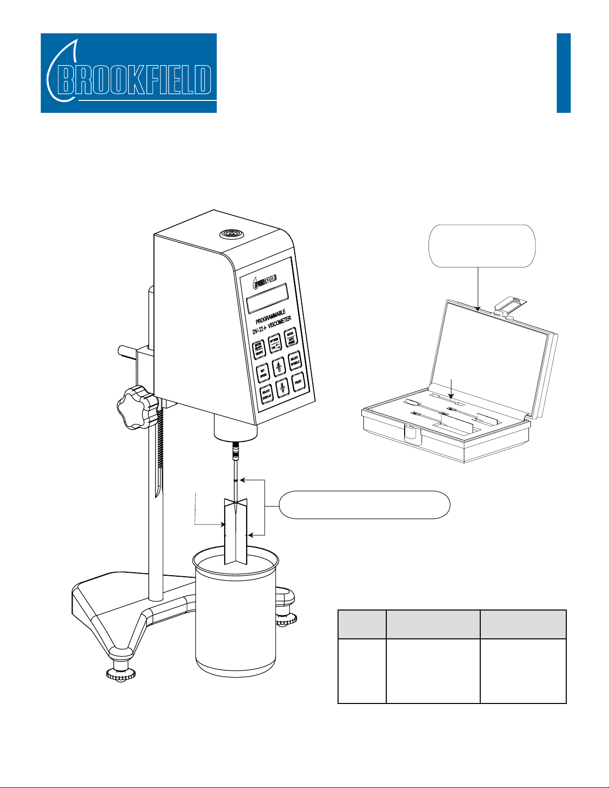
Vane Spindles
Primary Immersion Mark
Secondary Immersion Mark
Vane
Spindle
Choose the immersion mark which best suits
the size of container for your sample material.
Vane Spindle Set
includes 3 vane spindles
and storage case
Part No. SSVANE
(empty slot)
Table 1 - Vane Spindle Dimensions
Spindle
Vane Length
inches cm
Vane Diameter
inches cm
V-71 2.708 6.878 1.354 3.439
V-72 1.708 4.338 .853 2.167
V-73 .998 2.535 .499 1.267
V-74 .463 1.176 .232 .589
V-75 .632 1.61 .316 .803
Note: Sample container diameter should be at least twice (2x) the vane
diameter when possible. Sample container depth should provide
clearance, at the bottom, greater than or equal to vane spindle
diameter when possible.
Assembly & Operating Instructions
Manual No. M02-290-C0809
Vane spindles can be used with any standard Brookeld Viscometer/Rheometer. V-71, V-72, and V-73 are
supplied in the Vane Spindle Set (Part No. SSVANE). The V-74 and V-75 spindles are optional extras. The
small size of the V-74 vane spindle is ideal for testing small sample sizes and tting into sample containers
with small openings. However, limited surface area for spindle measurement geometry may make it more
challenging to obtain repeatable shear stress and viscosity values.
Page 2

Spindle
Torque Shear Stress Range Viscosity Range cP
Range Pa dyne/cm (mPa•s) @ 10 rpm
2
Table 2 - Spindle Range Data
V-71
V-72 LV .188-1.88 1.88-18.8 104.04 - 1040
V-73 LV .938-9.38 9.38-93.8 502 - 502000
V-74 LV 9.38-93.8 93.8-938 5.09 - 50900
V-75 LV 3.75-37.5 37.5-375 1996 - 19960
V-71 RV .5-5 5-50 262 - 2620
V-72 RV 2-20 20-200 1110 - 11100
V-73 RV 10-100 100-1000 5350 - 53500
V-74 RV 100-1000 1000-10000 54300 - 543000
V-75 RV 40-400 400-4000 21300 - 213000
V-71 HA 1-10 10-100 524 - 5240
V-72 HA 4-40 40-400 2220 - 22200
V-73 HA 20-200 200-2000 10700 - 107000
V-74 HA 200-2000 2000-20000 108600 - 1086000
V-75 HA 80-800 800-8000 42600 - 426000
V-71 HB 4-40 40-400 2096 - 20960
V-72 HB 16-160 160-1600 8880 - 88800
V-73 HB 80-800 800-8000 42800 - 428000
V-74 HB 800-8000 8000-80000 434400 - 4344000
V-75 HB 320-3200 3200-32000 170400 - 1704000
V-71 5XHB 20-200 200-2000 10480 - 104800
V-72 5XHB 80-800 800-8000 44400 - 444000
V-73 5XHB 400-4000 4000-40000 214000 - 2140000
V-74 5XHB 4000-40000 40000-400000 2172000 - 21720000
V-75 5XHB 1600-16000 16000-160000 852000 - 8520000
NOT RECOMMENDED FOR USE ON LV TORQUE
Notes: 1) 1 Pa = 10 dyne/cm2 2) 1cP = 1 mPa•s 3) Possibility of turbulence at speeds above 10 rpm may give artificially
higher viscosity readings 4) 5xHB torque available with DV-III Ultra Rheometer only.
Viscosity (cP) =
100
* TK * SMC * Torque
RPM
Table 3 - Viscometer Torque Constants
Model TK
LV 0.09373
RV 1
HA 2
HB 8
5xHB 40
Viscosity (cP) =
100
* TK * SMC * 2xTorque
RPM
Spindle Range Data
Table 4 - Spindle Multiplier Constants and Accuracy
Spindle SMC Accuracy*
V-71 2.62 ±2%
V-72 11.1 ±2%
V-73 53.5 ±2%
V-74 543 ±5%
V-75 213 ±3%
* Allowable error percentage is calculated on the
f
ull scale range viscosity for each spindle at a
defined speed.
Viscometer Operation
Attach the Vane Spindle to your Viscometer as shown in the illustration on page one (Note: spindles
have a left-hand thread for installation). Immerse the Vane Spindle into the uid past the top of the
Vane to the primary immersion mark on the shaft. Operate your Viscometer per the instructions in the
Operator’s Manual that came with your instrument. Record the instrument Speed (in RPM) and the
Torque Reading (as a percent). The Viscosity is calculated manually using the following equation:
where
RPM = Viscometer spindle speed in RPM
TK = Viscometer torque constant from Table 3
SMC = Spindle multiplier constant from Table 4
Torque = Viscometer torque (%) expressed as a
number between 0 and 100
If the secondary immersion mark (midpoint of the vane) is
chosen due to small container size, multiply the torque reading
by a factor of two (2).
 Loading...