

Page 1
B R O O K F I
E L D E N G I N E E R I N G L A B O R AT O R I E S , I N C .
Comm erce B oule va rd • M i dd le bo r o , MA 0 46 US A
ISO9001 CERTIFIED
T
E L
5 0 8 - 9 4 6 - 6 0 0 o r 8 0 0 - 6 8 - 8 9 F
A X
5 0 8 - 9 46 - 6 6
w w w . b r o o k f i e l d e n g i n e e r i n g . c o m
Bosto n • Chicag o • London • Stuttg art • Guan gzhou
Enhanced UL Adapter
PIVOT CUP,
BR-3
(PART OF
LAB VISCOMETER)
ULA-E SPINDLE
WITH COUPLING NUT,
YULA-15E -304 SS
YULA-15EZ-316 SS
MOUNTING
CHANNEL,
ULA-10E
MOUNTING
SCREW,
HT-99
CLAMPING
KNOB,
ULA-05EY
TUBE END CAP,
ULA-34
(NOT REQ’D WITH ULA-31EYZ
SAMPLE CHAMBER)
SAMPLE CHAMBER,
ULA-31EY
(304 s/s, open tube)
ULA-31EYZ
(316s/s, closed tube)
CLAMPING
COLLAR,
ULA-02E
WATER JACKET with
MOUNTING COLLAR,
ULA-49EAY
CONICAL PORTION
OF SHAFT
PIN
Assembly & Operating Instructions
No. M06-084
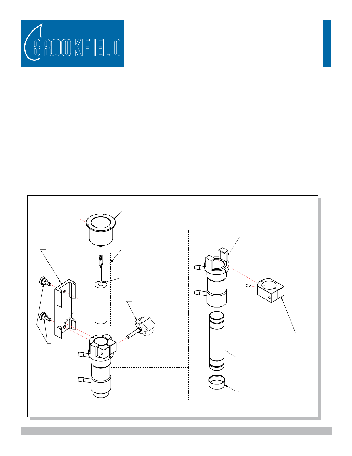
The Enhanced UL Adapter, shown in Figure 1, is a kit consisting of a spindle with coupling nut attached, sample
chamber, mounting channel, and water jacket with mounting collar. It is available in two versions: (1) with type
304 stainless steel suitable for most general purpose applications; (2) with type 316 stainless steel for use with
corrosive/acidic applications. All versions are shipped with the water jacket (ULA-49EAY) mounted on the
sample chamber.
The type 304 s/s UL Adapter (Part No. ULA-EY) may be used either as an “open tube” or “closed tube” system.
In the “open tube” method, the water jacket (ULA-49EAY) must be removed, allowing measurement in a beaker
or other suitable vessel. In the “closed tube” method, the sample is poured into the sample chamber with tube end
cap installed, which may be temperature controlled by direct immersion into a water bath or with the use of the
water jacket connected to a circulating water bath. The 316 s/s UL Adapter (Part No. ULA-EZY) has a closed
sample chamber with solid bottom and cannot be used as an open tube conguration.
The Enhanced UL Adapter may be ordered without the water jacket (Part No ULA-E). Check your sales order to
verify that you have received the correct conguration for your Enhanced UL Adapter.
Figure 1: Enhanced UL Adapter Assembly
Brookeld Engineering Laboratories Inc. - - Operating Instructions M06-084-A0507
Page 2
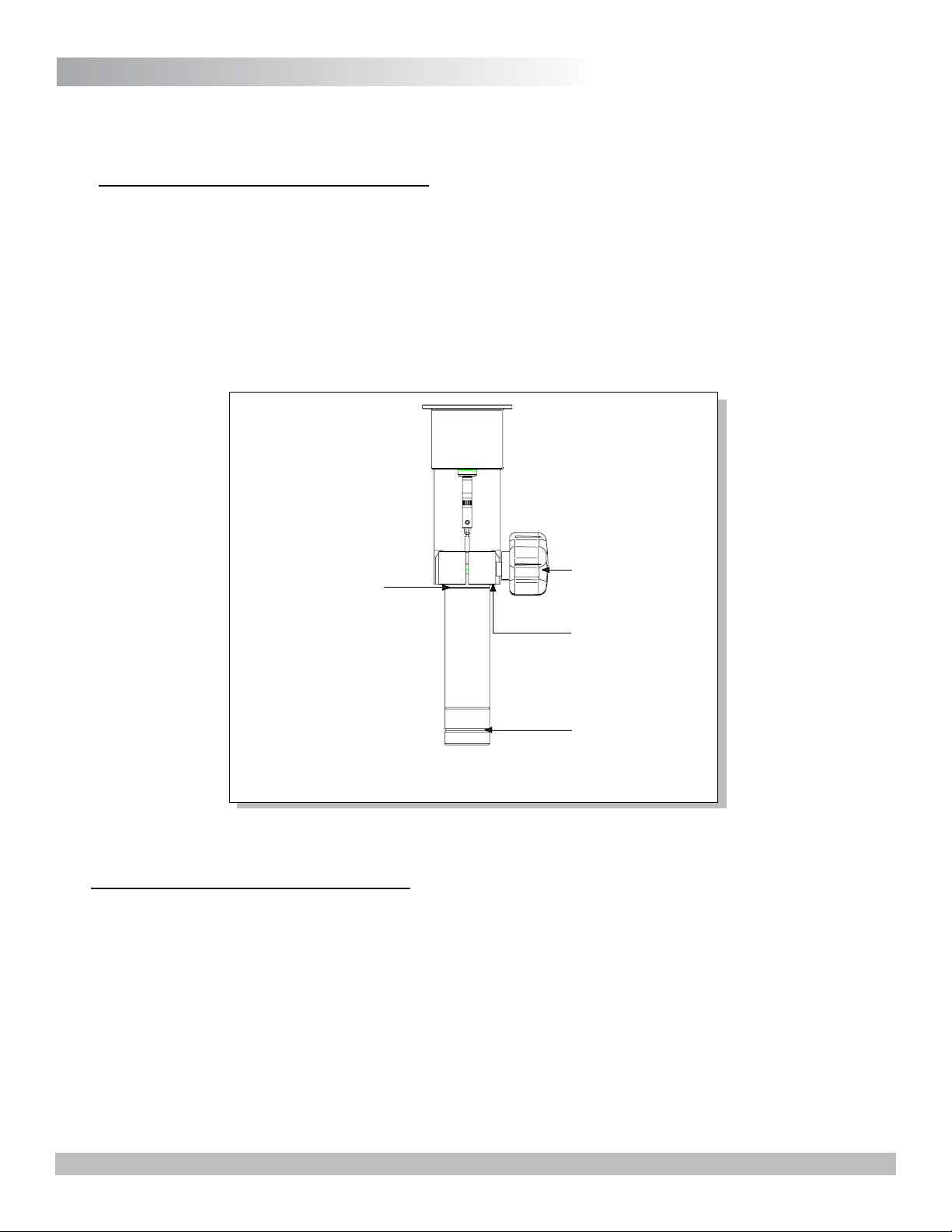
Assembly & Operation
CLAMPING COLLAR
CLAMPING KNOB
IMMERSION GROOVE
END CAP GROOVE
1. Attach the mounting channel to the viscometer by threading the upper mounting screw into the viscometer
pivot cup. Do not overtighten. The end of the mounting channel with the pin must be at the bottom, as
shown in Figure 1.
2. Open Tube Operation (#304 stainless steel)
The water jacket (ULA-49EAY) must be removed when the “open tube” method is used. This allows
measurement in a beaker or other container. The sample chamber must be inserted into the clamping collar
before immersion in sample uid. The top of the sample chamber should be ush with the top edge of the
clamping collar.
The clamping collar connects to the mounting channel as shown in Figure 1. The spindle with coupling nut
can be attached to the viscometer beforehand for easy handling. Observe the immersion groove located on
the outside of the sample chamber as shown in Figure 2.
3. Closed Tube Operation with Water Jacket
The UL Adapter may be used with the ULA-49EAY water jacket and a circulating water bath by connecting
the water jacket to the bath inlet and outlet ports (Figure 3). The tube end cap (ULA-34) is snapped over
the bottom end of the sample chamber before the sample is added. Be sure that it is securely seated in the
groove. Fill with 16 mL of sample uid. Insert the clamping collar into the mounting collar as shown in
Figure 1. Insert the sample chamber upwards into the water jacket and clamping collar. When fully inserted,
secure the sample chamber by tightening the clamping knob. Insert the spindle into the chamber. Attach the
clamping collar to the mounting channel. Connect the spindle coupling to the viscometer; note left hand
thread. Conrm that the uid level in the sample chamber covers the conical portion of the spindle shaft.
CAUTION: The spindle, sample chamber, and cap (if used) should be clean before use. The cap material
Brookeld Engineering Laboratories Inc. - - Operating Instructions M06-084-A0507
Figure 2: Sample Tube Immersion
Chamber Shown is #304 Stainless Steel
is low density polyethylene. Replace when damaged or loose.
Page 3

Fluid Recommended Recommended Note
Temperature Fluid Tubing
-10°C to 15°C TC-FLUID 2
1
ULA-45
R, 2
Do Not Use Gum
Rubber Tubing With
This Fluid
15°C to 65°C Water Gum Rubber
or Fluran
R
65°C to 100°C TC-FLUID 3
3
ULA-45 R Do Not Use Gum
Rubber Tubing With
This Fluid
Table 1
R
Fluran is a Registered Trademark of Norton Co.
1. Use only laboratory grade ethylene glycol. Do not use automobile anti-
freeze which contains materials that can damage the equipment.
2. Fluran tubing (5/16" ID) and clamps are offered in a kit, part # ULA-45A.
3. Do not use high viscosity oil. Recommended is 50 centipoise.
TEMPERATURE
BATH
BATH OUTLET
BATH INLET
VISCOMETER
PIVOT CUP
(on Viscometer)
WATER
JACKET
OUTLET
WATER
JACKET
INLET
T
UBE END CAP, ULA-34
SAMPLE CHAMBER
MOUNTING COLLAR
KNOB
Figure 3: ULA-49EAY Water Jacket Connections
4. Level the viscometer. General operating procedures for making viscosity measurements are described in the
viscometer operating instruction manual.
5. UL Adapter spindle factors are shown on page 4. The factor is used to calculate viscosity when using Dial
Reading Viscometers. All Brookeld digital model Viscometers and Rheometers calculate the viscosity value
automatically. The spindle entry code for the UL Adapter is 00.
Notes
• Maximum recommended viscosity for measurement with the UL Adapter is 2000 cP (mPa•s). If viscosity
exceeds 2000 cP, the material being measured may be too viscous to immerse the spindle into the sample
chamber; damage to internal parts of the viscometer may result.
• For tubing and uid recommendations when using a Constant Temperature Bath, refer to the table below:
Brookeld Engineering Laboratories Inc. - - Operating Instructions M06-084-A0507
Page 4

UL Adapter Factors
SP E CI ALI STS I N T HE
ME AS UR EM EN T AN D
CONTROL OF VISCOSITY
T
EL
508-946-600 or 800-68-89 FAX 50 8-9 4 6 -6 6
www. b r o o k f i e l d e ngine e r i n g . c o m
BROOKFIELD ENGINEERING LABORATORIES, INC.
Commerce Boulevard, Mi ddleboro, MA 0 46-0 USA
TYPE I
TYPE II
TYPE III
Threaded
Hole
The factor is used to calculate viscosity in units of centipoise (cP) or milli Pascal seconds (mPa•s) when using
Dial Reading or Model DV-I Viscometers. The Viscometer Dial Reading/DisplayValue x Factor = cP (mPa•s).
Factors are built-in for Digital Models DV-E, DV-I+, DV-I Prime, DV-II+ (all versions), and DV-III (all versions)
— no calculations required.
LV Models
RV-HA-HB Models
Shear Shear Factor
Speed Rate Speed Rate
(RPM) (sec-1) Factor (RPM) (sec-1) RV HA HB
60.0 73.38 0.1 100.0 122.30 0.64 1.28 5.12
30.0 36.69 0.2 50.0 61.15 1.28 2.56 10.24
12.0 14.68 0.5 20.0 24.46 3.20 6.40 25.60
6.0 7.34 1.0 10.0 12.23 6.40 12.80
3.0 3.67 2.0 5.0 6.12 12.80 25.60
1.5 1.83 4.0 4.0 4.89 16.00
0.6 0.73 10.0 2.5 3.06 25.60
0.3 0.37 20.0 2.0 2.45
1.0 1.22
0.5 0.61
Shear Rate Constant = RPM x .
When an older dial reading viscometer is used, the viscometer pivot
cup may need to be replaced with the
current design. If your viscometer
has a Type I or Type II pivot cup, the
cup should be replaced with a Type
III cup. Contact Brookeld or your
Brookeld agent for information.
Brookeld Engineering Laboratories Inc. - 4 - Operating Instructions M06-084-A0507
Figure 4: Pivot Cup Compatibility
 Loading...