

Page 1
BROOKFI
ELD ENGINEERING LABORATORIES, INC.
11 Commerce Boulevard • Middleboro, MA 02346 USA
UL Adapter
Assembly & Operating Instructions
No. M/91-080-I1003
T
EL
ISO9001 CERTIFIED
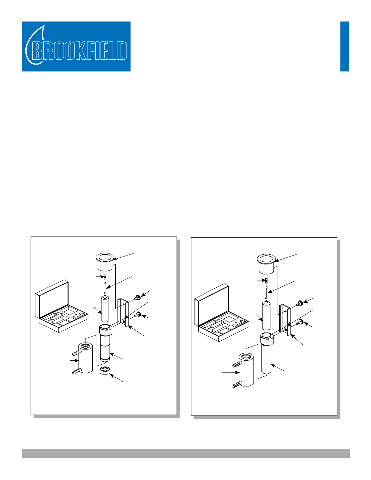
The UL Adapter is a kit consisting of a spindle, a sample tube, mounting channel, water jacket, coupling nut,
extension link and six end caps. It is available in two versions: (1) with type 304 s/s wetted parts as pictured
in Figure 1; (2) with 316 s/s wetted parts as pictured in Figure 2. All versions are shipped with the water jacket
(ULA-40Y) mounted on the sample tube.
The type 304 s/s* UL Adapter may be used as an “open tube” or “closed tube” system. In the “open tube”
method, the water jacket (ULA-40Y) must be removed, allowing measurement in a beaker or other suitable
vessel. In the “closed tube” method, the sample is poured into the sample tube. The closed tube may be
temperature controlled with the use of the water jacket.
The 316 s/s** UL Adapter is available only in the “closed tube” system. The closed tube system may be
temperature controlled with the use of the water jacket or the sample tube may be immersed into a temperature
bath.
508-946-6200 or 800-628-8139 FAX 508-946-6262
www.brookfieldengineering.com
Pivot Cup
mounted to
laboratory
viscometer base
ULA-36Y Case
ULA-40Y Water
Jacket
ULA-23A
Coupling
Nut
YULA-15
ULA
Spindle
ULA-31Y
Sample
Tube
ULA-34
Tube
End Cap
Extension
SXV-8
Link
HT-99
Mounting
Screw
Locating
Pin
ULA-28
Mounting
Screw
ULA-26Y
Locating
Channel Assembly
Figure 1: UL Adapter 304 s/s, Part No. ULA-Y
Pivot Cup
mounted to
laboratory
viscometer base
SXV-8
Extension
Link
Channel Assembly
ULA-35YZ
Sample
Tube
(closed tube)
Mounting
Locating
ULA-28
Mounting
ULA-26Y
Locating
HT-99
Screw
Pin
Screw
ULA-36Y Case
ULA-40Y Water
Jacket
ULA-23A
Coupling
Nut
YULA-15Z
ULA
Spindle
Figure 2: UL Adapter 316 s/s , Part No.ULA-ZY
*304 s/s denotes wetted parts are 304 stainless steel suitable for most general purpose applications.
**316 s/s denotes wetted parts are 316 stainless steel for use with corrosive acidic applications.
Brookfield Engineering Laboratories Inc. - 1 - Operating Instructions M/91-080-I1003
Page 2
Assembly & Operation
1. Attach the mounting channel to the viscometer by threading the upper mounting screw into the
viscometer pivot cup. Do not overtighten. The end of the mounting channel with the pin must be at the
bottom, as shown in Figure 1 and 2.
2. Assemble the ULA spindle, SXV-8 extension link, and ULA-23A coupling nut. Thread the coupling nut
onto the Viscometer coupling.
CAUTION: LEFT-HAND THREAD ON VISCOMETER AND COUPLING NUT!
3. Open Tube Operation:
The water jacket (ULA-40Y) must be removed when the open tube is used. This allows measurement
in a beaker or other container. The sample tube must be installed on the locating channel before
immersion in sample fluid.
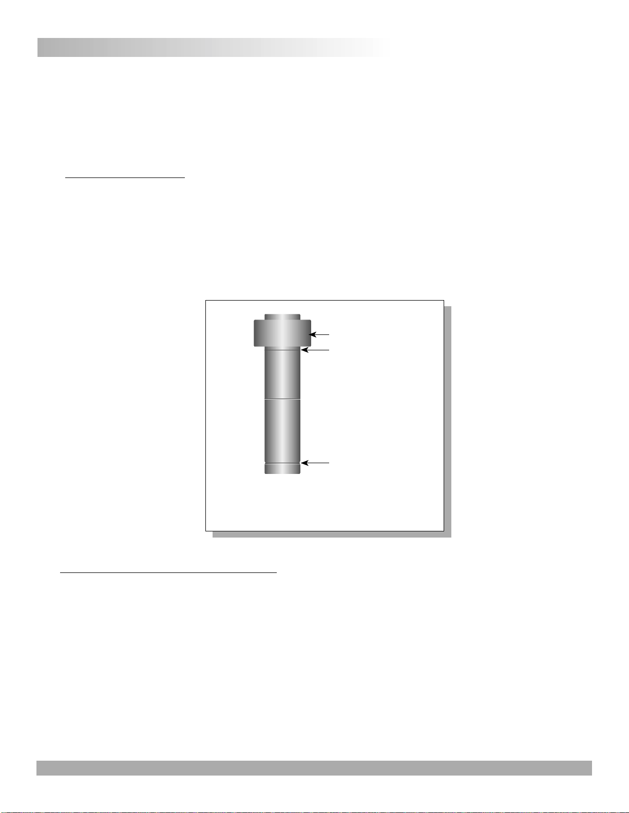
Observe the immersion grooves located on the outside of the tube below the collar (Figure 3). The top
groove is used with YULA-15 (#304 s/s) and YULA-15Z (#316 s/s) spindles. Be sure to immerse the tube
to the proper groove in order to obtain the correct spindle immersion depth.
Tube collar
Immersion groove
End cap groove
Figure 3: Sample Tube Immersion
and End Cap Grooves
4. Closed Tube Operation with Water Jacket:
The UL Adapter may be used with the ULA-40Y water jacket and a circulating water bath by connecting
the water jacket to the bath inlet and outlet ports (Figure 4). The tube end cap (ULA-34) is snapped over
the end of the tube before the sample is added. Be sure that it is securely seated in the groove. Fill with
16 mL of sample fluid before installing on locating channel.
CAUTION: (1) The spindle, tube, and cap (if used) should be clean before use. The cap material is low
density polyethylene. Replace when damaged or loose.
(2)When inserting the sample tube into the ULA-40Y Water Jacket, use gentle force to
prevent damage to O-rings and collar on inside diameter of ULA-40Y Water Jacket.
5. The closed tube system with 316 s/s wetted parts may also be used without the ULA-40Y water jacket by
immersing directly into the water bath.
Brookfield Engineering Laboratories Inc. - 2 - Operating Instructions M/91-080-I1003
Page 3

Sample
Tube
ULA-40Y
Water Jacket
ULA-34
Tube End
Cap
Bath
Outlet
PUMP
OUTLET
Water
Temp.
Bath
Bath
Jacket
Outlet
Bath
PUMP
INLET
Inlet
Jacket
Inlet
Figure 4: ULA-40Y water jacket connections
6. Add the sample to the chamber. Immerse the spindle into the chamber with the extension link and coupling
nut attached, then thread the water jacket to the locating channel assembly. Once that is done, thread the
coupling nut to the viscometer. This way the spindle is not hanging from the viscometer and it prevents
a mess with the sample. You can hook the extension link to the lip of the chamber to prevent the spindle
from dropping too far down.
7. Level the viscometer. General operating procedures for making viscosity measurements are described in
the viscometer operating instruction manual.
8. UL Adapter spindle factors are shown on page 4. The factor is used to calculate viscosity when using Dial
Reading or Model DV-I Viscometers. Model DV-I+/II/II+ Viscometers and DV-III/DV-III+ Rheometers
calculate the viscosity value automatically when the “cP display mode” is selected. The spindle entry
code for the UL Adapter is 00.
Notes
• Maximum recommended viscosity for measurement with the UL Adapter is 2000 cP (mPa•s). If viscosity
exceeds 2000 cP, the material being measured may be too viscous to immerse the spindle/tube, and damage
to internal parts of the viscometer may result.
• For tubing and fluid recommendations when using a Constant Temperature Bath, refer to the table below:
Fluid Recommended Recommended Note
Temperature Fluid Tubing
R, 2
-10°C to 15°C 50/50 Ethylene Fluran
Glycol/Water
1
This Fluid
15°C to 65°C Water Gum Rubber
or Fluran
65°C to 100°C Silicone Oil 3Fluran R Do Not Use Gum
Rubber Tubing With
This Fluid
Do Not Use Gum
Rubber Tubing With
R
R
Fluran is a Registered Trademark of Norton Co.
1. Use only laboratory grade ethylene glycol. Do not use automobile antifreeze which contains materials that can damage the equipment.
2. Fluran tubing (5/16" ID) and clamps are offered in a kit, part # ULA-45A.
3. Do not use high viscosity oil. Recommended is 50 centipoise.
Brookfield Engineering Laboratories Inc. - 3 - Operating Instructions M/91-080-I1003
Page 4

UL Adapter Factors
The factor is used to calculate viscosity in units of centipoise (cP) or milli Pascal seconds (mPa•s) when using Dial
Reading or Model DV-I Viscometers. The Viscometer dial reading/display value x Factor = cP (mPa•s).
LV Models
RV-HA-HB Models
Shear Shear Factor
Speed Rate Speed Rate
(RPM) (sec-1) Factor (RPM) (sec-1)RVHAHB
60.0 73.38 0.1 100.0 122.30 0.64 1.28 5.12
30.0 36.69 0.2 50.0 61.15 1.28 2.56 10.24
12.0 14.68 0.5 20.0 24.46 3.20 6.40 25.60
6.0 7.34 1.0 10.0 12.23 6.40 12.80
3.0 3.67 2.0 5.0 6.12 12.80 25.60
1.5 1.83 4.0 4.0 4.89 16.00
0.6 0.73 10.0 2.5 3.06 25.60
0.3 0.37 20.0 2.0 2.45
1.0 1.22
0.5 0.61
Shear Rate = RPM x 1.223
When an older dial reading visco-
TYPE I
meter is used, the viscometer Pivot
Cup may need to be replaced with
the current design. If your viscometer has a Type I or Type II pivot
cup, the cup should be replaced
TYPE II
with a Type III cup. Contact
Brookfield or your Brookfield agent
for information.
Threaded
Hole
TYPE III
Figure 5: Pivot Cup Compatibility
SPECIALISTS IN THE
MEASUREMENT AND
CONTROL OF VISCOSITY
BROOKFIELD ENGINEERING LABORATORIES, INC.
11 Commerce Boulevard, Middleboro, MA 02346-1031 USA
T
EL
508-946-6200 or 800-628-8139 FAX 508-946-6262
www.brookfieldengineering.com
Brookfield Engineering Laboratories Inc. - 4 - Operating Instructions M/91-080-I1003
 Loading...