

Broan SensAire, SensAire MS90, SensAire MS130 Series Manual
SENSAIRE® SERIES
MODELS MS90 & MS130
MOTION SENSING CEILING
FANS
READ AND SAVE
THESE INSTRUCTIONS
SERIE SENSAIRE
®
MODELOS MS90 Y MS130
VENTILADORES DE TECHO CON
SENSORES DE MOVIMIENTO
®
LEA Y CONSERVE
ESTAS INSTRUCCIONES
WARNING
TO REDUCE THE RISK OF FIRE, ELECTRIC
SHOCK, OR INJURY TO PERSONS, OBSERVE THE
FOLLOWING:
1. Use this unit only in the manner intended by the
manufacturer. If you have questions, contact the
manufacturer at the address or telephone number
listed in the warranty.
2. Before servicing or cleaning unit, switch power off
at service panel and lock the service disconnecting means to prevent power from being switched
on accidentally. When the service disconnecting
means cannot be locked, securely fasten a prominent warning device, such as a tag, to the service
panel.
3. Installation work and electrical wiring must be done
by a qualified person(s) in accordance with all applicable codes and standards, including fire-rated
construction codes and standards.
4. Sufficient air is needed for proper combustion and
exhausting of gases through the flue (chimney) of
fuel burning equipment to prevent backdrafting.
Follow the heating equipment manufacturer's
guideline and safety standards such as those published by the National Fire Protection Association
(NFPA), and the American Society for Heating, Refrigeration and Air Conditioning Engineers
(ASHRAE), and the local code authorities.
5. When cutting or drilling into wall or ceiling, do not
damage electrical wiring and other hidden utilities.
6. Ducted fans must always be vented to outdoors.
7. This unit may be used over a tub or shower enclosure when installed in a GFCI protected branch
circuit. (Ceiling installation only).
8. If this unit is to be installed over a tub or shower, it
must be marked as appropriate for the application.
9. Never place a switch where it can be reached from
a tub or shower.
10. Do not use this unit with any solid-state speed control device.
11. This unit must be grounded.
CAUTION
1. For general ventilating use only. Do not use to exhaust hazardous or explosive materials and vapors.
2. This product is designed for ceiling installation only.
DO NOT MOUNT THIS PRODUCT IN A WALL!
3. To avoid motor bearing damage and noisy and/or
unbalanced impellers, keep drywall spray, construction dust, etc. off power unit.
4. Please read specification label on product for further information and requirements.
PLAN THE
INSTALLATION
1. Choose the installation location.
The location of your SENSAIRE
portant. Follow these guidelines for best operation:
• Unit will respond to movement by people and
animals. After the unit stops sensing movement, it will stay ON for an additional 20 minutes (approx.). The length of ON time can be
adjusted from approx. 5-60 minutes.
• The sensor's viewing area is cone-shaped with
a diameter of approximately 11 ft. at floor level
in an 8 ft. high room. The viewing area can be
reduced to accommodate your installation.
• Refer to "USE AND CARE" section on page 3
for details about adjusting the time and viewing area.
®
fan is very im-
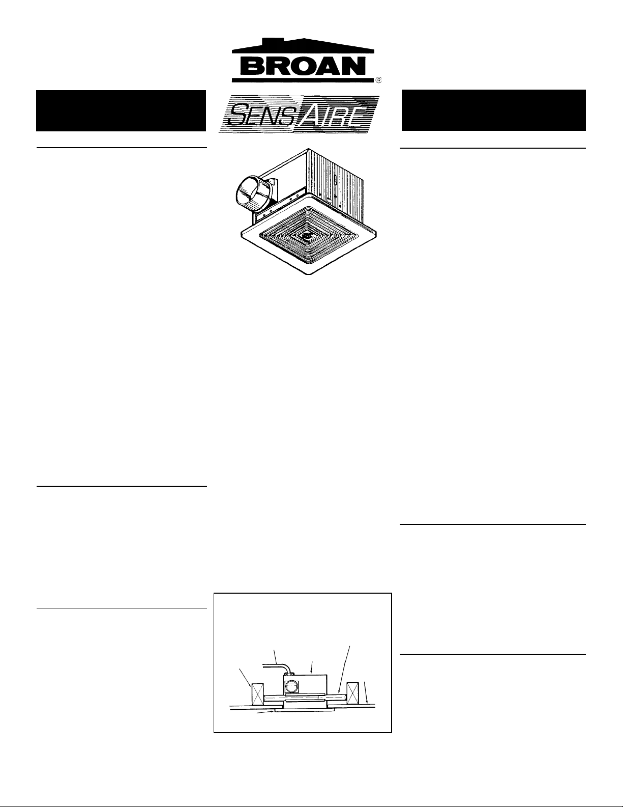
FIG. 1
CEILING
JOIST
VIGA DEL
TECHO
GRILLE
REJILLA
POWER
CABLE
CABLE DE
CORRIENTE
HOUSING
CARCASA
MOUNTING
BRACKET
SOPORTE DE
MONTAJE
DRYWALL
PARED
SECA
ADVERTENCIA
PARA REDUCIR EL RIESGO DE INCENDIO, DESCARGA
ELECTRICA O LESIONES PERSONALES, CUMPLA CON
LOS SIGUIENTES PUNTOS:
1. Solamente use esta unidad de la manera propuesta por
el fabricante. Si tiene alguna pregunta, póngase en
contacto con el fabricante en la dirección o teléfono
anotados en la garantía.
2. Antes de limpiar o de poner en servicio la unidad, apague
el interruptor en el panel de servicio, y asegure el panel
de servicio para evitar que se encienda accidentalmente.
Cuando el dispositivo para desconectar el servicio
eléctrico no puede ser cerrado con algún tipo de traba,
sujete fuertemente al panel de servicio, una etiqueta de
advertencia prominente.
3. El trabajo de instalación y el alambrado eléctrico deben
de llevarse a cabo por personal competente de acuerdo
con todos los códigos y las normas correspondientes,
incluyendo los códigos y normas de construcción contra
incendios.
4. Se requiere una cantidad de aire suficiente para la
combustión y expulsion de gases por la chimenea en el
equipo de quemado de combustible para evitar la
retrogresión de la llama. Siga las especificaciones del
fabricante del equipo de calefacción y las normas de
seguridad semenjantes a las publicadas, tales como los
publicados por la Asociación nacional de protección contra
incendios (NFPA por sus siglas en inglés), y la Sociedad
americana de ingenieros de calefacción, refrigeración y
aire acondicionado (ASHRAE), y los códigos de las
autoridades locales.
5. Cuando corte o taladre en una pared o techo, no dañe el
alambrado eléctrico ni otras instalaciones ocultas.
6. Los ventiladores conductos deben siempre ventilar hacia
el exterior.
7. Esta unidad puede ser usada encima de un baño o ducha
cuando esté instalada mediante un circuito paralelo
protegido por el GFCI.
8. Si esta unidad va a ser instalada encima de un baño o
ducha, tiene que tener impreso que es adecuada para
ese uso.
9. Nunca coloque un interruptor donde pueda ser alcanzado
desde un baño o ducha.
10. No use esta unidad con aparatos de estado sólido de
control de velocidad.
11. Esta unidad debe ser conectada a tierra.
PRECAUCION
1. Solamente para uso de ventilación general. No se use
para extraer materiales ni vapores peligrosos o explosivos.
2. Este producto está diseñado solamente para su instalación
en el techo. NO MONTE ESTE PRODUCTO EN UNA
PARED.
3. Para evitar daños al cojinete del motor y/o impuldores
ruidosos o desequilibrados, mantenga la fuente de
potencia lejos de rocíos de pared seca, de polvo de
construcción, etc.
4. Lea la etiqueta de especificaciones del producto para más
información y requisitos.
PLANIFICACION DE
LA INSTALACION
1. Elija la posición de instalación.
La posición de su ventilador SENSAIRE
importante. Siga estas instrucciones para un mejor
funcionamiento:
• La unidad responderá al movimiento de personas y
animales. Después de que la unidad deja de detectar
movimiento, continuará encendida durante unos 20
minutos aproximadamente. La duración del tiempo en
que la unidad permanece encendida se puede regular de 5 a 60 minutos (aproximadamente).
®
es muy
INSTALLER: Leave This Manual With The Homeowner. HOMEOWNER: Use and Care Information on Page 3.
INSTALADOR: Deje este manual con el dueño de la casa. DUEÑO DE LA CASA: Información del uso y cuidado en la página 3.
• Locate unit away from hallways and other high
traffic areas to prevent unwanted start-ups.
• Locate unit only on flat ceilings up to 12 feet
high for proper sensing.
• Locate unit in normal traffic flow. Unit will not
sense motion in remote areas of room.
The fan will operate most efficiently when located
where the shortest possible duct run and minimum number of elbows will be needed.
2. Plan the wiring.
Plan to supply the unit with proper line voltage
and appropriate power cable. Power cable should
be routed to the switch box first and then to the
unit (See wiring diagrams on page 3). Do not control this unit with speed control. Damage to the
sensor unit will result
Follow these basic steps when installing the unit:
• Nail housing to joists.
• Attach ductwork.
• Connect power cable.
• Install fan assembly.
• Fasten grille to housing. (FIG. 1)
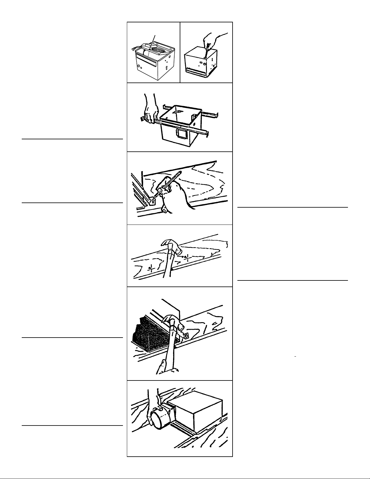
PREPARE THE FAN
1. Disengage the captive screw holding the fan assembly in place. Lift assembly from housing.
(FIG. 2)
2. Choose either the top or side of housing for electrical connection. Remove the knockout by bending it
back and forth to break tabs. (FIG. 3)
3. Slide adjustable mounting brackets into bracket
channels on housing. NOTE: Housing may be
mounted directly to joist using holes and slots provided. Use brackets for additional support. (FIG. 4)
INSTALL THE FAN
1. Choose the location for your fan. For best possible
performance, use the shortest possible duct run
and a minimum number of elbows.
2. Position unit between joists and extend mounting
brackets. Position brackets such that bottom edge
of housing will be flush with finished ceiling. Mark
the top of keyhole slot on all four mounting brackets. (FIG. 5)
3. Remove unit temporarily, and pound nails partially
into joists at all four marked locations. (FIG. 6)
4. Hang unit from nails. Use measuring guides on
corners of housing to check if unit will be flush with
finished ceiling. Pound nails tight. For wide joist
centers: A #8 x 3/8 self-tapping screw can be used
to join extended brackets together and create a
rigid mount. To ensure a noise-free mount, crimp
the bracket channels tightly around mounting
brackets. (FIG. 7)
5. Snap the damper/duct connector onto housing.
Make sure that tabs on the connector lock in housing slots and that gravity closes damper. (FIG. 8)
6. Install 4" round duct and extend duct to outside
through a roof or wall cap. Check damper to make
sure that it opens freely. Tape all duct connections
to make them secure and air tight.
WIRE THE FAN
1. The two most common methods of wiring this fan
are shown in Fig.9 and 10. Follow the one you
chose when you planned the installation.
NOTE: An extra deep single-ganged and/or
double-ganged box is usually required. Check
code requirements.
2. Remove wiring cover. Run electrical cable as directly as possible to unit. Do not allow cable to
touch sides or top of unit after installation is complete. Push all wiring into corner of unit. Replace
wiring cover.
3. Replace fan assembly and secure with captive
screw.
4. Plug wiring connectors into their receptacles
mounted in the wiring box.
ATTACH GRILLE
1. Squeeze grille springs together and insert springs
into slots in motor plate.
2. Push grille up against ceiling. (FIG. 11)
3. Turn on power and check fan operation.
FIG. 2
CAPTIVE SCREW
TORNILLO CAUTIVO
FIG. 4
FIG. 5
FIG. 6
FIG. 7
FIG. 8
FIG. 3
• El área de detección del sensor tiene forma de cono
con un diámetro de aproximadamente 3,35 metros
(11 pies) al nivel del suelo en una habitación de 2,44
metros (8 pies). El área de detección puede ser
reducida para acomodar su instalación.
• Haga referencia a la sección de “USO Y CUIDADO”
de la página 3 para detalles sobre cómo ajustar el
tiempo y la zona de detección.
• Sitúe la unidad alejada de pasillos y otras zonas de
mucho tráfico para evitar que se active
imprevistament.
• Coloque la unidad solamente en techos planos de
menos de 3,66 metros (12 pies) de altura para una
detección adecuada.
• Sitúe la unidad en flujo normal de tráfico. La unidad
no detectará movimiento en las partes distantes de
la habitación.
El ventilador funcionará de la forma más eficiente cuando
se sitúe donde se necesite la instalación más corta de
tubos de conducto y el menor número posible de codos.
2. Planificación del alambrado eléctrico.
Planifique el suministro de la unidad con el voltaje de
línea correspondiente y el cable de corriente adecuado.
El cable de corriente debe ser dirigido a la caja de
interruptores primero y luego a la unidad (Vea los
diagramas de conexión en la página 3). No controle esta
unidad con un control de velocidad. Esto puede ocasionar
daños a la unidad del sensor.
Siga los siguientes pasos básicos cuando instale esta
unidad.
• Clave la carcasa a las vigas o soportes.
• Coloque los ductos
• Conecte el cable de corriente
• Instale el conjunto del ventilador
• Sujete la rejilla a la carcasa (FIG. 1)
PREPARACION
DEL VENTILADOR
1. Desune el tornillo cautivo que asegura el conjunto del
ventilador. Extraiga el conjunto de la carcasa. (FIG. 2)
2. Elija la parte de arriba o el lado de la carcasa para hacer
las conexiones eléctricas. Quite el disco removible hacia
adelante y atrás hasta romper las pestañas. (FIG. 3)
3. Deslice los soportes ajustables de montaje para meterlos
en los canales correspondientes en la carcasa. NOTA: La
carcasa puede ser montada directamente a la viga usando
los agujeros y las ranuras provistos. Use los soportes para
apoyo adicional. (FIG. 4)
INSTALACION
DEL VENTILADOR
1. Elija el lugar para colocar el ventilador. Para asegurar el
mayor rendimiento, use la instalación más corta de tubos
de conducto y el mínimo de codos.
2. Coloque la unidad entre las vigas y extienda los soportes
de montaje. Sitúe los soportes de manera que el extremo
inferior de la carcasa esté a nivel con el techo acabado.
Marque la parte superior de la ranura en los cuatro
soportes de montaje. (FIG. 5)
3. Retire la unidad temporalmente, y clave los clavos
parcialmente en las vigas en las cuatro posiciones
marcadas. (FIG. 6)
4. Cuelgue la unidad de los clavos. Use las guías de medida
en las esquinas de la carcasa para comprobar si la unidad
está a nivel con el techo acabado. Clave los clavos hasta
el fondo. Si existen centros de viga anchos: se puede usar
un tornillo autoenroscable N
extendidos y crear una superficie de montaje rígida. Para
que la montura del ventilador no tenga ruidos, doble los
canales de los soportes fuertemente alrededor de los
soportes de montaje. (FIG. 7)
5. Coloque el conector del amortiguador/conducto,
presionándolo sobre la carcasa. Cerciórese de que las
pestañas en el conector se enganchen en las ranuras de
la carcasa y que la gravedad cierra el amortiguador. (FIG.
8)
6. Instale conducto redondo de 10,16 cm (4 plg.) y extienda
el conducto hacia el exterior a través de la cubierta del
techo o la pared. Compruebe que el amortiguador abre
libremente. Cubra con cinta adhesiva todas las conexiones
de los tubos de conducto para hacerlas seguras y
herméticas.
o
8 x 3/8 para unir los soportes
 Loading...