

Broan Sensaire, Sensaire HS120L Series Manual
::
bathroomsource
.com
Call 1-800-667-8721 anywhere in the US and Canada -
www.bathroomsource.com
SENSAIRE® SERIES
MODEL HS120L
HUMIDITY SENSING
FAN/LIGHT/NIGHT LIGHT
READ AND SAVE
THESE INSTRUCTIONS
WARNING
TO REDUCE THE RISK OF FIRE, ELECTRIC SHOCK,
OR INJURY TO PERSONS, OBSERVE THE FOLLOWING:
1. Use this unit only in the manner intended by the
manufacturer. If you have questions, contact the
manufacturer at the address or telephone number listed in the warranty.
2. Before servicing or cleaning unit, switch power
off at service panel and lock the service disconnecting means to prevent power from being
switched on accidentally. When the service disconnecting means cannot be locked, securely
fasten a prominent warning device, such as a tag,
to the service panel.
3. Installation work and electrical wiring must be
done by a qualified person(s) in accordance with
all applicable codes and standards, including firerated construction codes and standards.
4. Sufficient air is needed for proper combustion and
exhausting of gases through the flue (chimney) of
fuel burning equipment to prevent backdrafting.
Follow the heating equipment manufacturer’s guideline and safety standards such as those published
by the National Fire Protection Association (NFP A),
and the American Society for Heating, Refrigeration and Air Conditioning Engineers (ASHRAE), and
the local code authorities.
5. When cutting or drilling into wall or ceiling, do not
damage electrical wiring and other hidden utilities.
6. Ducted fans must always be vented to the outdoors.
7. This unit may be used over a tub or shower enclosure when installed in a GFCI protected branch
circuit (ceiling installation only).
8. If this unit is to be installed over a tub or shower, it
must be marked as appropriate for the application.
9. Never place a switch where it can be reached from
a tub or a shower.
10. Do not use this unit with any solid-state speed
control device.
11.This unit must be grounded.
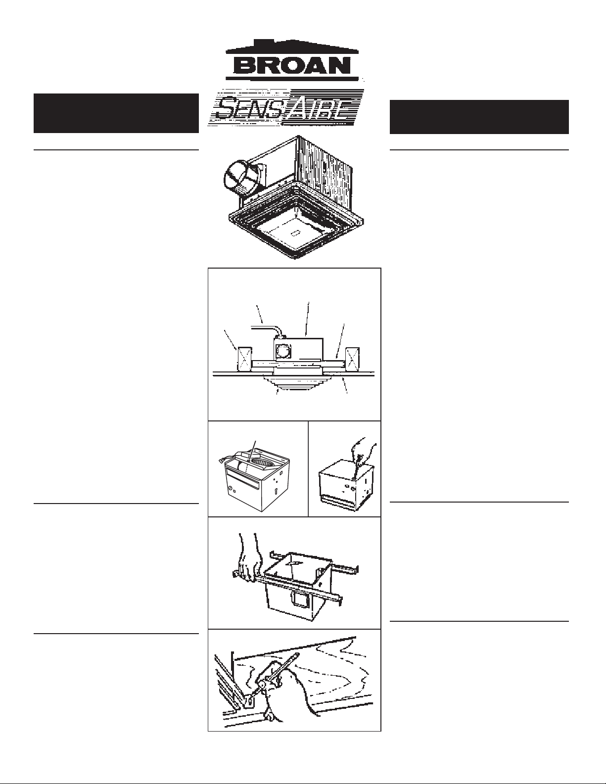
FIG. 1
CEILING
JOIST
VIGA DEL
CIELO
RASO
CAPTIVE SCREW
FIG. 2
TORNILLO CAUTIVO
POWER
CABLE
CABLE DE
POTENCIA
GRILLE
REJILLA
HOUSING
CAJA
MOUNTING
BRACKET
SOPORTE DE
MONTAJE
DRYWALL
PARED DE
YESO
FIG. 3
SERIE SENSAIRE
®
MODELO HS120L
SENSOR DE HUMIDAD
VENTILADOR LUZ/LUZ
®
NOCTURNA
LEA Y CONSERVE
ESTAS INSTRUCCIONES
ADVERTENCIA
PARA REDUCIR EL RIESGO DE INCENDIO, GOLPE
ELECTRICO, O HERIDA A PERSONAS, OBSERVESE
LO SIGUIENTE:
1. Use esta unidad solamente de la manera que se intenta
por el fabricante. Si usted tiene preguntas, póngase en
contacto con el fabricante a la dirección o número
telefónico que se encuentra en la garantía.
2. Antes de limpiar o de poner en servicio la unidad, apague
el interruptor en el panel de servicio, y asegure el panel
de servicio para evitar que se encienda accidentalmente.
Cuando el dispositivo para desconectar el servicio
eléctrico no puede ser cerrado con algún tipo de traba,
sujete fuertemente al panel de servicio, una etiqueta de
advertencia prominente.
3. El trabajo de instalación y cableado eléctrico deben
estar hechos por personal capacitado de acuerdo con
todos los códigos y estándares aplicables, incluyendo
códigos y estándares de construcción a prueba de
incendios.
4. Se necesita suficiente aire para la combustión apropiada
y extracción de gases por la chimenea del equipo que
quema combustible para evitar la retrogresión de la
llama. Siga las directrices del fabricante del equipo de
calefacción y estándares como los que publican la
Asociación Nacional de Protección Contra Incendio
(NFPA son sus siglas en Inglés)y la Asociación
Americana de Ingenieros de Ventilación, Refrigeración
y Aire Acondicionado, y los códigos de autoridades
locales.
5. Al cortar o taladrar en una pared o cielo raso, no dañe el
cableado eléctrico u otras instalaciones no visibles.
6. Ventiladores con conductos siempre deben extraer hacia
el exterior.
7. Esta unidad se puede usar arriba de una bañera o recinto
de ducha cuando se instala en un circuito protegido por
un protector de circuito con conexión a tierra en caso de
corto circuito (solamente instalación del cielo raso).
8. Si esta unidad se va a instalar arriba de una bañera o ducha,
debe estar marcada como apropiada para ese uso.
9. Nunca coloque un interruptor en un lugar que pueda ser
alcanzado desde una bañera o ducha.
10.No use esta unidad con ningún dispositivo de control de
estado sólido.
11.Esta unidad debe estar conectada a tierra.
CAUTION
1. For general ventilating use only. Do not use to
exhaust hazardous or explosive materials and
vapors.
2. This product is designed for installation in flat
ceilings only. DO NOT MOUNT THIS PRODUCT
IN A WALL.
3. T o avoid motor bearing damage and noisy and/or
unbalanced impellers, keep drywall spray, construction dust, etc. off power unit.
4. Please read specification label on product for further information and requirements.
PLAN THE
INSTALLATION
1. Choose the installation location.
The location of your SENSAIRE
portant. Follow these guidelines for best operation:
• The SENSAIRE
that responds to both increases in humidity and
to high humidity. The humidity sensor may turn
the fan ON when environmental conditions
change. If the fan continuously responds to
changing environmental conditions, "SENSITIVITY" adjustment may be required.
®
fan uses a humidity sensor
®
fan is very im-
FIG. 4
FIG. 5
PRECAUCION
1. Para uso de ventilación general. No lo use para extraer
materiales o vapores peligrosos o explosivos
2. Este producto está diseñado solamente para instalarse
en los techos planos. NO MONTE ESTE PRODUCTO
EN LA P ARED.
3. Para evitar daño a los cojinets del motor e impulsores
ruidosos y/o desbalanceados, mantenga la unidad de
potencia alejada de rocíos de yeso, polvo de contrucción,
etc.
4. Por favor lea la etiqueta de especificación para más
información y requisitos.
PLANIFIQUE LA
INST ALACION
1. Escoja el lugar de instalación
Dónde se sitúe su ventilador SENSAIRE
importante. Siga estas direcciones para mejor
funcionamiento:
• El ventilador SENSAIRE
que reacciona a aumentos de humedad y a humedad
alta. El sensor de humedad puede activar el ventilador
(ON) en ocasiones cuando hay combios
medioambientales. Si el ventilador responde
continuamente a condiciones medio-ambientales
combiantes, se puede necesitar ajustar la sensibilidad
(SENSITIVITY).
®
usa un sensor de humedad
®
es muy
INSTALLER: Leave This Manual With The Homeowner. HOMEOWNER: Use and Care Information on Page 3.
INSTALADOR: Deje este manual con el dueño de casa. DUEÑO DE CASA: Información del uso y mantenimiento en la página 3.
Broan at
::bathroomsource.com
1
is a division of
kitchen::
U N L I M I T E D
accessories

::
bathroomsource
.com
Call 1-800-667-8721 anywhere in the US and Canada -
www.bathroomsource.com
• Locate unit above (GFCI protected circuit required) or within 5 feet of shower head.
• Locate unit away from heating or cooling
sources which can affect humidity levels.
• Do not locate near window. Unit may respond
to the outdoor humidity level.
• Unit must be installed in ceiling to properly
sense moisture.
• Locate unit only on flat ceilings up to 12 feet
high for proper sensing.
The fan will operate most efficiently when located
where the shortest possible duct run and minimum number of elbows will be needed.
2. Plan the wiring.
Plan to supply the unit with proper line voltage
and appropriate power cable. Power cable should
be routed to the switch box first and then to the
unit (See FIGS. 9 & 10).
Do not control this unit with a speed control. Damage to the sensor unit will result.
Follow these basic steps when installing this unit:
• Nail housing to joist
• Attach ductwork
• Connect power cable
• Install fan assembly
• Fasten grille to housing
PREPARE THE FAN
1. Disengage the captive screw holding the fan assembly in place. Lift assembly from housing.
(FIG. 2)
2. Choose either the top or side of housing for electrical connection. Remove the knockout by bending it back and forth to break tabs. (FIG. 3)
3. Slide adjustable mounting brackets into bracket
channels on housing. NOTE: Housing may be
mounted directly to joist using holes and slots
provided. Use brackets for additional support.
(FIG. 4)
FIG. 6
FIG. 7
FIG. 8
INSTALL THE FAN
1. Choose the location for your fan. For best possible performance, use the shortest possible duct run and a minimum
number of elbows.
2. Position unit between joists and extend mounting brackets.
Position brackets such that bottom edge of housing will be
flush with finished ceiling. Mark the top of keyhole slot on all
four mounting brackets. (FIG. 5)
3. Remove unit temporarily, and pound nails partially into joist at
all four marked locations. (FIG. 6)
4. Hang unit from nails. Use measuring guides on corners of
housing to check if unit will be flush with finished ceiling. Pound
nails tight. For wide joist centers: A #8 x 3/8 self-tapping screw
can be used to join extended brackets together and create a
rigid mount. To ensure a noise-free mount, crimp the bracket
channels tightly around mounting brackets. (FIG. 7)
5. Snap the damper/duct connector onto housing. Make sure
that tabs on the connector lock in housing slots and that gravity closes damper. (FIG. 8)
6. Install 4” round duct and extend duct to outside through a roof
or wall cap. Check damper to make sure that it opens freely.
Tape all duct connections to make them secure and air tight.
WIRE THE FAN
1. The two most common methods of wiring this fan are shown
on the next page. Follow the one you chose when you planned
the installation. (FIGS. 9 & 10)
NOTE: An extra deep-ganged and/or double-ganged box
is usually required. Check code requirements.
2. Remove wiring cover. Run electrical cable as directly as possible to unit. Do not allow cable to touch sides or top of unit
after installation is complete. Push all wiring into corner of
unit. Replace wiring cover.
3. Replace fan assembly and secure with captive screw.
4. Plug wiring connectors into their receptacles mounted in the
humidity control assembly.
ATTACH GRILLE
1. Plug light/night light wiring into its receptacle.
2. Attach grille assembly with (2) phillips-head screws, provided.
DO NOT OVERTIGHTEN - Damage to grille may result. (FIG.
11)
3. Remove lens by gently pulling on edge. (FIG.11)
4. Install bulbs. Primary - 100W Max., Night Light - 7W type C7.
• Sitúe la unidad (se requiere un circuito protector de
conexión a tierra en caso de corto circuito) a no menos
de 1,52 m (5 pies) a la redonda de la ducha.
• Sitúe la unidad alejada de fuentes de calor o de
enfriamiento que puedan afectar los niveles de
humedad.
• No coloque la unidad cerca de una ventana. La unidad
puede responder al nivel de humedad exterior.
• La unidad debe ser instalada en el cielo raso para
detectar humedad de manera apropiada.
• Sitúe la unidad solamente en cielos rasos planos hasta
3,66 m (12 pies) de alto para detección apropiada.
El ventilador operará de la forma más eficiente cuando
se le sitúa donde se use el mínimo número posible de
conductos y el mínimo de codos.
2. Planifique el cableado
Planifique abastecer la unidad con el voltaje y el cable
de potencia apropiados. El cable de potencia se debe
traer primero a la caja de interruptores y luego a la unidad
(Véase FIGS. 9 y 10).
No controle esta unidad con un variador de velocidad.
La unidad sensora se puede dañar.
Siga estos pasos básicos al instalar la unidad:
• Clave la caja a las vigas
• Fije los conductos
• Conecte el cable de potencia
• Instale el conjunto del ventilador
• Fije la rejilla a la caja
PREPARACIÓN DEL
VENTILADOR
1. Desune el tornillo cautivo que mantiene el conjunto del
ventilador en su lugar. Saque el conjunto de la caja. (FIG.
2)
2. Elija la parte superior o un costado para conexiones
eléctricas. Saque el disco removible doblándolo para
atrás y para adelante hasta quebrar las lengüetas.
3. Deslice los soportes ajustables de montaje dentro de las ranuras de soporte en la caja. NOTA: la caja
se puede montar directamente a la viga usando los agujeros y ranuras que se incluyen. Use los
soportes para apoyo adicional. (FIG. 4)
(FIG. 3)
INSTALACION DEL VENTILADOR
1. Elija dónde va a situar su ventilador. Para asegurar el mayor rendimiento, use el mínimo número
posible de conductos y el mínimo de codos.
2. Coloque la unidad entre las vigas del cielo raso y extienda los soportes de montaje. Coloque éstos de
tal manera que el borde inferior de la caja esté a nivel con el cielo raso acabado. Marque la parte
superior de la ranura en los cuatro soportes de montaje. (FIG. 5)
3. Quite la unidad por unos momentos, y clave clavos parcialmente en las vigas, en las cuatro posiciones
marcadas. (FIG. 6)
4. Cuelgue la unidad de los clavos. Use las guías de medida en las esquinas de la caja para comprobar
si la unidad está a nivel con el cielo raso acabado. Clave los clavos hasta el fondo. Para vigas con
centro ancho: se puede usar un tornillo autoenroscable #8x3/8 para unir los soportes y crear un montaje
rígido. Para asegurar un montaje sin ruidos, doble los canales de los soportes alrededor de los soportes
de montaje. (FIG. 7)
5. Encaje el acople del amortiguador/conducto en la caja. Asegúrese que las lengüetas del acople cierren
en las ranuras de la caja y que el amortiguador cierre por gravedad. (FIG. 8)
6. Instale conducto redondo de 10,16 cm (4 pulg.) y extiéndalo hacia afuera por una cubierta de pared o
techo. Asegúrese que el amortiguador se abre con libertad. Ponga cinta en todas las uniones de
conductos para asegurarlas y hacerlas herméticas.
CABLEANDO EL VENTILADOR
1. Los dos métodos más comunes de cablear este ventilador se muestran abajo. Siga el que se escogió al
planear la instalación. (FIGS. 9 & 10)
NOTA: Normalmente se requiere una caja sencilla y/o doble extra profunda. Mire los requisitos del
código.
2. Saque la cubierta de la caja de cables. Tienda cable hasta la caja de la forma más directa que se pueda. No
permita que el cable toque los lados o la parte superior después que la instalación esté completa. Empuje
todos los cables dentro de una esquina de la unidad. Vuelva a colocar la cubierta de la caja.
3. Coloque de nuevo el conjunto del ventilador y asegure éste con el tornillo cautivo.
4. Enchufe los conectores en sus receptáculos en el conjunto del control de humedad.
FIJANDO LA REJILLA
1. Enchufe el cableado de la luz/luz nocturna dentro de su enchufe.
2. Fije el conjunto de la rejilla con 2 tornillos de cabeza phillips, se incluyen. NO LOS SOBREAPRIETE - Esto
puede dañar la rejilla. (FIG. 11)
3. Saque el lente tirando levemente del borde. (FIG. 11)
4. Ponga las bombillas. Primaria 100 vatios máximo. Luz nocturna 7 vatios tipo C7.
Broan at
2
::bathroomsource.com
is a division of
kitchen::
U N L I M I T E D
accessories
 Loading...