

Page 1

BR , AN
QML Series
at: www.broan.com
JRegister your product online J
Range Hoods
FOR DOMESTIC COOKING ONLY
WARNING WARNING
QML SERIES
Page 1
TO REDUCETHE RISK OF FIRE, ELECTRIC SHOCK, OR IN-
JURY TO PERSONS, OBSERVE THE FOLLOWING:
1. Use this unit only in the manner intended by the manufac-
turer. If you have questions, contact the manufacturer at the
address or telephone number listed in the warranty.
2. Before servicing or cleaning unit, switch power off at service
panel and lock the service disconnecting means to prevent
power from being switched on accidentally. When the ser-
vice disconnecting means cannot be locked, securely fasten
a prominent warning device, such as a tag, to the service
panel.
3. Installation work and electrical wiring must be done by a
qualified person(s) in accordance with all applicable codes
and standards, including fire-rated construction.
4. Sufficient air is needed for proper combustion and exhaust-
ing of gases through the flue (chimney) of fuel burning equip-
ment to prevent backdrafting. Follow the heating equipment
manufacturer's guideline and safety standards such as those
published by the National Fire Protection Association (NFPA),
and the American Society of Heating, Refrigeration and Air
Conditioning Engineers (ASHRAE), and the local code au-
thorities.
5. This product may have sharp edges. Be careful to avoid cuts
and abrasions during installation and cleaning.
6. When cutting or drilling into wall or ceiling, do not damage
electrical wiring and other hidden utilities.
7. Ducted fans must always be vented to the outdoors.
8. Use only metal ductwork.
9. Do not use this fan with any solid-state speed control device.
10.As an alternative, this product may be installed with the UL-
approved cord kit designated for the product, following in-
structions packed with the cord kit.
11.This unit must be grounded.
TO REDUCETHE RISK OFA RANGETOP GREASE FIRE:
1. Never leave surface units unattended at high settings.
Boilovers cause smoking and greasy spillovers that may ig-
nite. Heat oils slowly on low or medium settings.
2. Always turn hood ON when cooking at high heat or when
flamb_ing food (i.e. Crepes Suzette, Cherries Jubilee, Pep-
percorn Beef Flamb_).
3. Clean ventilating fans frequently. Grease should not be al-
lowed to accumulate on fan or filter.
4. Use proper pan size. Always use cookware appropriate for
the size of the surface element.
TO REDUCE THE RISK OF INJURY TO PERSONS IN THE
EVENT OF A RANGE TOP GREASE FIRE, OBSERVE THE
FOLLOWING:*
1. SMOTHER FLAMES with a close-fitting lid, cookie sheet,
or metal tray, then turn off the burner. BE CAREFUL TO
PREVENT BURNS. If the flames do not go out immediately,
EVACUATE AND CALL THE FIRE DEPARTMENT.
2. NEVER PICK UP A FLAMING PAN iyou may be burned or
spread the fire.
3. DO NOT USE WATER, including wet dishcloths or towels - a
violent steam explosion will result.
4. Use an extinguisher ONLY if:
A. You know you have a Class ABC extinguisher, and you
already know how to operate it.
B. The fire is small and contained inthe area where it started.
C. The fire department is being called.
D. You can fight the fire with your back to an exit.
* Based on "Kitchen Firesafety Tips" published by NFPA.
CAUTION
1. For indoor use only.
2. For general ventilating use only. Do not use to exhaust haz-
ardous or explosive materials and vapors.
3. To avoid motor bearing damage and noisy and/or unbal-
anced impeller, keep drywall spray, construction dust, etc.,
off power unit.
4. Do not use over cooking equipment greater than 60,000
BTU/hr.
5. Your hood motor has a thermal overload which will automati-
cally shut off the motor if it becomes overheated. The motor
will restart when it cools down. If the motor continues to shut
off and restart, have the hood serviced.
6. The bottom of the hood MUST NOT BE LESS than 18" and at
a maximum of 24" above cooktop for best capture of cooking
impurities.
7. Please read specification label on product for further infor-
mation and requirements.
F'N"_ If hood is to be installed non-ducted:
Purchase non-ducted filter (Model BPQTF) from your
local distributor or retailer.
Installer:Leavethis manual
withthe homeowner.
Homeowner:Cleaning, Maintenanceand
Operatinginstructionson page2.
Page 2
BR , AN
QML SERIES
Page 2
OPERATION
Always turn the hood ON before cooking in order to establish an
air flow in the kitchen. After turning off the range, let the hood run
for a few minutes to clear the air.
Operate the hood as follows:
I 0 II I 0 II
FAN SWITCH
I Turns fan on to LOW speed.
O Turns fan OFE
II Turns fan on to HIGH speed.
LIGHT SWITCH
I Turns light on to LOW intensity.
O Turns lightOFE
Stainless Steel Cleaning
DO:
• Regularly wash with clean cloth or rag soaked with warm water
and mild soap or liquid dish detergent.
• Always clean in the direction of original polish lines.
• Always rinse well with clear water (2 or 3 times) after cleaning.
Wipe dry completely.
• You may also use aspecialized household stainless steel cleaner.
DON'T:
• Use any steel or stainless steel wool or any other scrapers to
remove stubborn dirt.
• Use any harsh or abrasive cleansers.
• Allow dirt to accumulate.
• Let plaster dust or any other construction residues reach the
hood. During construction/renovation, cover the range hood to
make sure no dust sticks to the stainless steel surface.
Avoid: When choosing a detergent
• Any cleaners that contain bleach will attack stainless steel.
• Any products containing chloride, fluoride, iodide, bromide
will deteriorate surfaces rapidly.
• Any combustible products used for cleaning, such as
acetone, alcohol, ether, benzol, etc. are highly explosive and
should never be used close to a range.
LIGHT BULB REPLACEMENT
II Turns light on to HIGH intensity.
CLEANING AND
MAINTENANCE
Proper maintenance of the Range Hood will assure proper
performance of the unit.
Motor
The motor is permanently lubricated and never needs oiling. If
the motor bearings make excessive or unusual noise, replace
the motor with the exact service motor. The impeller should also
be replaced.
Grease Filter
The grease filter should be cleaned frequently. Use a warm
dishwashing detergent solution. Grease filter is dishwasher safe.
Clean all-metal filters in the dishwasher using a non-phosphate
detergent. Discoloration ofthe filter may occur if using phosphate
detergents, or as a result of local water conditions - but this will
not affect filter performance. This discoloration is not covered by
the warranty.
See "INSTALL FILTERS" section for removal and installation
instructions.
Non-ducted Recirculation Filter
The non-ducted recirculation filter should be changed every 6
months. Replace more often if your cooking style generates extra
grease, such as frying and wok cooking. See Step 15 on page 4,
for removal and installation instructions.
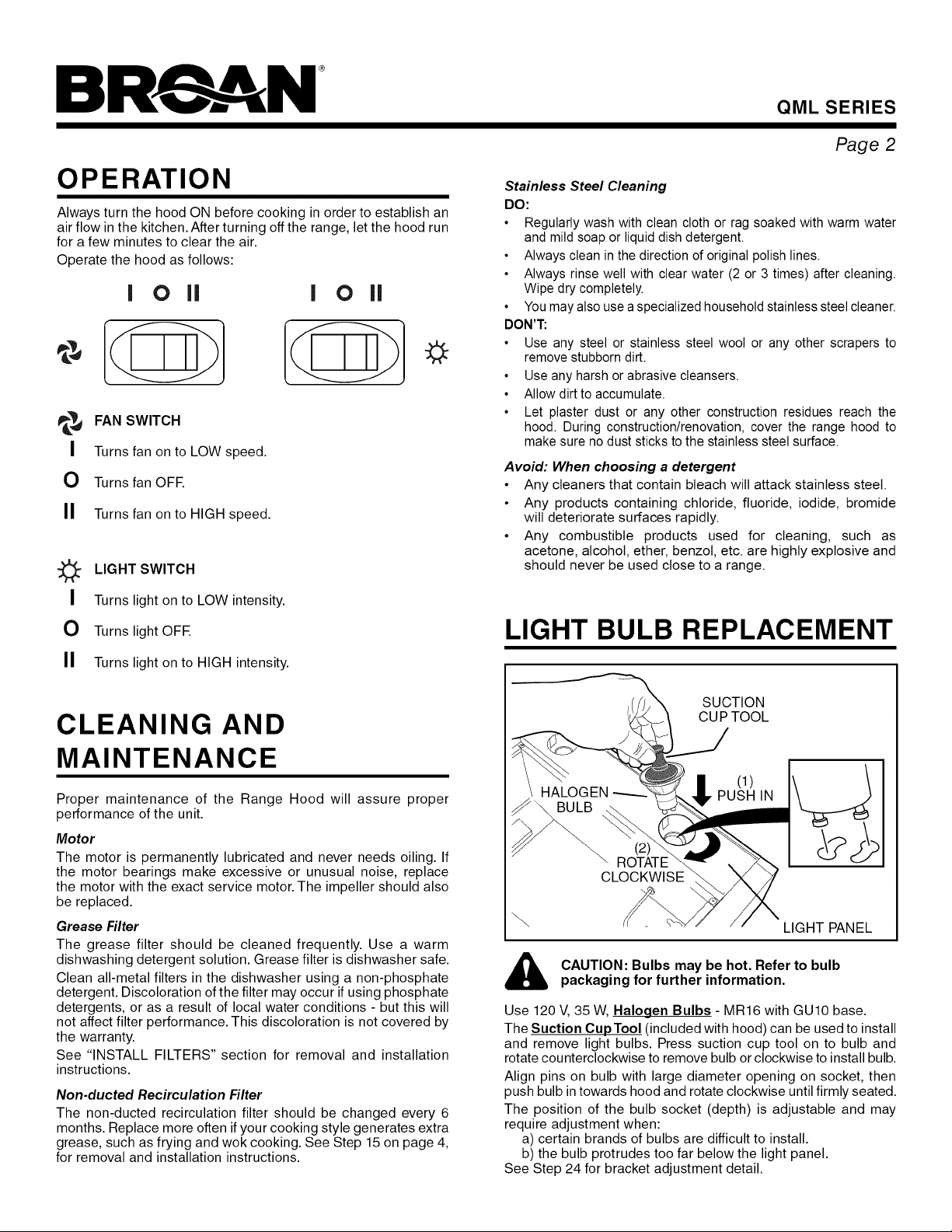
SUCTION
CUP TOOL
\ HALOGEN
"- ROTATE
CLOCKWISE
CAUTION: Bulbs may be hot. Refer to bulb
packaging for further information.
Use 120 V, 35 W, Halogen Bulbs - MR16 with GU10 base.
The Suction CupTool (included with hood) can be used to install
and remove light bulbs. Press suction cup tool on to bulb and
rotate counterclockwise to remove bulb or clockwise to install bulb.
Align pins on bulb with large diameter opening on socket, then
push bulb in towards hood and rotate clockwise until firmly seated.
The position of the bulb socket (depth) is adjustable and may
require adjustment when:
a) certain brands of bulbs are difficult to install.
b) the bulb protrudes too far below the light panel.
See Step 24 for bracket adjustment detail.
(1)
LIGHT PANEL
Page 3

BR., AN
QML SERIES
Page 3
INSTALL DUCTWORK
(Ducted Hoods Only)
ROOF CAP
CABINET
t
18" - 24" ABOVE
COOKING SURFACE
IT I Determine whether hood will discharge vertically (31A'' x
10" or 7" Round), or horizontally (31/4,' x 10" only).
r_ Decide where the ductwork will between the hood
and the outside.
Choose a straight, short duct run to allow the hood to
rq
perform most efficiently. Long duct runs, elbows and
transitions will reduce the performance of the hood. Use
as few of them as possible. Larger ductwork may be
required for best performance with longer duct runs.
F1 Install wall or roof Connect metal ductwork to
cap and work back towards the hood location. Use duct
tape to seal the joints between ductwork sections.
cap cap.
31A'' X 10" or
7" ROUND DUCT
(For vertical
discharge)
HOUSE WIRING
or Back of hood)
WALL CAP
31A'' X 10" DUCT
(For horizontal discharge)
run
PREPARE HOOD LOCATION
Use the proper diagram below for placement of ductwork
FI
and electrical cutout in cabinet or wall. For a non-ducted
installation, DO NOT cut a duct access hole.
HOOD MOUNTING SCREWS (5) VERTICAL DUCTING
_F 1315/16''(30''
l 31A'' X 10"
I.rOAB'NET_RONT
"n,:e I CABINET I_,. •
H_,!i BOTTOMI°_ 71/2"
I {,:'1 t I I VERTICALDUCT 1 91/21'1
/li_il_ I' ! I ACCESSHOLE lid
WOOD SHIMS t ELECTRICAL
recessed-bottom CENTER ACCESS HOLE
cabinets only) LINE (incabinet bottom)
WOOD SHIMS I 3W' X 10"
(recessed-bottom [ HORIZONTAL DUCTING
cabinets only) CABINET FRONT 3/4"
LL_L,, / Illl_l:__/j1/8" I]
/ 3¾"'| HORIZONTAL DUCT" "-,_CC&SS
CABINETJr_I
BOTTOM
•-1 315/16"(30''
HOOD t
MOUNTING CENTER ACCESS HOLE
SCREWS (5) LINE (in wall)
II
f
I
- - 1!-,- -
HOLE
ELECTRICAL
1
101/2"
HOOD MOUNTING SCREWS (5) DUCTING
315/18"(30" hood) 1
WOOD SHIMS t ELECTRICAL
(recessed-bottom CENTER ACCESS HOLE
cabinets only) LINE (in cabinet bottom)
* Note the extra wood shim and mounting screw near the
cabinet front, on the cabinet center line.
_1 Install 4 Hood Screws into shims/cabinet
according to proper diagram above. Do not tighten
completely. Do not install middle screw until Step 20.
Mounting
L 7-IN. ROUND
1
101/2 ''
Page 4
BR N
QML SERIES
CONTENTS
* FIND INSIDE
(1) GREASE
FILTER
(1) PARTS BAG** CONTAINING:
RD. HD. CUP TOOL
(5) #10 X 5/8" _ _1) BULB SUCTION
MOUNTING
SCREWS ** FIND PARTSBAGTAPEDTO
(1) 3W' X 10" (1) 7" ROUND
DAMPER / DUCT DUCT
CONNECTOR* CONNECTOR
INSIDEOF BOTTOM PANEL.
PREPARE THE HOOD
Remove all
FI
protective polyfilm
from the hood
(stainless steel
hoods only).
........ :cc:
Page 4
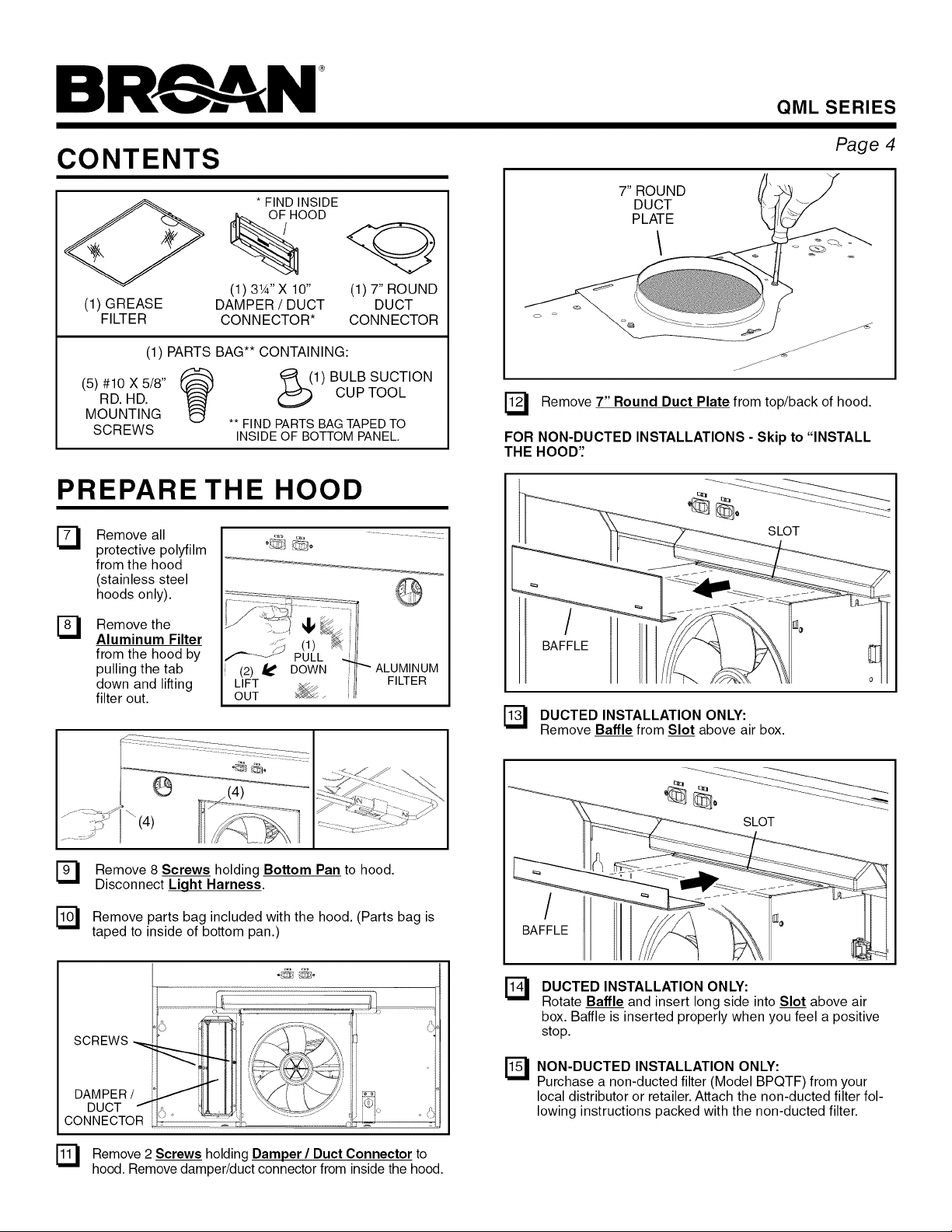
7" ROUND
DUCT
PLATE
"7 Remove 7" Round Duct Plate from top/back of hood.
FOR NON-DUCTED INSTALLATIONS - Skip to "INSTALL
THE HOOD':
SLOT
Remove the
FI
Aluminum Filter
from the hood by
pulling the tab
down and lifting
filter out.
Remove 8 Screws holding Bottom Pan to hood.
Disconnect Light Harness.
Remove parts bag included with the hood. (Parts bag is
taped to inside of bottom pan.)
IF j
(2) _' DOWN
LIFT
OUT
(1)
PULL
................................................................
SCREWS
DAMPER /
DUCT I-
CONNECTOR
FILTER
/
BAFFLE
7 DUCTED INSTALLATION ONLY:
Remove Baffle from Slot above air box.
SLOT
/
BAFFLE
DUCTED INSTALLATION ONLY:
El
Rotate Baffle and insert long side into Slot above air
box. Baffle is inserted properly when you feel a positive
stop.
[_ NON-DUCTED INSTALLATION ONLY:
Purchase a non-ducted filter (Model BPQTF) from your
local distributor or retailer. Attach the non-ducted filter fol-
lowing instructions packed with the non-ducted filter.
[_ Remove 2 Screws holding Damper / Duct Connector to
hood. Remove damper/duct connector from inside the hood.
Page 5
BR , AN
QML SERIES
Page 5
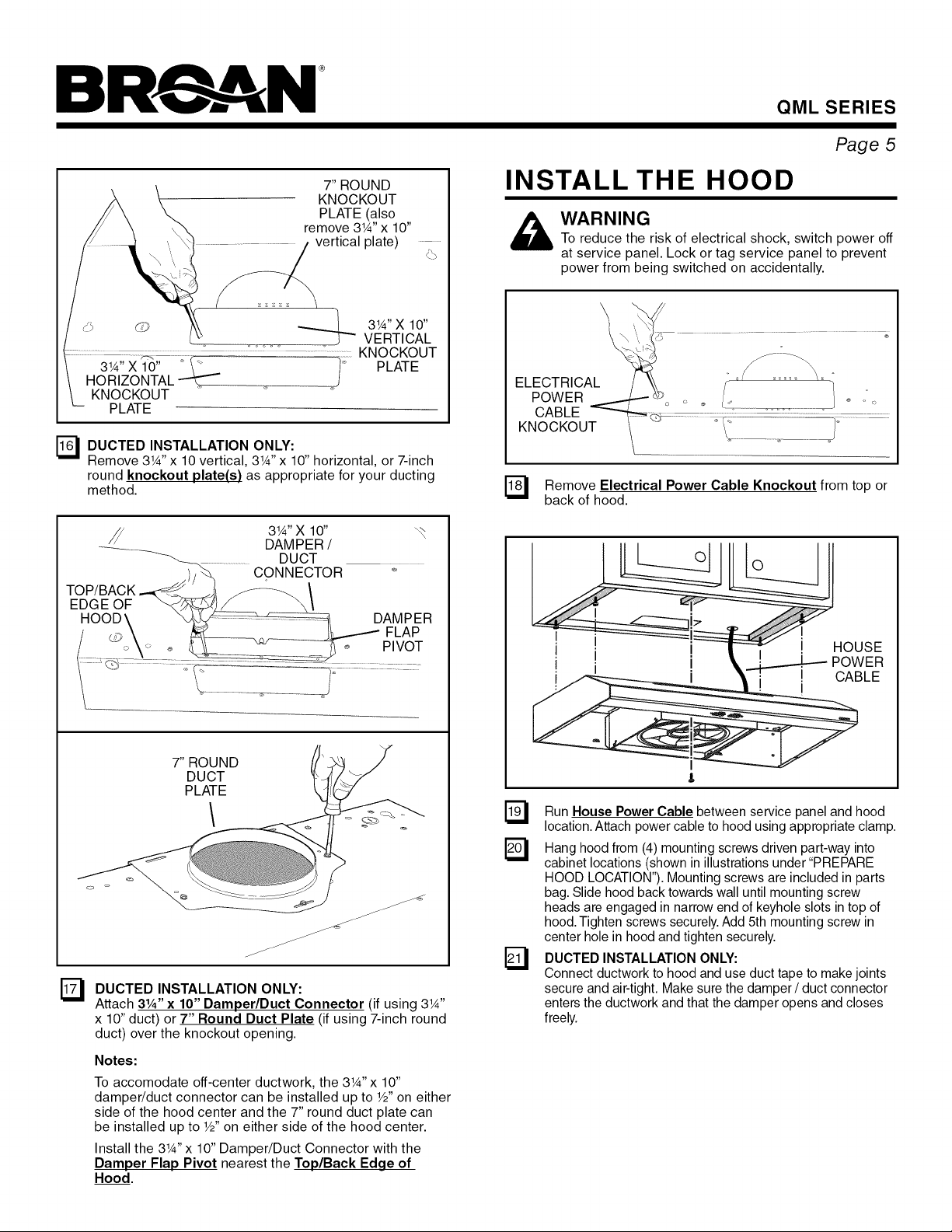
7" ROUND
KNOCKOUT
PLATE (also
remove 3W' x 10"
vertical plate)
VERTICAL
KNOCKOUT
KNOCKOUT
PLATE
r_ DUCTED INSTALLATION ONLY:
Remove 3W' x 10 vertical, 3W' x 10" horizontal, or 7-inch
round knockout plate(s) as appropriate for your ducting
method.
3W' X lO" _,_
DAMPER /
...................DUCT
TOP/BACK _ ........
H DAMPER
O o FLAP
l ...... ......... PIVOt
x:z .........
CONNECTO R _,
3W' X 10"
PLATE
INSTALL THE HOOD
_ ARNING
r_ Remove Electrical Power Cable Knockout from top or
To reduce the risk of electrical shock, switch power off
at service panel. Lock or tag service panel to prevent
power from being switched on accidentally.
back of hood.
HOUSE
POWER
CABLE
7" ROUND
DUCT
PLATE
DUCTED INSTALLATION ONLY:
El
Attach 3¼" x 10" Damper/Duct Connector (if using 3W'
x 10" duct) or 7" Round Duct Plate (if using 7-inch round
duct) over the knockout opening.
Notes:
To accomodate off-center ductwork, the 3W'x 10"
damper/duct connector can be installed up to W' on either
side of the hood center and the 7" round duct plate can
be installed up to W' on either side of the hood center.
Install the 3W' x 10" Damper/Duct Connector with the
Damper Flap Pivot nearest the Top/Back Edge of
Hood.
3 Run House Power Cable between service and hood
location. Attach power cable to hood using appropriate clamp.
r_ Hang hood from (4) mounting screws driven into
cabinet locations (shown in illustrations under "PREPARE
HOOD LOCATION"). Mounting screws are included in parts
bag. Slide hood back towards wall until mounting screw
heads are engaged in narrow end of keyhole slots in top of
hood. Tighten screws securely. Add 5th mounting screw in
center hole in hood and tighten securely.
_'_ DUCTED INSTALLATION ONLY:
Connect ductwork to hood and use duct tape to makejoints
secure and air-tight. Make sure the damper/duct connector
enters the ductwork and that the damper opens and closes
freely.
panel
part-way
Page 6

BR , AN
CONNECT THE WIRING
GROUND
SCREW
QML SERIES
Page 6
LAMP SOCKET
BRACKET
SCREWS
HOUSE
POWER CABLE
Connect House Power Cable to range hood wiring -
BLACK to BLACK, WHITE to WHITE, and GREEN or
BARE WIRE to Ground Screw. Replace electrical wiring
box cover.
Re-connect lamp wire harness and re-attach bottom panel
with (8) screws as shown inStep 10.
INSTALL LIGHT BULBS
SUCTION
CUP TOOL
\ HALOGEN
"- ROTATE
CLOCKWISE
(1)
To change the depth of bulb sockets:
- Remove bottom panel (See Step 10).
- Disconnect light harness.
- Loosen 2 Screws holding Lamp Socket Bracket to
Light Panel.
- Adjust socket/bracket to desired depth.
- Re-tighten screws securely.
- Re-attach light harness and replace bottom panel.
F_ DUCTED INSTALLATION ONLY:
Re-install aluminum filters removed in Step 9.
NON-DUCTED INSTALLATION ONLY:
Install non-ducted filter - purchased and assembled in
Step 15.
LIGHT PANEL
CAUTION: Bulbs may be hot. Always allow bulbs
to cool before removing them.
r_ install (2) Halogen Bulbs. Use 120 V, 35 W, shielded
halogen bulbs - MR16 with GU10 base.
NOTE: Suction Cup Tool (included with hood) can be
used to install and remove light bulbs.
Align pins on bulb with large diameter opening on socket,
then push bulb in towards hood and rotate clockwise until
firmly seated.
The position of the bulb socket (depth) is adjustable and
may require adjustment when:
a) certain brands of bulbs are difficult to install.
b) the bulb protrudes too far below the light panel.
Page 7

BR , AN
SERVICE PARTS
QML SERIES
Page 7
11t
3
/
14
j
KEY
NO. DESCRIPTION PART NO.
1
2
3
4
5
6
7
8
9
10
11
12
13
14
15
* Not illustrated. Purchase separately.
Order replacement parts by PART NO. - not by KEY NO.
BOTTOM PANEL ASSEMBLY, WHITE
BOTTOM PANEL ASSEMBLY, BLACK
BOTTOM PANEL ASSEMBLY, STAINLESS STEEL
SCREW PACKAGE #8-18 X 3/8 (2 SCREWS)
LAMP WIRE HARNESS
MOTOR WIRE HARNESS
AIR CHUTE
SWITCH, WHITE (2 REQUIRED)
SWITCH, BLACK (2 REQUIRED)
FAN BLADE (INCLUDES HAIRPIN CLIP)
HAIRPIN CLIP
PARTS BAG ASSEMBLY
FILTER, ALUMINUM
7" ROUND DUCT PLATE (INCLUDES MOUNTING HARDWARE)
3-1/4" X 10" DAMPER ASSEMBLY(INCLUDES MOUNTING HARDWARE)
MOTOR
HARDWARE BAG, LIGHT BRACKET
CABLE CLIP, WIRE HARNESS
BULB, 120V 35W MR16 GU10 BASE HALOGEN (2 REQUIRED)
NON-DUCTED FILTER
97018651
97018652
97018653
R602534
97018656
97018659
97018660
97017300
97018658
R531076
R99420635
97018623
R610092
R680508
R740014
99080666
97018665
99680044
99526798
99010317
Page 8

BR , AN
QML SERIES
Page 8
WARRANTY
One Year Limited Warranty
Broan-NuTone warrants to the original consumer purchaser of its products that such products will be free from defects in materials or
workmanship for a period of one (1) year from the date of original purchase. THERE ARE NO OTHER WARRANTIES, EXPRESS OR
IMPLIED, INCLUDING, BUT NOT LIMITED TO, IMPLIED WARRANTIES OF MERCHANTABILITY OR FITNESS FOR A PARTICULAR
PURPOSE.
During this one year period, Broan-NuTone will, at its option, repair or replace, without charge, any product or part which is found to be
defective under normal use and service. THIS WARRANTY DOES NOT EXTEND TO FLUORESCENT LAMP STARTERS, TUBES,
HALOGEN AND INCANDESCENT BULBS, FUSES, FILTERS, DUCTS, ROOF CAPS, WALL CAPS AND OTHER ACCESSORIES
FOR DUCTING. This warranty does not cover (a) normal maintenance and service or (b) any products or parts which have been
subject to misuse, negligence, accident, improper maintenance or repair (other than by Broan-NuTone), faulty installation or installation
contrary to recommended installation instructions.
The duration of any implied warranty is limited to the one year period as specified for the express warranty. Some states do not allow
limitation on how long an implied warranty lasts, so the above limitation may not apply to you.
BROAN-NUTONE'S OBLIGATION TO REPAIR OR REPLACE, AT BROAN-NUTONE'S OPTION, SHALL BE THE PURCHASER'S
SOLE AND EXCLUSIVE REMEDY UNDER THIS WARRANTY. BROAN-NUTONE SHALL NOT BE LIABLE FOR INCIDENTAL,
CONSEQUENTIAL OR SPECIAL DAMAGES ARISING OUT OF OR IN CONNECTION WITH PRODUCT USE OR PERFORMANCE.
Some states do not allow the exclusion or limitation of incidental or consequential damages, so the above limitation or exclusion may
not apply to you. This warranty gives you specific legal rights, and you may also have other rights, which vary from state to state. This
warranty supersedes all prior warranties.
To qualify for warranty service, you must (a) notify Broan-NuTone at the address or telephone number below, (b) give the model
number and part identification and (c) describe the nature of any defect in the product or part. At the time of requesting warranty
service, you must present evidence of the original purchase date.
Broan-NuTone LLC, 926 W. State Street, Hartford, Wisconsin 53027 www.broan.com 800-558-1711
99044758E
Page 9

BR , AN
Campanas
Serie QML
SOLAMENTE PARA COCINAR EN CASA
ADVERTENCIA ADVERTENCIA
Registre su producto en el I
I
sitio web www.broan.com
I
SERIE QML
P_gina 9
PARA REDUCIR EL RIESGO DE INCENDIO, DESCARGA ELI_CTRICA
O LESIONES CORPORALES, OBSERVE LO SIGUlENTE:
1. Use la unidad s61o de la manera indicada por el fabricante. Si tiene
preguntas, comuniquese con el fabricante a la direcci6n o al nt_mero
telef6nico que se incluye en la garantia.
2. Antes de dar servicio a la unidad o de limpiarla, interrumpa el
suministro electrico en el panel de servicio y bloquee los medios de
desconexi6n del servicio para evitar que la electricidad se reanude
accidentalmente. Cuando no sea posible bloquear los medios de
desconexi6n del servicio, fije firmemente una serial de advertencia
(como una etiqueta) en un lugar visible del panel de servicio.
3. Una o mas personas calificadas deben realizar el trabajo de
instalaci6n y el cableado electrico siguiendo todos los c6digos y
normas correspondientes, incluidos los c6digos y las normas de
construcci6n especificos para incendios.
4. Se necesita suficiente aire para que se Ileve a cabo una combusti6n
y una extracci6n adecuadas de los gases a traves del tubo de
humos (chimenea) del equipo quemador de combustible, con el fin
de evitar el contratiro. Siga las directrices y las normas de seguridad
del fabricante del equipo de calefacci6n, como las publicadas pot
la Asociaci6n Nacional de Protecci6n contra Incendios (National
Fire Protection Association, NFPA), y la Sociedad Americana de
Ingenieros en Calefacci6n, Refrigeraci6n y Aire Acondicionado
(American Society of Heating, Refrigeration and Air Conditioning
Engineers, ASHRAE), y las autoridades de los c6digos locales.
5. Este producto podria tenet bordes afilados. Trabaje con cuidado
para evitar cortes y abrasiones durante la instalaci6n y la limpieza.
6. AI cortar o perforar a traves de la pared odel techo, tenga cuidado
de no dafiar el cableado electrico ni otros servicios ocultos.
7. Los ventiladores en conductos siempre deben ventearse hacia el
exterior.
8. Utilice t_nicamente conductos metalicos.
9. No use este ventilador junto con ningt_n dispositivo de control de
velocidad de estado s61ido.
10. Como alternativa, se puede instalar este producto con el juego de
cable de alimentaci6n aprobado pot UL y disefiado para el producto,
siguiendo las instrucciones incluidas con el cable.
11. Esta unidad debe estar conectada a tierra.
PARA REDUCIR EL RIESGO DE INCENDIO PROVOCADO POR
GRASA PRESENTE EN LA ESTUFA:
1. Nunca deje desatendidas las unidades de la superficie cuando
esten en ajustes altos de calor. Los alimentos en ebullici6n provocan
derrames grasosos y con humo que se pueden incendiar. Caliente
el aceite lentamente en ajustes de calor bajo o medio.
2. Siempre ENCIENDA la campana cuando este cocinando a altas
temperaturas o flamee alimentos (pot ejemplo crepas Suzette,
cerezas Jubilee, bistec con pimienta flameado).
3. Limpie frecuentemente los ventiladores. No permita la acumulaci6n
de grasa en el ventilador ni en el filtro.
4. Use una cacerola del tamafio adecuado. Siempre use utensilios
de cocina que sean apropiados para el tamafio del elemento de la
superficie.
PARAREDUCIR EL RIESGO DELESIONES A LAS PERSONAS ENCASO DE
UN INCENDIO PRODUCIDO POR GRASA EN UNA ESTUFA, OBSERVE
LOSIGUIENTE*:
1. APAGUE LAS LLAMAS con una tapa de ajuste exacto, una charola para
galletas ouna bandeja de metal,y despu_s apague el quemador. PROCEDA
CONCUIDADO PARAEVlTAR QUEMADURAS. Si las llamas no se apagan
inmediatamente, EVACUE ELAREA Y LLAME A LOS BOMBEROS.
2. NUNCA LEVANTE UNA CACEROLA INCENDIADA porque podria sufrir
quemaduras o propagar el incendio.
3. NO USE AGUA, incluidos trapos o toallas de cocina mojados; puede
producirse una explosi6n violenta de vapor.
4. Use un extintor SOLO si:
A. Sabe que tiene un extintor clase ABC, y ya sabe c6mo usarlo.
B. El incendio es pequefio y esta.confinado al Area en la que se inici6.
C. Se esta Ilamando al Departamento de Bomberos.
D. Puedecombatirel incendioteniendo la espalda orientadahaciauna salida.
*Basado en "Consejos _itilesde seguridad en incendios en la cocina" ("Kitchen
Fire Safety Tips"), publicado por NFPA.
PRECAUCION
1. S61o debe usarse bajo techo.
2. S61o para usarse como medio de ventilaci6n general. No debe
usarse para la extracci6n de materiales o vapores peligrosos o
explosivos.
3. Para evitar dafios a los cojinetes del motor y rotores ruidosos o
desbalanceados, mantenga la unidad electrica al resguardo de
rociados de yeso, polvo de construcci6n, etc.
4. No use equipo para cocinar mayor de 60,000 BTU/hr.
5. Este motor de campana tiene una protecci6n contra sobrecargas termicas
que automaticamente apagara el motor en caso de sobrecalentamiento.
El motor reanudara su funcionamiento cuando se enfrie. Si el motor
continua apagandose y encendiendose, solicite servicio para la campana.
6. La parte inferior de la campana NO DEBE ESTAR A MENOS de
18 pulg. (45.7 cm) y a un mAximo de 24 pulg. (61 cm) pot arriba de
la estufa, para captar mejor las impurezas que surgen al cocinar.
7. Lea la etiqueta de especificaciones que tiene el producto para vet
informaci6n y requisitos adicionales.
Si la instalar sistema sin conductos:
campana se va a en un
Compre un filtro sin conductos (Modelo BPQTF) con su
distribuidor o tienda minorista local.
Avisoal instalador:Deje este manual
conel duefiode la casa.Avisoal duefio
de la casa:Enla p gina 10 encontrar
lasinstruccionesde limpieza,
mantenimiento y funcionamiento.
Page 10

BR., AN
SERIE QML
P4gina 10
FUNCIONAMIENTO
ENCIENDA siempre la campana antes de comenzar a cocinar,
con el fin de establecer un flujo de aire en la cocina. Despu6s de
apagar la estufa, deje que la campana funcione durante unos
cuantos minutos para despejar el aire.
Para hacer funcionar la campana, haga Io siguiente:
I 0 II I 0 II
@
INTERRUPTOR DELVENTILADOR
I Enciende el ventilador en velocidad BAJA.
O APAGA el ventilador.
II Enciende el ventilador en velocidad ALTA.
INTERRUPTOR DE LA LUZ
I Enciende la luz en intensidad BAJA.
O APAGA la luz.
II Enciende la luz en intensidad ALTA.
Lirnpieza del acero inoxidable
COSAS QUE PUEDE HACER:
• Regularmente, lave con una tela o trapo limpio remojado con agua
tibia yjab6n o detergente liquido para platos.
• Siempre limpie en la direcci6n de las lineas originales de pulido.
• Siempre enjuague bien con agua limpia (2o 3 veces) despues de la
limpieza. Deje totalmente seco.
• Tambien puede usar un limpiador casero especializado para acero
inoxidable.
CO8A8 QUE NO DEBE HACER:
• Usar lana de acero o acero inoxidable ni algQn otro tipo de raspador
para quitar mugre dificil de sacar.
• Usar limpiadores fuertes ni abrasivos.
• Dejar que se acumule la mugre.
• Dejar que el polvo forme plastas ni que quede en la campana
algen otro residuo de la construcci6n. Durante la construcci6n o la
renovaci6n, cubra la campana para estar seguro de que el polvo no
se pegue a la superficie de acero inoxidable.
Evite: AI elegir un detergente
• Todo limpiador que contenga blanqueador, pues atacara al
acero inoxidable.
• Productos que contengan cloruro, fluoruro, yoduro, bromuro,
pues deterioraran las superficies rapidamente.
• Todo producto combustible utilizado para la limpieza, como
acetona, alcohol, eter, benzol, etc., pues son altamente
explosivos y nunca se deben usar cerca de una estufa.
REEMPLAZO
DE LAS BOMBILLAS
LIMPIEZA Y
MANTENIMIENTO
El mantenimiento correcto de la campana de la estufa asegurara el
funcionamiento adecuado de la unidad.
Motor
El motor esta permanentemente lubricado y nunca necesitar_, ponerle
aceite. Si los cojinetes del motor estan haciendo ruido excesivo o
inusual, reemplace el motor con el motor de servicio exacto. Tambi_n
debe reemplazar el impulsor.
Filtro de grasa
El filtro de grasa se debe limpiar con frecuencia. Utilice una soluci6n
tibia de detergente para platos. El filtro de grasa se puede lavar en
lavaplatos. Limpie los filtros completamente met_.licos en la lavaplatos
con un detergente sin fosfatos. El filtro se puede decolorar si se utilizan
detergentes con fosfato o como resultado de la condici6n del agua
local, pero esto no afectar_, el desempe_o del filtro. Esta decoloraci6n
no est,. cubierta por la garantia.
Consulte la secci6n "INSTALAClON DE LOS FILTROS" para ver las
instrucciones de instalaci6n y desmontaje.
Filtro de recirculacion para sistemas sin conductos
El filtro de recirculaci6n para sistemas sin conductos se debe cambiar
cada 6 meses. C_.mbielo con mas frecuencia si su estilo de cocinar
genera mas grasa, como freir los alimentos o cocinar en un wok.
Consulte las instrucciones para quitar e instalar en el paso 15 de
la pagina 18.
HERRAMIENTA
DE VENTOSA
HACIA
(2)
GIRAR EN SENTIDO.
DE LASAGUJAS
DEL RELOJ
J\
calientes. Consulte la informacion adicional en los
PRECAUCION: Las bombillas podrian estar
paquetes de las bombillas.
Utilice bombillas de halbqeno de 120 V, 35 W (MR16 con base GU10).
La herramienta de ventosa (incluida con la campana) sirve para instalar
y quitar bombillas. Prensa herramienta de ventosa a la bombilla y girar a la
izquierda para quitar la bombilla o hacia la derecha para instalar la bombilla.
Alinee las clavijas de la bombilla con la abertura de diametro grande en
el recept_.culo, empuje la bombilla hacia la campana y luego gire hacia la
derecha hasta que este firmemente asentada.
La posici6n del receptaculo de la bombilla (profundidad) es ajustable, y
podria necesitar ajuste cuando:
a) Ciertas marcas de bombillas sean dificiles de instalar.
b) La bombilla sobresalga demasiado por debajo del panel de labombilla.
Vea el paso 24 para el detalle soporte de ajuste.
PANEL DE
ILUMINACION
Page 11

BR., AN
SERIE QML
P4gina 11
INSTALE EL SISTEMA
DE CONDUCTOS
($61o campanas para
sistemas con conductos)
TAPA DE TECHO
PLAFON
t
DE 18 a 24 PULG.
(45.7 a 61 CM) POR ENCIMA DE
LA SUPERFICIE DE COCINADO
Determine si la descarga de la campana va a ser vertical
rq
(conducto de 31Ax 10 pulg. [8.3 x 25.4 cm] o redondo
de 7 pulg. [17.8 cm]) u horizontal (s61o conducto de
31Ax 10 pulg. [8.3 x 25.4 cm]).
Decida d6nde instalara el conducto entre la campana y
el exterior.
Elija un conducto recto y corto para permitir que la
rq
campana funcione mas eficientemente. Los tramos
largos de conductos, codos y transiciones reduciran
el desempe_o de la campana. Use tan pocos de
ellos como sea posible. Es posible que se requieran
conductos m_.sgrandes para un mejor funcionamiento
con tramos mas largos de conductos.
Instale la tapa para pared o para techo. Conecte un
E]
conducto metalico en la tapa y trabaje hacia atras,
hacia la ubicaci6n de la campana. Use cinta para
conductos para sellar las uniones entre las secciones
de conductos.
CONDUCTO DE
31A x 10 pulg. (8.3 x 25.4 cm) o
CONDUCTO REDONDO
de 7 pulg. (17.8 cm)
(para descarga vertical)
CABLEADO ELECTRICO
DE LA CASA
;erior o
posterior de la campana)
CONDUCTO DE
31/4x 10 pulg.
(8.3 x 25.4 cm)
(para descarga horizontal)
PREPARE EL LUGAR DONDE
SE VA A INSTALAR LA
CAMPANA
Guiese por el diagrama correspondiente (a continuaci6n)
rq
para colocar los conductos y hacer el corte exacto para
la conexi6n elOctrica en el gabinete o en la pared. Para
instalaciones en sistemas sin conductos, NO haga
ningt]n orificio de acceso para conducto.
TORNILLOS DE MONTAJE
DE LA CAMPANA (5)
pulg (354 crn)
(32 cm)
t
CUNAS DE MADERA
(s01o gabinetes
de parte inferior empotrada)
CUNAS DE MADERA 31AX 10PULG.(8.3X 25.4CM]
(sologabinetes de parte FRENTE DEL 3/4pulg.
inferiorempotrada) GAB NETE., (1.9cm) I
,h"_ , , i ,,_pu,01 , ii
L|NEA PARA CABLES ELECTRICOS
CENTRAL (en la parte inferior del gabinete)
/ I /°32c;'L__i II
CONDUCTO VERTICAL DE
31AX 10PULG. (8.3 X 25.4 CM
I ] 315/16 pulg (354 cm)
l OEACCES
t ORIFICIO
CONDUCTOHORIZONTALDE
II L-----I_I II
- - - _'_ - - 1J, - - _ 1
/°.°_3_I _o_ouo_oHO_,ZO._
PARTE 5 V4pulg. l _5 Y4 pulg. I
INFERIOR I_'_3'3cm_ CmT_l
DEL GABINETE 171/2pulg. (19.1
__ 1315/16 pulg. (35.4 cm) _ 1315/16 pulg. (35.4 cm)
campana de 30 pulg./76.2 cm) I(campana de 30 pulg
TORNILLOS DE LiNEA ACCESO PARA
MONTAJE DE CABLES ELECTRICOS
LACAMPANA (5) CENTRAL (en la pared)
TORNILLOSDEMONTAJE DE 7 PULG. (7.8 CM)
DE LA CAMPANA (5)
_ 1315/16 pulg (354 cm) _ 1315/16 pulg (354 cm) ,__1
oampana do 30 I ulg/76 2 crr91 (_.,r,_,N_,de 30 pulg/16 2 cm) I
CUNAS DE MADERA t
(s01o gabinetes de L|NEA
parte inferior empotrada) CENTRAL
* Observe la cuba de madera adicional y el tornillo de
montaje cerca del frente del gabinete, sobre la linea central
del gabinete.
7 Instale 4 tornillos de de la
las calzas/gabinete, de acuerdo con el diagrama
correspondiente. No apriete totalmente. No instale el
tornillo de en medio hasta el paso 20.
I' ORIFICIO DE
CONDUCTO REDONDO
I I
ORIFICIO DE ACCESO
PARA CABLES ELECTRICOS
(en la parte inferior del gabinete)
montaje
campana
!
en
(267 cm)
Page 12

BR , AN
SERIE QML
CONTENIDO
* ENCUENTRA EN EL INTERIOR
_ (1)_CAMPANA.
CONECTOR CONECTOR
(1) FILTRO
DE GRASA
(1) BOLSA DE PIEZAS** QUE CONTIENE:
MONTAJE DE CABEZA DE VENTOSA PARA
REDONDA #10 X LAS BOMBILLAS
(5) TORNILLOS DE I_ (_ (1) HERRAMIENTA
5/8 PULG.
PARA REGULADOR/ PARA CONDUCTO
CONDUCTO DE 31A X 10 REDONDO DE
PULG. (8.3 X 25.4 CM)* 7 PULG. (17.8 CM)
** ENCUENTRA LA BOLSA DE PIEZAS CON
CINTA AL INTERIOR DEL PANEL INFERIOR.
PREPARE LA CAMPANA
Quite todo el forro
rq
de pl_.stico protector
de la campana
(t3nicamente
campanas de
acero inoxidable).
Retire el filtro de
E]
aluminio de la
campana jalando
la lengQeta hacia
abajo y levantando
el filtro.
_ (1) JALAR
(2) lr_ ABA,JO
LEVAN'[AR
HACIA
FUERA
HACIA
FILTRO DE
ALUMINIO
P_gina 12
PLACADEL
CONDUCTO
REDONDO
DE7 PULG. (17.8CM)
7 Retire la placa del conducto redondo de 7 pulq. (17.8 cm)
de la parte superior/trasera de la campana.
PARAINSTALACIONESSIN CONDUCTOS: pase
directamente al paso "INSTALE LA CAMPANA';
RANURA
DEFLECTOR
Quite los 8 tornillos que sostienen el recipiente inferior a la
campana. Desconecte el arn_s de las luces.
Retire la bolsa de piezas incluida con la campana. (Bolsa de
piezas se pega al interior del recipiente inferior.
TORNILLOS ._
CONECTOR DEL
REGULADORf
DETIRO/
CONDUCTO
r_ Quite los 2 tornillos sujetan el conector del requlador de
tiro/conducto a la campana. Quite el conector del regulador de
tiro/conducto del interior de la campana.
que
...............L° o
r_ UNICAMENTE EN INSTALACIONES CON CONDUCTOS:
Retire el deflector de la ranura arriba de la caja de aire.
I
RANURA
DEFLECTOR
UNICAMENTE EN INSTALACIONES CON CONDUCTOS:
FI
Gire el deflector e inserte el lado largo en la ranura arriba
de la caja de aire. El deflector se inserta adecuadamente
cuando siente un tope positivo.
[_ ONICAMENTE EN INSTALAClONES SIN CONDUCTOS:
Compre unfiltro sin conductos (Modelo BPQTF) con su
distribuidor o tienda minorista local. Conecte el filtro sin
conductos siguiendo las instrucciones incluidas con el filtro.
Page 13

BR , AN
SERIE QML
P4gina 13
PLACA REDONDA DE
ORIFICIO CIEGO DE 7
PULG. (17,8 CM) (TAMBIEN
DESMONTE LA PLACA
VERTICAL DE 31/4X 10 PULG.
[8.3 X 25.4 CM])
,/:_ _ PLACA HORIZONTAL
PLACA VERTICAL
DE ORIFICIO CIEGO r L_
DE 31A X 10 PULG.
(8.3 X 25.4 CM)
UNICAMENTE EN INSTALACIONES CON CONDUCTOS:
E]
Retire las placas de orificio cieqo vertical de 3¼ x 10 pulg.
(8,3 x 25,4 cm), horizontal de 31A x 10 pulg. (8.3 x 25.4 cm),
o redonda de 7 pulg. (17.8 cm), segt3n corresponda a su
m_todo de conductos,
BO:R_E .)/"_ (8.3 X 25.4 CM)
SUPERIOR/ z/I / "_ .
POSTERIOR DE _-_.,_rj___jt/_---_ \
LA CA PIVOTE DE LA
/ _ \ _ REGULADOR
_'_"_ _. (8.3 X 25.4 CM)
CONECTOR PARA
REGULADOR DE TIRO/
CONDUCTO DE 31A X 10 PULG. .....................................
_J
ORIFICIO CIEGO
DE 31A X 10 PULG.
1
ALETA DEL
DE TIRO
INSTALE LA CAMPANA
_ DVERTENClA
Para reducir el riesgo de una descarga el_ctrica,
desconecte el suministro el_ctrico en el panel de
servicio. Bloquee el panel de servicio o p6ngale una
etiqueta de seguridad para evitar que alguien conecte
accidentalmente la energia el_ctrica.
\
ORIFICIO
CIEGO DEL_
CABLE
ELC:CTRICO
r_ Quite el orificio ciego del cableado el_ctrico desde la
parte superior o trasera de la campana.
CABLE
ELECTRICO
DE LA CASA
PLACA DEL CONDUCTO
REDONDO
DE 7 PULG. (17.8 CM)
UNICAMENTE EN INSTALACIONES CON CONDUCTOS:
El
Acople el conector del regulador de tiro/conducto
de 3_A pulq. x 10 pulq. (8.3 x 25.4 cm) (si est,, usando
el conducto de 31A pulg, x 10 pulg. [8.3 x 25,4 cm]) o la
placa redonda de 7 pulcl. (17.8 cm) (si est,, usando el
conducto redondo de 7 pulg, [17.8 cm]) por la abertura del
orificio ciego,
Notas:
Paraacomodar los conductos descentrados: el conector del regulador
de tiro/conducto de 3_Ax 10 pulg. (8.3 x 25.4 cm) puede instalarse
a unadistancia hasta de 1/2 pulg. (1.27 cm) desde el centro de la
campana hacia cualquier lado, y la placa del conducto redondo de
7 pulg. (1_8 cm) puede instalarse a 1/2 pulg. (1.27cm) desde el centro
de la campana hacia cualquier lado.s
Instaleel conector del regulador de tiro/conducto de 3_Ax 10 pulg.
(8.3 x 25.4 cm) con el pivote de aleta del regulador mascercano al
borde superior/trasero de la campana.
Tienda el cable el_ctrico de la casa entre el panel de servicio
y la campana. Conecte el cable electrico a la campana con la
abrazadera apropiada.
Cuelgue la campana de los (4) orificios de montaje insertados
parcialmente en las posiciones del gabinete (mostrado en
las ilustraciones de "PREPARE EL LUGAR DONDE SE VA A
INSTALAR LA CAMPANA'). La bolsa de piezas contiene los
tornillos de montaje. Deslice la campana hacia la pared hasta
que las cabezas de los tornillos de montaje queden conectadas
en el extremo angosto de los orificios tipo bocallave que est4tn
en la parte superior de la campana. Apriete bien los tornillos.
Agregue el quinto tornillo de montaje en el orificio central de la
campana y apriete con firmeza.
UNIOAMENTE EN INSTALACIONES CON CONDUOTOS:
E9
Conecte el sistema de conductos a la campana y ponga
cinta para conductos en las uniones para fijarlas y sellarlas.
Asegurese de que el conector del regulador de tiro/conducto
entre a los conductos y que el regulador de tire pueda abrirse y
cerrarse libremente,
Page 14

BR , AN
SERIE QML
P_gina 14
CONECTE EL CABLEADO
TORNILLO
CABLE ELC:CTRICO
DE LA CASA
Conecte el cable el_ctrico de la casa al cableado de
Fa
la campana: cable NEGRO con NEGRO, BLANCO con
BLANCO y VERDE o SIN FORRO al tornillo de tierra.
Vuelva a colocar la cubierta de la caja de cableado el_ctrico.
F_ Reconecte el arn_s de cables de la I_.mpara y vuelva a
conectar el panel inferior con ocho (8) tornillos, como se
muestra en el paso 10.
INSTALE LAS BOMBILLAS
HERRAMIENTA
DE VENTOSA
SOPORTE DEL
RECEPT,_,CULO
DE LA
TORNILLOS
Para cambiar la profundidad de los recept_.culos de las bombillas:
- Quite el panel inferior (vea el paso 10).
- Desconecte el arn_s de las luces.
- Afloje los 2 tornillos que sostienen el soporte del
recept_culo de la I_mpara al panel de iluminacibn.
- Ajuste el recept_.culo/soporte a la profundidad deseada.
- Vuelva a apretar los tornillos con firmeza.
- Vuelva a colocar el arn_s de las luces y el panel inferior.
0NICAMENTE EN INSTALACIONES CON CONDUCTOS:
Instale de nuevo el filtro de aluminio que quit6 en el paso 9.
UNIOAMENTE EN INSTALAClONES SIN CONDUOTOS:
Instale el filtro sin conducto (comprados, e instalados en el
paso 15).
(1)
NO
(2)
GIRAR EN SENTIDO
DE LAS AGUJAS
DEL RELOJ
PANEL DE
ILUMINACION
Siempre permita que se enfrien las bombillas antes
PRECAUCION: Las bombillas podrian estar calientes.
de cambiarlas.
r_ Instale las (2) bombillas de hal6cleno. Utilice bombillas de
hal6geno con escudo protector de 120 V, 35 W (MR16 con
base GU10).
NOTA: La herramienta de ventosa (incluida con la
campana) sirve para instalar y quitar bombillas.
Alinee las clavijas de la bombilla con la abertura de
di_.metro grande en el recept_.culo, empuje la bombilla hacia
la campana y luego gire hacia la derecha hasta que est_
firmemente asentada.
La posici6n del recept_.culo de la bombilla (profundidad) es
ajustable, y podfia necesitar ajuste cuando:
a) Ciertas marcas de bombillas sean diffciles de instalar.
b) La bombilla sobresalga demasiado por debajo del panel
de la bombilla.
Page 15

BR , AN
PIEZAS DE SERVICIO
SERIE QML
P_gina 15
11t
3
/
14
j
CLAVE
N. °
1
2
3
4
5
6
7
8
9
10
11
12
13
14
15
DESCRIPCION
CON JUNTO DE PANEL INFERIOR, BLANCO
CON JUNTO DE PANEL INFERIOR, NEGRO
CON JUNTO DE PANEL INFERIOR, ACERO INOXlDABLE
PAQUETE DE TORNILLOS #8-18 x 3/8 (2 TORNILLOS)
ARNI_S DE CABLES DE LA L/_MPARA
ARNI_S DE CABLES DEL MOTOR
CONDUCTO PARA AIRE
INTERRUPTOR, BLANCO (SE REQUIEREN 2)
INTERRUPTOR, NEGRO (SE REQUIEREN 2)
ASPA DEL VENTILADOR (INCLUYE PASADOR DE HORQUILLA)
PASADOR DE HORQUILLA
CON JUNTO DE LA BOLSA DE PIEZAS
FILTRO DE ALUMINIO
PLACA REDONDA DE 7 PULG. (17.8 CM) (INCLUYE PIEZAS DE MONTAJE)
CON JUNTO DEL REGULADOR DE TIRO DE TIRO DE 31A X 10 PULG.
(8.3 x 25.4 CM) (INCLUYE PIEZAS DE MONTAJE)
MOTOR
BOLSA DE PIEZAS, SOPORTE DE LUCES
SUJETADOR DE CABLES, ARNI_S DE CABLES
BOMBILLA DE HALOGENO, 120 V, 35 W, MR 16, BASE GU10 (SE REQUIEREN 2)
FILTRO SIN CONDUCTO
* No se ilustra. Se compra por separado.
AI pedir piezas de repuesto, indique el N.° DE PIEZA, no el N.° DE CLAVE
PIEZA N.°
97018651
97018652
97018653
R602534
97018656
97018659
97018660
97017300
97018658
R531076
R99420635
97018623
R610092
R680508
R740014
99080666
97018665
99680044
99526798
99010317
Page 16

BR , AN
SERIE QML
P_gina 16
GARANTiA
Garantia limitada por un aSo
Broan-NuTone garantiza al consumidor comprador original de sus productos que tales productos estaran libres de defectos en materiales
o mano de obra durante un periodo de un (1) aSo a partir de la fecha de la compra original. NO EXISTEN OTRAS GARANTiAS,
EXPLiCITAS O IMPLiCITAS, INCLUYENDO, ENTRE OTRAS, GARANTiAS IMPLICITAS DE COMERCIALIZACION O APTITUD PARA
UN PROPOSITO PARTICULAR.
Durante este periodo de un a_o, Broan-NuTone, a su criterio, reparara o reemplazara sin cargo alguno cualquier pieza o producto que se
encuentre defectuoso bajo condiciones normales de uso y.servicio. LA PRESENTE GARANTIA NO CUBRE TUBOS OARRANCADORES
DE LAMPARAS FLUORESCENTES, BOMBILLAS HALOGENAS E INCANDESCENTES, FUSlBLES, FILTROS, CONDUCTOS, TAPAS
DE TECHO O DE PARED Y DEMAS ACCESORIOS DE CANALIZAClON. Esta garantia no cubre (a) mantenimiento y servicio normales,
ni (b) ningt]n producto o piezas que se hayan sometido a uso inadecuado, negligencia, accidente, mantenimiento o reparaci6n inadecuada
(no hecha por Broan-NuTone), instalaci6n incorrecta o instalaci6n en contra de las instrucciones de instalaci6n recomendadas.
La duraci6n de cualquier garantia implicita se limita al periodo de un a_o, como se especifica para la garantia expresa. Algunos estados
no permiten limitaciones en cuanto al tiempo de vencimiento de una garanfia implicita, por Io que la limitaci6n antes mencionada podria
no aplicarse a usted.
LA OBLIGAClON DE BROAN-NUTONE DE REPARAR O REEMPLAZAR, A CRITERIO DE BROAN-NUTONE, SERA EL 0NICO Y
EXCLUSlVO RECURSO DEL COMPRADOR BAJO ESTA GARANTiA. BROAN-NUTONE NO SERA RESPONSABLE POR DAINOS
INClDENTALES, RESULTANTES O ESPEClALES QUE SURJAN DEL USO O DESEMPEINO DEL PRODUCTO O EN RELAClON
CON EL MISMO.Algunos estados no permiten la exclusi6n o limitaci6n de da_os incidentales o resultantes, por Io que la limitaci6n antes
mencionada podria no aplicarse a usted. Esta garanfia le otorga derechos legales especificos, y usted podria tener otros derechos que
varian de un estado a otro. Esta garanfia sustituye todas las garanfias anteriores.
Para tener derecho al servicio de la garanfia, usted debe (a) notificar a Broan NuTone a la direcci6n y nt]mero de tel_fono que aparecen
abajo, (b) proporcionar el nt]mero de modelo y la identificaci6n de la pieza y (c) describir la naturaleza de cualquier defecto en el producto
o pieza. En el momento de solicitar el servicio cubierto por la garanfia, debe presentar un comprobante de la fecha original de compra.
Broan-NuTone LLC, 926 W. State Street, Hartford, Wisconsin 53027 www.broan.com 800-558-1711
99044758E
 Loading...