

Broan NuTone 1536 Installation Manual
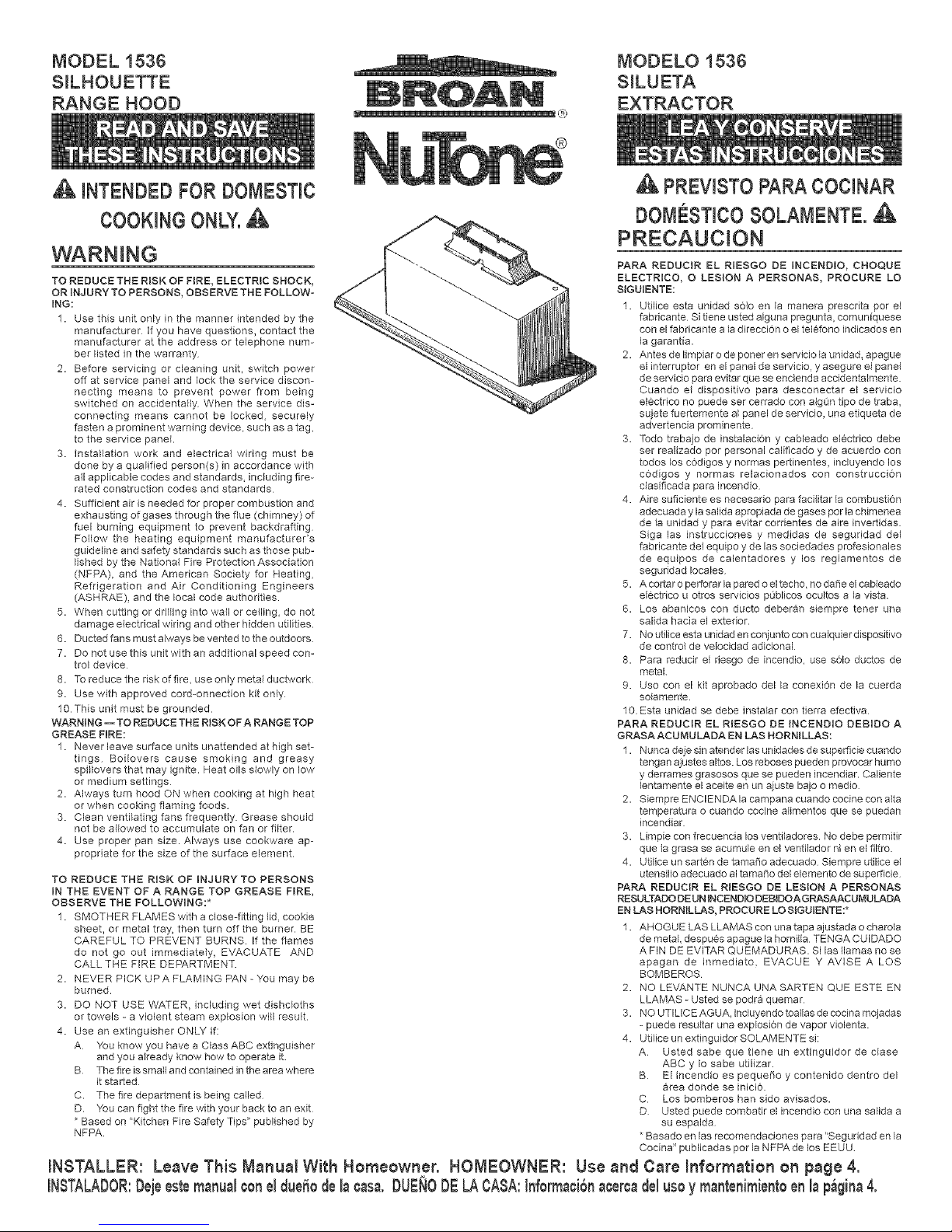
MODEL 1536
S_LHOUETTE
RANGE HOOD
A INTENDEDFORDOMESTIC
COOKINGONLY.A
L ®
MODELO 1536
S_LUETA
EXTRACTOR
WARNING
TO REDUCE THE RISK OF FIRE, ELECTRIC SHOCK,
OR INJURY TO PERSONS, OBSERVE THE FOLLOW-
ING:
1. Use this unit only in the manner intended by the
manufacturer If you have questions, contact the
manufacturer at the address or telephone num-
ber listed in the warranty
2. Before servicing or cleaning unit, switch power
off at service panel and lock the service discon-
necting means to prevent power from being
switched on accidentally When the service dis-
connecting means cannot be locked, securely
fasten a prominent warning device, such as a tag,
to the service panel.
3. Installation work and electrica{ wiring must be
done by a qualified person(s) in accordance with
all applicable codes and standards, including fire-
rated construction codes and standards
4. Sufficient air is needed for proper combustion and
exhausting of gases through the flue (chimney) of
fael burning equipment to prevent backdrafting
Follow the heating equipment manufacturers
guideline and safety standards such as those pub-
lished by the National Fire Protection Association
(NFPA), and the American Society for Heating,
Refrigeration and Air Conditioning Engineers
(ASHRAE)_ and the local code authodties.
5. When cutting or drilling into wall or ceiling, do not
damage electrical wiring and other hidden utilities.
6. Ducted fans must always be vented to the outdoors
7. Do not use this unit with an additional speed con-
trol device
8. To reduce the risk of fire, use only metal ductwork
9. Use with approved cord-onnection kit only
10 This unit must be grounded
WARNING-- TO REDUCE THE RISK OF A RANGE TOP
GREASE FIRE:
1. Never leave surface units unattended at high set-
tings Boflovers cause smoking and greasy
spil{overs that may ignite. Heat oils slowly on low
or medium settings
2. Always turn hood ON when cooking at high heat
or when cooking flaming foods
3. Clean ventilating fans frequently Grease should
not be allowed to accumulate on fan or filter.
4. Use proper pan size. Always use cookware ap-
propriate for the size of the surface element.
TO REDUCE THE RISK OF INJURY TO PERSONS
IN THE EVENT OF A RANGE TOP GREASE FIRE,
OBSERVE THE FOLLOWING:*
1. SMOTHER FLAMES with a close-fitting lid, cookie
sheet, or metal tray, then turn off the burner. BE
CAREFUL TO PREVENT BURNS If the flames
do not go out immediately, EVACUATE AND
CALL THE FIRE DEPARTMENT.
2. NEVER PICK UPA FLAMING PAN - You may be
burned.
3. DO NOT USE WATER, including wet dishcloths
or towels - a violent steam explosion will result.
4. Use an extinguisher ONLY if:
A You know you have a Class ABC extinguisher
and you already know how to operate it.
B The fire is smal_and contained in the area where
it started
C. The fire department is being called
D. You can fight the fire with your back to an exit
Based on "Kitchen Fire Safety Tips" published by
NFPA.
iNSTALLER: Leave This M_nu_l With Homeowner.
INSTALADOR:Dejeestemanu_lconeldueOodeI_¢_s_.DUEN0DELAOASA:Inforrna¢iGn_¢eroa
PREVISTOPAPACOCINAR
DOMESTmCOSOLAMENTE.
PRECAUCION
PARA REDUCIR EL RIESGO DE INCEND{O, CHOQUE
ELECTRICO, O LESION A PERSONAS, PROCURE LO
SIGUIENTE:
1. Utilice esta unidad solo en la manera prescdta por el
fabricante Si tiene usted alguna pregunta, comunfquese
con el fabricante a la direccion o el telCfono indicados en
la garantfa.
2. Antes de Iimpiar o de poner en servicio la anidad, apague
el interruptor en el panel de servicio, y asegure el panel
de servicio pare evitar que se encienda accidenta_mente.
Cuando el dispositivo para desconectar el servicio
el¢ctrico no puede ser cerrado con algon tipo de traba,
sujete fuertemente al panel de servicJo, una etiqueta de
advertencia prominente
3. Todo traba]o de instalaci0n y cableado el¢ctdco debe
ser realizado por personal calificado y de acuerdo con
todos los c0digos y normas pertinentes, incluyendo los
c0digos y normas relacionados con construccion
clasificada para incendio
4. Aire suficiente es necesario para facilitar la combustion
adecuada y la salida apropiada de gases por la chimenea
de la unidad y para evitar cordentes de aire invertidas.
Siga las instrucciones y medJdas de seguridad del
fabricante del equipo y de las sociedades profesionales
de equipos de calentadores y los reglamentos de
seguddad locales
5. A cortar o pertorar la pared o el techo, no da_e el cableado
ei¢ctrico u otros servicios pOblicos ocultos a la vista
6. Los abanicos con ducto deberan siempre tenet una
salida hacia el exterior.
7. No utilice esta unidad en conjunto con cualquier dispositivo
de control de velocidad adicional
8. Para reducir e{ desgo de incendio, use solo ductos de
metal
9. Uso con el kit aprobado della conexion de la cuerda
solamente.
10 Esta unidad se debe instalar con tierra efectNa
PARA REDUCIR EL RIESGO DE INCENDIO DEBIDO A
GRASA ACUMULADA EN LAS HORNILLAS:
1. Nunca deje sin atender las unidades de superfide cuando
tengan a]ustes altos. Los reboses pueden provocar humo
y derrames grasosos que se pueden incendiar. Caliente
lentamente el aceite en un ajuste bajo o medio
2. Siempre ENCIENDA la campana cuando cocine con alta
temperatura o cuando cocine alimentos que se puedan
incendiar
3. Limpie con frecuencia los ventiladores. No debe permitir
que la grasa se acumule en el ventilador ni en el filtro.
4. Utilice un sartcn de tamaOo adecuado Siempre utilice el
utensilio adecuado al tamaOo de{ elemento de superficie
PARA REDUCIR EL RIESGO DE LESION A PERSONAS
RESULTADO DEUN INCEND_ODEBJDOAGRASAACUMULADA
EN LAS HORNILLAS, PROCURE LO SIGUIENTE:*
1. AHOGUE LAS LLAMAS con una tapa ajustada o charola
de metal, despues apague la hornilia TENGA CUIDADO
AFIN DE EVITAR QUEMADURAS. Si las llamas no se
apagan de inmediato, EVACUE Y AVISE A LOS
BOMBEROS
2. NO LEVANTE NUNCA UNA SARTEN QUE ESTE EN
LLAMAS - Usted se podra quemar
3. NO UTILICE AGUA, induyendo toaIlas de cocina mojadas
- puede resultar una explosion de vapor violenta.
4. Utilice un extinguidor SOLAMENTE si:
A Usted sabe que tiene un extinguidor de clase
ABC y Io sabe utilizar.
B El incendio es pequeOo y contenido dentro del
area donde se inicio.
C Los bomberos han sido avisados.
D Usted puede combatir el incendio con una salida a
su espalda
Basado en las recomendaciones para "Seguridad en la
Cocina" publicadas por la NFPA de los EEUU
HON_=OWNER: Use _nd C_re Information on page 4.
del usoy mantenimientoen I_p_,gina4.
CAUTION
1. For general ventilating use only Do not use to exhaust
hazardous or explosive materials and vapors.
2 To avoid motor bearing damage and noisy and/
or unbalanced impellers, keep drywall spray,
construction dust, etc off power unit.
3 When using a thermostat with this product, fan may
start automatically. To reduce the risk of injury, switch
power off at service panM and {ock service panel to
prevent power from being switched on accidentally.
4 Your hood motor has a thermal overload which will
automatically shut off the motor if it becomes
overheated. The motor will restart when it cools
down. F the motor continues to shut off and restart,
have the hood serviced
5 Pease read specification label on product for fudher
information and requirements
PLAN THE INSTALLATION
Your new hood will fit a standard 36" wide flush bot-
tom or recessed bottom, framed or frameless kitchen
cabinet which has a minimum depth of 11" from face
to inside of back wall
The unit is ducted vertically. Horizontal ducting can
be accomplished as shown
For safe operation, the mounted hood must be a mini-
mum of 18" above the cooking surface
For easiest installation, range hood should be installed
in cabinet before mounting cabinet to wall.
NOTE 1
REMOVE GLASS DRAWER FROM UNiT BEFORE
INSTALMNG HOOD IN CABINET TO PROTECT
DRAWER FROM DAMAGE. SEE STEP 13 ON
PAGE 8.
This hood can easily be installed by following these
basic steps:
• Mark and cut out cabinet bottom
• Secure hood to cabinet
• Mount cabinet on wal{
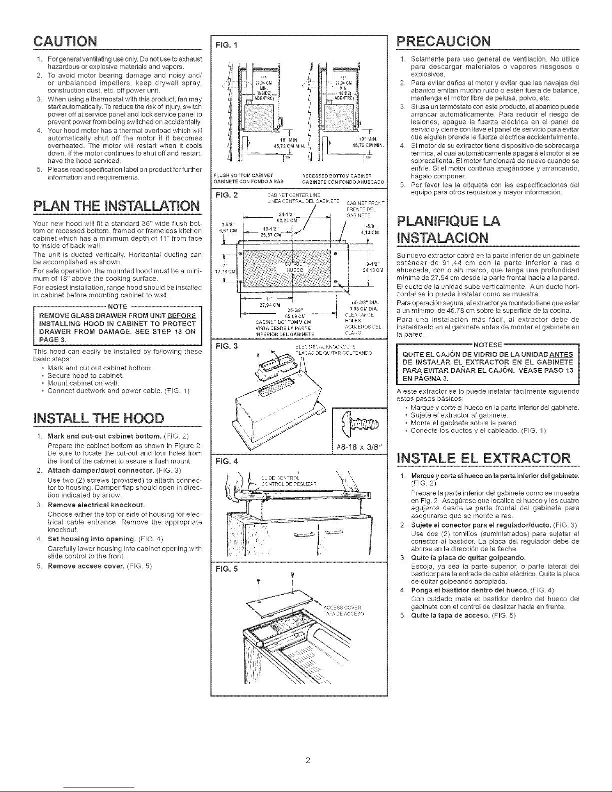
• Connect ductwork and power cable. (FiG 1)
INSTALL THE HOOD
1. Mark and cut=out cabinet bottom. (FIG. 2)
Prepare the cabinet bottom as shown in Figure 2.
Be sure to locate the cut-out and four holes from
the front of the cabinet to assure a flush mount.
2. Attach damper/duet connector. (FIG. 3)
Use two (2) screws (provided) to attach connec-
tor to housing. Damper flap should open in direc-
tion indicated by arrow
3. Remove electrical knockout.
Choose either the top or side of housing for elec-
trical cable entrance Remove the appropriate
knockout
4. Set housing into opening. (FIG. 4)
Carefully lower housing into cabinet opening with
slide control to the front
5. Remove access cover. (FIG. 5)
FiG. 1
FLUSH BOTTOM CABINET RECESSED BOTTOM CABINET
GABINETE CON FONDO A RAS GABiNETE CON FONDO AHUECADO
FiG. 2 CABINFT C ENTER LNE
2-5/8"
6,6? CM
65,09 CM
CABINET BOTTOM VIEW HOLES
VISTA DESDE LA PARTE A®UJEROS Dr/
INFERIOR DEL GABINETE CLARO
FiG. 3 ELECTRICALKNeCKOUTS
FiG. 4
#8 18 x 3/8'
FiG. 5
It
v I
PRECAUCION
1 Solamente para uso general de ventilaci6n No utilice
para descargar materiales o vapores riesgosos o
explosivos
2 Para evitar daSos al motor y evitar que las navaias del
abanico emitan mucho ruido o estcn fuera de balance,
mantenga el motor libre de pelusa, polvo, etc
3 Siusa un term6stato con este producto, el abanico puede
arrancar automaticamente. Para reducir el riesgo de
lesiones, apague la fuerza elcctrica en el panM de
servicio y cierre con ilave el panM de servicio para evitar
que alguien prenda la fuerza elcctrica accidentalmente.
4 Elmotor de su extractor tiene dispositivo de sobrecarga
t¢rmica, al cual automaticamente apagara el motor si se
sobrecalienta. El motor funcionara de nuevo cuando se
enfrie. Si el motor continua apagandose y arrancando,
hagalo componer.
5 Pot favor lea la etiqueta con las especificaciones del
equipo para otros requisitos y mayor informaci6n.
PLANIFtQUE LA
INSTALACION
Su nuevo extractor cabra en la parte inferior de un gabinete
estandar de 91,44 cm con la parte inferior a ras o
ahuecada, con o sin marco, que tenga una profundidad
minima de 27,94 cm desde la parte frontal hacia a la pared.
El ducto de la an{dad sube verticaimente A un ducto hori-
zontal se Io puede instalar como se muestra
Para operacion segura, el extractor ya montado tiene que estar
a un minimo de 45,78 cm sobre la superficie de la cocina.
Para una instalaci6n mas facil, a_ extractor debe de
instalarseM en el gabinete antes de montar el gabMete en
la pared
i NOTESE
QUITE EL CAJON DE VIDR{O DE LA UNIDAD ANTES
DE INSTALAR EL EXTRACTOR EN EL GABtNETE
PARA EVITAR DANAR EL CAJ6N. VEASE PASO 13
EN PAGINA 3,
A este extractor se Io puede instalar f&cilmente siguiendo
estos pasos basicos:
• Marque y corte el hueco en la parle inferior del gabinete
• Sujete el extractor al gabinete
• Monte el gabinete sobre la pared.
• Conecte los ductos y el cableado. (FIG. 1)
INS'TALE EL EXTRACTOR
1. Marque y corte M hueco en {a parte Mferior del gabMete.
(FIG. 2)
Prepare la parte inferior dM gabinete como se muestra
en Fig. 2 AsegOrese que Iocalice el hueco y los cuatro
agujeros desde la parte frontal dM gabMete para
asegurarse que se monte a ras
2 Sujeteelconectorparaelreguiadodducto.(FIG. 3)
Use dos (2) tornilbs (suministrados) para sujetar el
conector al bastidor. La placa dM regulador debe de
abrirse en la direccion de la flecha.
3 Quite la placa de quitar golpeando.
Escoja, ya sea la parte superior, o parte lateral del
bastidor para la entrada de cable el¢ctrico Quite la placa
de quitar gMpeando apropiada
4 Ponga el bastidor dentro del hueeo. (FIG 4)
Con cuidado meta el bastidor dentro dM hueco del
gabinete con el control de deslizar hacia en ffente.
5 Quite la tapa de acceso. (FIG 5)
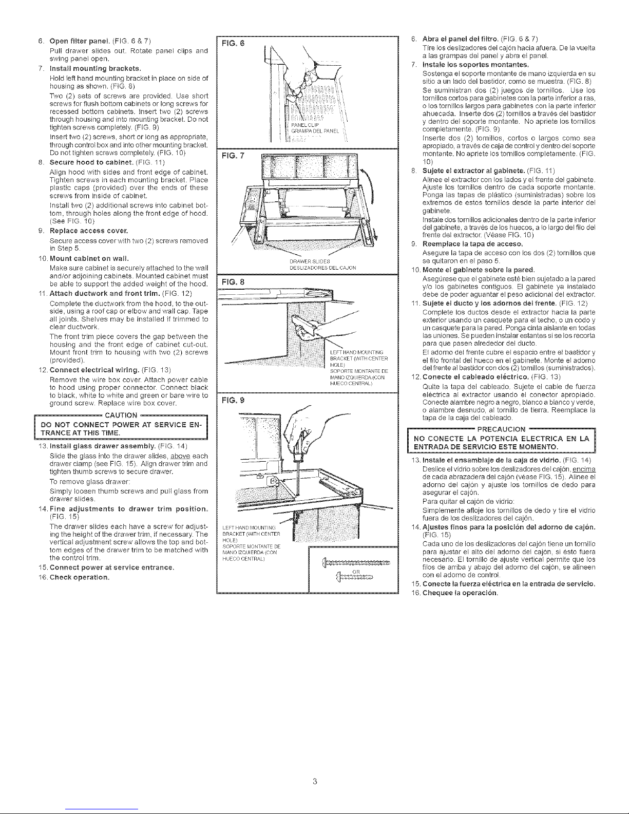
6.Openfilterpanel(FIG.6&7)
Pulldrawerslidesout.Rotatepanelclipsand
swingpanelopen
7.Install mounting brackets,
Hold left hand mounting bracket in place on side of
housing as shown• (FiG 8)
Two (2) sets of screws are provided Use short
screws for flush bottom cabinets or long screws for
recessed bottom cabinets insert two (2) screws
through housh_g and into mounting bracket• Do not
tighten screws completely. (FIG 9)
insert two (2) screws, short or long as appropriate,
through control box and into other mounting bracket•
Do not tighten screws completely (FIG. 10)
8. Secure hoodto cabinet, (FIG 11)
Align hood with sides and front edge of cabinet
Tighten screws in each mounting bracket• Place
plastic caps (provided) over the ends ef these
screws from inside of cabinet•
Mstall two (2) additional screws into cabinet bot-
tom, through holes along the front edge ef hood
(See FIG 10)
9. Replace access cover,
Secure access cover with twe (2) screws removed
in Step 5
10. Mount cabinet on wall,
Make sure cabinet is securely attached to the wall
and/or adjoinMg cabinets• Mounted cabinet must
be able to support the added weight ef the hood
11 Attach ductwork and front trim. (FIG 12)
Complete the ductwork from the hood, to the out-
side, using a roof cap or elbow and wall cap Tape
all joints• Shelves may be installed if trimmed to
clear dactwork.
The front trim piece covers the gap between the
housMg and the front edge of cabinet cut-out.
Mount front trim to housing with two (2) screws
(provided)
12. Connect electrical wiring. (FIG. 13)
Remove the wire box cover Attach power cable
to hood usMg proper connecter Connect black
to black, white to white and green or bare wire to
ground screw Replace wire box cover•
= CAUTION 1
DO NOT CONNECT POWER AT SERVICE EN-
TRANCE AT THiS TIME.
13. Install glass drawer assembly, (FIG 14)
S_ide the glass h_te the drawer slides, above each
draw'er clamp (see FIG 15)• Align drawer trim and
tighten thumb screws te secure drawer.
To remove glass drawer:
Simply loosen thumb screws and pull glass from
drawer slides.
14. Fine adjustments to drawer trim position.
(FIG. 15)
The drawer slides each have a screw for adjust-
ing the height of the drawer trim, if necessary The
vertical adjustment screw allows the top and bot-
tom edges of the drawer trim to be matched with
the control trim
15. Connect power at service entrance.
16. Check operation.
FiG. 6
FiG. 8
FiG. 9
LEFT HAND MOUNTING
BRACKET (WITH CF NTER
HOLE}
SOPORTE MONTANT _ DE
MANO iZQI;IFRDA ((ON
HUECO CENTRAL)
F'ANELCLIP
GRAMF'A DEL PANEL
DRAWER SLIDES
DESLIZADORES DEL CAJON
SOPORTE MONTANT c DE
MANO IZQI JlFRDA (CON
HUECO CENTRAL)
6 Abra el panel del filtro, (FIG 6 & 7)
Tire les deslizadores del cajon hacia afuera De la vuelta
alas grampas del panel y abra el panel
7 Inetale los soportes montantee,
Sostenga el soporte montante de mano izquierda en su
sitie a un lado del bastidor, como se muestra. (FIG. 8)
Se suministran dos (2) juegos de tornillos. Use los
tornillos cortos para gabinetes con la parte inferior a ras,
o {os tornillos largos para gabinetes con la parte inferior
ahuecada. Inserts dos (2) tornillos a travcs del bastidor
y dentro dM soporte montante. No apdete los tornillos
cempletamente. (FIG 9)
Inserte dos (2) tornillos, cortos o largos como sea
apropiado, a travcs de caja de control y dentro del seporte
montante No apdete los torniHos completamente (FIG.
10)
8 Sujete el extractor al gabinete, (FIG. 11)
AIinee el extractor con los lados y M ffente del gabinete
Ajaste los tornillos dentro de cada seporte montante.
Ponga las tapas de plastico (suministradas) sobre los
extremes de estos tornillos desde la parte interior dM
gabinete.
Instale des ternilles adicienales dentro de la parte inferior
del gabinete, a travcs de los huecos, a Io _argodel filo del
frente del extractor• (Vcase FIG. 10)
9 Reemplace la tapa de aceeeo.
Asegure la tapa de acceso con los dos (2) tornillos que
se quitaron en el paso 5.
10 Monte el gabinete eobre la pared,
Asegumse que el gabinete est¢ bien sujetado a la pared
y/o los gabh_etes contiguos El gabinete ya instalado
debe de poder aguantar el peso adicional del extractor•
11. Sujete el ducto y lee adomoe del frente. (FIG 12)
Complete los ductos desde el extractor hacia la parte
exterior usando un casquete para el techo, o an codo y
un casquete para la pared• Ponga cinta aislante en todas
las uniones. Se pueden instalar estantes si se los recerta
para que pasen alrededor del ducto
El adomo del frente cubre M espacio entre el bastidor y
el file frontal del hueco en el gabinete Monte el adorno
del frente al bastidor con dos (2) tornillos (suministrades).
12 Conecte el cableado el_ctrieo. (FIG. 13)
Quite la tapa del cableado Sujete el cable de fuerza
el¢ctrica al extractor usando el conector apropiado.
Conecte alambre negro a negro, blanco a blanco y verde,
e a{ambre desnudo, al ternillo de tierra. Reemplace la
tapa de la caja dM cableado
i PRECAUC{ON I
NO CONECTE LA POTENCIA ELECTRICA EN LA
ENTRADA DE SERV_ClO ESTE MOMENTO.
13 Instals el eneamblaje de la caja de viddo. (FIG 14)
DesHce el vidrio sobre los deslizadores del cajon, encima
de cada abrazadera del cajon (vcase FIG. 15). Alines M
adomo del caj6n y ajuste los tornillos de dedo para
asegurar el cajon.
Para quitar el caj6n de vidrio:
Simplemente afleje los ternillos de dede y tire el viddo
fuera de los deslizaderes del caj6n.
14 Ajustes fines para la poeici6n del adorno de ¢aj6n.
(FIG 15)
Cada uno de los deslizadores dM caj6n tiene un tornillo
para ajustar el alto dM adorno dM cajon, si Csto fuera
necesado El tornillo de ajuste vertical permits que los
fHos de ardba y abajo del adorno del cajon, se alineen
con el ademo de control
15 Conecte la fuerza el_ctdea en la entrada de eervicio.
16 Chequee la operaci6n.
 Loading...