

Broan NuTone 1530 Installation Manual
MODEL 1530
SmLHOUETTE
RANGE HOOD
iNTENDEDFOR
DOMESTICCOOKINGONLY.A
MODELO 1530
S_LUETA
EXTRACTOR
WARNING
TO REDUCE THE RISK OF FIRE, ELECTRIC SHOCK,
OR iNJURY TO PERSONS, OBSERVE THE FOLLOW°
{NG:
1 Use this unit only in the manner intended by the
manufacturer. Ifyou have questions, contact the
manufacturer at the address or telephone num-
ber listed in the warranty.
2 Before servicing or cleaning unit, switch power
off at service panel and lock the service discon-
necting means to prevent power from being
switched on accidentally. When the service dis-
connecting means cannot be locked, securely
fasten a prominent warning device, such as a tag,
to the service panel
3 Installation work and electrical wiring must be
done by a qualifed person(s) in accordance with
all applicable codes and standards, including fire-
rated construction codes and standards.
4 Sufficient air is needed for proper combustion and
exhausting of gases through the flue (chimney) of
fuel burning equipment to prevent backdrafiing.
Follow the heating equipment manufacturer's
guideline and safety standards such as those pub-
lished by the National Fire Protection Association
(NFPA), and the American Society for Heating, Re-
frigeration and Air Conditioning Engineers
(ASHRAE), and the local code authorities
5 When catting or drilling into wall or ceiling, do not
damage electrica_ wiring and other hidden utilities
6 Do not use this range hood with an additional
speed control device.
7 Ducted fans must always be vented to the out-
doors
8 To reduce the risk of fire, use only metal ductwork
9 Use with approved cord-connection kit only.
10. This unit must be grounded
TO REDUCE THE RISK OF A RANGE TOP GREASE
FIRE:
1 Never leave surface units unattended at high set-
tings. Boilovers cause smoking and greasy
spillovers that may ignite Heat oils slowly on low
or medium settings.
2 Always turn hood ON when cooking at high heat
or when cooking flaming foods.
3 Clean ventilating fans frequently. Grease should
not be allowed to accumulate on fan or liter
4 Use proper pan size A_ways use cookware ap-
propriate for the size of the surface element
TO REDUCE THE RISK OF INJURY TO PERSONS
{N THE EVENT OF A RANGE TOP GREASE FIRE,
OBSERVE THE FOLLOWING:*
1 SMOTHER FLAMES with a close-ftting lid, cookie
sheet, or metal tray, then turn off the burner BE
CAREFUL TO PREVENT BURNS If the flames
do not go out immediately, EVACUATE AND CALL
THE FIRE DEPARTMENT
2 NEVER PICK UP A FLAMING PAN - You may be
burned
3 DO NOT USE VVATER, including wet dishcloths
or towels - a violent steam explosion will result
4 Use an extinguisher ONLY if:
A. You know you have a Class ABC extinguisher
and you already know how to operate it
B The fire issmall and contained in the area where
it started.
C The fire department is being called.
D You can fght the fire with your back to an exit
Based on "Kitchen Fire Safety Tips' published by
NFPA
MODEL 1530
SILHOUETTE RANGE HOOD
MODELO 1530
SILUETA EXTRACTOR
iNSTALLER: Leave This Manuam With
Homeowner. HOMEOWNER: Use
and Care information on page 4.
INSTALADOR:Dejeestemanual¢0n el dueh0
delacasa. DUEN0 DE LA CASA:
Informa¢iOnaoer¢_del uso y mantenimiento
en I_p_gin_4.
PREVISTOPARACOCINAR
DOMESTICOSOLAMENTE
PRECAUC ON
PARA REDUCIR EL RIESGO DE INCENDIO, CHOQUE
ELECTRICO, O LESION A PERSONAS, PROCURE LO
SIGUIENTE:
1 Utilice esta unidad sOlo en la manera prescdta per el
fabdcante. Si tiene usted alguna pregunta, comuniqaese
con el fabdcante a la direccion o el telcfono indicados en
la garantia.
2 Antes de limpiar o de poner en servicio la unidad, apague
el interruptor en el panel de servicio, y asegure el panel
de servicio para evitar que se encienda accidentalmente.
Cuando el dispositivo para desconectar el servicio
el¢ctrico no puede ser cerrado con alg0n tipo de traba,
sujete fuertemente al panel de servicio, una etiqueta de
advertencia prominente.
3 Todo trabajo de instalaciOn y cableado el¢ctrico debe
set realizado pot personal calificado y de acuerdo con
todos los codigos y normas pertinentes, incluyendo los
cOdigos y normas relacionados con construccion
clasificada para incendio
4 Aire suficiente es necesario para facilitar la combustion
adecuada y la salida apropiada de gases pot la chimenea
de la unidad y para evitar corrientes de aire invertidas
Siga las instrucciones y medidas de seguridad del
fabricante del equipo y de las sociedades profesionales
de equipos de calentadores y los reglamentos de
seguridad locales
5 A cortar o perforar la pared o eltecho, no da5e el cableado
el¢ctrico u otros servicios pQblicos ocultos a la vista
6 No utilice este ventilador con ningun dispositivo de
una control de velocidad de estado solido adicional
7 Los abanicos con ducto deberan siempre tener una
salida hacia el exterior
8 Para reducir el riesgo de incendio, use solo ductos de
metal.
9 Uso con el kit aprobado della conexion de la cuerda
solamente.
10. Esta unidad se debe insta}ar con tierra efectiva
PARA REDUCIR EL RIESGO DE INCENDIO DEBIDO A
GRASA ACUMULADA EN LAB HORN_LLAB:
1 Nunca deje sin atender las unidades de superficie
cuando tengan ajustes altos. Los reboses pueden
provocar humo y derrames grasosos que se pueden
incendiar Caliente lentamente el aceite en un ajuste
bajo o medio.
2 Siempre ENCIENDA la campana cuando cocine con
alta temperatura o cuando cocine alimentos que se
puedan incendiar.
3 Limpie con frecuencia los ventfladores. No debe permitir
que la grasa se acumule en el ventilador ni en el ffltro.
4 Utilice un sart¢n de tamafio adecuado. Siempre utilice
el utensilio adecuado al tamaeio del efemento de
superficie
PARA REDUCIR EL RIESGO DE LESION A PERSONAS
RESULTADO DE UNINCENDtO DEBIDOAGRASAACUMULADA
EN LAB HORNILLAS, PROCURE LO SiGUIENTE:*
1 AHOGUE LAB LLAMAS con una tapa ajustada o charola
de metal, despu¢s apague la hornilla. TENGA CUIDADO
A FIN DE EVITAR QUEMADURAS Si las llamas no se
apagan de inmediato, EVACUE Y ARISE A LOS
BOMBEROS.
2 NO LEVANTE NUNCA UNA SARTEN QUE ESTE EN
LLAMAS - Usted se podra quemar
3 NO UTIUCE AGUA, incluyendo toallas decocina moiadas
- puede resultar una explosiOn de vapor violenta.
4 Utilice un extinguidor SOLAMENTE si:
A. Usted sabe qua tiene an extinguidor de clase
ABC y Io sabe utilizar
B. El incendio es peqaeeio y contenido dentro del
area donde se inici6
C. Los bomberos han sido avisados
D Usted puede combatir el incendio con una salida a
su espalda.
Basado en las recomendaciones para ' Seguddad en la
Cocina" publicadas pot la NFPA de los EEUU.
CAUTION
1 Forgeneral ventilating use only. Do not use to exhaust
hazardous or explosive materials and vapors.
2 To avoid motor bearing damage and noisy and/
or unbalanced impellers, keep drywall spray,
construction dust, etc off power unit.
3 When using a thermostat with this product, fan may
start automatically. To reduce the risk of injury, switch
power off at service panel and lock service panel to
prevent power from being switched on accidentally
4 Your hood motor has a thermal overload which will
automatically shut off the motor if it becomes
overheated. The motor will restart when it cools
down. If the motor continues to shut off and restart,
have the hood serviced
5 P_ease read specification label on product for further
information and requirements.
PLAN THE INSTALLATION
Your new hood will fit a standard 30" wide flush bot-
tom or recessed bottom, framed or frameless kitchen
cabinet which has a minimum depth of 11" from face
to inside of back wall.
The unit is ducted vertically Horizontal ducting can
be accomplished as shown.
For safe operation, the mounted hood must be a mini-
mum of 18" above the cooking surface.
For easiest installation, range hood should be installed
in cabinet before mounting cabinet to wall.
NOTE --
REMOVE GLASS DRAWER FROM UNiT BEFORE
INSTALLING HOOD IN CABINET TO PROTECT
DRAWER FROM DAMAGE. SEE STEP 13 ON
PAGE 3.
This hood can easily be installed by following these
basic steps:
• Mark and cut out cabinet bottom
• Secure hood to cabinet
• Mount cabinet on wail
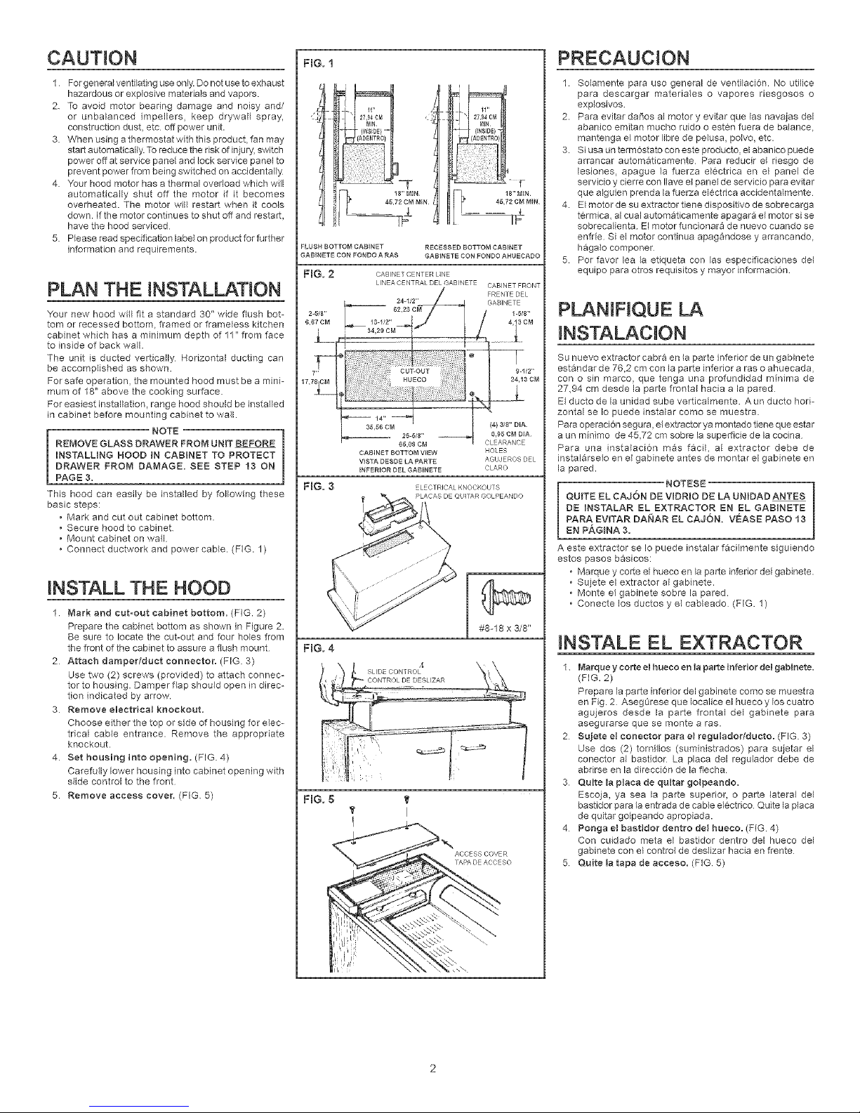
• Connect ductwork and power cable. (FIG. 1)
INSTALL THE HOOD
1 Mark and cut-out cabinet bottom. (FIG. 2)
Prepare the cabinet bottom as shown in Figure 2.
Be sure to locate the cut-out and four holes from
the front of the cabinet to assure a flush mount
2 Attach damper/duet connector. (FIG. 3)
Use two (2) screws (provided) to attach connec-
tor to housing. Damper flap should open in direc-
tion indicated by arrow.
3 Remove eJectNcaJ knockout.
Choose either the top or side of housing for elec-
trical cable entrance. Remove the appropriate
knockout.
4 Set housing into opening. (FIG 4)
Carefully lower housing into cabinet opening with
slide control to the front
5 Remove access cover. (FIG 5)
FIG. 1
FLUSH BOTTOM CABINET
GABiNETE CON FONDO A RAS
FIG. 2 CABNETCENTERlINE
RECESSED BOTTOM CAB}NET
GABINETE CON FONDO AHUEC&DO
FIG. 3
FIG. 4
65,09 CM
CABINET BOTTOM V}EW HOLES
VISTA DESDE LA PARTE AGUJEReS DEL
INFERIOR DEL GABJNETE CLARe
_LCCTRICAL KNOCKOUTS
#8-18 x 3/8"
PRECAUCJON
1. So_amente para uso general de ventilaci6n. No utilice
para descargar materiales o vapores riesgosos o
explosivos
2. Para evitar daSos al motor y evitar que las navajas del
abanico emitan mucho ruido o eaten fuera de balance,
mantenga el motor libre de pelusa, po_vo, etc.
3. Si usa un term6stato con este producto, el abanico puede
arrancar automaticamente Para reducir el riesgo de
lesiones, apague la fuerza el¢ctdca en el panel de
servicio y cierre con Ilave e{ panel de servicio para evitar
que alguien prenda la fuerza el¢ctrica accidentaimente
4. El motor de su extractor tiene dispositivo de sobrecarga
tcrmica, al cual automaticamente apagara el motor si se
sobrecalienta El motor funcionara de nuevo cuando se
enfrte Si el motor continua apagandose y arrancando,
hagalo componer
5. Pot favor lea la etiqueta con las especificaciones del
equipo para otros requisitos y mayor informacion
PLANJHQUE LA
INSTALACJON
Su nuevo extractor cabra en la parte inferior de un gabinete
estandar de 76,2 cm con la parte inferior a ras o ahuecada,
con o sin marco, que tenga una profundidad minima de
27,94 cm desde la parte frontal hacia a la pared
E_ducto de la unidad sube verticalmente. Aun ducto hori-
zontal se Io puede instalar como se muestra.
Para operaci6n segura, el extractor ya montado tiene que estar
a un minimo de 45,72 cm sobre la superticie de la cocina
Para una instalaci6n mas facil, al extractor debe de
instalarselo en e{ gabinete antes de montar el gabinete en
la pared.
NOTESE
QUITE EL CAJON DE VIDRIO DE LA UNIDAD ANTES
DE INSTALAR EL EXTRACTOR EN EL GABINETE
PARA EWTAR DANAR EL CAJON. VEASE PASO 13
EN PAGINA 3.
A este extractor se Io puede instalar facilmente siguiendo
estos pasos basicos:
• Marque y corte el hueco en la parte inferior del gabJnete.
• Sujete el extractor al gabinete.
• Monte el gabinete sobre la pared.
• Conecte los ductos y el cableado (FIG. 1)
INSTALE EL EXTRACTOR
1 Marqueycorteelhuecoenlaparteinferiordelgabinete.
(FIG. 2)
Prepare la parte inferior del gabinete come se muestra
en Fig. 2 Aseg0rese que Iocalice el hueco y los cuatro
agujeros desde la parte frontal del gabinete para
asegurarse que se monte a ras.
2 Sujete el conector para el reguladorlducto. (FIG. 3)
Use dos (2) tornillos (suministrados) para sujetar el
conector al bastidor La placa del regulador debe de
abdrse en la direcci6n de la flecha
3 Quite JapJaca de quJtar goJpeando.
Escoja, ya sea la parte superior, o parte lateral del
bastidor para la entrada de cable ei¢ctrico Quite la placa
de quitar go_peando apropiada.
4 Ponga el bastidor dentro deJhueco. (FIG. 4)
Con cuidado meta el bastidor dentro del hueco del
gabinete con el control de deslizar hacia en frente
5 Quite latapa de acceso. (FIG 5)

6.Openfilterpanel.(FIG6&7)
PulldrawerslidesoutRotatepanelclipsand
swingpanelopen
7.Installmountingbrackets.
Msertbentendofinstallationrodintoaccesshole
inhousing(FIG.8)
Choosethemountingbracketwiththecenterhole•
Hangthebracketfromtherod,throughthiscen-
terhole,asshownPullbracketupbetweencabi-
netandhousing.(FIG9)
HoldmountingbracketinplacewithrodTwosets
ofscrewsareprovidedUseshortscrewsforflush
bottomcabinetsorlongscrewsforrecessedbot-
tomcabinetsInserttwo(2)screwsthroughhous-
ingandintomountingbracketDonottighten
screwscompletely(FIG.10)
Mserttwo(2)screws,shortorlongasappropbate,
throughcontrolboxandintoothermountingbracket
Donottightenscrewscompletely•(FIG11)
8.Securehoodtocabinet.(FIG.12)
Alignhoodwithsidesandfrontedgeofcabinet.
Tightenscrewsineach mounting bracket• Place
plastic caps (provided) over the ends of these
screws from inside of cabinet
install two (2) additional screws into cabinet bot-
tom, through holes along the front edge of hood
(See FIG 11)
9. Replace access cover.
Secure access cover with two (2) screws removed
in Step 5.
10 Mount cabinet on wall
Make sure cabinet is securely attached to the wall
and/or adjoining cabinets Mounted cabinet must
be able to support the added weight of the hood
11. Attach ductwork and front trim. (FIG 13)
Complete the ductwork from the hood, to the out-
side, using a roof cap or elbow and wall cap Tape
air joints Shelves may be installed if trimmed to
clear ductwork
The front trim piece covers the gap between the
housing and the front edge of cabinet cut-out
Mount front trim to housing with two (2) screws
(provided)•
12 Connect electrical wiring. (FIG. 14)
Remove the wire box cover• Attach power cable
to hood using proper connector• Connect black
to black, white to white and green or bare wire to
ground screw• Replace wire box cover
CAUTION I
DO NOT CONNECT POWER AT SERVICE EN-
TRANCE AT THIS T_ME=
13 Install glass drawer assembly. (H G. 15)
Slide the glass into the drawer slides, above each
drawer clamp (see FIG. 16). Align drawer trim and
tighten thumb screws to secure drawer
To remove glass drawer:
Simply loosen thumb screws and pull glass from
drawer s_ides.
14 Fine adjustments to drawer trim position.
(FiG 16)
The drawer slides each have a screw for adjust-
ing the height of the drawer trim, if necessary• The
vertical adjustment screw allows the top and bot-
tom edges of the drawer trim to be matched with
the control trim
15 Connect power at service entrance.
16 Check operation.
FIG. 5
FIG. 7
PANFLCL P
GRAMPA DEL PANEL
i_i ¸ • ii
DRAWER SLIDFS
DFSL ZADORES DE/CAJON
FIG. 8
i
INSTALLATION ROD
VARILLA DE INSTALACION
i!
y
ACCESS HOLE
HHECO DE ACCESO
FIG. 9
FIG. 10
TORNI//OS AQ ]1
6 Abra el panel del filtro. (FIG. 6 & 7)
Tire los deslizadores del caj6n hacia afuera. De la vuelta
alas grampas del panel y abra el panel
7 Instals los soportes para montar.
Inserte la parte doblada de la varilla de instalaci6n dentro
del hueco de acceso en el bastidon (FIG 8)
Escoja el soporte montante con el hueco central
Cuelgue el soporte de la varilla a travCs de este hueco
central como se muestra. Tire el soporte hacia arriba
entre el gabinete y el bastidor (FIG. 9)
Sostenga el soporte montante en su sitio con la varilla
Se han suministrado dos juegos de tornillos Use los
tornillos cortos para gabinetes con el parts inferior a ras,
o tomillos largos para gabinetes con la parte inferior
ahuecada Inserts dos (2) tornillos a travcs del bastidor
y dentro del soporte montante No ajuste los torniHos
completamente (FIG 10)
Inserts dos (2) tomillos, cortos o largos como sea
apropiado, a travcs de Is caja de control y dentro del
otro soporte montante No ajuste los tornillos
completamente. (FIG. 11)
8 Sujete el extractor al gabinete. (FIG 12)
Alines el extractor con los lados y el frente del gabinete.
Ajuste los tornillos dentro de cada soporte montante
Ponga las tapas de plastico (suministradas) sobre los
extremos de estos tornillos desde la parte interior del
gabinete
Instale dos tornillos adicionales dentro de la parte inferior
del gabinete, a travcs de los huecos, a _olargo del filo del
frente del extractor. (VCase FIG. 11 )
9 Reempiace la tapa de acceso.
Asegure Is tapa de acceso con los dos (2) tornillos que
se quitaron en el paso 5.
10. Monte el gabinete sobre la pared.
Aseg0rese que e[ gabinete est¢ bien sujetado a la pared
y/o los gabinetes contiguos El gabinete ya instalado
debe de poder aguantar el peso adicional del extractor•
11 Sujete el ducto y los adornos del frente. (FIG. 13)
Complete los ductos desde el extractor hacia la pare
extedor usando un casquete para el techo, o un codo y
un casquete para la pared Ponga cinta aislante en todas
las uniones. Se pueden instalar estantes si se los recorta
para que pasen alrededor del ducto
El adorno del frente cubre el espacio entre el bastidor y
el fi_ofrontal del hueco en el gabinete. Monte el adomo
del frente al bastidor con dos (2) torniltos (suministrados).
12. Conecte el ¢ableado el_ctrico, (FIG. 14)
Quite la tapa del cableado. Sujete el cable de fuerza
el¢ctrica al extractor usando el conector apropiado
Conecte alambre negro a negro, blanco a blanco y verde,
o alambre desnudo, al tornillo de tierra Reemplace la
tapa de la caja del cableado
l PRECAUCION ]
NO CONECTE LA POTENCIA ELECTRICA EN LA
ENTRADA DE SERVICIO ESTE MOMENTO.
13. Instaie el ensamblaje de la caja de vidrio. (FIG. 15)
Deslice el viddo sobre los deslizadores del caj6n encima
de cada abrazadera det caj6n (vcase FIG 16) Alinee el
adomo del cajon y ajuste los tornitlos de dedo para
asegurar el cajon
Para quitar el caj6n de vidrio:
Simplemente afloje los tornillos de dedo y tire el vidrio
fuera de los deslizadores dei caj6n
14. Ajustes finos para la posici6n del adorno de caj6n.
(FIG. 16)
Cada uno de los deslizadores del cajon tiene un tornillo
para ajustar el alto del adorno del caj6n, si Csto fuera
necesado. El tornHIo de ajuste vertical permite que los
filos de arriba y abajo del adorno del caj6n, se alineen
con el adorno de control
15. Conecte la fueraa el_ctrica en la entrada de servicio.
16. Cheques la operaci6n.
 Loading...