

Broan EPLEC1, NPLEC1 Installation Use And Care Manual
WWW.BROAN.COM WWW.BROAN.CA WWW.NUTONE.CA
DE CUISINIÈRE
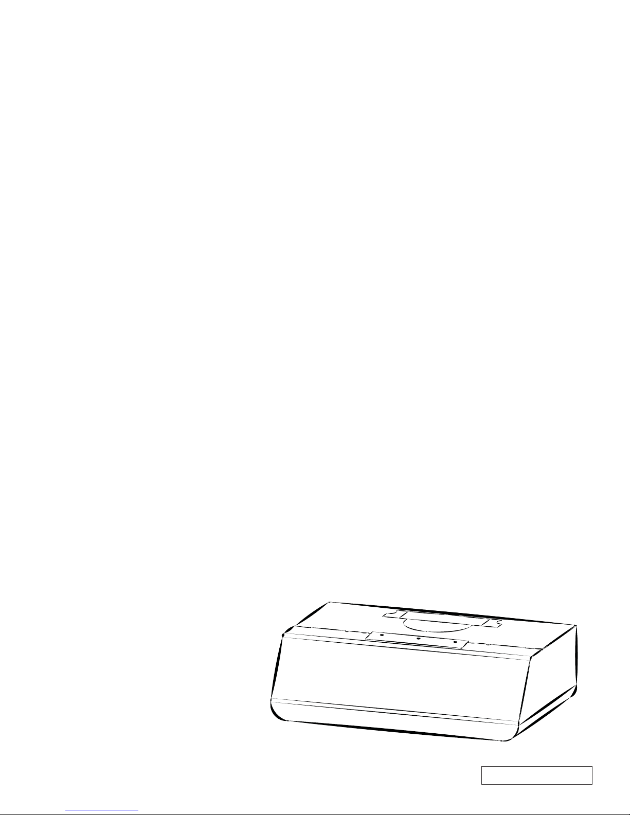
RANGE HOOD
Series: EPLEC1 and NPLEC1
INSTALLATION, USE
AND CARE MANUAL
English - See page 2
HOTTE
Séries : EPLEC1 et NPLEC1
MANUEL D’INSTALLATION,
D’UTILISATION ET D’ENTRETIEN
Français - Voir en page 27
CAMPANA
DE COCINA
Series: EPLEC1 y NPLEC1
MANUAL DE INSTALACIÓN,
USO Y CUIDADO
Español - Vease la pagína 60
Serial number:
99045656-003A
For ADA compliance installation guidelines, please visit www.broan-nutone.com
Recommended Tools and Accessories
for Installation
• Measuring tape
• Phillips screwdriver no. 2
• Nut driver or socket 11/32”
• Flat blade screwdriver (to open knockout holes)
• Drill, 1/8” drill bit and 1½” hole saw (to mark holes for ducting and cut electrical access hole)
• 7/64” drill bit (to drill holes for EZ1 brackets mounting screws)
• Wood shims (2) and wood screws (4) (required for standard installation to framed cabinet)
• Saw (to cut holes for ducted application)
• Sheet metal shears (ducted installation only, for duct adjustment)
• Pliers (ducted installation only, for duct adjustment)
• Metal foil duct tape (for ducted applications)
• Scissors (to cut metal foil duct tape)
• Pencil
• Wire stripper
• Strain relief, 1/2” diameter (to secure house wiring cable to the hood)
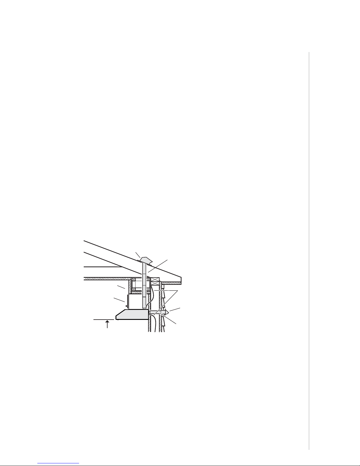
Install Ductwork (Ducted Installations Only)
ROOF CAP
3¼" X 10", 3¼" X 14" OR
7" ROUND DUCT
(FOR VERTICAL
DISCHARGE
SOFFIT
CABINET
HOOD
18" MIN - 24" MAX
COOKING SURFACE
ABOVE
NOTE: Distances over 24” are at the installer and user discretion.
1 ] Determine whether hood will discharge vertically (3¼” x 10”, 3¼” x 14” or 7” round),
or horizontally (3¼” x 10” or 3¼” x 14” only).
2 ] Decide where the ductwork will run between the hood and the outdoors.
3 ] Choose a straight, short duct run to allow the hood to perform most efficiently. Long duct
runs, elbows and transitions will reduce the performance of the hood. Use as few of them as
possible. When possible, use at least 2 foot straight runs before any turns. Larger ductwork
may be required for best performance with longer duct runs.
4 ] Install wall cap or roof cap (sold separately); ensure there is no leak in house insulation.
Connect metal ductwork to cap and work back towards the hood location. Use 2” metal foil
duct tape to seal the joints between ductwork sections.
HOUSE WIRING
(TOP OR BACK OF HOOD)
WALL CAP
3¼" X 10" OR
3¼" X 14" DUCT
(FOR HORIZONTAL DISCHARGE)
)
INSTALLATION
INSTALLATION MANUAL
7
Contents
VERTICAL EXHAUST
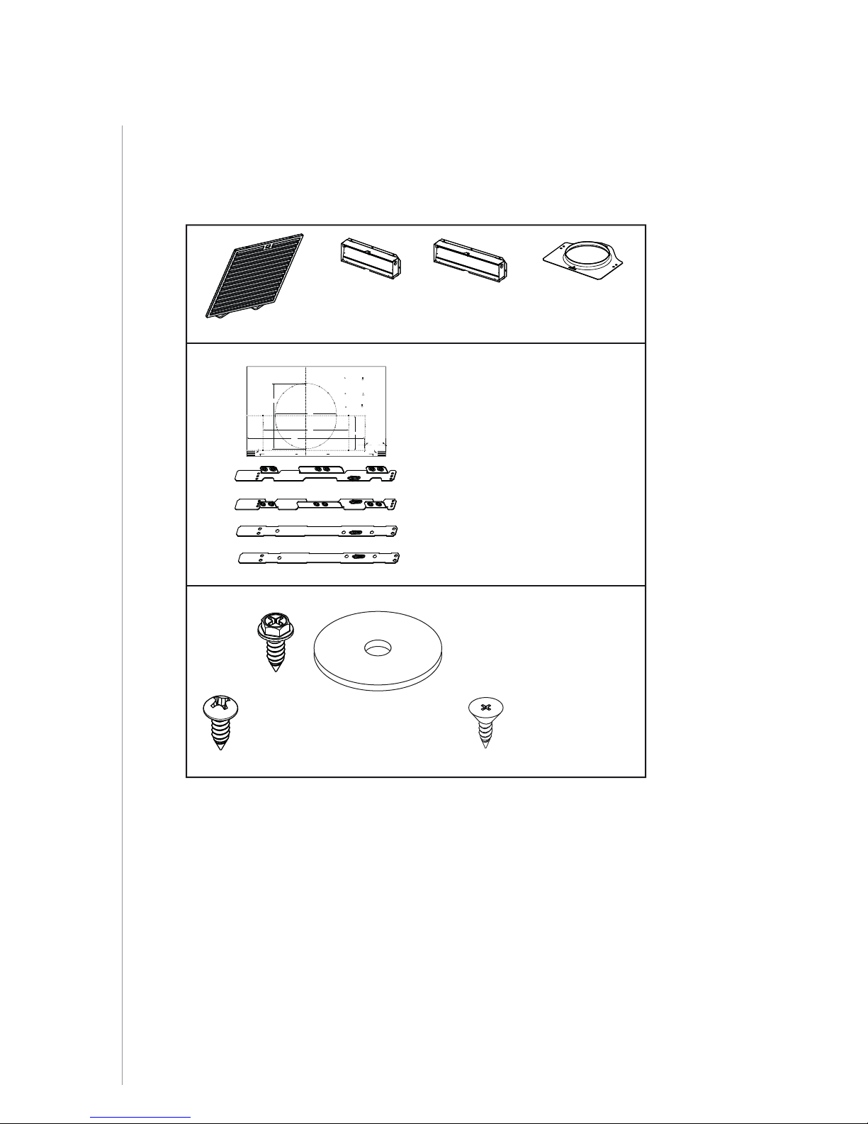
Before proceeding to the installation, check the contents of the box. If items are missing or
damaged, contact the manufacturer.
Make sure that the following items are included:
(2) GREASE FILTERS
Use this template for marking; do not attempt to cut out the ducting hole through it.
NOTE: These cutouts are clearance holes; they do not need to be the exact size of ducting.
Utiliser ce gabarit pour marquer vos repères; ne pas tenter de découper
le trou pour le conduit à travers le gabarit.
NOTE : Les découpes incluent le jeu nécessaire à l’installation; elles ne doivent pas
être du format exact des conduits.
Use esta plantilla para crear marcados; no trate de cortar el
agujero del conducto a través de la plantilla.
NOTA: To be translated in Spanish.
Bend template along graduated
scale when installing to framed
cabinet.
C
Pour une installation sous une
armoire à fond en retrait, utiliser les
lignes pour mesurer l’épaisseur du
décalage causé par le mur de
l’armoire et plier le gabarit en
8”
conséquence.
To be translated in Spanish.
C
(1) 3¼” X 10”
D
AMPER ASSEMBLY*
(1) 3¼” X 14”
D
AMPER ASSEMBLY*
* FIND INSIDE OF HOOD
OMPONENTS
EZ1 C
MARK WHERE INDICATED
FOR THE APPROPRIATE SIZE DUCT OPENING
RECTANGULAR DUCTING7” ROUND DUCTING
OR
= 3¼” x 10”
= 3¼” x 14”
MARQUER LES REPÈRES AUX ENDROITS INDIQUÉS SELON
LE FORMAT DE CONDUIT UTILISÉ
CONDUIT RECTANGULAIRECONDUIT ROND DE 7 PO
OU
= 3¼ po x 10 po
= 3¼ po x 14 po
TITLE TO BE TRANSLATED IN SPANISH
CONDUCTO RECTANGULARCONDUCTO REDONDO
O
= 3¼ pulg. x 10 pulg.
DE
7 PULG.
C
14½”
Appuyer ce bord au mur arrière
L
7½”
10½”
= 3¼ pulg. x 14 pulg.
Electrical access hole center
A = single blower hood
B = double blower hood
Centre du trou pour fil
d’alimentation électrique
A = hotte ventilateur simple
B = hotte ventilateur double
To be translated in Spanish
Electrical access hole center
4¼”
A = single blower hood
B = double blower hood
AB
Apoyar este borde contra la pared de atrásPlace this edge against back wall
C
(1) TEMPLATE FOR DUCTING
(PRINTED BOTH SIDES)
(2) INSTALLATION BRACKETS**
FOR FRAMED CABINET
(2) INSTALLATION BRACKETS**
FOR FRAMELESS CABINET
** FIND EZ1 BRACKETS ATTACHED INSIDE OF HOOD
ARTS BAG*** CONTAINING:
(1) P
(4) NO. 8-18 X 1/2”
M
ETAL SCREWS WITH
(4) WASHERS
(1) 7” R
OUND
DUCT CONNECTOR*
O. 8 X 5/8”
(6) N
RD. HD.
W
OOD SCREWS
INSTALLATION MANUAL
INSTALLATION
8
*** FIND PA RT S BAG INSIDE OF HOOD
(6) NO. 8 X 1/2”
C
OUNTERSUNK
WOOD SCREWS
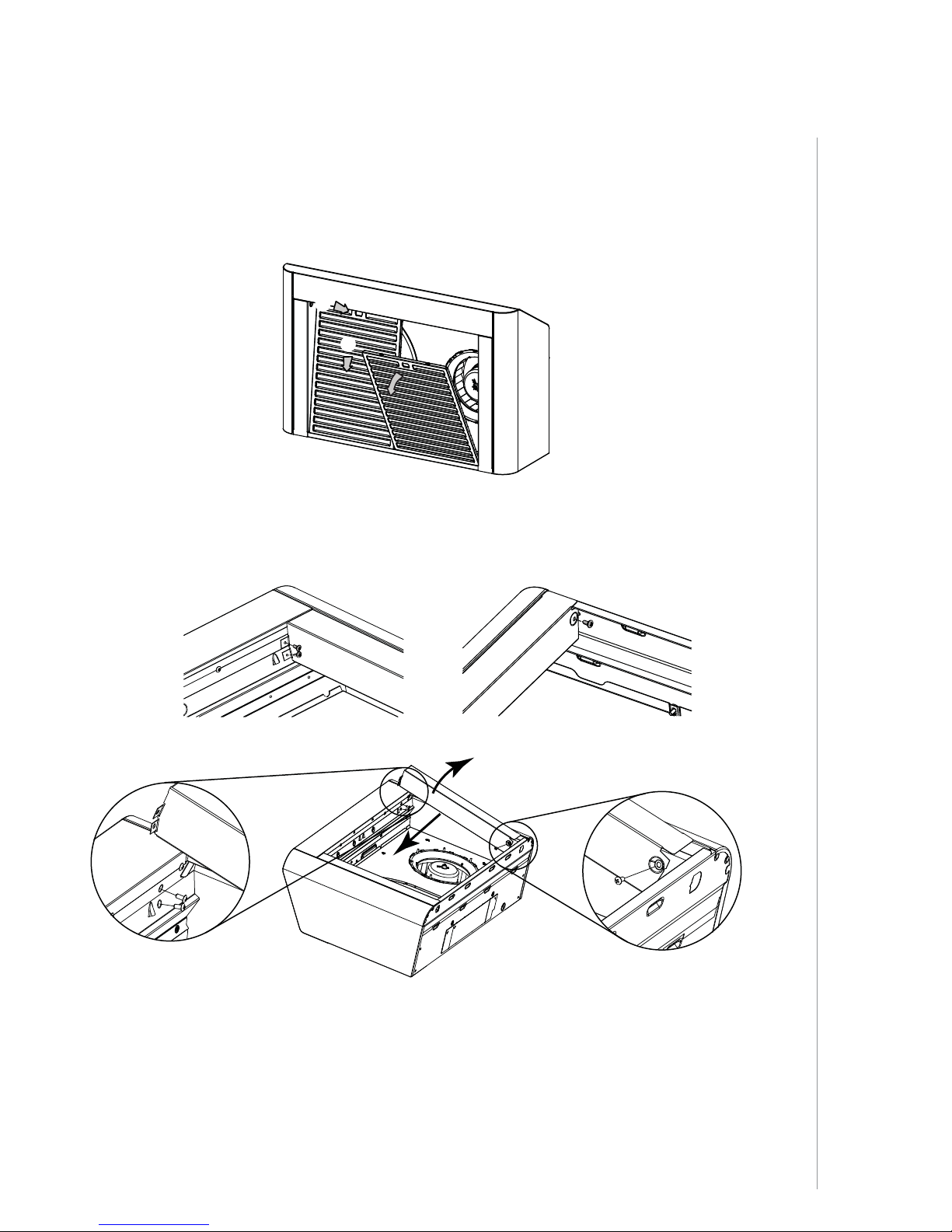
Prepare the Hood
1 ] If present, remove all protective polyfilm from the hood and/or parts.
2 ] Using the finger cup, remove the grease filters from the hood by pushing down and tilting
filters out .
B
C
3 ] Remove both fillers by removing the 3 screws holding each one of them. Slide each one
towards the center of the hood and tilt it up to remove it completely. Set the fillers and screws
aside.
c
d
INSTALLATION
INSTALLATION MANUAL
9
4 ] Remove the screw holding the 3¼” x 10” adapter/damper as well as the one for the 3¼” x 14”
adapter/damper, remove their tape strips and and put the adapter/dampers aside. Save these
screws, they will be used later to hold the blower cover plate.
5 ] Remove both tape strips holding the 7” round adapter, and put the adapter aside.
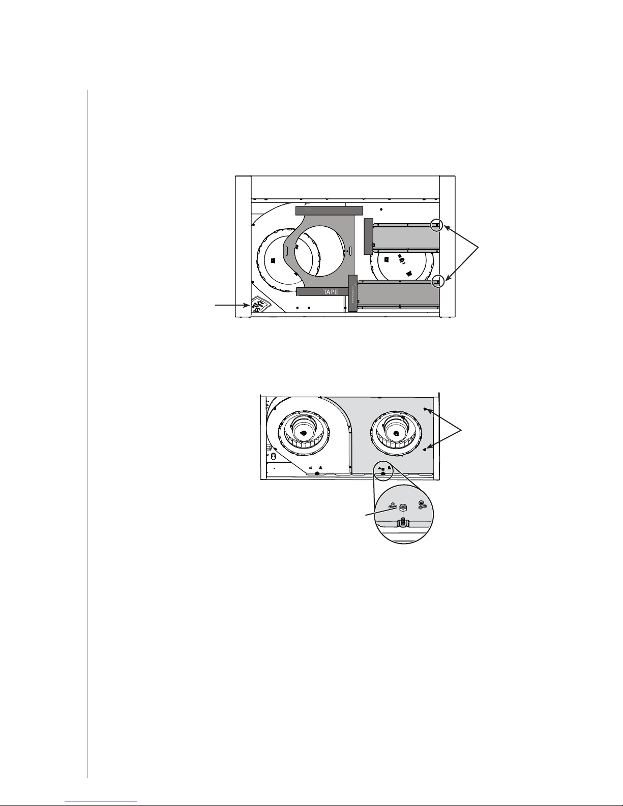
6 ] Remove the parts bag taped in the lower left corner of the hood.
TAPE
TAPE
TAPE
PARTS BAG
7 ] Using a 11/32” nut driver or socket, remove the lock nut retaining the flange of the right
blower cover plate (shaded part on illustration below) to the inner back of hood (see inset).
Remove the right cover plate remaining retaining screws (5 screws), then set the blower
cover along with its screws and nut aside.
BACK OF HOOD
4
5
LOCK NUT
TAPE
23
1
REMOVE
AND SAVE
THESE
SCREWS
SCREWS REMOVED
IN STEP 4
NOTE: For 30 in.-wide hoods, slightly lift up the cover plate before sliding it towards the left to
remove it.
INSTALLATION MANUAL
INSTALLATION
10
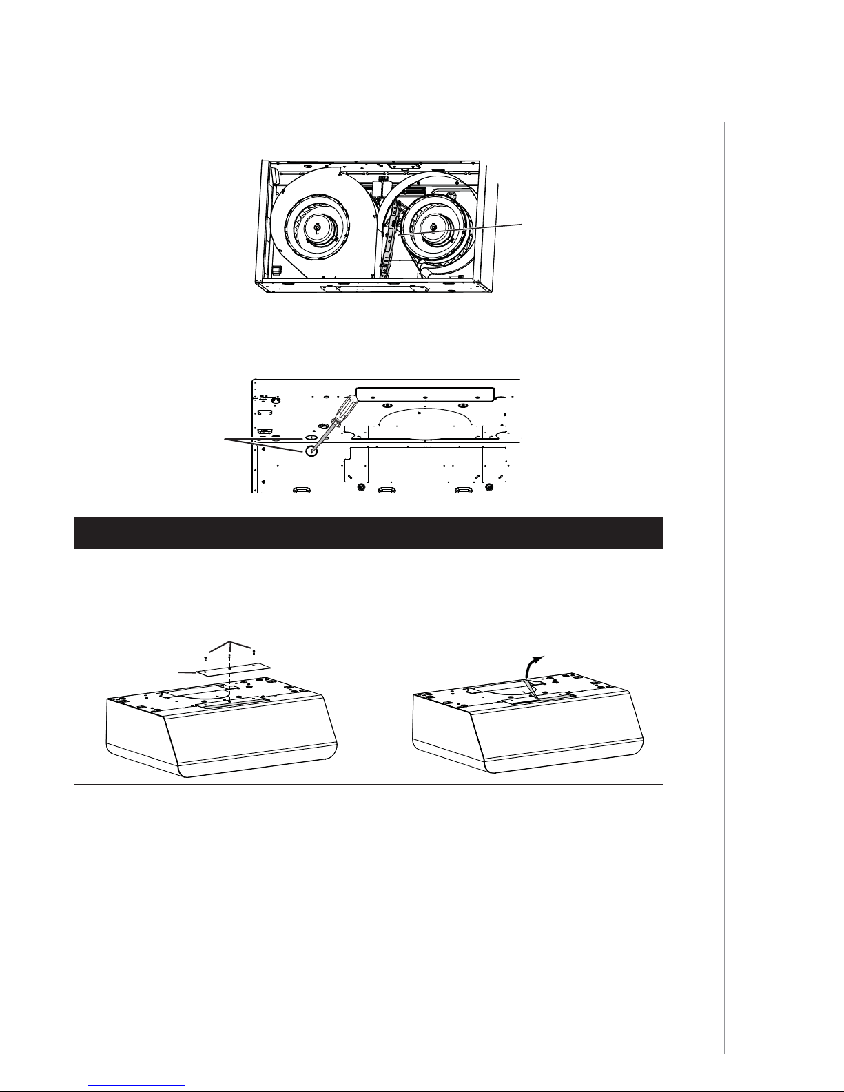
8 ] Remove the EZ1 brackets from inside the hood by cutting off the tie wrap. Discard the tie
wrap.
EZ1
BRACKETS
9 ] Remove Electrical Power Cable Knockout from top (vertical exhaust) or back (horizontal
exhaust) of hood. For knockout removed from back of hood, install an appropriate strain
relief, 1/2” diameter (not included). For knockout removed from top of hood, the strain relief
will be installed later.
ELECTRICAL
POWER CABLE
KNOCKOUT
NON-DUCTED INSTALLATION ONLY
10 ] Remove the 3 screws retaining the recirculation cover plate to the hood. Discard this plate
with its screws.
11 ] Peel off and discard the membrane covering the recirculation grille, ensuring the openings
are totally cleared.
SCREWS
RECIRCULATION
COVER PLATE
INSTALLATION
INSTALLATION MANUAL
11
 Loading...