

Page 1
MODEL HLB6
IN-LINE BLOWER
For use with Broan Elite and NuTone Premier Hoods.
READ AND SAVE THESE INSTRUCTIONS
Page 1
!
FOR DOMESTIC COOKING ONLY
WARNING
TO REDUCE THE RISK OF FIRE, ELECTRIC SHOCK, OR INJURY TO PERSONS, OBSERVE THE FOLLOWING:
1. Use this unit only in the manner intended by the manufacturer.
If you have questions, contact the manufacturer at the address
or telephone number listed in the warranty.
2. Before servicing or cleaning unit, switch power off at service
panel and lock the service disconnecting means to prevent power
from being switched on accidentally. When the service disconnecting means cannot be locked, securely fasten a prominent
warning device, such as a tag, to the service panel.
3. Installation work and electrical wiring must be done by a qualified person(s) in accordance with all applicable codes and standards, including fire-rated construction codes and standards.
4. Sufficient air is needed for proper combustion and exhausting
of gases through the flue (chimney) of fuel burning equipment
to prevent backdrafting. Follow the heating equipment
manufacturer’s guideline and safety standards such as those
published by the National Fire Protection Association (NFPA),
and the American Society for Heating, Refrigeration and Air Conditioning Engineers (ASHRAE), and the local code authorities.
5. When cutting or drilling into wall or ceiling, do not damage electrical wiring and other hidden utilities.
6. Ducted fans must always be vented to the outdoors.
7. To reduce the risk of fire, use only metal ductwork.
8. If this unit is to be installed over a tub or shower, it must be
marked as appropriate for the application and be connected to
a GFCI (Ground Fault Interrupter) - protected branch circuit.
9. Never place a switch where it can be reached from a tub or
shower.
10. This unit must be grounded.
TO REDUCE THE RISK OF A RANGE TOP GREASE FIRE:
A. Never leave surface units unattended at high settings. Boilovers
cause smoking and greasy spillovers that may ignite. Heat oils
slowly on low or medium settings.
B. Always turn hood ON when cooking at high heat or when
flambeing food (i.e. Crepes Suzette, Cherries Jubilee, Peppercorn Beef Flambe’).
C. Clean ventilating fans frequently. Grease should not be allowed
to accumulate on fan or filter.
D. Use proper pan size. Always use cookware appropriate for the
size of the surface element.
TO REDUCE THE RISK OF INJURY T O PERSONS IN THE EVENT
OF A RANGE TOP GREASE FIRE, OBSERVE THE FOLLOWING:*
1. SMOTHER FLAMES with a close-fitting lid, cookie sheet, or metal
tray, then turn off the burner. BE CAREFUL TO PREVENT
BURNS. If the flames do not go out immediately, EVACUATE
AND CALL THE FIRE DEPARTMENT.
2. NEVER PICK UP A FLAMING PAN - You may be burned.
3. DO NOT USE WATER, including wet dishcloths or towels - violent steam explosion will result.
!
WARNING
4. Use an extinguisher ONLY if:
A. You know you have a Class ABC extinguisher and you already
know how to operate it.
B. The fire is small and contained in the area where it started.
C. The fire department is being called.
D. You can fight the fire with your back to an exit.
* Based on “Kitchen Fire Safety Tips” published by NFPA.
CAUTION
1. For general ventilating use only. Do not use to exhaust hazard-
ous or explosive materials and vapors.
2. To avoid motor bearing damage and noisy and/or unbalanced
impellers, keep drywall spray, construction dust, etc. off power
unit.
3. If ventilator is installed in an unconditioned space (such as
an attic): Surround the ventilator with thermal insulation - to
minimize possible condensation.
4. Please read specification label on product for further informa-
tion and requirements.
TABLE OF CONTENTS
This manual is divided into sections as follows:
• “TYPICAL INSTALLATION”
This section shows a common installation.
- Mounting (New Frame Construction)
- Mounting (Existing Frame Construction)
- Mounting Using Hanger Kit (included)
- Ducting (straight-through blower discharge)
- Wiring
• “MOUNTING OPTIONS”
• “WIRING OPTIONS”
- Wiring Plate Position
• “DUCTING OPTIONS”
- Blower Discharge Positions
- Ducting (vertical blower discharge)
• “USE AND CARE”
• “SERVICE PARTS”
• “WARRANTY”
Installer: Leave this manual with
the homeowner .
Homeowner: Use and Care
information on page 4.
!
Page 2

Page 2
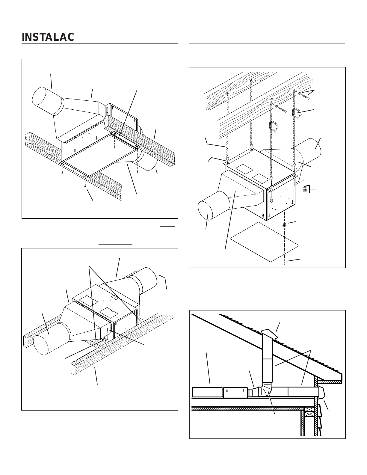
TYPICAL INSTALLATION
MOUNTING
10” ROUND DUCT
Blower factory-shipped
in horizontal
discharge position.
Factory-shipped unit installed in new construction.
(New Frame Construction)
4½” X 18½”
TO 10” ROUND
TRANSITION
MOUNTING
SCREW
Mounting brackets
factory-shipped in
position for ½”
ceiling material.
4½” X 18½”
TO 10” ROUND
TRANSITION
CEILING
JOIST
(24” centers
shown)
10” ROUND
DUCT
TYPICAL INSTALLATION
MOUNTING USING HANGER KIT (included)
HANGER
KIT BOLT
& WASHER
EXTENSION
SPRING
HANGER
KIT CHAIN
HANGER
KIT
EYE-BOLT
4½” X 18½”
TO 10”
ROUND
TRANSI-
TION
10” ROUND
DUCT
(OUTLET)
10” ROUND
DUCT (INTAKE)
HANGER
KIT NUT &
WASHER
MOUNTING
BRACKET
GRILLE NUT
(Install into
square holes in
housing)
MOUNTING
4½” X 18½”
TO 10” ROUND
TRANSITION
10” ROUND
DUCT
MOUNTING
BRACKETS
(Attached to
opposite sides
of housing &
upside-down,
so housing is
flush with
finished ceiling)
(Existing Frame Construction)
2 X 4 FRAMING
(wide side down)
CEILING JOIST
(24” centers
shown)
4½” X 18½” TO 10”
ROUND TRANSITION
10” ROUND
DUCT
MOUNTING
SCREW
ACCESS
PANEL
ACCESS
PANEL SCREW
Blower factory-shipped in straight-through
discharge position.
DUCTING
10”
ROUND
DUCT
(Straight-through blower discharge)
ROOF CAP
4½” X 18½”
TO 10” ROUND
TRANSITION
10”
ROUND
DUCT
10”
ROUND
ELBOW
Two ways to connect ductwork to a factory-shipped unit.
WALL
CAP
Blower factory-shipped in straight-through
discharge position.
IMPORTANT:
Remove the shipping tape from the damper flap and make sure
that damper flap opens and closes freely inside the ductwork. Use
duct tape to make ductwork connections secure and air-tight.
Remove shipping tape from damper
Page 3
Page 3
WIRING
BLACK
TO
BLACK
GROUND TO
WIRING PLATE
WHITE
TO
WHITE
TOP / BACK
OF HOUSING
WIRING
PLATE
120 VAC
LINE IN
(from
range
hood)
Ventilator can be wired from outside of housing.
Use UL approved connectors to wire per local codes.
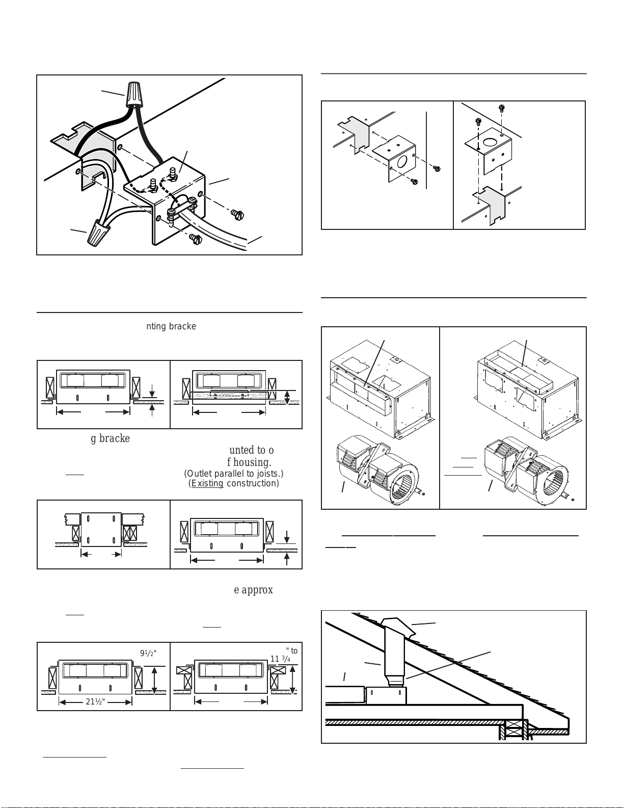
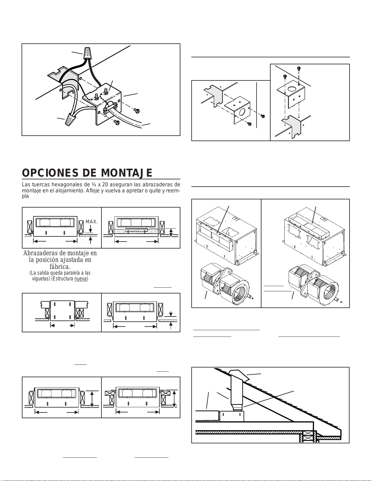
MOUNTING OPTIONS
¼-20 hex nuts secure mounting brackets to housing. Loosen and
re-tighten or remove and replace nuts as necessary for desired
mounting bracket position.
WIRING OPTIONS
WIRING PLATE POSITION
HORIZONTAL POWER
CABLE CONNECTION
Wiring plate mounts to side or top of housing.
DUCTING OPTIONS
BLOWER DISCHARGE POSITIONS
DUCT CONNECTOR
DUCT CONNECTOR
VERTICAL
POWER
CABLE
CONNECTION
1
/
1
MAX.
21½"
Mounting brackets in
factory-shipped position.
(Outlet parallel to joists.)
(New construction)
12¼"
Mounting brackets mounted
to outlet sides of housing.
(Outlet perpendicular to joists.)
(New construction)
1
9
/
2
" to
1
10
/
8
"
21½"
Mounting brackets flipped
over and mounted to outlet
sides of housing.
(Outlet parallel to joists.)
(Existing construction)
21½"
Mounting brackets flipped
over to give approx. 1”
more clearance.
(Outlet parallel to joists.)
(New construction)
2
"
10
11
1½"
2½"
1
2
3
/
to
Change
blower
& duct
connector
positions
for right
angle
discharge.
1
/
2
"
to
1
/
2
"
BLOWER
Blower and duct connector
straight-through dis-
in
charge position. (Factory
BLOWER
Blower and duct connector
right angle discharge
in
position.
shipped)
DUCTING
4
" to
3
/
4
"
10”
ROUND
DUCT
(Right angle blower discharge)
ROOF CAP
4½” X 18½”
TO 10” ROUND
TRANSITION
21½"
Mounting brackets mounted
to top of sides of housing.
(Outlet parallel to joists.)
(New or existing construction)
21½"
Mounting brackets flipped
over and mounted to top of
sides of housing.
(Outlet parallel to joists.)
(New or existing construction)
Typical ductwork connection to a ventilator converted to
right angle discharge.
Page 4
USE AND CARE
Follow wiring instructions packed with range hood, and adhere to
all local and state codes, and the National Electrical Code.
WARNING: To reduce the risk of electric shock,
disconnect from power supply before servicing.
Page 4
T o clean blower assembly: Remove access panel, unplug blower
from housing, remove blower mounting nuts, and carefully remove
blower from housing. Use appropriate vacuum attachment or a
soft cloth and mild soap or detergent to clean blower discharge
area and wheel. DO NOT ALLOW WATER TO ENTER MOTOR.
Make sure blower assembly is completely dry before reinstalling.
Motor is permanently lubricated. Do not oil or disassemble motor.
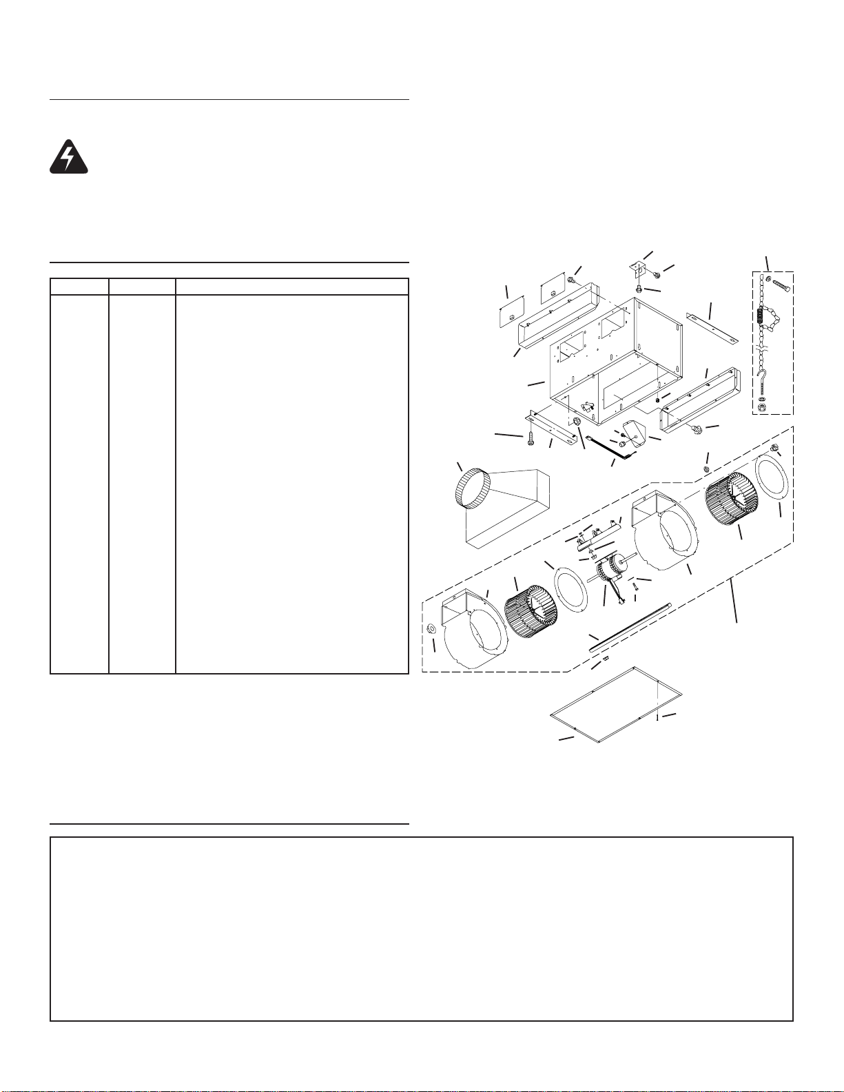
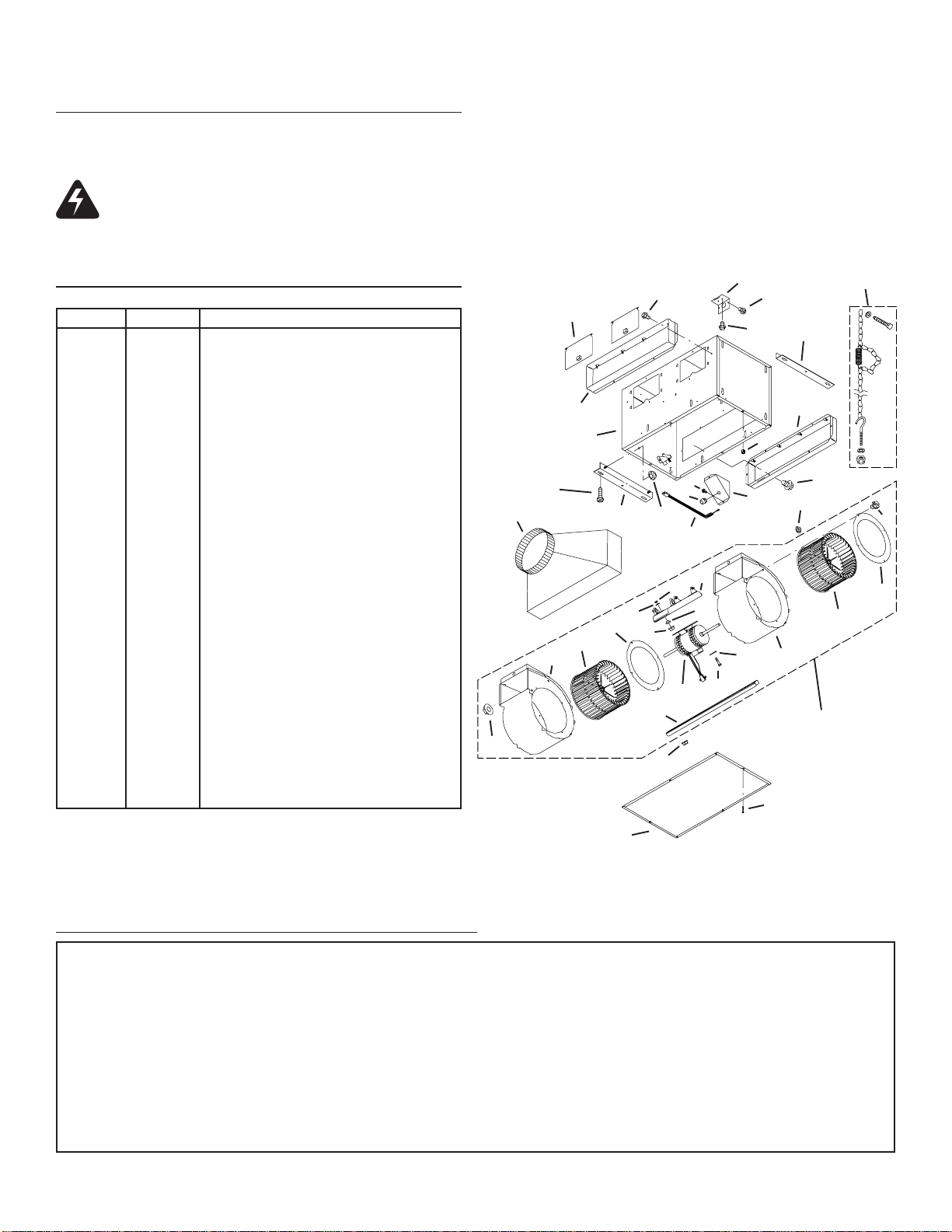
SERVICE PARTS
KEY NO. PART NO. DESCRIPTION
1 97014744 Housing Assembly
2 97014728 Mounting Bracket (2 req.)
3 98009449 Duct Connector (2 req.)
4 97014822 Damper Flap Assembly (2 req.)
5 99150415 Screw, 8-18 x ¼ (18 req.)*
6 98005512 Wiring Plate
7 99150471 Ground Screw, 10-32 x ½ (2 req.)
8 98005513 Wire Box Cover
9 99400035 Strain Relief Bushing
10 97006039 Wire Harness
11 99260477 Nut, ¼-20 (12 req.)*
12 97014745 Scroll Assembly (2 req.)
13 99020273 Blower Wheel (2 req.)
14 98009399 Inlet Ring (2 req.)
15 99080488 Motor
16 97014794 Motor Mounting Bracket
17 99100497 Rubber Isolator (4 req.)
18 99160380 Screw, 10-24 x 7/8 (4 req.)*
19 99250399 Washer (4 req.)*
20 99260306 Nut, Hex 10-24 (4 req.)*
21 99250254 Washer (4 req.)*
22 93260456 Nut, Hex Flange 3/8-16
23 98009461 Scroll Mounting Channel
+ 97016793 Blower Assembly, Complete
(Includes Key Nos. 5 & 11-23)
24 98009464 Access Panel
25 99420470 Access Panel Nut (4 req.)
26 99150472 Access Panel Mounting Screw (4 req.)
27 99150591 Screw, 10-16 x 7/8 (4 req.)
28 97016791 Hanger Kit
29 S423 Transition 4.5 x 18” to 10” Round
Order replacement parts by PART NO. - not by KEY NO.
* Standard hardware - may be purchased locally..
+ Not shown assembled.
11
5
4
3
1
5
9
11
29
27
2
10
20
21
14
13
22
12 12
15
23
11
16
17
18
6
19
5
7
25
8
28
2
3
5
11
5
14
13
BLOWER
ASSEMBLY
26
24
WARRANTY
Broan-NuTone warrants to the original consumer purchaser of its products that such products will be free from defects in materials or workmanship for a period of one year from the date of
original purchase. THERE ARE NO OTHER WARRANTIES, EXPRESS OR IMPLIED, INCLUDING, BUT NOT LIMITED TO, IMPLIED WARRANTIES OF MERCHANTABILITY OR FITNESS
FOR A PARTICULAR PURPOSE.
During this one-year period, Broan-NuTone will, at its option, repair or replace, without charge, any product or part which is found to be defective under normal use and service.
THIS WARRANTY DOES NOT EXTEND TO FLUORESCENT LAMP STARTERS AND TUBES. This warranty does not cover (a) normal maintenance and service or (b) any products or parts
which have been subject to misuse, negligence, accident, improper maintenance or repair (other than by Broan-NuTone), faulty installation or installation contrary to recommended installation
instructions.
The duration of an implied warranty is limited to the one-year period as specified for the express warranty. Some states do not allow limitation on how long an implied warranty lasts, so the
above limitation may not apply to you.
BROAN-NUTONE’S OBLIGATION TO REPAIR OR REPLACE, AT BROAN-NUTONE’S OPTION, SHALL BE THE PURCHASER’S SOLE AND EXCLUSIVE REMEDY UNDER THIS
WARRANTY. BROAN-NUTONE SHALL NOT BE LIABLE FOR INCIDENTAL, CONSEQUENTIAL OR SPECIAL DAMAGES ARISING OUT OF OR IN CONNECTION WITH PRODUCT USE
OR PERFORMANCE. Some states do not allow the exclusion or limitation of incidental or consequential damages, so the above limitation may not apply to you.
This warranty gives you specific legal rights, and you may also have other rights, which vary from state to state. This warranty supersedes all prior warranties.
To qualify for warranty service, you must (a) notify Broan-NuTone at the address stated below or telephone: 1-800-637-1453, (b) give the model number and part identification and (c) describe
the nature of any defect in the product or part. At the time of requesting warranty service, you must present evidence of the original purchase date.
In the U.S., contact: Broan-NuTone LLC, 926 West State Street, Hartford, WI U.S.A. 53027
In Canada, contact: Broan-NuTone Canada, 1140 Tristar Drive Mississauga, Ontario L5T 1H9 (905-670-2500)
BROAN-NUTONE ONE YEAR LIMITED WARRANTY
99043700B
Page 5
MODELO HLB6
VENTILADOR PARA MONTAJE EN LÍNEA
Por uso con campanas de Broan Elite y NuTone Premier.
LEA Y CONSERVE ESTAS INSTRUCCIONES
Página 5
!
PARA COCINAR EN CASA SOLAMENTE
ADVERTENCIA
PARA REDUCIR EL RIESGO DE INCENDIO, GOLPE ELÉCTRICO, O LESIÓN
A PERSONAS, OBSERVE LO SIGUIENTE:
1. Use esta unidad solamente de la manera indicada por el fabricante. Si tiene
preguntas, póngase en contacto con el fabricante a la dirección o teléfono
que aparecen en la garantía.
2. Antes de limpiar o de poner en servicio la unidad, apague el interruptor en el
panel de servicio, y asegure el panel de servicio para evitar que se encienda
accidentalmente. Cuando el dispositivo para desconectar el servicio eléctrico
no puede ser cerrado con algún tipo de traba, sujete fuertemente al panel de
servicio, una etiqueta de advertencia prominente.
3. El trabajo de instalación y cableado eléctrico deben estar hechos por personal
capacitado de acuerdo con todos los códigos y estándares aplicables,
incluyendo códigos y estándares de construcción a prueba de incendios.
4. Se necesita suficiente aire para la combustión y extracción de gases por la
chimenea del equipo que quema combustible para evitar la retrogresión de
las llamas. Siga las directrices del fabricante y estándares de seguridad como
los publicados por la Asociación Nacional de Protección Contra Incendios (o
por sus siglas en inglés NFPA), y la Sociedad Americana de Ingenieros de
Calefacción, Refrigeración, y Aire Acondicionado (o por sus sigles en inglés
ASHRAE), y los códigos de las autoridades locales.
5. Cuando corte o taladre en una pared o cielo raso, no dañe cableado eléctrico
o instalaciones no visibles.
6. Ventiladores con conductos siempre deben extraer hacia el exterior.
7. Para reducir el riesgo de incendio, use sólo ductos de metal.
8. Si esta unidad va a instalarse sobre una bañera o ducha, debe marcársela
como correcta para dicha aplicación y debe conectarse a un protegido GFCI
(Cortacicuito Accidental a Tierra).
9. Nunca instale un interruptor donde se pueda alcanzar desde una bañera o
ducha.
10. Esta unidad se debe conectar a tierra.
P ARA REDUCIR EL RIESGO DE INCENDIO DEBIDO A GRASA ACUMULADA
EN LAS HORNILLAS:
1. Nunca deje sin atender las unidades de superficie cuando tengan ajustes
altos. Los reboses pueden provocar humo y derrames grasosos que se pueden
incendiar. Caliente lentamente el aceite en un ajuste bajo o medio.
2. Siempre ENCIENDA la campana cuando cocine con alta temperatura o cuando
cocine alimentos que se puedan incendiar.
3. Limpie con frecuencia los ventiladores. No debe permitir que la grasa se
acumule en el ventilador ni en el filtro.
4. Utilice un sartén de tamaño adecuado. Siempre utilice el utensilio adecuado
al tamaño del elemento de superficie.
PARA REDUCIR EL RIESGO DE LESION A PERSONAS RESULT ADO DE UN
INCENDIO DEBIDO A GRASA ACUMULADA EN LAS HORNILLAS, PROCURE
LO SIGUIENTE:*
1. AHOGUE LAS LLAMAS con una tapa ajustada o charola de metal, después
apague la hornilla. TENGA CUIDADO A FIN DE EVITAR QUEMADURAS. Si
las llamas no se apagan de inmediato, EV ACUE Y AVISE A LOS BOMBEROS.
2. NO LEVANTE NUNCA UNA SARTEN QUE ESTE EN LLAMAS - Usted se
podrá quemar.
3. NO UTILICE AGUA, incluyendo toallas de cocina mojadas - puede resultar
ADVERTENCIA
una explosión de vapor violenta.
4. Utilice un extinguidor SOLAMENTE si:
A. Usted sabe que tiene un extinguidor de clas ABC y lo sabe utilizar.
B. El incendio es pequeño y contenido dentro del área donde se inició.
C. Los bomberos han sido avisados.
D. Usted puede combatir el incendio con una salida a su espalda.
* Basado en las recomendaciones para “Seguridad en la Cocina” publicadas por
la NFPA de los EEUU.
CUIDADO
1. Para uso de ventilación general solamente. No lo use para extraer materiales
o vapores peligrosos o explosivos.
2. Para evitar daño a los cojinetes del motor y hélices ruidosas y/o
desequilibradas, mantenga la unidad de potencia lejos de rocíos de yeso,
polvo de construcción, etc.
3. Si el ventilador se instala en un área sin acondicionamiento (como por
ejemplo en un ático): Rodee el ventilador con material de aislamiento térmico
para minimizar la posible condensación.
4. Para más información y requisitos favor leer la etiqueta de especificaciones
del producto.
CONTENDIO
Este manual consiste en las siguientes secciones:
• “INSTALACIÓN TÍPICA”
Esta sección muestra una instalación común en una estructura nueva y en
una existente.
- Montaje (estructura nueva)
- Montaje (estructura existente)
- Montaje el usar kit de suspender
- Conexiones eléctricas
- Colocación de conductos (descarga derecho por del
ventilador)
• “OPCIONES DE MONTAJE”
• “OPCIONES PARA LA CONEXIÓN ELÉCTRICA”
- Colocación de la placa de conexiones
• “OPCIONES PARA LA COLOCACIÓN DE CONDUCTOS”
- Posiciones de la descarga del ventilador
- Colocación de conductos (descarga ángulo recto del
ventilador)
• “USO Y CUIDADO”
• “PIEZAS DE SERVICIO”
• “GARANTÍA”
Instalador: Deje este manual con el
dueño de casa.
Dueño de casa: Información del uso y
mantenimiento en la página 8.
!
!
Page 6
Página 6
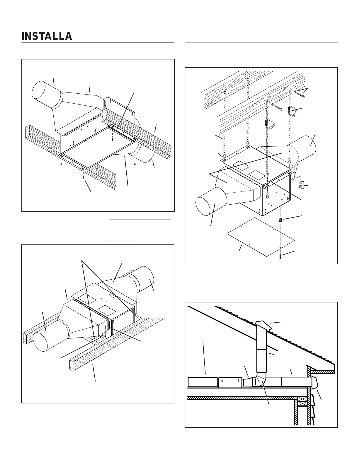
INSTALACIÓN TÍPICA
MONTAJE (
CONDUCTO REDONDO
DE 25,4 cm (10 po)
Ventilador, enviado de
fábrica en posición
de descarga horizontal
Unidad enviada de fábrica instalada en una estructura nueva.
MONTAJE (
ESTRUCTURA DE 5,08 x 10,2 cm (2 x 4 po)
(con el lado del cableado hacia abajo)
Estructura nueva
TRANSICIÓN
11,4 X 47 a 25,4 c m
(4½ X 18½ a 10 po)
TORNILLO
DE MONTAJE
)
posición para montarse en
una vigueta de ½” (1,27 cm)
11,4 X 47 a 25,4 c m
(4½ X 18½ a 10 po)
Estructura existente
TRANSICIÓN 11,4 X 47 a 25,4 cm
(4½ X 18½ a 10 po)
Abrazaderas de montaje,
enviadas de fábrica en
del techo.
VIGUETA DEL TECHO
(se muestran
centros de
61 cm (24 po)
CONDUCTO
REDONDO
DE 25,4 cm (10 po)
TRANSICIÓN
)
INSTALACIÓN TÍPICA
MONTAJE EL USAR KIT DE SUSPENDER
(incluido)
TORNILLO Y
ARANDELA
DE KIT DE
SUSPENDER
RESORTE
EXTENCIÓN
CADENA DE
KIT DE
SUSPENDER
TORNILLO DE
OJO DE KIT DE
SUSPENDER
CONDUCTO
REDONDO
DE 25,4 cm
(10 po)
TRANSICIÓN
11,4 X 47 a 25,4 cm
(4½ X 18½ a 10 po)
PANEL DE ACCESO
CONDUCTO
REDONDO
DE 25,4 cm (10 po)
TRANSICIÓN
11,4 X 47 a 25,4 c m
(4½ X 18½ a 10 po)
TUERCA Y
ARANDELA
DE KIT DE
SUSPENDER
TUERCA DE PANEL DE
ACCESO (Instale en los
agujeros pequeños en la
cubierta)
TORNILLO DE
PANEL DE ACCESO
TRANSICIÓN
11,4 X 47 a 25,4 c m
(4½ X 18½ a 10 po)
CONDUCTO
REDONDO DE
25,4 cm (10 po)
(SALIDA)
ABRAZADERAS DE
MONTAJE
(conectadas a los
lados opuestos del
alojamiento y hacia
abajo para que el
alojamiento quede a
nivel del cielo raso
terminado)
VIGUETA DEL TECHO
(se muestran centros
de 24” (61 cm)
CONDUCTO
REDONDO DE
25,4 cm (10 po)
(ADMISION)
TORNILLO
DE MONTAJE
Ventilador, enviado de fábrica en posición de descarga
derecho por del ventilador.
NOTA: Asegúrese de quitar la cinta que fija la pestaña del regulador durante la transportación, y de que esta pestaña abra y cierre
libremente dentro del conducto. Utilice cinta de conductos para
asegurar y hermetizar las conexiones de los conductos.
Ventilador, enviado de fábrica en posición de descarga
derecho por del ventilador.
COLOCACIÓN DE CONDUCTOS
(descarga
derecha por del ventilador)
VENTILACIÓN EN EL ALERO
CONDUCTO
REDONDO DE
25,4 cm (10 po)
TRANSICIÓN
11,4 X 47 a 25,4 c m
(4½ X 18½ a 10 po)
CODO REDONDO
DE 25,4 cm (10 po)
Dos formas de conectar los conductos a una unidad
enviada de fábrica.
CONDUCTO
REDONDO DE
25,4 cm (10 po)
TAPA DEL
TECHO
Page 7
Página 7
CABLEADO
NEGRO A
NEGRO
TIERRA A LA PLACA DE
BLANCO
A
BLANCO
El ventilador se puede conectar desde el exterior del alojamiento.
Use conectores apr obados por UL en la conexión en cumplimien-
to con los códigos locales.
PARTE SUPERIOR/
POSTERIOR DEL
ALOJAMIENTO
CONEXIONES
PLACA DE
CONEXIONES
LÍNEA DE
ENTRADA DE
120 VCA
(de la campana)
OPCIONES DE MONTAJE
Las tuercas hexagonales de ¼ x 20 aseguran las abrazaderas de
montaje en el alojamiento. Afloje y vuelva a apretar o quite y reemplace las tuercas según sea necesario para colocar las abrazaderas
de montaje en la posición deseada.
2,9
1
cm
/
1
MAX.
8
"
3,8
1½"
a
to
6,4
2½"
cm
OPCIONES PARA LA CONEXIÓN
ELÉCTRICA
COLOCACIÓN DE LA
PLACA
DE CONEXIONES
CONEXIÓN
VERTICAL DEL
CABLE DE
ALIMENTACIÓN
CONEXIÓN
HORIZONTAL
DEL CABLE DE
ALIMENTACIÓN
La placa de conexiones se monta a los lados o en la parte
superior del alojamiento.
OPCIONES P ARA LA
COLOCACIÓN DE CONDUCTOS
POSICIONES DE LA DESCARGA DEL VENTILADOR
CONECTOR DEL CONDUCTO
CONECTOR DEL CONDUCTO
21½"
54,6 cm
Abrazaderas de montaje en
la posición ajustada en
fábrica.
(La salida queda paralela a las
viguetas) (Estructura
31,1 cm
nueva)
12¼"
Abrazaderas de montaje
montadas en los lados de la
salida del alojamiento.
(La salida queda perpendicular a las
viguetas) (Estructura nueva)
24,1 a
1
9
/
2" to
1
26,7 cm
10
/
2"
21½"
54,6 cm
21½"
54,6 cm
Abrazaderas de montaje
volteadas y montadas a los
lados de la salida del
alojamiento.
(La salida queda perpendicular a las
viguetas) (Estructura existente)
1
1
/
2
"
3,8 a
to
6,4
1
/
2
"
2
cm
54,6 cm
21½"
Abrazaderas de montaje
volteadas para permitir un
espacio adicional de aprox.
1” (2.54 cm).
(La salida queda paralela a las
viguetas) (Estructura
54,6 cm
21½"
nueva)
3
27,3 a
10
/
3
29,9 cm
11
4
" to
/
4
"
VENTILADOR
Conector del ventilador y
del conducto en posición
de descarga derecha por
del ventilador. (ajuste de
fábrica)
COLOCACIÓN DE DUCTOS
ventilador)
CONDUCTO
REDONDO DE
25,4 cm (10 po)
Cambie la
posición del
conector
del ventilador
y del
conducto
para una
descarga
ángulo recto.
VENTILADOR
Cambie la posición del
conector del ventilador y
del conducto para una
descarga ángulo recto.
(Descarga ángulo recto del
TAPA DEL TECHO
TRANSICIÓN
11,4 X 47 a 25,4 c m
(4½ X 18½ a 10 po)
Abrazaderas de montaje
montadas en la parte
superior de los lados del
alojamiento.
(La salida queda paralela a las
viguetas) (Estructura nueva o existente)
Abrazaderas de montaje
volteadas y montadas en la
parte superior de los lados
del alojamiento.
(La salida queda paralela a las viguetas)
(Estructura
nueva o existente)
Conexión típica de los conductos al ventilador cambiado a
descarga ángulo recto.
Page 8
USO Y CUIDADO
Siga las instrucciones para las conexiones eléctricas que vienen
empacadas con el campana, y observe todos los códigos locales
y estatales y el Código Eléctrico Nacional.
ADVERTENCIA: Para reducir el riesgo de sufrir una
descarga eléctrica, antes de dar servicio al ventilador
desconéctelo del suministro eléctrico.
Página 8
Para limpiar el conjunto del ventilador: Quite el panel de acceso,
desconecte el ventilador del alojamiento, quite las tuercas de
montaje del ventilador y cuidadosamente saque el ventilador del
alojamiento. Use el aditamento apropiado de la aspiradora o un
paño suave y jabón o detergente suave para limpiar el área de
descarga y la rueda del ventilador. NO PERMITA QUE ENTRE
AGUA AL MOTOR. Asegúrese de que el conjunto del ventilador
esté completamente seco antes de volverlo a instalar.
El motor está permanentemente lubricado. No lubrique ni desmonte
el motor.
PIEZAS DE SERVICIO
CLAVE Nº. PIEZA Nº. DESCRIPCIÓN
1 97014744 Conjunto del alojamiento
2 97014728 Abrazaderas de montaje (se req. 2)
3 98009449 Conector del conducto (se req. 2)
4 97014822 Conjunto de la solapa de compuerta de
tiro (se req. 2)
5 99150415 Tornillos, 8-18 x ¼ (se req. 18)*
6 98005512 Placa de conexiones
7 99150471 Tornillos de conexión a tierra, 10-32 x ½
(se req. 2)
8 98005513 Cubierta de la caja de conexiones
9 99400035 Buje de alivio de tensión
10 97006039 Arnés de alambre
11 99260477 Tuercas, ¼-20 (12 req.)*
12 97014745 Conjunto del caracol (2 req.)
13 99020273 Rueda del ventilador
14 98009399 Anillo de entrada (2 req.)
15 99080488 Motor
16 97014794 Abrazadera montaje de motor
17 99100497 Aislador de caucho (se req. 4)
18 99160380 Tornillos, 10-24 x 7/8 (se req.4)*
19 99250399 Arandelas (se req. 4)*
20 99260306 Tuercas, hex 10-24 (se req. 4)*
21 99250254 Arandelas (se req. 4)*
22 93260456 Tuerca, hex pestaña 3/8-16
23 98009461 Ranura montaje de caracol
+ 97016793 Conjunto del ventilador, completo
(Incluye clave Nº.s 5 y 11-23)
24 98009464 Panel de acceso
25 99420470 Tuercas de panel de acceso (se req. 4)
26 99150472 Tornillos de montaje de pane de acceso
(se req. 4)
27 99150591 Tornillos, 10-16 x 7/8 (se req. 4)
28 97016791 Kit de suspender
29 S423 Transición, 11,4 X 47 a 25,4 cm
(4½ X 18½ a 10 po)
Pida las piezas de repuesto por Nº. DE PIEZA, no por Nº. DE
CLAVE
* Herraje estándar, se puede comprar localmente.
+ No demostrado montado.
11
5
4
3
1
5
9
11
29
27
2
10
20
21
14
13
22
12 12
15
23
11
24
16
17
18
6
5
7
25
8
11
19
CONJUNTO DE
VENTILADOR
26
28
2
3
5
5
14
13
GARANTIA
Broan le garantiza al consumidor comprador original de sus productos que tales productos estarán libres de defectos en materiales o mano de obra por un período de un año a partir de la fecha
de compra original. NO HAY OTRAS GARANTIAS EXPLICITAS O IMPLICITAS, INCLUYENDO, PERO NO LIMITADAS A GARANTIAS IMPLICITAS DE COMERCIALIZACION O APTITUD PARA
UN PROPOSITO PARTICULAR.
Durante este período de un año, Broan reparará o cambiará, a su opción y sin cobro, cualquier producto o pieza que se encuentre defectuosa bajo uso y servicio normal.
ESTA GARANTIA NO SE EXTIENDE A ARRANCADORES DE LAMPARAS FLUORESCENTES Y TUBOS. Esta garantía no cubre (a) mantenimiento y servicio normales o (b) cualquier producto
o pieza que hayan sido sometidos a uso equivocado, negligencia, accidente, mantenimiento o reparación indebida (excepto por Broan), instalación defectuosa o instalación contraria a las
instrucciones de instalación.
La duración de cualquier garantía implícita se limita a un período de un año según se especifica en la garantía explícita. Algunos estados no permiten limitación a la duración de una garantía
implícita, por lo que esta limitación tal vez no se aplica al caso suyo.
LA OBLIGACION DE BROAN DE REPARAR O CAMBIAR, A OPCION DE BROAN, SERA EL UNICO Y EXCLUSIVO REMEDIO AL COMPRADOR BAJO ESTA GARANTIA. BROAN NO SERA
RESPONSABLE POR DAÑOS INCIDENTALES, CONSECUENTES, O ESPECIALES QUE SURJAN DE O EN RELACION A EL USO O DESEMPEÑO DEL PRODUCTO. Algunos estados no
permiten la exlusión o limitación de daños incidentales o consecuentes, por lo que esta limitación o exclusión tal vez no se aplica en su caso.
Esta garantía le da derechos legales específicos, y usted puede tener otros derechos que varían de estado a estado. Esta garantía reemplaza todas las garantías anteriores.
Para calificar para servicio bajo esta garantía, usted debe (a) notificar a Broan en la dirección que aparece abajo o al teléfono 1-800-637-1453, (b) dar el número de modelo y la identificación de
pieza y (c) describir el defecto en el producto o pieza. Al solicitar servicio bajo la garantía, usted debe presentar evidencia de la fecha de compra original.
En los Estados Unidos, llame: Broan-NuTone LLC, 926 West State Street, Hartford, WI 53027 (1-800-637-1453)
En Canada, llame: Broan-NuTone Canada, 1140 Tristar Drive Mississauga, Ontario L5T 1H9 (905-670-2500)
GARANTIA LIMITADA DE BROAN DE UN AÑO
99043700B
Page 9

MODÈLE HLB6
VENTILATEUR MONTAGE DANS LIGNE
Pour usage avec Broan Elite et NuTone Premier hottes de cuissine.
LIRE ET CONSERVER CES INSTRUCTIONS
Page 9
!
POUR USAGE DOMESTIQUE SEULEMENT
AVERTISSEMENT
POUR RÉDUIRE LE RISQUE D´INCENDIE, DE CHOC ÉLECTRIQUE OU DE
BLESSURES PERSONNELLES, OBSERVEZ CE QUI SUIT:
1. Utilisez cette unité seulement de la façon prévue par le fabricant. Pour d´autres
renseignements, contactez le fabricant à l´adresse ou au numéro de téléphone
qui se trouve dans la garantie.
2. Avant d'effectuer une réparation ou un entretien sur cet appareil, coupez le
courant au tableau d'alimentation et verrouillez celui-ci pour empêcher que la
tension soit remise accidentellement. Lorsque le verrouillage de la déconnexion
n'est pas possible, mettez bien en vue un signal d'avertissement telle qu'une
étiquette, sur le panneau d'alimentation.
3. L´installation et la pose des fils électriques doivent être effectuées par une ou
des personnes qualifiées conformément à tous les codes et normes applicables,
incluant les normes de construction en rapport aux incendies.
4. Il faut suffisamment d´air pour une combustion appropriée et l´échappement
des gaz par le tuyau de la cheminée de l´équipement brûlant du combustible
pour prévenir un contre-courant. Suivez les instructions du fabricant de
l´équipement de chauffage et les normes de sécurité telles que celles publiées
par la National Fire Protection Association (NFPA) et l´American Society for
Heating, Refrigeration and Air Conditioning Engineers (ASHRAE) et des
autorités du code local.
5. Lors de la coupe ou du perçage dans un mur ou un plafond, prenez soin de ne
pas endommager les fils électriques et les autres utilités dissimulées.
6. La décharge des ventilateurs à conduit par l´évent doit toujours se faire à
l´extérieur.
7. Pour réduire le rsque d’incendie, utilisez seulement des donduits de ventilation en métal.
8. Si cette unité doit être installée au-dessus d’une baignoire ou d’une douche,
elle doit être marquée comme étant appropriée pour l’application et être
connectée à un circuit dérivé protége GFCI (interrupteur de circuit en cas de
défaut de mise à la terre du neutre).
9. Ne placez jamais un interrupteur dans un endroit où il peut être rejoint d’une
baignoire ou d’une douche.
10. Cette unité doit être mise à la terre.
AFIN DE DIMINUER LES RISQUES D’INCENDIE POUVANT SE DÉCLENCHER
SUR LA SURFACE DE CUISSON:
1. Ne jamais laisser sans surveillance des unités de surface réglées à feu vif. En
plus de générer de la fumée, les débordements de graisse peuvent prendre
feu. Chauffer les huiles lentement à feu doux ou moyen.
2. Toujours mettre en marche la hotte durant la cuisson à feu vif ou la cuisson
d’aliments à flamber.
3. Nettoyer régulièrement les ventilateurs d’aération. On ne doit tolérer aucune
accumulation de graisse sur le ventilateur ou sur le filtre.
4. Utiliser une casserole de grosseur appropriée. Toujours utiliser une batterie
de cuisine proportionnelle à l’élément de surface.
AFIN DE DIMINUER LES RISQUES DE BLESSURES POUVANT SURVENIR
LORSQU’UN FEU SE DÉCLENCHE SUR LA SURF ACE DE CUISSON, SUIVEZ
CES DIRECTIVES:
1. ÉTOUFFEZ LES FLAMMES avec un couvercle hermétique, une tôle à biscuits ou un plateau en métal puis éteignez la cuisinière. PRENEZ GARDE
AUX BRÛLURES. Si vous ne parvenez pas à éteindre immédiatement les
flammes, ÉVACUEZ LES LIEUX ET CONTACTEZ VOTRE POSTE LOCAL
DE LUTTE CONTRE LES INCENDIES.
2. NE VOUS EMPAREZ JAMAIS D’UN PLAT QUI S’EST ENFLAMMÉ – Vous
risqueriez de vous brûler.
AVERTISSEMENT
3. N’UTILISEZ JAMAIS D’EAU, incluant les linges à vaisselles ou serviettes
mouillés car cela peut provoquer une violente explosion de vapeur.
4. Utilisez un extincteur SEULEMENT si:
A. Il s’agit d’un extincteur de classe ABC et que vous savez
comment vous en servir.
B. Il s’agit d’un petit feu qui ne se propage pas ailleurs que sur la cuisinière.
C.Vous avez appelé votre poste local de lutte contre les incendies.
D. Vous pouvez combattre le feu tout en ayant accès à une sortie.
* Basé sur “Kitchen Fire Safety Tips” édité par NFPA.
ATTENTION
1. Pour ventilation générale seulement. Ne l´utilisez pas pour évacuer les vapeurs
ou matériaux dangereux ou que peuvent exploser.
2. Pour éviter d´endommager les coussinets du moteur et des turbines bruyantes
et/ou mal équilibrées, assurez que l´unité motrice est exempte de poussière
provenant des murs en pierres sèches et la construction.
3. Si le ventilateur est installé dans un endroit non conditionné (tel qu’un
grenier): Entourez le ventilateur d’un isolant thermique afin de réduire toute
condensation éventuelle.
4. Veuillez lire l´étiquette de spécifications sur le produit pour d´autres
renseignements et exigences.
TABLE DES MATIÈRES
Ce manuel se divise comme suit :
• INST ALLATION TYPIQUE
Cette section montre une installation standard dans un bâtiment
en cours de construction ou déjà construit.
- Montage (construction en cours)
- Montage (construction terminée)
- Montage (kit pour accrocher)
- Installation des conduits (décharge de soufflerie dans ligne)
- Câblage
• OPTIONS DE MONTAGE
• OPTIONS DE CÂBLAGE
- Position de la plaque de câblage
• OPTIONS D’INSTALLATION DES CONDUITS
- Positions de la décharge de la soufflerie
- Installation des conduits (décharge de soufflerie droit angle)
• UTILISATION ET ENTRETIEN
• PIÈCES DE RECHANGE
• GARANTIE
Installateur: Remetez ce manuel au
protpriétaire de maison.
Propriétaire de maison: Mode
d’utilisation et soin à la page 12.
!
!
Page 10
Page 10
INSTALLATION TYPIQUE
MONTAGE
CONDUIT
CIRCULAIRE
DE 10 po (25,4 cm)
Soufflerie préassemblée
en position de décharge
horizontale
Appareil installé dans un bâtiment en cours de construction.
MONTAGE
(Construction en cours)
TRANSITION
4½ X 18½ au 10 po
(11,4 x 47 au 25,4
cm) circulaire
VIS DE
FIXATION
plafonds de ½ po (1,27
TRANSITION
4½ X 18½ au 10 po
(11,4 x 47 au 25,4
cm) circulaire
(construction terminée)
CHARPENTE 2 x 4
(côté large en bas)
(11,4 x 47 au 25,4 cm) circulaire
TRANSITION
4½ X 18½ au 10 po
Supports
préassemblés pour
cm) d’épaisseur.
SOLIVE DE
PLAFOND
24 po (61
cm centre)
CONDUIT
CIRCULAIRE
DE 10 po (25,4 cm)
INSTALLATION TYPIQUE
MONTAGE EN UTILISANT LE KIT DE CINTRE
(inclus)
VIS ET
RONDELLE DE
LE KIT POUR
ACCROCHER
RESSORT DE
PROLONGATION
CHAÎNE
DE LE KIT
POUR
ACCROCHER
BOULON D’OEIL
DE LE KIT POUR
ACCROCHER
TRANSITION
4½ X 18½
au 10 po
(1 1,4 x 47
au 25,4 cm)
circulaire
CONDUIT
CIRCULAIRE DE
10 po (25,4 cm)
(SORTIE)
PANNEAU D’ACCESS
CONDUIT
CIRCULAIRE DE
10 po (25,4 cm)
(ADMISSION)
VIS ET
RONDELLE DE
LE KIT POUR
ACCROCHER
SUPPORTS
ÉCROU DE
PANNEAU
D’ACCESS (Installez
sur les trous carrés
dans le logement)
VIS DE PANNEAU
D’ACCESS
TRANSITION
4½ X 18½ au 10 po
(11,4 x 47 au 25,4
cm) circulaire
CONDUIT
CIRCULAIRE DE
10 po (25,4 cm)
(SORTIE)
SUPPORTS
(fixés aux
autres côtés
du boîtier et à
l’envers pour
que le boîtier
soit au ras du
plafond fini)
SOLIVE DE
PLAFOND 24 po
(61 cm) centre
CONDUIT
CIRCULAIRE
DE 10 po
(25,4 cm)
(ADMISSION)
VIS DE
FIXATION
Soufflerie préassemblée en position de décharge dans ligne.
REMARQUE : Veiller à retirer le ruban adhésif d’expédition du volet
du registre et s’assurer que ce dernier s’ouvre et se ferme librement
à l’intérieur du conduit. Utiliser du ruban adhésif pour assurer et
étancher les raccords des conduits.
Soufflerie préassemblée en position de décharge dans ligne.
INSTALLATION DES CONDUITS
(décharge de
soufflerie dans ligne)
CONDUIT
CIRCULAIRE DE
10 po (25,4 cm)
TRANSITION
4½ X 18½ au 10 po
(11,4 x 47 au 25,4
cm) circulaire
COUDE
CIRCULAIRE DE
10 po (25,4 cm)
Deux manières de raccorder les conduits à un appareil
prémonté.
CHAPEAU DE TOIT
CONDUIT
CIRCULAIRE DE
10 po (25,4 cm)
CHAPEAU
DE MUR
Page 11
Página 11
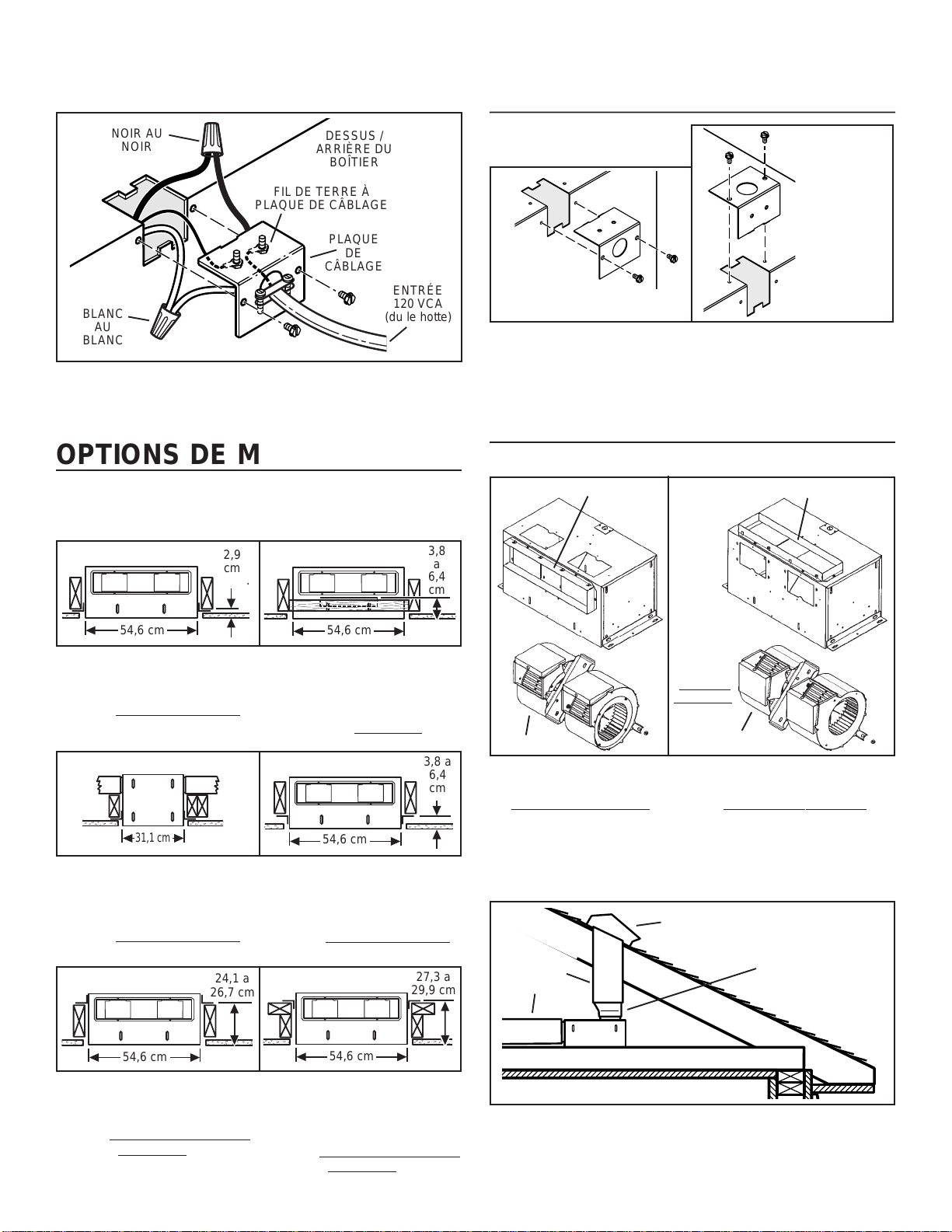
CÂBLAGE
NOIR AU
NOIR
FIL DE TERRE À
PLAQUE DE CÂBLAGE
BLANC
AU
BLANC
Le ventilateur peut être branché depuis l’extérieur du
boîtier. Utiliser des connecteurs homologués UL pour les
branchements, conformément aux codes locaux en vigueur.
DESSUS /
ARRIÈRE DU
BOÎTIER
PLAQUE
DE
CÂBLAGE
ENTRÉE
120 VCA
(du le hotte)
OPTIONS DE MONTAGE
Des écrous à six pans ¼-20 fixent les supports au boîtier. Desserrer
et resserrer ou retirer et replacer les écrous si nécessaire, selon la
position désirée pour le support.
OPTIONS DE CÂBLAGE
POSITION DE LA
PLAQUE DE CÂBLAGE
BRANCHEMENT
DU CÂBLE
D’ALIMENTATION
À LA VERTICALE
BRANCHEMENT DU
CÂBLE D’ALIMENTATION
À L’HORIZONTALE
La plaque de câblage se fixe sur le côté ou sur le dessus
du boîtier.
OPTIONS D’INSTALLATION DES
CONDUITS
POSITIONS DE LA DÉCHARGE DE LA SOUFFLERIE
RACCORD DE CONDUIT
RACCORD DE CONDUIT
2,9
1
/
8
"
1
cm
MAX.
21½"
54,6 cm
Supports en position
préassemblée
(Sortie parallèle aux solives)
(Bâtiment en cours de construction)
12¼"
31,1 cm
Supports fixés de part et
d’autre de la sortie du
boîtier
(Sortie perpendiculaire aux solives)
(Bâtiment en cours de construction)
24,1 a
1
9
/
2" to
1
26,7 cm
10
/
2"
3,8
1½"
a
to
6,4
2½"
cm
54,6 cm
21½"
Supports retournés et fixés
de part et d’autre de la
sortie du boîtier
(Sortie perpendiculaire aux solives)
(Bâtiment
déjà construit)
54,6 cm
21½"
1
3,8 a
1
/
to
6,4
1
2
/
cm
2
"
2
"
Supports retournés pour
donner environ1 po de
dégagement supplémentaire
(Sortie perpendiculaire aux solives)
(Bâtiment en cours de construction)
3
27,3 a
10
/
4
" to
3
29,9 cm
11
/
4
"
Modifier la
position du
raccord de
soufflerie et
de conduit
pour une
décharge
droit angle.
SOUFFLERIE
Raccord de soufflerie et
de conduit en position de
décharge dans ligne
SOUFFLERIE
Raccord de soufflerie et de
conduit en position de
décharge droit angle
(préassemblée)
INSTALLATION DES CONDUITS (décharge de
soufflerie droit angle)
CHAPEAU DE TOIT
CONDUIT
CIRCULAIRE
DE 10 po
(25,4 cm)
TRANSITION
4½ X 18½ au 10 po
(11,4 x 47 au 25,4
cm) circulaire
21½"
54,6 cm
Supports fixés sur le dessus,
de part et d’autre du boîtier
(Sortie parallèle aux solives)
(Bâtiment en cours de construction ou
déjà construit)
(Bâtiment en cours de construction ou
54,6 cm
21½"
Supports retournés et fixés
sur le dessus, de part et
d’autre du boîtier
(Sortie parallèle aux solives)
déjà construit)
Raccordement de conduit typique à un ventilateur converti
en décharge droit angle.
Page 12

UTILISATION ET ENTRETIEN
Suivre les instructions de câblage fournies avec le hotte et respecter
tous les codes locaux et provinciaux en vigueur, de même que le
Code national de l’électricité.
AVERTISSEMENT : Pour diminuer les risques de
décharge électrique, débrancher la source
d’alimentation avant toute opération d’entretien.
Page 12
Pour nettoyer la soufflerie : Retirer la panneau d’access,
débrancher la soufflerie du boîtier, retirer les écrous de fixation de
la soufflerie et retirer délicatement la soufflerie du boîtier. Utiliser
un accessoire d’aspirateur approprié ou retirer la grille et nettoyer
à l’aide d’un chiffon doux et de savon ou de détergent doux pour
nettoyer la zone de décharge de la soufflerie et la roue. NE PAS
LAISSER D’EAU S’INFILTRER DANS LE MOTEUR. S’assurer que
la soufflerie est complètement sèche avant de la réinstaller.
Le moteur est lubrifié en permanence. Ne pas lubrifier ou démonter
le moteur.
PIÈCES DE RECHANGE
LÉGENDE No DE RÉF. DESCRIPTION
1 97014744 Boîtier
2 97014728 Support (2 oblig.)
3 98009449 Registre (2 oblig.)
4 97014822 Ensemble de clapet de registre (2 oblig.)
5 99150415 Vis, 8-18 x ¼ (18 oblig.)*
6 98005512 Plaque de câblage
7 99150471 Vis de terre, 10-32 x ½ (2 oblig.)
8 98005513 Couvercle de la boîte de câblage
9 99400035 Réducteur de tension
10 97006039 Harnais à fils
11 99260477 Écrou, ¼-20 (12 oblig.)*
12 97014745 Volute (2 oblig.)
13 99020273 Roue de soufflerie
14 98009399 Bague d’arrivée (2 oblig.)
15 99080488 Moteur
16 97014794 Support de montage de moteur
17 99100497 Isolant de caoutchouc (4 oblig.)
18 99160380 Vis, 10-24 x 7/8 (4 oblig.)*
19 99250399 Rondelle (4 oblig.)*
20 99260306 Écrou, Hex 10-24 (4 oblig.)*
21 99250254 Rondelle (4 oblig.)*
22 93260456 Écrou, Hex Flange 3/8-16
23 98009461 Barre de montage de volute
+ 97016793 Soufflerie, ensemble
24 98009464 Panneau d’access
25 99420470 Écrou de panneau de access (4 oblig.)
26 99150472 Vis de fixation de panneau de access
27 99150591 Vis, 10-16 x 7/8 (4 oblig.)
28 97016791 Kit pour accrocher
29 S423 Transition, 11,4 x 47 a 25,4 cm
Commander les pièces de rechange par numéro de référence et non
à l’aide du numéro de légende.
* Visserie standard - peut être achetée localement.
+ Non montré réuni.
o
(inclut n
(4 oblig.)
légende 5 et 11 à 23)
(4½ x 18½ a 10 po)
11
5
4
3
1
5
9
11
29
27
2
10
20
21
14
13
22
12 12
15
23
11
24
16
17
18
6
5
7
25
8
19
ENSEMBLE DE
SOUFFLERIE
26
28
2
3
5
11
5
14
13
GARANTIE
Broan garantit à l’acheteur consommateur original, de ses produits qu’ils sont exempts de défauts dans les matières premières ou la main-d’oeuvre pour une période d’un an à
compter de la date d’achat original. IL N’Y A PAS D’AUTRES GARANTIES, EXPRIMÉES OU IMPLICITES, INCLUANT MAIS NON PAS LIMITÉ AUX GARANTIES IMPLICITES
POUR FIN DE COMMERCIALISATION ET DE CONVENANCE DANS UN BUT PARTICULIER.
Pendant cette période d’un an, Broan, à son choix, réparera ou remplacera, gratuitement, tout produit ou pièce qui s’avère défectueux sous utilisation et service normaux.
CETTE GARANTIE NE COUVRE PAS LES DÉMARREURS DE LAMPES FLUORESCENTES ET LES TUBES. Cette garantie ne couvre pas (a) l’entretien et le service normal
ou (b) tout produit ou pièce endommagé par suite de mauvais usage, négligence, accident, entretien inapproprié ou réparation (autre que par Broan), mauvais installation ou
installation contraire au mode d’installation recommandé.
La durée de toute garantie implicite est limitée à une période d’un an tel que spécifié pour la garantie exprimée.
L’ENGAGEMENT DE BROAN DE RÉPARER OU DE REMPLACER, AU CHOIX DE BROAN, SERA LA SEULE OBLIGATION EXCLUSIVE SOUS CETTE GARANTIE. BROAN
NE SE TIENDRA PAS RESPONSABLE DES DOMMAGES DIRECTS, INDIRECTS OU SPÉCIAUX SURVENANT À CAUSE DE OU EN RAPPORT À L’UTILISATION OU LA
PERFORMANCE DE SES PRODUITS.
Cette garantie vous donne des droits légaux spécifiques et il se peut que vous ayez d’autres droits. Cette garantie annule toutes les garanties précédentes.
Pour le service sous garantie, vous devez (a) aviser Broan á l'adresse ci-dessous, (b) donner le numéro du modèle et l’identification de la pièce et (c) décrire la nature de tout
défaut dans le produit ou la pièce. Au temps de demander le service sous garantie, vous devez présenter une preuve de la date d’achat original.
Aux E.U., comuniquez avec: Broan-NuTone LLC , 926 West State Street, Hartford, WI 53027 (1-800-637-1453)
Au Canada, comuniquez avec: Broan-NuTone Canada, 1140 Tristar Drive Mississauga, Ontario L5T 1H9 (905-670-2500)
GARANTIE LIMITÉE D’UN AN DE BROAN
99043700B
 Loading...