

Page 1

MODELS 120, 124 & 128
REGISTER HEATERS
MODELOS 120, 124 Y 128
CALENTADORES DE REJILLA
READ AND SAVE
THESE INSTRUCTIONS
IMPORTANT INSTRUCTIONS
READ ALL INSTRUCTIONS BEFORE
WARNING
INSTALLING OR USING THIS HEATER.
1. ALL ELECTRICAL WORK MUST BE DONE IN ACCOR-
To reduce the risk of fire, electric shock, or injury to persons,
DANCE WITH LOCAL OR NATIONAL ELECTRICAL
observe the following:
CODE AS APPLICABLE. FOR SAFETY, THIS PROD-
1. Use this unit only in the manner intended by the manufacturer. If
UCT MUST BE GROUNDED. IF YOU ARE UNFAMIL-
you have questions, contact the manufacturer at the address or
IAR WITH METHODS OF INSTALLING ELECTRICAL
WIRING, SECURE THE SERVICES OF A QUALIFIED
telephone number listed in the warranty.
ELECTRICIAN.
2. Before servicing or cleaning unit, switch power off at service
2. WHEN WIRING, SERVICING OR CLEANING THIS
panel and lock the service disconnecting means to prevent
UNIT, TURN OFF POWER AND LOCK OUT SERVICE
power from being switched on accidentally. When the service
PANEL. FAILURE TO DO SO COULD ALLOW OTHERS
disconnecting means cannot be locked, securely fasten a
OR THERMOSTAT TO TURN ON POWER UNEX-
PECTEDLY WHICH MAY CAUSE FATAL ELECTRICAL
prominent warning device, such as a tag, to the service panel.
SHOCK.
3. Installation work and electrical wiring must be done by a
3. To avoid electrical shock:
qualified person(s) in accordance with all applicable codes
• DO NOT install unit in a tub or shower enclosure or
and standards, including fire-rated construction codes and
any location where it may come in contact with water.
standards.
• NEVER place a switch where it can be reached from
4. When cutting or drilling into wall or ceiling, do not damage
a tub or shower.
electrical wiring and other hidden utilities.
4. DO NOT install this unit in an area where chemicals or
other flammables are stored or used. Explosion and fire
5. This heater is hot when in use. To avoid burns, do not let bare
may result.
skin touch hot surfaces. Keep combustible materials, such as
furniture, pillows, bedding, papers, clothes, etc. and curtains at
least 3 feet (0.9 m) from the front of the heater.
CAUTION
6. Extreme caution is necessary when any heater is used by
1. This product may ONLY be installed horizontally in a wall.
or near children or invalids and whenever the heater is left
DO NOT MOUNT IN ANY OTHER POSITION.
operating and unattended.
2. Install heater at least 6" from floor or any adjacent vertical
surface.
7. Do not operate any heater after it malfunctions. Disconnect
3. DO NOT locate heater behind a door, furniture, drapes,
power at service panel and have heater inspected by a reputable
etc., where the air flow to the unit would be restricted.
electrician before reusing.
4. Provide heater with an appropriately-rated electrical
8. Do not use outdoors.
circuit to prevent tripped breakers or blown fuses (See
9. To disconnect heater, turn controls to off, and turn off power
chart below.)
to heater circuit at main disconnect panel (or operate internal
5. DO NOT CONNECT HEATER TO DIMMER SWITCH
disconnect switch, if provided).
OR SPEED CONTROL.
10. Do not insert or allow foreign objects to enter any ventilation or
6. To avoid motor bearing damage and noisy and/or unbal-
anced impellers, keep drywall spray, construction dust,
exhaust opening, as this may cause an electric shock or fire, or
etc., off power unit.
damage the heater.
7. Please read specification label on product for further
11. To prevent a possible fire, do not block air intakes or exhaust in
information and requirements.
any manner.
12. A heater has hot and arcing or sparking parts inside. Do not use
it in areas where gasoline, paint, or flammable vapors or liquids
PLANNING
are used or stored.
This heater is intended to be used to supply supplemental
13. Use this heater only as described in this
heat from a wall location in new or existing construction.
manual. Any other use not recommended by the
The heater can be operated using the Broan Model 86
manufacturer may cause fire, electric shock, or
Line-Voltage Thermostat from a wall location. Purchase the
control separately.
injury to persons.
Plan to supply the heater with proper line voltage and ap-
14. Install heater at least 6 inches from floor or any
propriate power cable.
adjacent wall.
NOTE: Power can be tapped from a nearby circuit depend-
15. To avoid electrical shock: Do not install unit in a
ing on the heater wattage required and the amperage rating
tub or shower enclosure or any location where
of the circuit.
it may come in contact with water. Never place
Heater can be converted to half-wattage to avoid overload-
ing such circuits.
a switch where it can be reached from a tub or
The table below lists the ratings for each model.
shower.
16. This product may ONLY be installed horizontally
in a wall. Do not mount in any other position.
17. Do not connect heater to dimmer switch or
speed control.
18. This product must be grounded.
SAVE THESE INSTRUCTIONS
FIG. 1
DRYWALL/
PARED DE
YESO
GRILLE/
REJILLA
LEA Y CONSERVE
ESTAS INSTRUCCIONES
INSTRUCCIONES IMPORTANTES
LEA TODAS LAS INSTRUCCIONES ANTES DE
INSTALAR O USAR ESTE CALENTADOR.
Para reducir el riesgo de incendios, descargas eléctricas o lesiones
personales, observe las siguientes precauciones:
1. Use la unidad solo de la manera indicada por el fabricante. Si tiene
preguntas, comuníquese con el fabricante a la dirección o al número
telefónico que se incluye en la garantía.
2. Antes de dar servicio a la unidad o de limpiarla, interrumpa el suministro
eléctrico en el panel de servicio y bloquee los medios de desconexión
del servicio para evitar que la electricidad se reanude accidentalmente.
Cuando no sea posible bloquear los medios de desconexión del servicio,
fije firmemente una señal de advertencia (como una etiqueta) en un
lugar visible del panel de servicio.
3. El trabajo de instalación y el cableado eléctrico deben estar a cargo
de personal capacitado, de acuerdo con todos los códigos y normas
correspondientes, incluidos los códigos y normas de construcción
específicos sobre protección contra incendios.
4. Al cortar o perforar a través de la pared o del cielo raso, tenga cuidado
de no dañar el cableado eléctrico ni otros servicios ocultos.
5. Este calentador se calienta cuando se usa. Para evitar quemaduras,
no deje que la piel desnuda toque las superficies calientes. Mantenga
materiales combustibles como muebles, almohadas, ropa de cama,
papeles, ropa, etc., así como las cortinas, por lo menos a 3 pies (0.9
m) de la parte delantera del calentador.
6. Es necesario tener extremo cuidado cuando se use un calentador cerca
de niños o personas inválidas, y siempre que el calentador se deje
funcionando y sin atención.
7. No haga funcionar ningún calentador después de que presente una
falla. Desconecte la energía eléctrica en el panel de servicio y pida que
un electricista acreditado inspeccione el calentador antes de volverlo a
usar.
8. No lo use en exteriores.
9. Para desconectar el calentador, mueva los controles a la posición de
apagado y desconecte la energía eléctrica al circuito del calentador en
el panel de desconexión principal (o active el interruptor de desconexión
interna, si existe).
10. No inserte ni permita que objetos extraños entren en la abertura de
ventilación o de escape, pues esto puede ocasionar una descarga
eléctrica, un incendio o daños al calentador.
WALL
STUD/
VIGA DE
LA PARED
HEATER
HOUSING/
CAJA DEL
CALENTA-
DOR
POWER
CABLE/
CABLE
DE EN-
ERGIA
ADVERTENCIA
1. TODO EL TRABAJO ELECTRICO DEBE REALIZARSE
DE ACUERDO CON LOS CODIGOS ELECTRICOS
LOCALES Y/O NACIONALES CORRESPONDIENTES.
PARA SU SEGURIDAD, ESTE PRODUCTO DEBE
SER CONECTADO A TIERRA. SI USTED NO ESTA
FAMILIARIZADO CON LOS METODOS DE INSTALACION
DEL CABLEADO ELECTRICO, OBTENGA LOS
SERVICIOS DE UN ELECTRICISTA COMPETENTE.
2. AL HACER EL CABLEADO, LIMPIEZA O DAR SERVICIO
A ESTA UNIDAD, DESCONECTE LA POTENCIA Y
ASEGURE EL PANEL DE SERVICIO. EL NO HACERLO
PUEDE HACER POSIBLE QUE OTRAS PERSONAS O
EL TERMOSTATO ACTIVE LA ENERGIA EN FORMA
INESPERADA, LO QUE PUEDE CAUSAR UN GOPE
ELECTRICO MORTAL.
3. Para evitar descarga eléctrica:
* NO instale la unidad en una bañera o recinto de ducha,
ni en ningún lugar donde pueda entrar en contacto con
el agua.
* NUNCA coloque un interruptor en un lugar que pueda
ser alcanzado desde una bañera o ducha.
4. NO instale esta unidad en un área donde se almacenen o
usen productos químicos u otros productos inflamables. De
lo contrario, pueden producirse explosiones e incendios.
CUIDADO
1. Este producto SOLAMENTE se puede instalar horizontal-
mente en una pared. NO LO MONTE EN NINGUNA OTRA
POSICION.
2. Instale el calentador por lo menos a 15,24 cm (6 pulg.) de
distancia del piso o de alguna superficie vertical adyacente.
3. NO COLOQUE el calentador detrás de una puerta,
muebles, cortinas, etc., donde el flujo de aire a la unidad
se encuentre restringido.
4. Proporcione un circuito eléctrico de capacidad nominal al
calentador, a fin de impedir la desconexión de disyuntores
o quemado de fusibles. (Véase el diagrama abajo).
5. NO CONECTE EL CALENTADOR A UN VARIADOR DE
LUZ O UN CONTROL DE VELOCIDAD.
6. Para evitar daños al cojinete del motor e impulsores
ruidosos y/o desequilibrados, mantenga la unidad de
energía alejada de rocíos de yeso, polvo de construcción,
etc.
7. Para más información y requisitos, lea la etiqueta de
especificación sobre el producto.
11. Para prevenir un posible incendio, no bloquee la
entrada o salida del aire de ninguna manera.
PLANIFICACION
12. El calentador tiene piezas calientes y que pueden
Este calentador ha sido diseñado para proporcionar calefacción adi-
generar arcos eléctricos o chispas en el interior. No
cional desde una pared en una construcción nueva o una ya existente.
lo use en áreas donde se use o almacene gasolina,
El calentador se puede poner en funcionamiento desde una pared
usando el termostato de tensión de línea Broan Modelo 86. Adquiera
pintura o vapores o líquidos flamables.
los controles en forma separada.
13. Use este calentador solamente como se describe en
Planifique proporcionar al calentador la tensión de línea y cable de
este manual. Cualquier otro uso no recomendado
energía eléctrica apropiados.
por el fabricante puede ocasionar un incendio, una
NOTA: La energía se puede tomar de un circuito cercano, lo que
descarga eléctrica o lesiones a personas.
dependerá del vatiaje requerido del calentador y amperaje nominal
del circuito.
14. Instale el calentador por lo menos 6 pulg. desde el
El calentador se puede convertir a mitad de vatiaje para evitar sobre-
piso o cualquier pared adyacente.
cargar dichos circuitos.
15. Para evitar golpe eléctrico: No instale la unidad en
una bañera o recinto de ducha. Nunca coloque un
interruptor en un lugar que pueda ser alcanzado
desde una bañera o ducha.
16. Este producto SOLAMENTE se puede instalar en
una pared. No lo monte en ninguna otra posicion.
17. No conecte el calentador a un variador de luz o
control de velocidad.
18. Este producto debe estar conectado a tierra.
GUARDE ESTAS INSTRUCCIONES
INSTALLER: Leave This Manual With The Homeowner. HOMEOWNER: Use and Care Information on Page 3.
INSTALADOR: Deje este manual con el dueño de casa. DUEÑO DE CASA: Información del uso y mantenimiento en la página 3.
1
Page 2
Follow these basic steps when installing this heater.
PLANNING
• Nail housing to studs.
• Connect power cable.
This heater is intended to be used to supply
• Fasten heater assembly and grille to
supplemental heat from a wall location in new
housing. (FIG. 1)
or existing construction.
The heater can be operated using the Broan
Model 86W Line-Voltage Thermostat from a wall
PREPARATION
location. Purchase the control separately.
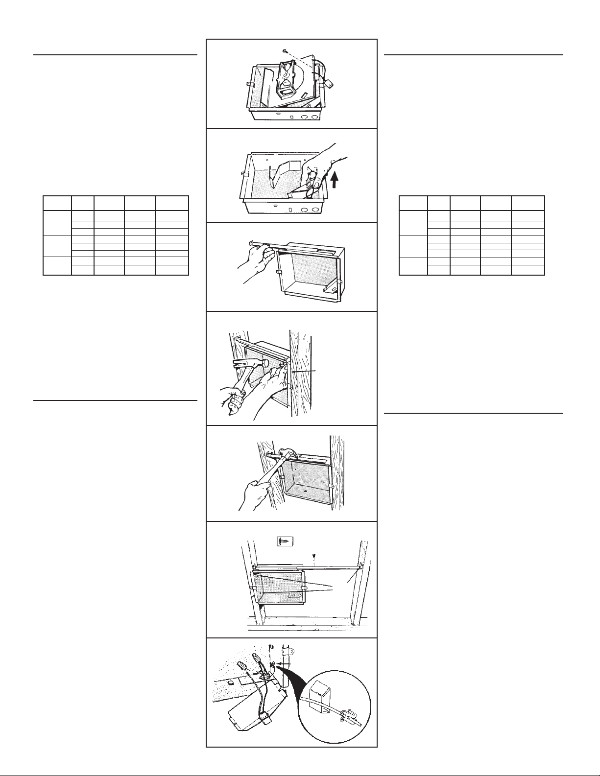
1. Remove the retaining screw, unplug wiring harness
Plan to supply the heater with proper line voltage
and lift heater assembly from housing. (FIG. 2)
and appropriate power cable.
2. Slide the wiring cover out of housing. (FIG. 3)
NOTE: Power can be tapped from a nearby circuit
depending on the heater wattage required and
the amperage rating of the circuit.
INSTALLATION
Heater can be converted to half-wattage to avoid
WARNING: To reduce the risk of fire, do not store or
overloading such circuits.
use gasoline or other flammable vapors and liquids
in the vicinity of the heater.
The table below lists the ratings for each model.
CAUTION: High temperature, risk of fire, keep
electrical cords, drapery, furnishings, and other
MODELS
VOLTS
AMPS
4.16
3.61
6.25
5.41
WATTS
1000/500
1500 /750
2000/1000
1500/750
combustibles at least 3 feet (0.9 m) from the front of
the heater and away from the side and rear.
(16"-ON-CENTER STUDS ONLY)
NOTE: Locate housing at least 6" from the floor and
any adjacent walls.
1. Choose which side of housing will be mounted di-
rectly to a wall stud. Then insert a mounting bracket
from the opposite side into the channel at the top
of the housing. (FIG. 4)
2. Use measuring guide on side of housing to posi-
BOLD ratings are factory wired. See "OPTIONAL
tion housing so that it will be flush with finished
WIRING CONVERSION" section for wattage and
wall. Drive to (2) nails through the holes on side of
voltage conversion instructions.
housing and into stud. (FIG. 5)
3. Extend mounting bracket, level housing, and nail
Follow these basic steps when installing this
to other stud. (FIG. 6)
heater.
(24"-ON-CENTER STUDS ONLY)
• Nail housing to studs.
1. Choose which side of housing will be mounted di-
rectly to a wall stud. From this side, push a mounting
• Connect power cable.
bracket as far as possible into the channel at the
• Fasten heater assembly and grille to
top of the housing.
housing. (FIG. 1)
NOTE: Locate housing at least 6" from the floor
and any adjacent walls.
2. Use measuring guide on side of housing to posi-
tion housing so that it will be flush with finished
PREPARATION
wall. Drive two (2) nails through the holes in side
1. Remove the retaining screw, unplug wiring
of housing and into stud. (FIG. 7)
har ness and lift heater assembly from housing.
3. Secure the two (2) mounting brackets together (with
screw supplied). Level housing and nail to opposite
(FIG. 2)
stud, as shown.
2. Slide the wiring cover out of housing. (FIG.
120
124
128
120
240
208
120
240
208
240
208
8.33/4.16
12.5/6.25
6.33/4.16
7.21/3.61
1000
750
1500
112 5
BTU/HR
3413/1707
3413
2560
5120/2560
5120
3840
6827/3413
5120/2560
3)
WIRING
(ALL INSTALLATIONS)
1. Feed electrical power cable through open knockout
in corner of housing and attach with appropriate
connector. Allow 6" of wire inside of housing.
NOTE: Use other housing knockout when wiring
units in parallel. (FIG. 8)
2. Connect black to black, white to white. Use ground-
ing clip to attach green or bare wire to housing.
Replace wiring cover. (FIG. 9)
OPTIONAL WIRING
CONVERSIONS
(FIGS. 10, 11, 12)
1. Conversion to half-wattage. (FIG. 10)
The heater will produce less heat and use less
electricity if converted to half-wattage.
Disconnect ONE of the two (2) black wires (with
insulated terminals) from the motor.
2. 120 VAC to 240 VAC Conversion (FIGS. 11 &
12)
(Factory-wired 120 VAC Models 120 and 124 ONLY)
These heaters can be converted to operate on
240 VAC.
1) Disconnect ONE of the two (2) black wires (with
insulated terminals) from the motor.
2) Disconnect the two (2) white wires (with insulated
terminals) from each other. Do not remove the
white wire from beneath plastic wire tie.
3) Connect the black wire to the white wire.
NOTE: When heater is converted from 120 VAC to
240 VAC, half-wattage conversion is not possible.
FIG. 2
FIG. 3
FIG. 4
FIG. 5
FIG. 6
FIG. 7
MEASURING
GUIDES/
GUIAS DE
MEDIDA
FIG. 8
MEASURING
GUIDE/GUIA
DE MEDIDA
NAIL
HERE/
CLAVE
AQUI
GROUNDING CLIP/
SUJETADOR PARA
CONEXION A TIERRA
2
La tabla abajo demuestra el grado para cada modelo.
PLANIFICACION
Al instalar este calentador, siga estos pasos básicos:
• Clave la caja en las vigas.
Este calentador ha sido diseñado para proporcionar
• Conecte el cable de potencia.
calefacción adicional desde una pared en una con-
• Fije el conjunto del calentador y la rejilla a la caja.
strucción nueva o una ya existente.
(FIG. 1)
El calentador se puede poner en funcionamiento
desde una pared usando el termostato de tensión
PREPARACION
de línea Broan Modelo 86W. Adquiera los controles
1. Saque el tornillo de retención, desenchufe el conjunto
en forma separada.
de cables preconfigurado y saque de la caja el conjunto
Planifique proporcionar al calentador la tensión de
del calentador. (FIG. 2)
línea y cable de energía eléctrica apropiados.
2. Saque la cubierta de la caja. (FIG. 3)
NOTA: La energía se puede tomar de un circuito
cercano, lo que dependerá del vatiaje requerido del
INSTALACION
calentador y amperaje nominal del circuito.
ADVERTENCIA: Para reducir el riesgo de incendio, no
El calentador se puede convertir a mitad de vatiaje
almacene ni use gasolina u otros vapores y líquidos
para evitar sobrecargar dichos circuitos.
flamables en las cercanías del calentador.
PRECAUCIÓN: Temperatura alta, el riesgo de incendio,
MODELOS
VOLTIOS
AMPS
4.16
3.61
6.25
5.41
VATIOS
1000/500
1500 /750
2000/1000
1500/750
mantenga los cables eléctricos, cortinas, muebles y
otros materiales combustibles por lo menos 3 pies
(0,9 m) del frente del calentador y lejos de la cara y la
parte trasera.
(VIGAS DE 40,64 CM DE CENTRO SOLAMENTE)
NOTA: sitúe la caja a no menos de 15,24 cm (6 pulg.) del
piso o cualquier pared adyacente.
1. Elija cuál lado de la caja se va a montar directamente
a una viga de la pared. Después, meta un soporte de
montaje, desde el lado opuesto, dentro del canal en la
parte superior de la caja. (FIG. 4)
El cableado viene de fábrica para las corrientes nomi-
2. Use la guía de medida que está en el lado de la caja
nales en letras oscuras. Sección “CONVERSIONES
para colocar ésta a nivel con la pared terminada. Pase
DE CABLEADO ORIGINAL” encontrará las instruc-
dos (2) clavos por los agujeros en el costado de la caja
y clávelos en la viga de la pared. (FIG. 5)
ciones de vatiaje y conversión de tensión.
3. Extienda los soportes de montaje, nivele la caja, y clave
a la otra viga. (FIG. 6)
La tabla abajo demuestra el grado para cada modelo.
(VIGAS DE 60,96 CM (24 PULG.) DE CENTRO)
Al instalar este calentador, siga estos pasos básicos:
1. Elija cuál lado de la caja se va a montar directamente
• Clave la caja en las vigas.
a la viga de la pared. Desde este lado, meta un soporte
de montaje hasta lo más profundo que se pueda dentro
• Conecte el cable de potencia.
del canal en la parte superior de la caja.
• Fije el conjunto del calentador y la rejilla a la caja.
NOTA: sitúe la caja cuando menos 15,24 cm (6 pulg.)
(FIG. 1)
del piso y cualquier pared cercana.
2. Use la guía de medida que está en un costado de la caja
para colocar ésta para que quede a nivel con la pared
terminada. Pase dos (2) clavos por los agujeros en el
PREPARACION
lado de la caja y clávelos en la viga de la pared. (FIG. 7)
1. Saque el tornillo de retención, desenchufe el
3. Fije los dos (2) soportes de montaje juntos (con el tornillo
que se incluye). Nivele la caja y clávela a la viga opuesta,
conjunto de cables preconfigurado y saque de
tal como se muestra.
la caja el conjunto del calentador. (FIG. 2)
2. Saque la cubierta de la caja. (FIG. 3)
CABLEANDO
(TODAS LAS INSTALACIONES)
1. Traiga el cable de energía eléctrica por la abertura del
disco removible en una esquina de la caja y fije con el
conector apropiado. Deje 15,24 cm (6 pulg.) de cable
dentro de la caja.
NOTA: use otro disco removible cuando cablee unidades
en paralelo. (FIG. 8)
2. Conecte negro a negro, blanco a blanco. Use el sujetador
para conexión a tierra para fijar el alambre verde o
descubierto a la caja. Coloque de nuevo la cubierta de
cableado. (FIG. 9)
120
124
128
120
240
208
120
240
208
240
208
8.33/4.16
12.5/6.25
6.33/4.16
7.21/3.61
1000
750
1500
112 5
BTU/HR
3413/1707
3413
2560
5120/2560
5120
3840
6827/3413
5120/2560
CONVERSIONES DE
CABLEADO OPCIO-
NALES (FIGS. 10, 11, 12)
1. Conversión a medio vatiaje (FIG. 10)
El calentador produce menos calor y usa menos
electricidad si se convierte a medio vatiaje.
Desconecte del motor UNO de los dos (2) cables negros
(que tienen terminals aisladas).
2. Conversión de 120 VCA a 240 VCA (FIGS. 11 y 12)
(Solamente modelos 120 y 124 cableados de fábrica
para 120 VCA).
Estos calentadores de pueden convertir para que
funcionen en 240 VCA.
1) Desconecte del motor UNO de los dos (2) cables negros
(que tienen terminal aislada).
2) Desconecte los dos (2) cables blancos (con terminales
aisladas). No saque el cable blanco debajo del enlace
de cable plástico.
3) Conecte el cable negro al cable blanco.
NOTA: cuando el calentador se convierte de 120 VCA
a 240 VCA, no es posible convertir a medio vatiaje.
Page 3

INSTALLATION
WARNING: To reduce the risk of fire, do not store or
use gasoline or other flammable vapors and liquids
in the vicinity of the heater.
CAUTION: High temperature, risk of fire, keep
electrical cords, drapery, furnishings, and other
combustibles at least 3 feet (0.9 m) from the front of
the heater and away from the side and rear.
(16"-ON-CENTER STUDS ONLY)
NOTE: Locate housing at least 6" from the floor and
any adjacent walls.
1. Choose which side of housing will be mounted directly to a wall stud. Then insert a mounting bracket
from the opposite side into the channel at the top
of the housing. (FIG. 4)
2. Use measuring guide on side of housing to position housing so that it will be flush with finished
wall. Drive to (2) nails through the holes on side of
housing and into stud. (FIG. 5)
3. Extend mounting bracket, level housing, and nail
to other stud. (FIG. 6)
(24"-ON-CENTER STUDS ONLY)
1. Choose which side of housing will be mounted
directly to a wall stud. From this side, push a mounting bracket as far as possible into the channel at
the top of the housing.
NOTE: Locate housing at least 6" from the floor
and any adjacent walls.
2. Use measuring guide on side of housing to position housing so that it will be flush with finished
wall. Drive two (2) nails through the holes in side
of housing and into stud. (FIG. 7)
3. Secure the two (2) mounting brackets together (with
screw supplied). Level housing and nail to opposite
stud, as shown.
WIRING
(ALL INSTALLATIONS)
1. Feed electrical power cable through open knockout
in corner of housing and attach with appropriate
connector. Allow 6" of wire inside of housing.
NOTE: Use other housing knockout when wiring
units in parallel. (FIG. 8)
2. Connect black to black, white to white. Use grounding clip to attach green or bare wire to housing.
Replace wiring cover. (FIG. 9)
FIG. 9
DISCONNECT FOR HALF-
WAT TAGE
BLACK
NEGRO
HEATING
ELEMENT
ELEMENTO
DE CALOR
FACTORY-WIRED
HEATER
(FULL WATTAGE)
CALENTADOR
CABLEADO DE
FABRICA (VATIAJE
COMPLETO)
WHITE
BLANCO
DESCONECTE PARA MEDIO
VATIAJE
BLACK
BLACK
NEGRO
NEGRO
M
WHITE
WHITE
LINE IN LINEA DE ENTRADA
BLACK
BLANCO
BLACK
BLANCO
THERMAL
OVERLOAD
SOBRECARGA
TERMICA
NEGRO
NEGRO
BLACK
NEGRO
FIG. 10 - HALF-WATTAGE CONVERSION
CONVERSIÓN DE MEDIO VATIAJE
(2) BLACK WIRES (connected to motor)
(2) CABLES NEGROS (conectados al motor)
MOTOR
FIG. 11 - 120VAC TO 240VAC CONVERSION
CONVERSIÓN DE 120VCA A 240VCA
WHITE WIRES
CABLES BLANCOS
BLACK WIRE (from motor)
CABLE NEGRO (del motor)
MOTOR
INSTALACION
ADVERTENCIA: Para reducir el riesgo de incendio, no
almacene ni use gasolina u otros vapores y líquidos
flamables en las cercanías del calentador.
PRECAUCIÓN: Temperatura alta, el riesgo de incendio,
mantenga los cables eléctricos, cortinas, muebles y otros
materiales combustibles por lo menos 3 pies (0,9 m) del
frente del calentador y lejos de la cara y la parte trasera.
(VIGAS DE 40,64 CM DE CENTRO SOLAMENTE)
NOTA: sitúe la caja a no menos de 15,24 cm (6 pulg.) del
piso o cualquier pared adyacente.
1. Elija cuál lado de la caja se va a montar directamente
a una viga de la pared. Después, meta un soporte de
montaje, desde el lado opuesto, dentro del canal en la
parte superior de la caja. (FIG. 4)
2. Use la guía de medida que está en el lado de la caja
para colocar ésta a nivel con la pared terminada. Pase
dos (2) clavos por los agujeros en el costado de la caja
y clávelos en la viga de la pared. (FIG. 5)
3. Extienda los soportes de montaje, nivele la caja, y clave
a la otra viga. (FIG. 6)
(VIGAS DE 60,96 CM (24 PULG.) DE CENTRO)
1. Elija cuál lado de la caja se va a montar directamente
a la viga de la pared. Desde este lado, meta un soporte
de montaje hasta lo más profundo que se pueda dentro
del canal en la parte superior de la caja.
NOTA: sitúe la caja cuando menos 15,24 cm (6 pulg.)
del piso y cualquier pared cercana.
2. Use la guía de medida que está en un costado de la caja
para colocar ésta para que quede a nivel con la pared
terminada. Pase dos (2) clavos por los agujeros en el lado
de la caja y clávelos en la viga de la pared. (FIG. 7)
3. Fije los dos (2) soportes de montaje juntos (con el tornillo
que se incluye). Nivele la caja y clávela a la viga opuesta,
tal como se muestra.
CABLEANDO
(TODAS LAS INSTALACIONES)
1. Traiga el cable de energía eléctrica por la abertura del
disco removible en una esquina de la caja y fije con el
conector apropiado. Deje 15,24 cm (6 pulg.) de cable
dentro de la caja.
NOTA: use otro disco removible cuando cablee unidades
en paralelo. (FIG. 8)
2. Conecte negro a negro, blanco a blanco. Use el sujetador
para conexión a tierra para fijar el alambre verde o
descubierto a la caja. Coloque de nuevo la cubierta de
cableado. (FIG. 9)
OPTIONAL WIRING
CONVERSIONS
(FIGS. 10, 11, 12)
1. Conversion to half-wattage. (FIG. 10)
The heater will produce less heat and use less
electricity if converted to half-wattage.
Disconnect ONE of the two (2) black wires (with
insulated terminals) from the motor.
2. 120 VAC to 240 VAC Conversion (FIGS. 11 &
12)
(Factory-wired 120 VAC Models 120 and 124 ONLY)
These heaters can be converted to operate on
240 VAC.
1) Disconnect ONE of the two (2) black wires (with
insulated terminals) from the motor.
2) Disconnect the two (2) white wires (with insulated terminals) from each other. Do not remove
the white wire from beneath plastic wire tie.
3) Connect the black wire to the white wire.
NOTE: When heater is converted from 120 VAC to
240 VAC, half-wattage conversion is not possible.
FIG. 12
BLACK
NEGRO
HEATING
ELEMENT
WHITE
ELEMENTO
BLANCO
DE CALOR
WHITE
BLANCO
WHITE
BLANCO
CONVERTED 240 VAC HEATER
CALENTADOR CONVERTIDO
240 VCA
BLACK
BLACK
NEGRO
NEGRO
THERMAL
OVERLOAD
SOBRECARGA
BLACK
BLANCO
BLACK
BLANCO
TERMICA
NEGRO
NEGRO
M
WHITE
WHITE
LINE IN LINEA DE ENTRADA 240VCA
CONVERSIONES DE
CABLEADO OPCIONALES (FIGS. 10, 11, 12)
1. Conversión a medio vatiaje (FIG. 10)
El calentador produce menos calor y usa menos
electricidad si se convierte a medio vatiaje.
Desconecte del motor UNO de los dos (2) cables negros
(que tienen terminals aisladas).
2. Conversión de 120 VCA a 240 VCA (FIGS. 11 y 12)
(Solamente modelos 120 y 124 cableados de fábrica
para 120 VCA).
BLACK
NEGRO
Estos calentadores de pueden convertir para que
funcionen en 240 VCA.
1) Desconecte del motor UNO de los dos (2) cables negros
(que tienen terminal aislada).
2) Desconecte los dos (2) cables blancos (con terminales
aisladas). No saque el cable blanco debajo del enlace
de cable plástico.
3) Conecte el cable negro al cable blanco.
NOTA: cuando el calentador se convierte de 120 VCA a
240 VCA, no es posible convertir a medio vatiaje.
3
Page 4

COMPLETE
FIG. 13
COMPLETANDO LA
THE INSTALLATION
(NEW CONSTRUCTION)
1. A housing mask has been provided to keep
construction dust, drywall spray, paint, etc. from
damaging heater.
Bend the flaps on the mask and push it into the
heater housing.
NOTE: Mask can be put in place before or after
heater assembly is reinstalled.
2. Remove mask before operation.
(ALL INSTALLATIONS)
3. Secure heater assembly with retaining screw and
plug wiring harness into receptacle.
4. Fasten grille to heater with two (2) screws provided.
(FIG. 13)
5. Turn on power at service entrance. Turn thermostat
to its highest setting and make sure heating element
and blower come on. Then turn it to its lowest setting
and make sure element and blower shut off.
INSTALACION
(CONSTRUCCIONES NUEVAS)
1. Una cubierta de caja se incluye para evitar que el
polvo de construcción, rocíos de yeso, pintura, etc.
dañen el calentador.
Doble las aletas en la cubierta y empújela dentro de
la caja del calentador.
NOTA: la cubierta se puede poner en su lugar antes
o después de reinstalar el conjunto del ventilador.
2. Quite la cubierta antes de la operación.
(TODAS LAS INSTALACIONES)
3. Fije el conjunto del calentador con el tornillo
de retención y enchufe el conjunto de cables
preconfigurado al enchufe.
4. Fije la rejilla al calentador con dos (2) tornillos que se
incluyen.
5. Conecte la potencia en la entrada de servicio. Ponga
el termostato en su graduación más alta y compruebe
que el elemento de calor y el soplador se enciendan.
Póngalo después en su graduación más baja y
compruebe que el elemento y el soplador se apaguen.
4
Page 5

OPERATION
Before using heater, make sure heater has been properly
installed according to installation steps beginning with the
"PLANNING" section on page 1.
OPERACIÓN
Antes de usar el calentador, asegúrese de que esté
instalado adecuadamente, de acuerdo con los pasos de
instalación indicados en “INSTALACIÓN” en la página 1.
5
Page 6

MAINTENANCE
The following maintenance and cleaning tasks
can be performed by the user. All other servicing
must be performed by an authorized technician If
you have any questions, please consult with our
customer service department at: 800-558-1711.
THERMAL OVERLOAD PROTECTOR
If heater fails to operate when thermostat is turned
to its highest setting: Turn power off at service entrance. Remove knob and grille and press button
marked “RESET”.
LUBRICATION
The heater is permanently lubricated and never
needs oiling or disassembly.
CLEANING
Clean heater once a month as follows:
1. Turn off power at service panel.
2. Make sure heating element is cool.
3. Use a soft brush attachment to gently vacuum
grille openings or wipe grille clean with a soft
cloth.
4. Restore power.
CAUTION: METAL AND ELECTRICAL PARTS
SHOULD NEVER BE IMMERSED IN WATER.
MANTENIMIENTO
El usuario puede realizar las siguientes tareas de
mantenimiento y limpieza. Todos los demás servicios los debe realizar un técnico autorizado. Si
tiene preguntas, consulte a nuestro departamento
de servicio al cliente llamando al: 800-558- 1711.
PROTECTOR DE SOBRECARGA TERMICA
Si el calentador no funciona cuando el termostato
está prendido en su graduación más alta, desconecte la potencia en la entrada de servicio. Quite
la perilla y la rejilla y oprima el botón marcado
“RESET”.
LUBRICACIÓN
El calentador está permanentemente lubricado
y nunca necesitará ponerle aceite ni desarmarlo.
LIMPIEZA
Limpie el calentador una vez al mes tal como sigue:
1. Apague la energía eléctrica en el panel de servicio.
2. Asegúrese de que el elemento de calefacción
esté frío.
3. Use un aditamento de cepillo suave para aspirar
suavemente aberturas de la rejilla o limpie la
rejilla con un paño suave.
4. Restaure la energía eléctrica.
CUIDADO: LAS PIEZAS METALICAS Y ELECTRICAS NUNCA SE DEBEN SUMERGIR EN AGUA.
6
Page 7

WARRANTY GARANTIA
BROAN-NUTONE ONE YEAR LIMITED WARRANTY
Broan-NuTone warrants to the original consumer purchaser of its
products that such products will be free from defects in materials
or workmanship for a period of one year from the date of original
purchase. THERE ARE NO OTHER WARRANTIES, EXPRESS OR IMPLIED, INCLUDING, BUT NOT LIMITED TO, IMPLIED WARRANTIES
OF MERCHANTABILITY OR FITNESS FOR A PARTICULAR PURPOSE.
During this one-year period, Broan-NuTone will, at its option, repair
or replace, without charge, any product or part which is found to be
defective under normal use and service.
THIS WARRANTY DOES NOT EXTEND TO FLUORESCENT LAMP
STARTERS, TUBES, HALOGEN AND INCANDESCENT BULBS, FUSES,
FILTERS, DUCTS, ROOF CAPS, WALL CAPS AND OTHER ACCESSORIES FOR DUCTING. This warranty does not cover (a) normal maintenance and service or (b) any products or parts which have been
subject to misuse, negligence, accident, improper maintenance or
repair (other than by Broan-NuTone), faulty installation or installation
contrary to recommended installation instructions.
The duration of any implied warranty is limited to the one-year period
as specified for the express warranty. Some states do not allow limitation on how long an implied warranty lasts, so the above limitation
may not apply to you.
BROAN-NUTONE’S OBLIGATION TO REPAIR OR REPLACE, AT
BROAN-NUTONE’S OPTION, SHALL BE THE PURCHASER’S SOLE
AND EXCLUSIVE REMEDY UNDER THIS WARRANTY. BROAN-NUTONE SHALL NOT BE LIABLE FOR INCIDENTAL, CONSEQUENTIAL
OR SPECIAL DAMAGES ARISING OUT OF OR IN CONNECTION WITH
PRODUCT USE OR PERFORMANCE. Some states do not allow the
exclusion or limitation of incidental or consequential damages, so the
above limitation or exclusion may not apply to you.
This warranty gives you specific legal rights, and you may also have
other rights, which vary from state to state. This warranty supersedes
all prior warranties.
To qualify for warranty service, you must (a) notify Broan-NuTone at
the address or telephone number below, (b) give the model number
and part identification and (c) describe the nature of any defect in the
product or part. At the time of requesting warranty service, you must
present evidence of the original purchase date.
Broan-NuTone LLC
926 W. State Street, Hartford, Wisconsin 53027
www.broan.com 800-558-1711
GARANTIA BROAN-NUTONE LIMITADA POR UN AÑO
Broan-NuTone garantiza al consumidor comprador original de sus
productos que dichos productos carecerán de defectos en materiales o
en mano de obra por un período de un año a partir de la fecha original de
compra. NO EXISTEN OTRAS GARANTIAS, EXPLICITAS O IMPLICITAS,
INCLUYENDO, PERO NO LIMITADAS A, GARANTIAS IMPLICITAS DE
COMERCIALIZACION O APTITUD PARA UN PROPOSITO PARTICULAR.
Durante el período de un año, y a su propio criterio, Broan-NuTone
reparará o reemplazará, sin costo alguno cualquier producto o pieza que
se encuentre defectuosa bajo condiciones normales de servicio y uso.
LA PRESENTE GARANTÍA NO CUBRE LOS TUBOS FLUORESCENTES
NI SUS ARRANCADORES, BOMBILLAS DE HALÓGENO E INCANDESCENTES, FUSIBLES, FILTROS, CONDUCTOS, TAPONES DE TECHO O
PAREDES Y DEMÁS ACCESORIOS PARA CONDUCTOS. Esta garantía no
cubre (a) mantenimiento y servicio normales o (b) cualquier producto
o piezas que hayan sido utilizadas de forma errónea, negligente, que
hayan causado un accidente, o que hayan sido reparadas o mantenidas
inapropiadamente (por otras compañías que no sean Broan-NuTone),
instalación defectuosa, o instalación contraria a las instrucciones de
instalación recomendadas.
La duración de cualquier garantía implícita se limita a un período de
un año como se especifica en la garantía expresa. Algunos estados
no permiten limitaciones en cuanto al tiempo de expiración de una
garantía implícita, por lo que la limitación antes mencionada puede no
aplicarse a usted.
LA OBLIGACION DE BROAN-NUTONE DE REPARAR O REEMPLAZAR,
SIGUIENDO EL CRITERIO DE BROAN-NUTONE, DEBERA SER EL UNICO
Y EXCLUSIVO RECURSO LEGAL DEL COMPRADOR BAJO ESTA GARANTIA. BROAN-NUTONE NO SERA RESPONSABLE POR DAÑOS INCIDENTALES, CONSIGUIENTES, O POR DAÑOS ESPECIALES QUE SURJAN A
RAIZ DEL USO O DESEMPEÑO DEL PRODUCTO. Algunos estados no
permiten la exclusión o limitación de daños incidentales o consiguientes,
por lo que la limitación antes mencionada puede no aplicarse a usted.
Esta garantía le proporciona derechos legales específicos, y usted puede
también tener otros derechos, los cuales varían de estado a estado. Esta
garantía reemplaza todas las garantías anteriores.
Para calificar en la garantía de servicio, usted debe (a) notificar a BroanNuTone al domicilio o al número de teléfono que se menciona abajo, (b)
dar el número del modelo y la identificación de la pieza, y (c) describir la
naturaleza de cualquier defecto en el producto o pieza. En el momento
de solicitar servicio cubierto por la garantía, usted debe de presentar
evidencia de la fecha original de compra.
Broan-NuTone LLC
926 W. State Street, Hartford, Wisconsin 53027
www.broan.com 800-558-1711
7
Page 8

SERVICE PARTS
MODELS 120, 124 & 128
PIEZAS DE SERVICIO
MODELOS 120, 124 y128
KEY NO.
NUMERO
DE CODIGO
1
2
3
4
5
6
7
8
9
10
11
12
13
14
15
16
17
18
19
20
21
22
23
24
**
*Standard hardware - may be purchased locally. *Herrajes estandar - pueder comprarse localmente.
**Not shown. **No ilustrad.
Always order replacement parts by"PART NO."— NOT by "KEY NO."
Encargue siempre piezas de reemplazo por NÚMERO DE PIEZA, y NO por NÚMERO DE CÓDIGO.
PART NO.
NUMERO
DE PIEZAS
97008853
98003036
*
99390015
97005422
98006975
99020130
99080248
99080252
99270735
99030194
99271091
98006974
99150491
99270741
99270725
99270742
93270619
97008682
99260428
97008856
97008678
*
97013821
*
93270493
99140470
97008724
DESCRIPTION
Housing
Mounting Bracket (2 Required)
#8–18 Sheet Metal Nut (2 Required)
Grounding Clip
Receptacle Assembly
Wiring Cover
Blower Wheel
Motor (Models 120 and 124)
Motor (Model 128)
Tab Adaptor
Thermal Overload
Guard
Element Bracket
Screw, #8–18 x 3/8 Ph. Pan Head (5 Required)
Heating Element (Model 120)
Heating Element (Model 124)
Heating Element (Model 128)
Wire Clamp
Partition Plate Assembly
Nut, #6–32 x 5/16 Keps (2 Required)
Plug Assembly
Overload Wire Assembly
Screw, #8–18 x 5/8 Ph. Pan Head
Grille (Includes Parts Bag**)
Grille Screw (2 Required)
Wire Tie
Screw, #8–18 x 3/8 Ph. Truss Head
Parts Bag (contains Key Nos. 3, 20 & 21)
DESCRIPCION
Caja
Soporte de montaje (se requieren 2)
Tuerca de lámina de metal #8-18 (se requieren 2)
Fijador de conexión a tierra
Conjunto de enchufe
Cubierta de cableado
Rueda del soplador
Motor (Modelos 120 y 124)
Motor (Modelo 128)
Adaptador de lengüeta
Sobrecarga térmica
Protector
Elemento de soporte
Tornillo phillips, #8-18 x 3/8 cabeza grande (se requieren 5)
Elemento de calor (Modelo 120)
Elemento de calor (Modelo 124)
Elemento de calor (Modelo 128)
Sujetador de cable
Conjunto de placa separadora
Tuerca, keps #6-32 x 5/16 (se requieren 2)
Conjunto de enchufe
Conjunto del cable de sobrecarga
Tornillo, #8-18 x 5/8 cabeza grande
Rejilla (incluye Bolsa de piezas **)
Tornillo de rejilla (Se requieren 2)
Lazo de cable
Tornillo phillips de enlace #8-18 x 3/8
Bolsa de piezas (incluye Numeros de codigos 3, 20, y 21)
99045028B
8
 Loading...