


WWW.BROAN.COM
WWW.BROAN.CA
RANGE HOOD
Series: ALT1 and ALT2
INSTALLATION, USE
AND CARE MANUAL
Serial number:
99046182A

Safety . . . . . . . . . . . . . . . . . . . . . . . . . . . . . . . . . 3-4
Operation . . . . . . . . . . . . . . . . . . . . . . . . . . . . . . . 5
Cleaning and Maintenance . . . . . . . . . . . . . . . . . 6
Motor
Grease Filters
Non-Ducted Recirculation Filters
Fan Blade
Stainless Steel Cleaning
Painted Finish Cleaning
Installation . . . . . . . . . . . . . . . . . . . . . . . . . . . . 7-20
Recommended Tools
and Accessories for Installation . . . . . . . . . . . . 7
Install Ductwork (Ducted Installations Only) . . . 7
Contents . . . . . . . . . . . . . . . . . . . . . . . . . . . . . . 8
Prepare the Hood . . . . . . . . . . . . . . . . . . . . . . . 9-11
Prepare the Hood Location . . . . . . . . . . . . . . . . 12
EZ1 one-person Installation . . . . . . . . . . . . . . 12-14
Install the Hood (EZ1 Bracket) . . . . . . . . . . . . 15-16
Standard Installation . . . . . . . . . . . . . . . . . . . 17
Install the Hood (Standard Installation) . . . . . 18
Connect the Wiring . . . . . . . . . . . . . . . . . . . . . . 19
Light Bulbs (ALT1 Series only) . . . . . . . . . . . . . 20
Install the Filters . . . . . . . . . . . . . . . . . . . . . . . . 20
Wiring Diagrams . . . . . . . . . . . . . . . . . . . . . . . . 21
Service Parts . . . . . . . . . . . . . . . . . . . . . . . . . 22-23
Warranty . . . . . . . . . . . . . . . . . . . . . . . . . . . . . . . 24
INSTALLATION MANUAL
TABLE OF CONTENTS
2
READ AND SAVE THESE INSTRUCTIONS
!
Intended for domestic cooking only
!
INSTALLER: LEAVE THIS MANUAL WITH HOMEOWNER.
In U.S.A., register your range hood online at www.broan.com
In Canada, register your range hood online at www.broan.ca
!
WARNING
TO REDUCE THE RISK OF FIRE, ELECTRIC SHOCK, OR INJURY TO
PERSONS, OBSERVE THE FOLLOWING:
• Use this unit only in the manner intended by the manufacturer. If you have
questions, contact the manufacturer at the address or telephone number
listed in the warranty.
• Before servicing or cleaning unit, switch power off at service panel and
lock the service disconnecting means to prevent power from being
switched on accidentally. When the service disconnecting means cannot
be locked, securely fasten a prominent warning device, such as a tag, to
the service panel.
• Installation work and electrical wiring must be done by a qualified
person(s) in accordance with all applicable codes and standards, including
fire-rated construction.
• Sufficient air is needed for proper combustion and exhausting of
gases through the flue (chimney) of fuel burning equipment to prevent
backdrafting. Follow the heating equipment manufacturer’s guidelines and
safety standards such as those published by the National Fire Protection
Association (NFPA) and the American Society for Heating, Refrigeration
and Air Conditioning Engineers (ASHRAE) and the local code authorities.
• When cutting or drilling into wall or ceiling, do not
damage electrical wiring and other hidden utilities.
• Ducted fans must always be vented to the outdoors.
• Do not use this unit with any additional solid-state speed control device.
• To reduce the risk of fire, use only metal ductwork.
• This unit must be grounded.
• As an alternative, this product may be installed with the UL-approved cord
kit designated for the product, following instructions packed with the cord
kit.
• When applicable local regulations comprise more restrictive installation
and/or certification requirements, the aforementioned requirements prevail
on those of this document and the installer agrees to conform to these at
his own expense.
INSTALLATION MANUAL
SAFETY
3
!
WARNING
TO REDUCE THE RISK OF A RANGE TOP GREASE FIRE:
a) Never leave surface units unattended at high settings. Boilovers cause
smoking and greasy spillovers that may ignite. Heat oils slowly on low or
medium settings.
b) Always turn hood ON when cooking at high heat or when flambeing food
(i.e.: Crêpes Suzette, Cherries Jubilee, Peppercorn Beef Flambé).
c) Clean ventilating fan frequently. Grease should not be allowed to
accumulate on fan, filters or in exhaust ducts.
d) Use proper pan size. Always use cookware appropriate for the size of
the surface element.
TO REDUCE THE RISK OF INJURY TO PERSONS IN THE EVENT OF A
RANGE TOP GREASE FIRE, OBSERVE THE FOLLOWING*:
1. SMOTHER FLAMES with a close-fitting lid, cookie sheet or metal tray,
then turn off the burner. BE CAREFUL TO PREVENT BURNS. IF THE
FLAMES DO NOT GO OUT IMMEDIATELY, EVACUATE AND CALL
THE FIRE DEPARTMENT.
2. NEVER PICK UP A FLAMING PAN — You may be burned.
3. DO NOT USE WATER, including wet dishcloths or towels — This could
cause a violent steam explosion.
4. Use an extinguisher ONLY if:
A. You own a Class ABC extinguisher and you know how to operate it.
B. The fire is small and contained in the area where it started.
C. The fire department has been called.
D. You can fight the fire with your back to an exit.
* Based on “Kitchen Fire Safety Tips” published by NFPA.
INSTALLATION MANUAL
SAFETY
4
!
CAUTION
• For indoor use only.
• For general ventilating use only. Do not use to exhaust hazardous or explosive materials
and vapors.
• To avoid motor bearing damage and noisy and/or unbalanced fan blade, keep drywall
spray, construction dust, etc. off range hood.
• Your hood motor has a thermal overload which will automatically shut off the motor if it
becomes overheated. The motor will restart when it cools down. If the motor continues to
shut off and restart, have the hood serviced.
• For best capture of cooking fumes, the bottom of the hood MUST NOT BE LESS than 18”
and at a maximum of 24” above the cooking surface.
• Always follow the cooking equipment manufacturer’s requirements regarding the ventilation
needs.
• To reduce the risk of fire and to properly exhaust air, be sure to duct air outside — Do not
exhaust air into spaces within walls or ceiling or into attics, crawl space or garage.
• When installing, servicing or cleaning the unit, it is recommended to wear safety glasses
and gloves.
• Please read specification label on product for further information and requirements.
Operation
Always turn your hood on before you begin cooking to establish an air flow in the kitchen.
Let the blower run for a few minutes to clear the air after you turn off the range. This will help
keep the whole kitchen cleaner and fresher. Operate the hood as follows:
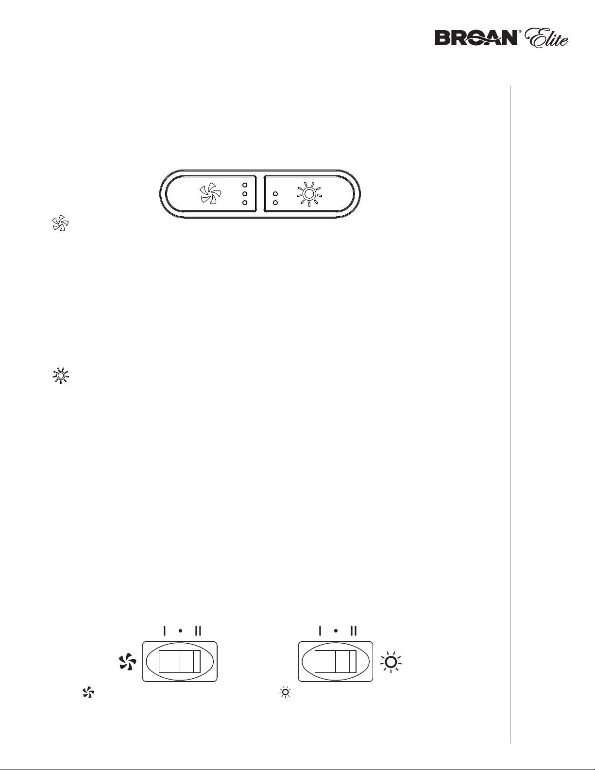
ALT2 SERIES
BLOWER BUTTON
When blower is OFF, press this button to turn ON the blower at the last saved speed. If there was
no speed saved, the blower will be set on LOW speed.
NOTE: When LOW speed is activated from OFF, the blower starts on MEDIUM speed for a very
short lapse of time, and then resume to LOW speed.
To change the blower speed, press on this button again until the desired speed is reached (from
LOW to MEDIUM to HIGH speed to OFF). Each time a blower speed is activated, a beep is heard
and LED indicators light up to show the corresponding speed chosen (lower LED for LOW speed,
lower and center LEDs for MEDIUM speed and all LEDs for HIGH speed).
When blower is on (no matter the speed level), press and hold this button until the beep sound
ends; this will turn off the blower and save this blower speed to memory.
LIGHT BUTTON
When lights are OFF, press once on this button to turn ON the lights at the last saved setting. If
there was no light setting saved, the lights will be set on LOW intensity. Press another time to set
the lights on HIGH intensity. Pressing another time after the HIGH setting will turn OFF the lights.
Each time the lights are turned ON, a beep is heard and LED indicators light up to show the
corresponding intensity chosen (lower LED for LOW and both LEDs for HIGH).
When lights are on (no matter the lighting level), press and hold this button until the beep sound
ends; this will turn off the lights and save the chosen light intensity.
The LED modules included with this hood are the latest in LED cooktop illumination technology
specially designed to operate in the elevated temperatures of cooking - offering bright lighting and
lasting up to 25 times as long as a standard bulb and greater reliability than typical replacement
LED bulbs.
FILTER CLEANING REMINDER
When it is time to clean the hood and filters (refer to Cleaning and Maintenance on page 6), the
3 blower button LED indicators will flash slowly for 30 seconds after turning the blower OFF. This will
happen every time the blower is turned OFF until the filter cleaning reminder has been reset. Once
the cleaning is done, reset the filter cleaning reminder indicators by pressing on blower button for
3 seconds during the 30 seconds the 3 blower button LED indicators flash slowly.
ALT1 SERIES
OPERATION
INSTALLATION MANUAL
BLOWER SWITCH
I Turns blower on to LOW speed.
• Turns blower OFF.
II Turns blower on to HIGH speed.
LIGHT SWITCH
I Turns light on in LOW intensity.
• Turns light OFF.
II Turns light on to HIGH intensity.
5

Cleaning and Maintenance
Proper maintenance of the Range Hood will assure proper performance of the unit.
MOTOR
The motor is permanently lubricated and never need oiling. If the motor bearings make excessive
or unusual noise, replace the motor with the exact service motor. The fan wheel should also be
replaced.
GREASE FILTERS
The grease filters should be cleaned frequently. Use a warm dishwashing detergent solution.
Grease filters are dishwasher safe.
Clean all-metal filters in the dishwasher using a non-phosphate detergent. Discoloration of the
filters may occur if using phosphate detergents, or as a result of local water conditions - but this
will not affect filter performance. This discoloration is not covered by the warranty. To minimize or
prevent discoloration, hand wash filters using a mild detergent.
NON-DUCTED RECIRCULATION FILTERS
The non-ducted recirculation filters should be changed every 3 to 6 months. Replace more often
if your cooking style generates extra grease, such as frying and wok cooking. Refer to installation
instructions included with non-ducted recirculation filters.
FAN BLADE
The fan blade should be cleaned frequently. Use a clean cloth soaked with warm detergent solution.
STAINLESS STEEL CLEANING
Do:
• Regularly wash with clean cloth or rag soaked with warm water and mild soap or liquid dish
detergent.
• Always clean in the direction of original polish lines.
• Always rinse well with clear water (2 or 3 times) after cleaning. Wipe dry completely.
• You may also use a specialized household stainless steel cleaner.
Don’t:
• Use any steel or stainless steel wool or any other scrapers to remove stubborn dirt.
• Use any harsh or abrasive cleansers.
• Allow dirt to accumulate.
• Let plaster dust or any other construction residues reach the hood. During construction/
renovation, cover the range hood to make sure no dust sticks to the stainless steel surface.
Avoid when choosing a detergent:
• Any cleaners that contain bleach will attack stainless steel.
• Any products containing: chloride, fl uoride, iodide, bromide will deteriorate surfaces
rapidly.
• Any combustible products used for cleaning such as acetone, alcohol, ether, benzol, etc.,
are highly explosive and should never be used close to a range.
PAINTED FINISH CLEANING:
INSTALLATION MANUAL
CLEANING AND MAINTENANCE
Clean with warm water and mild detergent only. If discoloration occurs, use a finish polish such
as automotive polish. (DO NOT use rough abrasive cleaner or porcelain cleaner.)
6
For ADA compliance installation guidelines, please visit www.broan.com
Recommended Tools and Accessories
for Installation
• Measuring tape
• Phillips screwdriver no. 2
• Flat blade screwdriver (to open knockout holes)
• Drill, 1/8” drill bit and 1½” hole saw (to mark holes for ducting and cut electrical access hole)
• 7/64” drill bit (to drill holes for EZ1 brackets mounting screws)
• Wood shims (2) and wood screws (4) (required for standard installation to framed cabinet)
• Saw (to cut holes for ducted application)
• Sheet metal shears (ducted installation only, for duct adjustment)
• Pliers (ducted installation only, for duct adjustment)
• Metal foil duct tape (for ducted applications)
• Scissors (to cut metal foil duct tape)
• Pencil
• Wire stripper
• Strain relief, 1/2” diameter (to secure house wiring cable to the hood)
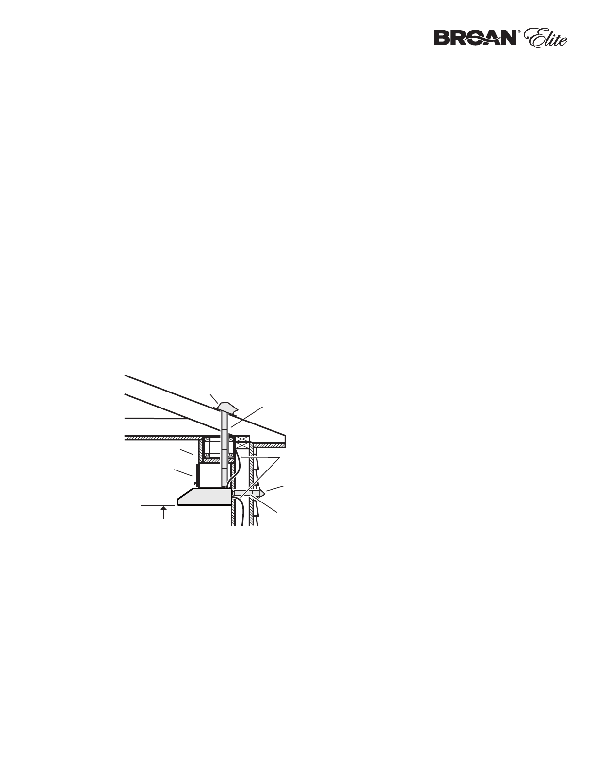
Install Ductwork (Ducted Installations Only)
ROOF CAP
SOFFIT
CABINET
HOOD
18" MIN - 24" MAX
ABOVE
COOKING SURFACE
NOTE: Distances over 24” are at the installer and user discretion.
1 ] Determine whether hood will discharge vertically (3¼” x 10” or 7” round),
or horizontally (3¼” x 10” only).
2 ] Decide where the ductwork will run between the hood and the outdoors.
3 ] Choose a straight, short duct run to allow the hood to perform most efficiently. Long duct
runs, elbows and transitions will reduce the performance of the hood. Use as few of them as
possible. When possible, use at least 2 foot straight runs before any turns. Larger ductwork
may be required for best performance with longer duct runs.
NOTE: To use 6” round ducting, install a 3¼” x 10” to 6” round transition (not included). The
performances may be affected.
4 ] Install wall cap or roof cap (sold separately); ensure there is no leak in house insulation.
Connect metal ductwork to cap and work back towards the hood location. Use 2” metal foil
duct tape to seal the joints between ductwork sections.
3¼" X 10" OR
7" ROUND DUCT
(FOR VERTICAL
DISCHARGE
HOUSE WIRING
(TOP OR BACK OF HOOD)
3¼" X 10" DUCT
(FOR HORIZONTAL DISCHARGE)
)
WALL CAP
INSTALLATION
INSTALLATION MANUAL
7
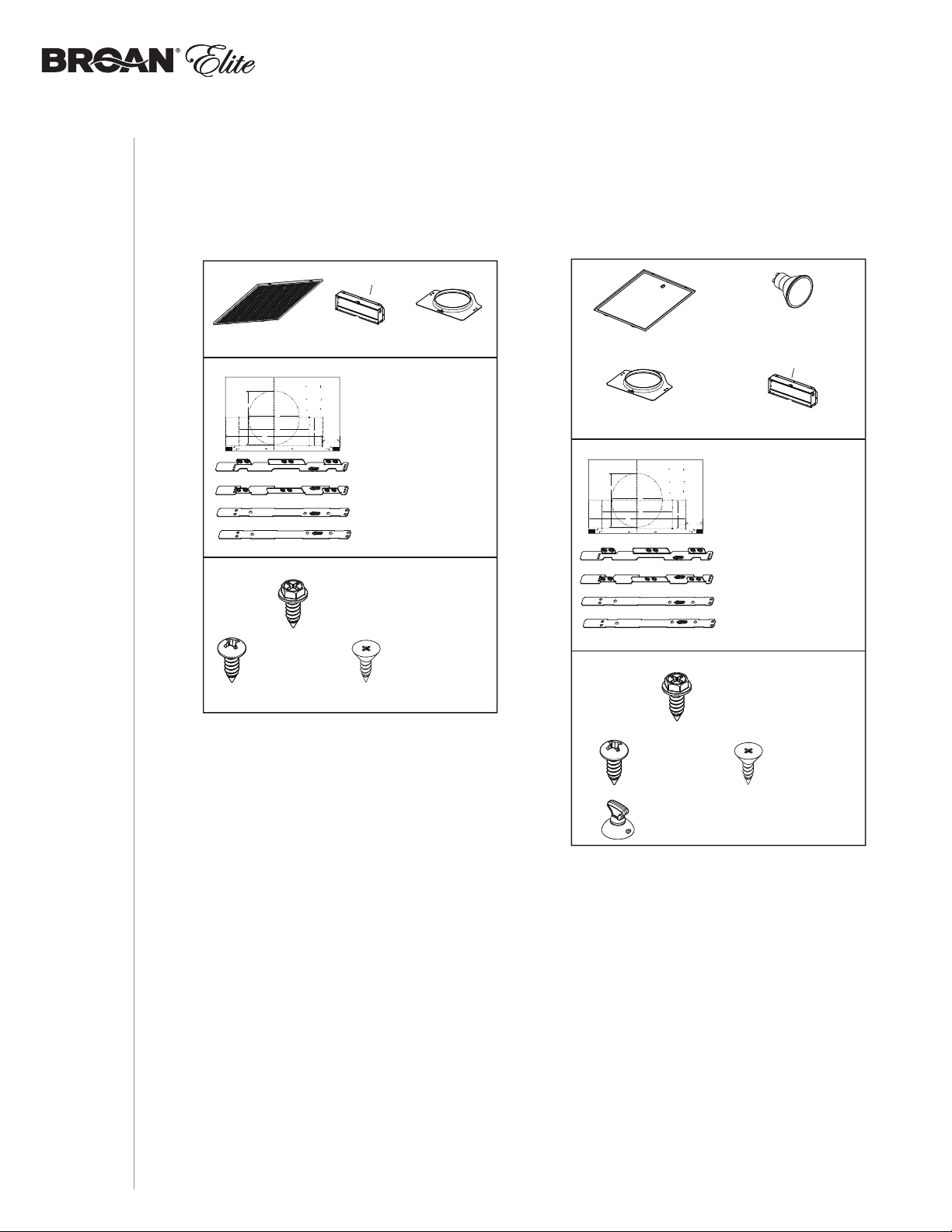
Contents
VERTICAL EXHAUST
VERTICAL EXHAUST
Before proceeding to the installation, check the contents of the box. If items are missing or
damaged, contact the manufacturer.
Make sure that the following items are included:
ALT2 Series ALT1 Series
* FIND INSIDE
HOOD
OF
(2) SHIELDED HALOGEN BULBS
(50W, GU10)
* FIND INSIDE OF HOOD
(1) 3¼” X 10”
D
AMPER ASSEMBLY*
(1) TEMPLATE FOR DUCTING
(PRINTED BOTH SIDES)
(2) INSTALLATION BRACKETS**
FOR FRAMED CABINET
Apoyar este borde contra la pared de atrásPlace this edge against back wall
EZ1 C
MARKWHEREINDICATED
FORTHEAPPROPRIATESIZE DUCTOPENING
OR
MARQUERLESREPÈRES AUX ENDROITS INDIQUÉS SELON
LEFORMATDECONDUIT UTILISÉ
OU
TITLETOBE TRANSLATED IN SPANISH
O
7 PULG.
DE
4¼”
D
RECTANGULAR DUCTING7” ROUND DUCTING
= 3¼” x 10”
= 3¼” x 14”
CONDUITRECTANGULAIRECONDUITRONDDE 7 PO
= 3¼ po x 10 po
= 3¼ po x 14 po
CONDUCTORECTANGULARCONDUCTOREDONDO
= 3¼ pulg. x 10 pulg.
= 3¼ pulg. x 14 pulg.
(1) 3¼”
AMPER ASSEMBLY*
OMPONENTS
Electrical access hole center
A = single blower hood
B = double blower hood
Centre du trou pour fil
d’alimentation électrique
A = hotte ventilateur simple
B = hotte ventilateur double
To be translated in Spanish
Electrical access hole center
A = single blower hood
B = double blower hood
AB
C
(2) GREASE FILTERS
Use this template for marking;do not attempt to cut out the ducting hole through it.
NOTE: These cutouts are clearance holes; they do not need to be the exact size of ducting.
Utiliser ce gabarit pour marquer vos repères;ne pas tenter de découper
le trou pour le conduit à travers le gabarit.
NOTE : Les découpes incluent le jeu nécessaire à l’installation; elles ne doivent pas
être du format exact des conduits.
Use esta plantilla para crear marcados;no trate de cortar el
agujero del conducto a través de la plantilla.
NOTA: To be translated in Spanish.
Bend template along graduated
scale when installing to framed
cabinet.
C
Pour une installation sous une
armoire à fond en retrait, utiliser les
lignes pour mesurer l’épaisseur du
décalage causé par le mur de
l’armoire et plier le gabarit en
8”
conséquence.
To be translated in Spanish.
C
L
7½”
10½”
14½”
C
Appuyer ce bord au mur arrière
** FIND EZ1 BRACKETS ATTACHED INSIDE OF HOOD
(1) PARTS BAG*** CONTAINING:
X 10”
(1) TEMPLATE FOR DUCTING
(PRINTED BOTH SIDES)
(2) INSTALLATION BRACKETS**
FOR FRAMED CABINET
(2) INSTALLATION BRACKETS**
FOR FRAMELESS CABINET
OUND
(1) 7” R
DUCT CONNECTOR
(2) GREASE FILTERS
(1) 7” R
DUCT CONNECTOR
Use this template for marking;do not attempt to cut out the ducting hole through it.
NOTE: These cutouts are clearance holes; they do not need to be the exact size of ducting.
Utiliser ce gabarit pour marquer vos repères;ne pas tenter de découper
le trou pour le conduit à travers le gabarit.
NOTE : Les découpes incluent le jeu nécessaire à l’installation; elles ne doivent pas
être du format exact des conduits.
Use esta plantilla para crear marcados;no trate de cortar el
agujero del conducto a través de la plantilla.
NOTA: To be translated in Spanish.
Bend template along graduated
scale when installing to framed
cabinet.
C
Pour une installation sous une
armoire à fond en retrait, utiliser les
lignes pour mesurer l’épaisseur du
décalage causé par le mur de
l’armoire et plier le gabarit en
8”
conséquence.
To be translated in Spanish.
C
L
7½”
10½”
14½”
C
Appuyer ce bord au mur arrière
OUND
Apoyar este borde contra la pared de atrásPlace this edge against back wall
MARKWHEREINDICATED
FORTHEAPPROPRIATESIZE DUCTOPENING
OR
MARQUERLESREPÈRES AUX ENDROITS INDIQUÉS SELON
LEFORMATDECONDUIT UTILISÉ
OU
TITLETOBE TRANSLATED IN SPANISH
O
DE
7 PULG.
4¼”
EZ1 C
RECTANGULAR DUCTING7” ROUND DUCTING
= 3¼” x 10”
= 3¼” x 14”
CONDUITRECTANGULAIRECONDUITRONDDE 7 PO
= 3¼ po x 10 po
= 3¼ po x 14 po
CONDUCTORECTANGULARCONDUCTOREDONDO
= 3¼ pulg. x 10 pulg.
= 3¼ pulg. x 14 pulg.
Electrical access hole center
A = single blower hood
B = double blower hood
Centre du trou pour fil
d’alimentation électrique
A = hotte ventilateur simple
B = hotte ventilateur double
To be translated in Spanish
Electrical access hole center
A = single blower hood
B = double blower hood
AB
C
OMPONENTS
(4) NO. 8-18 X 1/2”
M
ETAL SCREWS
O. 8 X 5/8”
(6) N
RD. HD.
W
OOD SCREWS
(6) NO. 8 X 1/2”
C
OUNTERSUNK
WOOD SCREWS
*** FIND PARTS BAG BEHIND THE DAMPER ASSEMBLY INSIDE OF HOOD
(2) INSTALLATION BRACKETS**
** FIND EZ1 BRACKETS
ATTACHED
(1) PARTS BAG*** CONTAINING:
(4) NO. 8-18 X 1/2”
M
ETAL SCREWS
(6) NO. 8 X 5/8”
RD. HD.
W
OOD SCREWS
(1) BULB SUCTION
CUP TOOL
FOR FRAMELESS CABINET
INSIDE OF HOOD
(6) NO. 8 X 1/2”
C
OUNTERSUNK
WOOD SCREWS
*** FIND PARTS BAG BEHIND
THE DAMPER ASSEMBLY
OF HOOD
INSIDE
INSTALLATION MANUAL
8
INSTALLATION
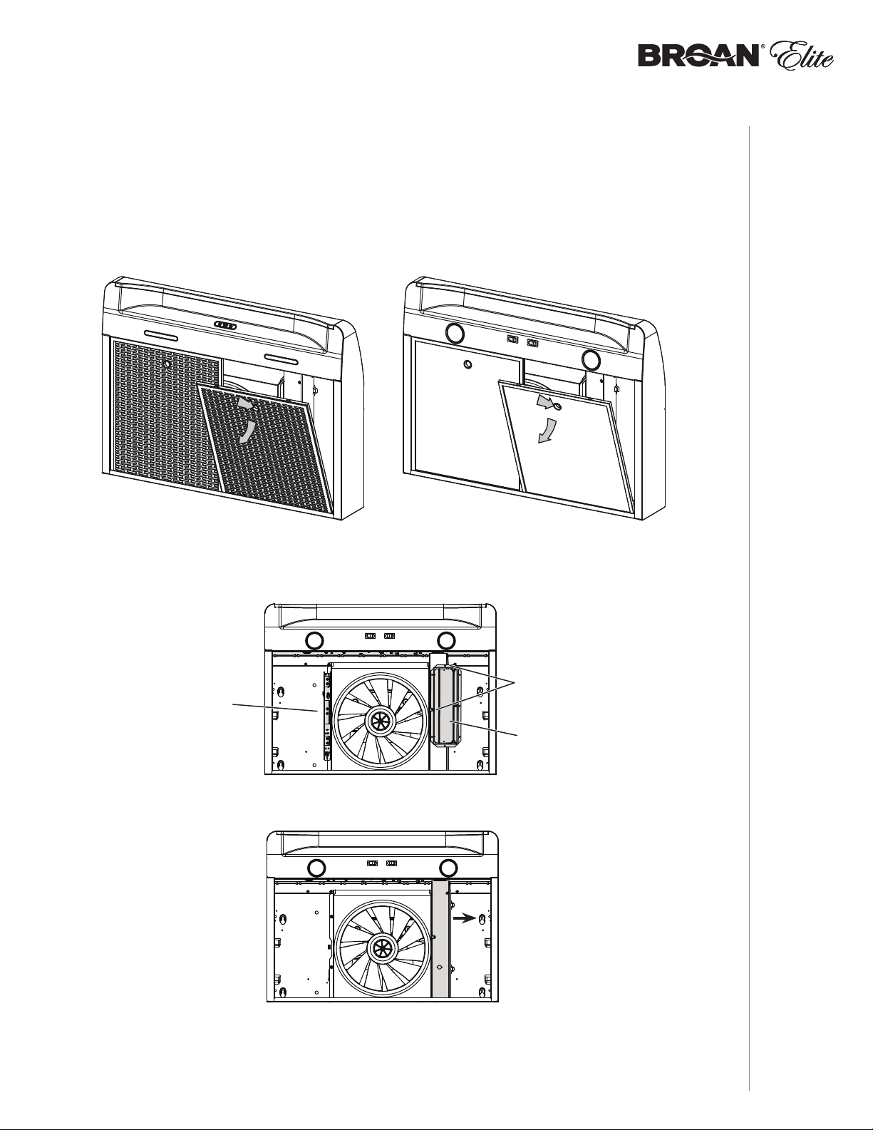
Prepare the Hood
NOTE: Since this manual covers many range hood models, some details in the following
illustrations may sligthly differ from your unit.
1 ] If present, remove all protective polyfilm from the hood and/or parts.
2 ] Using the finger cup, remove the grease filters from the hood by pushing down and tilting
filter out .
B
C
3 ] Remove the EZ1 brackets from inside the hood by cutting off the tie wrap. Remove both
screws holding damper assembly to hood. Remove parts bag (captured behind the damper
assembly). Remove damper assembly from inside the hood and keep the screws for further
use.
EZ1
BRACKETS
4 ] Remove the wiring cover (shaded part on illustration below) by sliding it out from the hood
and set it aside.
B
C
SCREWS
DAMPER
ASSEMBLY
INSTALLATION
9
INSTALLATION MANUAL

5 ] Remove 7” Round Duct Plate from top/back of hood (see illustration below). Keep the screws
for further use.
7” ROUND
DUCT
PLATE
2 SCREWS
6 ] Remove Electrical Power Cable Knockout from top (vertical wiring) or back (horizontal wiring)
of hood. Install an appropriate strain relief, 1/2” diameter (not included).
ELECTRICAL
POWER CABLE
KNOCKOUT
INSTALLATION MANUAL
INSTALLATION
NON-DUCTED INSTALLATION ONLY
7 ] Remove 3 screws retaining the recirculation cover plate (shaded part in illustration below)
to the hood. Discard this plate with its screws.
RECIRCULATION
COVER PLATE
SCREWS
10

DUCTED INSTALLATION ONLY
8 ] Remove 3¼” x 10” vertical, 3¼” x 10” horizontal, or 7-inch round knockout plate as
appropriate for your ducting method (see FIGURES 1 A and 1 B).
FIGURE 1 A
7” ROUND KNOCKOUT
PLATE (ALSO REMOVE
VERTICAL KNOCKOUT PLATE)
3¼” X 10”
VERTICAL
KNOCKOUT
PLATE
3¼” X 10”
HORIZONTAL
KNOCKOUT
PLATE
9 ] Attach 3¼” x 10” Damper Assembly on top OR back of hood (if using 3¼” x 10” duct; shaded
part in FIGURE 2 A below) or 7” Round Duct Plate (if using 7-inch round duct, FIGURE 3) over
the knockout opening. When installed, the 3¼” x 10” damper assembly must open as
shown in FIGURE 2 B.
FIGURE 2 A FIGURE 2 B
3¼” X 10”
DAMPER
ASSEMBLY
SCREWS
FIGURE 1 B
TOP/BACK
EDGE OF
HOOD
DAMPER
FLAP
PIVOT
SCREWS
3¼” X 10”
DAMPER
ASSEMBLY
FIGURE 3
7” ROUND
SCREWS
BACK OF
HOOD
DAMPER
FLAP
PIVOT
DUCT
PLATE
NOTE: To accommodate off-center ductwork, the 7” round duct plate can be installed up
to 1/2” on either side of the hood center.
TIP: Insert a small length of duct over the 3¼” x 10” damper assembly (for rectangular ducting)
or 7” round (for round ducting) and seal the joint using aluminum foil duct tape to ease
connection with the house ductwork.
INSTALLATION
INSTALLATION MANUAL
11
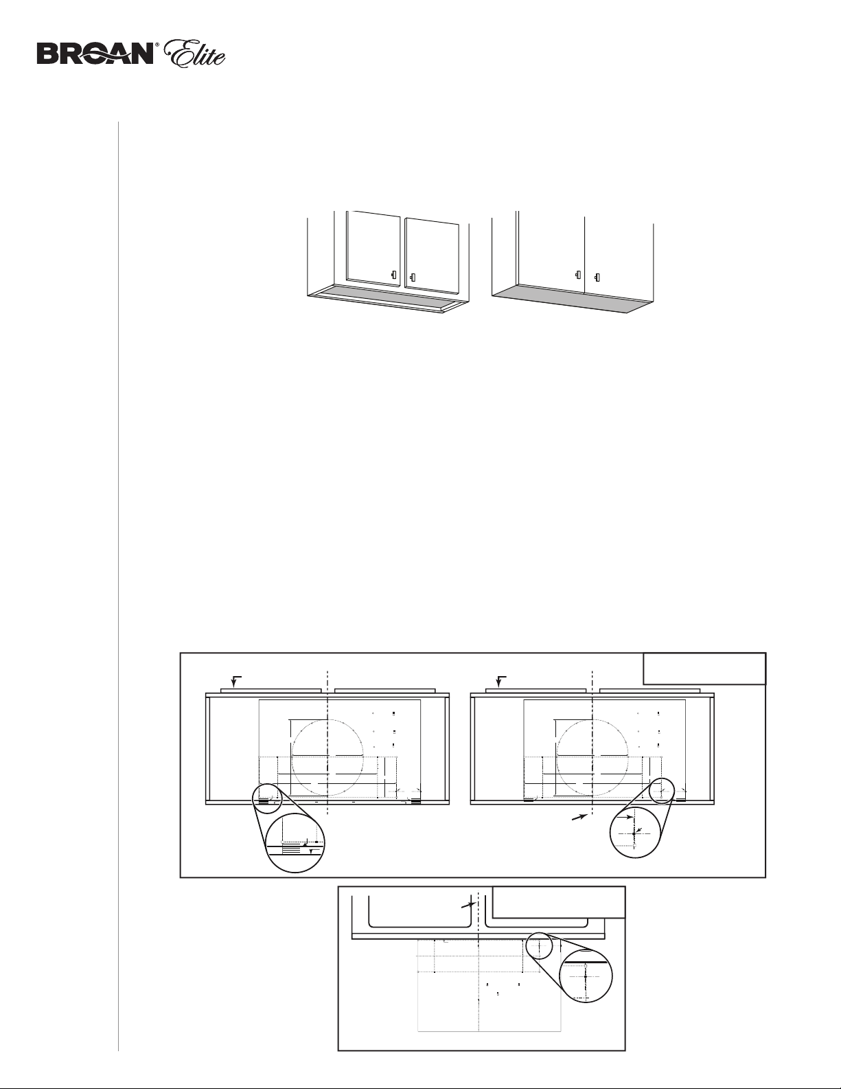
Prepare the Hood Location
VERTICAL EXHAUST
VERTICAL EXHAUST
NOTE: Before starting installation, read all the steps of these instructions.
Use the illustration below to identify your kitchen cabinet type.
FRAMED CABINET FRAMELESS CABINET
This manual covers 2 kinds of installation: the standard (without EZ1 brackets) and the
EZ1 one-person installation system (using included template and brackets).
For the standard installation, go to page 17.
EZ1 one-person installation system
EZ1 installation is designed for use with kitchen cabinets that have the same width designation
as the range hood width. If the cabinet is greater than 1/2” wider than the range hood width,
please use the standard installation method.
1 ] Use the proper template for vertical OR horizontal discharge (included) for placement of
ductwork and electrical cutout in cabinet or wall. For a non-ducted installation, DO NOT cut a
duct access hole, only cut the hole for electrical wiring. If replacing a hood and plan to use
the existing duct and electrical, steps 2 to 5 may not be necessary. If so, skip to step 6.
2 ] Measure and mark the hood center line on cabinet bottom.
3 ] Align the center line on template with the hood center line marked on the bottom of the
cabinet, placing the edge (where indicated) of the template against back wall. When using
with framed cabinet for vertical exhaust installation, fold over rear edge of template equal
to the depth of the cabinet frame at the wall (use graduations on template, C locations on
template). Tape the template in place.
NOTE: When facing the installation, A and B (on template) must be at right.
VERTICAL EXHAUST
CABINET FRONT
CABINET FRONT
DUCTING
INSTALLATION MANUAL
INSTALLATION
12
Use this template for marking;do not attempt to cut out the ducting hole through it.
NOTE: These cutouts are clearance holes; they do not need to be the exact size of ducting.
Utiliser ce gabarit pour marquer vos repères;ne pas tenter de découper
le trou pour le conduit à travers le gabarit.
NOTE : Les découpes incluent le jeu nécessaire à l’installation; elles ne doivent pas
être du format exact des conduits.
Use esta plantilla para crear marcados;no trate de cortar el
agujero del conducto a través de la plantilla.
NOTA: To be translated in Spanish.
Bend template along graduated
scale when installing to framed
cabinet.
C
Pour une installation sous une
armoire à fond en retrait, utiliser les
lignes pour mesurer l’épaisseur du
décalage causé par le mur de
l’armoire et plier le gabarit en
8”
conséquence.
To be translated in Spanish.
C
C
MARKWHERE INDICATED
FORTHE APPROPRIATE SIZE DUCT OPENING
RECTANGULAR DUCTING7” ROUND DUCTING
OR
= 3¼” x 10”
= 3¼” x 14”
MARQUERLES REPÈRES AUX ENDROITS INDIQUÉSSELON
LEFORMATDE CONDUITUTILISÉ
CONDUITRECTANGULAIRECONDUITROND DE 7 PO
OU
= 3¼ po x 10 po
= 3¼ po x 14 po
TITLETO BE TRANSLATED IN SPANISH
CONDUCTORECTANGULARCONDUCTOREDONDO
O
= 3¼ pulg. x 10 pulg.
7 PULG.
C
14½”
Appuyer ce bord au mur arrière
L
DE
= 3¼ pulg. x 14 pulg.
4¼”
Electrical access hole center
A = single blower hood
B = double blower hood
Centre du trou pour fil
d’alimentation électrique
A = hotte ventilateur simple
B = hotte ventilateur double
To be translated in Spanish
Electrical access hole center
A = single blower hood
B = double blower hood
AB
C
7½”
10½”
Apoyar este borde contra la pared de atrásPlace this edge against back wall
FOLD TEMPLATE ALONG GRADUATED
SCALE
WHEN INSTALLING TO FRAMED
P
CABINET
.
CENTER LINE
Place this edge against
cabinet bottom.
Appuyer ce bord contre le bas
de l’armoire.
Apoyar este borde contra
la base del armario.
Use this template for marking;do not attempt to cut out the ducting hole through it.
NOTE: These cutouts are clearance holes; they do not need to be the exact size of ducting.
Utiliser ce gabarit pour marquer vos repères;ne pas tenter de découper
le trou pour le conduit à travers le gabarit.
NOTE : Les découpes incluent le jeu nécessaire à l’installation; elles ne doivent pas
être du format exact des conduits.
Use esta plantilla para crear marcados;no trate de cortar el
agujero del conducto a través de la plantilla.
NOTA: To be translated in Spanish.
Bend template along graduated
scale when installing to framed
cabinet.
C
Pour une installation sous une
armoire à fond en retrait, utiliser les
lignes pour mesurer l’épaisseur du
décalage causé par le mur de
l’armoire et plier le gabarit en
8”
conséquence.
To be translated in Spanish.
C
CENTER LINE
HORIZONTAL EXHAUST
DUCTING
AB
Electrical access hole center
A = single blower hood
B = double blower hood
Centre du trou pour fil
d’alimentation électrique
ple
A = hotte ventilateur sim
B = hotte ventilateur double
MARQUERLESREPÈRES AUXENDROITS INDIQUÉS SELON
LEFORMATDE CONDUIT UTILISÉ
CONDUITRECTANGULAIRE
= 3¼ po x 10 po
= 3¼ po x 14 po
To be translated in Spanish
Electrical access hole center
A = single blower hood
B = double blower hood
ELECTRICAL
ACCESS HOLE
LOCATION (A)
(
C
L
MARKWHEREINDICATED
FORTHEAPPROPRIATE SIZE DUCTOPENING
RECTANGULAR DUCTING
= 3¼” x 10”
= 3¼” x 14”
TITLETOBE TRANSLATEDIN SPANISH
CONDUCTORECTANGULAR
= 3¼ pulg. x 10 pulg.
= 3¼ pulg. x 14 pulg.
C
L
14½”
A
Electrical access hol
A = single blower ho
B = double blower
Centre du tr
d’alim
IN WALL)
MARKWHERE INDICATED
FORTHE APPROPRIATE SIZE DUCT OPENING
RECTANGULAR DUCTING7” ROUND DUCTING
OR
= 3¼” x 10”
= 3¼” x 14”
MARQUERLES REPÈRES AUX ENDROITS INDIQUÉSSELON
LEFORMATDE CONDUITUTILISÉ
CONDUITRECTANGULAIRECONDUITROND DE 7 PO
OU
= 3¼ po x 10 po
= 3¼ po x 14 po
TITLETO BE TRANSLATED IN SPANISH
CONDUCTORECTANGULARCONDUCTOREDONDO
O
= 3¼ pulg. x 10 pulg.
7 PULG.
DE
= 3¼ pulg. x 14 pulg.
7½”
10½”
Electrical access hole center
A = single blower hood
B = double blower hood
Centre du trou pour fil
d’alimentation électrique
A = hotte ventilateur simple
B = hotte ventilateur double
To be translated in Spanish
Electrical access hole center
4¼”
A = single blower hood
B = double blower hood
AB
A
C
C
ELECTRICAL
ACCESS HOLE
LOCATION (A)
IN CABINET BOTTOM)
(

4 ] Drill a 1/8” dia. pilot hole for house wiring, at A location on template.
5 ] Use a sharp pencil or 1/8” drill bit to mark the locations for the appropriate duct access
holes (16 locations for 7” round duct, or 4 corner locations for rectangular duct). Remove the
template.
6 ] Draw the border for the exhaust ducting by linking its marks (16 for round duct and 4 for
rectangular duct), then cut the opening in the cabinet bottom (vertical exhaust) or in the wall
(horizontal exhaust). Drill the house wiring hole by using a 1½” hole saw centered with the
pilot hole previously made in 4.
7 ] Install the proper installation brackets according to the type of cabinet (framed or frameless).
See below.
FRAMED CABINET
Refer to the marking on brackets to determine the correct installation side and orientation.
XY
7/64”
Z
Mate the corresponding bracket to the cabinet side frame, while placing rear end
of bracket against the wall. Use a pencil to mark 3 holes (there are 6 holes but only
3 are necessary).
INSTALLATION
INSTALLATION MANUAL
Remove the bracket. Using a 7/64” drill bit, drill 3 holes where marked.
Assemble the bracket to the side frame using a Phillips screwdriver and 3 provided
no. 8 x 5/8” wood screws. Repeat for the other side frame.
13

FRAMELESS CABINET
Refer to the marking on brackets to determine the correct installation side and orientation.
X
Y
3 X
Z
[ \
7/64”
Align the corresponding bracket to the cabinet side, while placing rear end of bracket
against the wall. Draw a line on the outer edge of the bracket (as shown).
Slide the bracket towards the center of cabinet and align side edge to marked line,
keeping the rear end edge leaning on the wall.
Use a pencil to mark 3 holes.
INSTALLATION MANUAL
14
Remove the bracket. Using a 7/64” drill bit, drill 3 holes where marked.
Assemble the bracket to the cabinet bottom using a Phillips screwdriver and 3 provided
countersunk wood screws. Repeat for the other cabinet side.
INSTALLATION
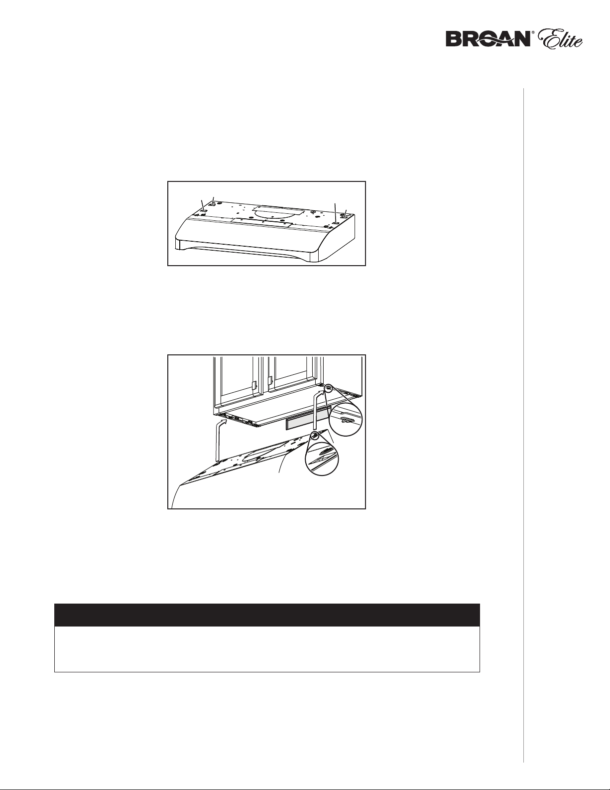
Install the Hood (EZ1 Bracket)
OTE: N The following procedure applies to both frame or frameless cabinet installations.
1 ] Run house power cable between service panel and hood location.
2 ] There are 2 pairs of recessed holes on each side of the top of the hood (on rear: A and B,
on front C and D on illustration below); these holes allow the range hood to hang on the
brackets (previously installed).
A
C
HORIZONTAL EXHAUST INSTALLATION ONLY
3 ] Temporarily hang the hood on the brackets using its (2) recessed REAR HOLES (A and B).
While holding the hood, run the house power cable into the hood through the strain relief
previously installed in step 6 on page 10.
D
B
A
B
4 ] Unhook the rear holes from the brackets and hang the hood using its (2) recessed FRONT
HOLES (C and D). Attach power cable to the hood using the strain relief.
VERTICAL EXHAUST INSTALLATION AND NON-DUCTED INSTALLATION ONLY
5 ] Hang the hood on the brackets using the (2) recessed FRONT HOLES (C and D). While
holding the hood, run the house power cable into the hood through the strain relief previously
installed in step 6 on page 10. Secure power cable to the hood using the strain relief.
DUCTED INSTALLATION ONLY
6 ] Connect ductwork to hood and use metal foil duct tape to make joints secure and air-tight.
Make sure the damper assembly (or round duct plate) enters the ductwork and that the
damper opens and closes freely.
NOTE: See final installation steps on next page.
INSTALLATION
INSTALLATION MANUAL
15

7 ] For framed cabinet, secure the hood to the EZ1 brackets using 4 no. 8-18 x 1/2” metal screws
(included in parts bag). Insert 2 screws per side, in the slots (as shown in insets on illustration
below).
8 ] For frameless cabinet, secure the hood to the cabinet using 4 no. 8 x 5/8” round head wood
screws (included in parts bag). Insert 2 screws per side, in the slots (as shown in insets on
illustration below).
FRAMED CABINET FRAMELESS CABINET
METAL
SCREWS
WOOD
SCREWS
INSTALLATION MANUAL
16
INSTALLATION
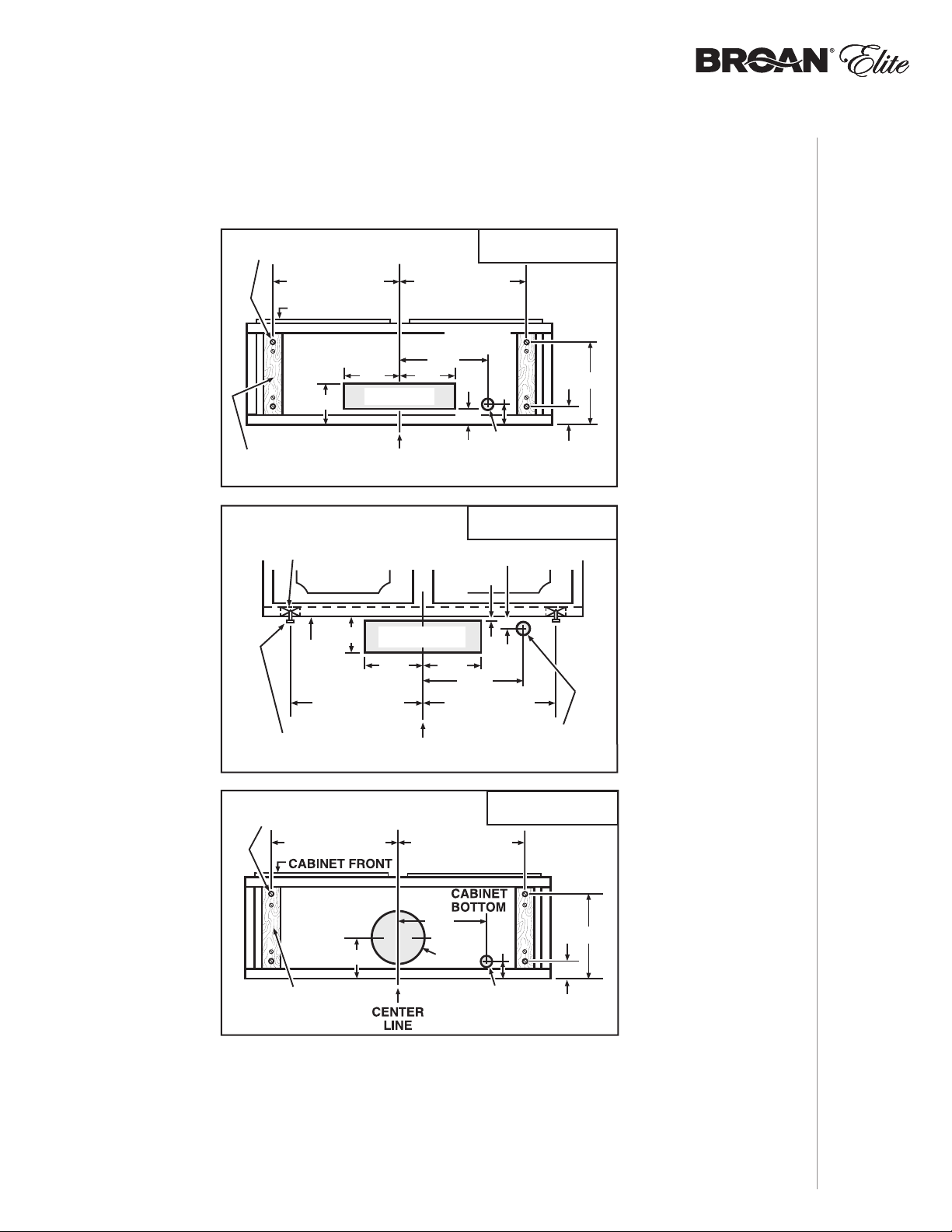
Standard Installation (without EZ1 brackets)
VERTICAL DUCT
ACCESS HOLE
1015/16"
5¼"
5¼"
CENTER
LINE
HOOD MOUNTING SCREWS (4)
ELECTRICAL
ACCESS HOLE
(
IN CABINET BOTTOM)
WOOD SHIMS
(
RECESSED-BOTTOM
CABINETS
ONLY)
CABINET FRONT
3/4"
1⅜"
1½"
7³/16"
12⅞" (30" HOOD)
15⅞" (36"
HOOD)
47/16"
CABINET
BOTTOM
12⅞" (30"
HOOD)
15⅞" (36"
HOOD)
CABINET
BOTTOM
CABINET FRONT
HORIZONTAL DUCT
ACCESS HOLE
HOOD
MOUNTING
SCREWS (4)
ELECTRICAL
ACCESS HOLE
(
IN WALL)
3⅞"
CENTER
LINE
WOOD SHIMS
(
RECESSED-BOTTOM
CABINETS
ONLY)
13/16"
3/16"
5¼"
5¼"
12⅞" (30" HOOD)
15⅞" (36"
HOOD)
12⅞" (30"
HOOD)
15⅞" (36"
HOOD)
7³/
16"
7-IN. ROUND
DUCT
ACCESS
HOLE
1 ] Use the proper diagram below for placement of ductwork and electrical cutout in cabinet
or wall. For a non-ducted installation, DO NOT cut a duct access hole, only cut the hole for
electrical wiring.
3¼" X 10"
VERTICAL DUCTING
3¼" X 10"
HORIZONTAL DUCTING
2 ] Install part-way four (4) ROUND HEAD no. 8 x 5/8” mounting screws into shims/cabinet,
according to the proper diagram above. (Mounting screws are included in parts bag, but wood
shims and shim mounting screws are not included).
HOOD MOUNTING SCREWS (4)
12⅞" (30"
15⅞" (36"
HOOD)
HOOD)
7-IN. ROUND
7-IN. ROUND
4¹¹/16"
WOOD SHIMS
RECESSED-BOTTOM
(
CABINETS
ONLY)
DUCT
DUCT
ACCESS
ACCESS
HOLE
HOLE
12⅞" (30"
15⅞" (36"
7³/
16"
8" DIA.
HOLE
ACCESS HOLE
IN CABINET BOTTOM)
(
7-IN. ROUND
VERTICAL DUCTING
HOOD)
HOOD)
1⅜"
ELECTRICAL
1½"
10
INSTALLATION
15
/16"
INSTALLATION MANUAL
17

Install the Hood (Standard Installation)
OTE: N Two installers are recommended because of the weight of this hood.
1 ] Run house power cable between service panel and hood location. Run the house power cable
into the hood through the strain relief previously installed in step 6 on page 10.
2 ] Hang hood from (4) mounting screws previously installed. Slide hood back towards wall until
mounting screw heads are engaged in narrow end of keyhole slots in top of hood. While
holding the hood, tighten screws securely. Attach power cable to the hood using the strain
relief.
DUCTED INSTALLATION ONLY
3 ] Connect ductwork to hood and use metal foil duct tape to make joints secure and air-tight.
Make sure the damper assembly (or round duct plate) enters the ductwork and that the
damper opens and closes freely.
INSTALLATION MANUAL
18
INSTALLATION
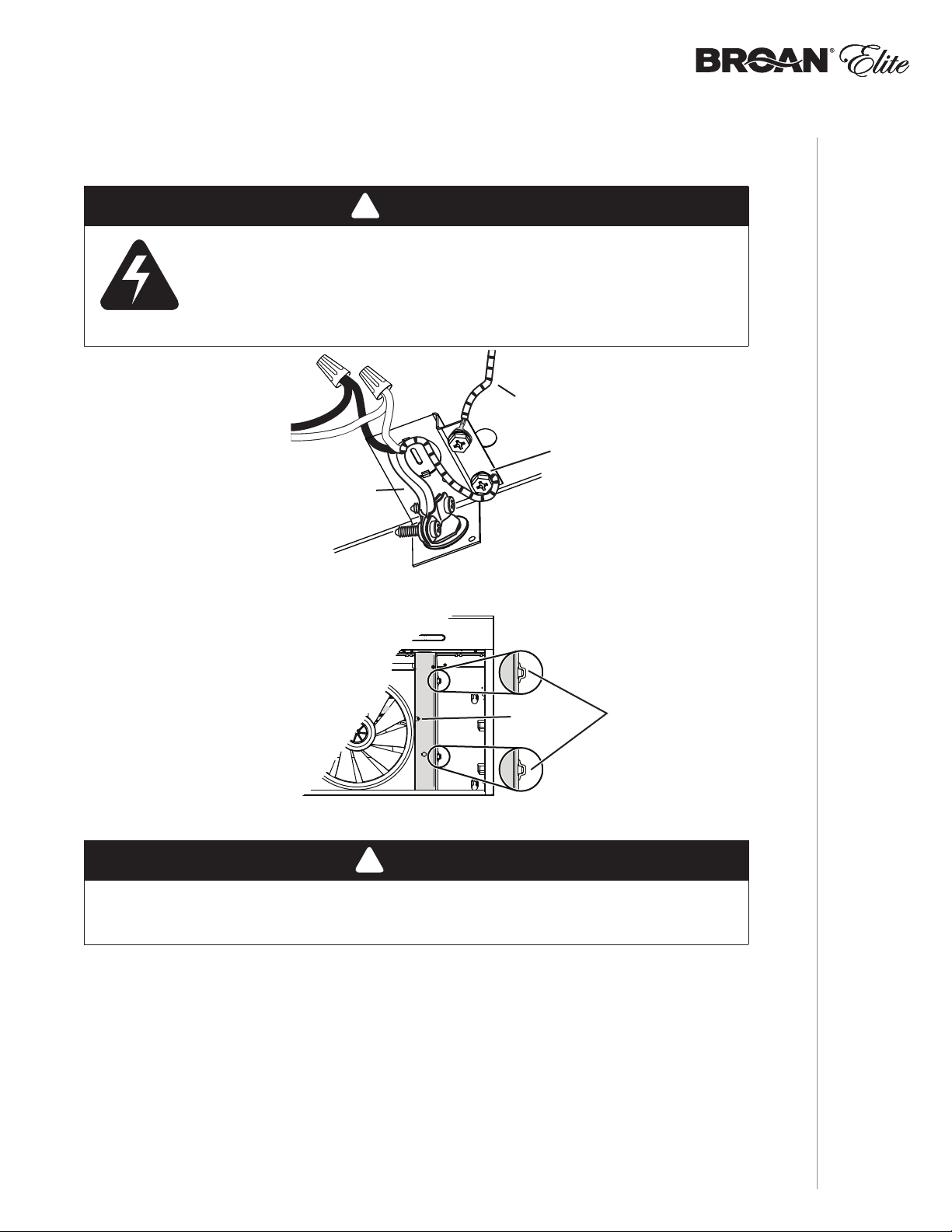
Connect the Wiring
!
WARNING
Risk of electric shock. Electrical wiring must be done by qualifi ed
personnel in accordance with all applicable codes and standards.
Before connecting wires, switch power off at service panel and lock
service disconnecting means to prevent power from being switched
on accidentally.
MOTOR
GROUND
WIRE
GROUND
SCREW
HOUSE
POWER CABLE
1 ] Connect House Power Cable to range hood wiring: BLACK to BLACK, WHITE to WHITE and
GREEN or bare wire under GREEN ground screw.
TABS ON INNER
TOP OF HOOD
SCREW
2 ] Reinstall wiring cover and attach it to the hood using its retaining screw.
!
CAUTION
Ensure both tabs on inner top of hood are engaged in their corresponding slots in
wiring cover. Also, take care not to pinch wires while reinstalling wiring cover.
ENGAGED IN
WIRING COVER
SLOTS.
INSTALLATION
INSTALLATION MANUAL
19

Light Bulbs (ALT1 Series only)
The ALT1 Series range hoods require two shielded Halogen Bulbs (120 V, 50 W max., MR16 or
PAR16 with GU10 base), included.
NOTE: Before using lamps, remove shipping tape on them (if present).
!
WARNING
Do not touch lamps during or soon after operation. Burns may occur. In order to prevent
the risk of personal injury, only install shielded halogen lamps. Also, never install a cool
beam, a dichroic lamp, a lamp not suitable for use in recessed luminaires or identified for
use in enclosed fixtures.
BULB LEADS
1 ] Align the bulb leads with the small indentations located on the border of the lamp location on
hood (see inset above), then install the bulbs by placing the bulb leads into their grooves in
the socket.
2 ] Gently push upwards and turn clockwise until secure.
NOTE: The Suction Cup Tool (included with hood) can be used to install and remove light bulbs.
Press suction cup tool on bulb and rotate counterclockwise to remove bulb or clockwise to
install bulb.
Most GU10 LED replacement bulbs commonly found in the market are not designed
for use in a cooking environment and might not perform as advertised. Their usage
with this product is not recommended.
BULB LEAD
GROOVES
(IN SOCKET)
!
CAUTION
SUCTION
CUP TOOL
INSTALLATION MANUAL
20
Install the Filters
Ducted Installation Only:
Re-install grease filters removed in step 2 , page 9, under “Prepare the Hood”.
Non-ducted Installation Only:
Purchase two non-ducted filters from your local distributor or retailer (see product specification
label for filter type). Attach the non-ducted filters following instructions packed with the
non-ducted filter.
INSTALLATION

ALT1 SERIES
12 34 56
1
2
3
4
J6
Override
J4
LED
J10
Interface
1
2
3
4
5
6
7
8
User interface mounted
to J10 on back of
control board.
J1
Transformer
J2
Power, Motor
5
4
3
2
1
5
4
3
2
1
6
7
Control Board
R
R
BL
BL
BK
W
BK
BK
W
G/Y
R (Low)
O (Medium)
BK (High)
W
120 V AC
Line
Neutral
Ground
G/Y
W
BK
O
R
FAN MOTOR
BN
BN/W
R
BK
LED
LED
W
COLOR CODE
BK
BL
BN
BN/W
BLACK
BLUE
BROWN
BROWN/WHITE
G/Y
O
R
W
GREEN/YELLOW
ORANGE
RED
WHITE
1
2
3
4
5
6
Light Switch
COLOR CODE
BROWN/WHITE
BLACK
BK
BLUE
BL
BROWN
BN
1
2
BN/W
G/Y
O
BL (High)
Y (Low)
GREEN/YELLOW
ORANGE
RED
R
WHITE
W
YELLOW
Y
BK
BK
Line
Neutral
Ground
120 V AC
ALT2 SERIES
BK
Motor Switch
W
W
1
2
R (Low)
BK (High)
G/Y
W
W
BK
6
5
4
3
2
1
FAN MOTOR
R
O
BK
G/Y
W
BN
BN/W
WIRING DIAGRAMS
INSTALLATION MANUAL
21

ALT2 SERIES
C
B
K
INSTALLATION MANUAL
22
SERVICE PARTS
D
E
I
J
F
G
KEY
NO.
10
* ITEM NOT SHOWN.
REPLACEMENT PARTS AND REPAIRS
In order to ensure your unit remains in good working condition, you must use Broan-NuTone LLC or Venmar Ventilation ULC genuine
replacement parts only. Broan-NuTone LLC or Venmar Ventilation ULC genuine replacement parts are specially designed for each
unit and are manufactured to comply with all the applicable certification standards and maintain a high standard of safety. Any third
party replacement part used may cause serious damage and drastically reduce the performance level of your unit, which will result in
premature failing. Broan-NuTone LLC and Venmar Ventilation ULC recommend to contact a certified service depot for all replacement
parts and repairs.
ART NO.DESCRIPTION
P
S97020029 R
S97020030
1
S97020031
S98011873
2 SR680508 7'' R
3 S97020534 3¼” X 10” DAMPER ASS’Y (INCL. SCREWS)11111111
4 S97020409
5 S97020407 F
6 SR99420635 C
S99010431-002
7
S99010431-003
8 S97020444 LED
9 S97020445 T
S97020431
S97020432
S97020433
* S97020452 W
* S98011637 W
* S97020360
S97020466
*
S97020467
* S99527587 NON-DUCTED FILTER CLIP KIT (INCL. 4 CLIPS)11111111
* S97020470 E
ECIRC. COVER PLATE, BLACK (INCL. SCREWS)1 1
ECIRCULATION COVER PLATE, WHITE
R
(INCLUDING SCREWS)
ECIRC. COVER PLATE, STAINLESS STEEL
R
(INCLUDING SCREWS)
ECIRCULATION COVER PLATE, BLACK
R
STAINLESS (INCLUDING SCREWS)
OUND DUCT PLATE (INCL. SCREWS)11111111
LOWER MOTOR (INCLUDING CAPACITOR
B
AND 4 SCREWS)
ANPELLER (INCLUDING ITEM 6) 11 1111 11
LIP FOR FANPELLER 11 1111 11
REASE FILTER - MICRO MESH OBLONG
G
-TYPE C3 (SET OF 2)
GREASE FILTER - MICRO MESH OBLONG
-TYPE D3 (SET OF 2)
MODULE (PAIR) 11 1111 11
RANSFORMER 24 V 18 VA (WITH SCREWS)11111111
C
APTOUCH CONTROL LED,
STAINLESS (WITH SCREWS)
APTOUCH CONTROL LED, WHITE
C
(WITH SCREWS)
APTOUCH CONTROL LED, BLACK
C
(
WITH SCREWS)
IRE HARNESS 11 1111 11
IRING COVER 11 1111 11
ARTS BAG INCLUDING: 4 METAL SCREWS
P
. 8-18 X 1/2”, 6 ROUND HEAD
NO
NO. 8 X 5/8” WOOD SCREWS, 6 NO. 8 X 1/2”
COUNTERSUNK WOOD SCREWS
ON-DUCTED F ILTER - TYPE X C ( SET OF 2)
N
NON-DUCTED INSTALLATION ONLY)
(
ON-DUCTED F ILTER - TYPE X D ( SET OF 2)
N
NON-DUCTED INSTALLATION ONLY)
(
ASY INSTALL KIT (INCL. HARDWARE)11 11 1 11
B
H
30"
30"
B
LACK
LACK
STAINLESS
11
11 1111 11
11 11
11 11
11 1111 11
11 11
30"
TAINLESS
S
QUANTITY
30"
36"
HITE
W
B
11
11
11
11
36"
B
LACK
LACK
TAINLESS
S
11 11
11 11
36"
TAINLESS
S
W
36"
HITE

ALT1 SERIES
D
C
B
J
E
I
F
G
KEY
NO.
1
2 SR680508 7'' R
3 S97020534 3¼”
4 S97020408 B
5 S97020407 F
6 SR99420635 C
7
8
9 SV05921 S
* S97020448 W
* S98011637 W
* S97020292
*
* S99527587 N
* S97020470 E
TEM NOT SHOWN.
* I
ART NO.DESCRIPTION
P
S97020029 R
S97020030 R
S97020031 R
S99010434-002 G
S99010434-003 G
S99030367 R
S99030355 R
S99030356 R
S97020466
S97020467
H
30"
ECIRCULATION COVER PLATE, BLACK (INCLUDING SCREWS)1 1
ECIRCULATION COVER PLATE, WHITE (INCLUDING SCREWS)1 1
ECIRC. COVER PLATE, STAINLESS STEEL (INCL. SCREWS)1 1
OUND DUCT PLATE (INCLUDING SCREWS) 111111
X 10” DAMPER ASSEMBLY (INCLUDING SCREWS) 111111
LOWER MOTOR (INCLUDING CAPACITO R AND 4 SCREWS)111111
ANPELLER (INCLUDING ITEM 6) 111111
LIP FOR FANPELLER 111111
REASE FILTER - MICRO MESH -TYPE C2 (SET OF 2) 1 1 1
REASE FILTER - MICRO MESH -TYPE D2 (SET OF 2) 1 1 1
OCKER SWITCH, GREY (SET OF 2) 1 1
OCKER SWITCH, WHITE (SET OF 2) 1 1
OCKER SWITCH, BLACK (SET OF 2) 1 1
HIELDED HALOGEN BULBS 50 W GU10 2 2 2 2 2 2
IRE HARNESS 111111
IRING COVER 111111
P
ARTS BAG INCLUDING: 4 METAL SCREWS NO. 8-18 X 1/2”,
OUND HEAD NO. 8 X 5/8” WOOD SCREWS, 6 NO. 8 X 1/2”
6 R
C
OUNTERSUNK WOOD SCREWS, 1 SUCTION CUP TOOL
ON-DUCTED FILTER - TYPE XC (SET OF 2)
N
(
NON-DUCTED INSTALLATION ONLY)
ON-DUCTED FILTER - TYPE XD (SET OF 2)
N
NON-DUCTED INSTALLATION ONLY)
(
ON-DUCTED FILTER CLIP KIT (INCL. 4 CLIPS) 111111
ASY INSTALL KIT (INCLUDING HARDWARE) 111111
B
30"
S
LACK
TAINLESS
111111
111
QUANTITY
30"
W
HITE
B
36"
36"
S
LACK
TAINLESS
111
36"
W
HITE
SERVICE PARTS
INSTALLATION MANUAL
REPLACEMENT PARTS AND REPAIRS
In order to ensure your unit remains in good working condition, you must use Broan-NuTone LLC genuine replacement parts only. BroanNuTone LLC genuine replacement parts are specially designed for each unit and are manufactured to comply with all the applicable
certification standards and maintain a high standard of safety. Any third party replacement part used may cause serious damage and
drastically reduce the performance level of your unit, which will result in premature failing. Broan-NuTone LLC recommends to contact a
certified service depot for all replacement parts and repairs.
23

INSTALLATION MANUAL
24
Warranty Period and Exclusions: Broan-NuTone LLC and Venmar Ventilation ULC (either being the “Company”) warrants to the
original consumer purchaser of its product (“you”) that the product (the “Product”) will be free from material defects in the Product or
its workmanship for a period of one (1) year from the date of original purchase (or such longer period as may be required
by applicable law). For Range Hood Product that includes built-in LED modules, the Company warrants the LED modules and
driver to be free from material defects for a period of three (3) years from the date of purchase. The limited warranty period for
any replacement parts provided by the Company and for any Products repaired or replaced under this limited warranty shall
be the remainder of the original warranty period (or such longer period as may be required by applicable law).
This warranty does not cover fluorescent lamp starters, tubes, halogen and incandescent bulbs, fuses, filters, ducts, roof
caps, wall caps and other accessories for ducting that may be purchased separately and installed with the Product. This
warranty also does not cover (a) normal maintenance and service, (b) normal wear and tear, (c) any Products or parts
which have been subject to misuse, abuse, abnormal usage, negligence, accident, improper or insufficient maintenance,
storage or repair (other than repair by the Company), (d) damage caused by faulty installation, or installation or use
contrary to recommendations or instructions, (e) any Product that has been moved from its original point of installation,
(f) damage caused by environmental or natural elements, (g) damage in transit, (h) natural wear of finish, (i) Products
in commercial or nonresidential use, or (j) damage caused by fire, flood or other act of God or (k) Products with altered,
defaced or removed serial numbers. This warranty covers only Products sold to original consumers in the United States and
Canada by the Company or its U.S. and Canadian distributors authorized by the Company.
This warranty supersedes all prior warranties and, subject to applicable law, is not transferable from the original consumer purchaser.
No Other Warranties: This Limited Warranty contains the Company’s sole obligation and your sole remedy for defective
products. The foregoing warranties are exclusive and in lieu of any other warranties and conditions, express or implied. THE
COMPANY DISCLAIMS AND EXCLUDES ALL OTHER EXPRESS WARRANTIES AND CONDITIONS, AND DISCLAIMS
AND EXCLUDES ALL WARRANTIES AND CONDITIONS IMPLIED BY LAW, INCLUDING WITHOUT LIMITATION
THOSE OF MERCHANTABILITY AND FITNESS FOR A PARTICULAR PURPOSE. To the extent that applicable law
prohibits the exclusion of implied warranties or conditions, the duration of any applicable implied warranty or condition is
limited to the period specified for the express warranty above. Some jurisdictions do not allow limitations on how long an
implied warranty lasts, so the above limitation may not apply to you. Any oral or written description of the Product is for the
sole purpose of identifying it and shall not be construed as an express warranty.
Whenever possible, each provision of this Limited Warranty shall be interpreted in such manner as to be effective and valid
under applicable law, but if any provision is held to be prohibited or invalid, such provision shall be ineffective only to the
extent of such prohibition or invalidity, without invalidating the remainder of such provision or the other remaining provisions
of the Limited Warranty.
Remedy: During the applicable limited warranty period, the Company will, at its option, provide replacement parts for, or
repair or replace, without charge, any Product or part thereof, to the extent the Company finds it to be covered by and in
breach of this limited warranty under normal use and service. The Company will ship the repaired or replaced Product or
replacement parts to you at no charge. You are responsible for all costs for removal, reinstallation and shipping, insurance or
other freight charges incurred in the shipment of the Product or part to the Company. If you must send the Product or part to
the Company, as instructed by the Company, you must properly pack the Product or part—the Company is not responsible
for damage in transit. The Company reserves the right to utilize reconditioned, refurbished, repaired or remanufactured
Products or parts in the warranty repair or replacement process. Such Products and parts will be comparable in function
and performance to an original Product or part and warranted for the remainder of the original warranty period (or such
longer period as may be required by applicable law).
Company reserves the right, in its sole discretion, to refund the money actually paid by you for the Product in lieu of repair or
replacement. If the Product or component is no longer available, replacement may be made with a similar product of equal
or greater value, at Company’s sole discretion. This is your sole and exclusive remedy for breach of this limited warranty.
Exclusion of Damages: THE COMPANY’S OBLIGATION TO PROVIDE REPLACEMENT PARTS, OR REPAIR,
REPLACE OR REFUND, AT THE COMPANY’S OPTION, SHALL BE YOUR SOLE AND EXCLUSIVE REMEDY UNDER
THIS LIMITED WARRANTY AND THE COMPANY’S SOLE AND EXCLUSIVE OBLIGATION. THE COMPANY SHALL
NOT BE LIABLE FOR INCIDENTAL, INDIRECT, CONSEQUENTIAL OR SPECIAL DAMAGES ARISING OUT OF OR IN
CONNECTION WITH THE PRODUCT, ITS USE OR PERFORMANCE. Incidental damages include but are not limited to
such damages as loss of time and loss of use. Consequential damages include but are not limited to the cost of repairing
or replacing other property which was damaged if the Product does not work properly.
THE COMPANY SHALL NOT BE LIABLE TO YOU, OR TO ANYONE CLAIMING UNDER YOU, FOR ANY OTHER
OBLIGATIONS OR LIABILITIES, INCLUDING, BUT NOT LIMITED TO, OBLIGATIONS OR LIABILITIES ARISING
OUT OF BREACH OF CONTRACT OR WARRANTY, NEGLIGENCE OR OTHER TORT OR ANY THEORY OF STRICT
LIABILITY, WITH RESPECT TO THE PRODUCT OR THE COMPANY’S ACTS OR OMISSIONS OR OTHERWISE.
Some jurisdictions do not allow the exclusion or limitation of incidental or consequential damages, so the above limitation
or exclusion may not apply to you. This warranty gives you specific legal rights, and you may also have other rights, which
vary from jurisdiction to jurisdiction. The disclaimers, exclusions, and limitations of liability under this warranty will not apply
to the extent prohibited by applicable law.
This warranty covers only replacement or repair of defective Products or parts thereof at the Company’s main facility and
does not include the cost of field service travel and living expenses.
Any assistance the Company provides to or procures for you outside the terms, limitations or exclusions of this limited warranty
will not constitute a waiver of such terms, limitations or exclusions, nor will such assistance extend or revive the warranty.
The Company will not reimburse you for any expenses incurred by you in repairing or replacing any defective Product,
except for those incurred with the Company’s prior written permission.
How to Obtain Warranty Service: To qualify for warranty service, you must (a) notify the Company at the address or
WARRANTY
telephone number stated below within seven (7) days of discovering the covered defect, (b) give the model number and part
identification and (c) describe the nature of any defect in the Product or part. At the time of requesting warranty service, you
must present evidence of the original purchase date. If you cannot provide a copy of the original written limited warranty,
then the terms of the Company’s most current written limited warranty for your particular product will control. The most
current limited written warranties for the Company’s products can be found at www.broan.com and www.broan.ca.
Broan-NuTone LLC 926 West State Street, Hartford, WI 53027 www.broan.com 800-637-1453
Venmar Ventilation ULC, 1550 Lemire Blvd., Drummondville, Québec, Canada J2C 7W9 www.broan.ca 1-877-896-1119
Limited Warranty

WWW.BROAN.COM
WWW.BROAN.CA
HOTTE
DE CUISINIÈRE
Séries : ALT1 et ALT2
MANUEL D’INSTALLATION,
D’UTILISATION ET D’ENTRETIEN
Numéro de série :
99046182A

Sécurité . . . . . . . . . . . . . . . . . . . . . . . . . . . . . . . 3-4
Fonctionnement . . . . . . . . . . . . . . . . . . . . . . . . . . 5
Nettoyage et entretien . . . . . . . . . . . . . . . . . . . . . 6
Moteur
Filtres à graisses
Filtres de recirculation
Hélice
Nettoyage de l’acier inoxydable
Nettoyage des surfaces peintes
Installation . . . . . . . . . . . . . . . . . . . . . . . . . . . . 7-20
Outils et accessoires recommandés
pour l’installation . . . . . . . . . . . . . . . . . . . . . . . . 7
Installation des conduits
(installations avec conduits seulement) . . . . . . 7
Contenu . . . . . . . . . . . . . . . . . . . . . . . . . . . . . . 8
Préparation de la hotte . . . . . . . . . . . . . . . . . . . 9-11
Préparation de l’emplacement de la hotte . . . . . 12
Système d’installation par une personne EZ1 12-14
Installation de la hotte (avec supports EZ1) . . 15-16
Installation standard . . . . . . . . . . . . . . . . . . . . 17
Installation de la hotte (installation standard) . 18
Branchement électrique . . . . . . . . . . . . . . . . . . 19
Ampoules (série ALT1 seulement) . . . . . . . . . . 20
Installation des filtres . . . . . . . . . . . . . . . . . . . . 20
MANUEL D’INSTALLATION
TABLE DES MATIÈRES
22
Schémas électriques . . . . . . . . . . . . . . . . . . . . . 21
Pièces de rechange . . . . . . . . . . . . . . . . . . . . 22-23
Garantie . . . . . . . . . . . . . . . . . . . . . . . . . . . . . . . 24

VEUILLEZ LIRE ET CONSERVER CES DIRECTIVES
!
Conçues pour usage domestique seulement
INSTALLATEUR : LAISSER CE MANUEL AU PROPRIÉTAIRE.
Aux États-Unis, enregistrez votre hotte en ligne à www.broan.com
Au Canada, enregistrez votre hotte en ligne à www.broan.ca
!
AVERTISSEMENT
AFIN DE RÉDUIRE LES RISQUES D’INCENDIE, D’ÉLECTROCUTION OU
DE BLESSURES CORPORELLES, SUIVEZ LES DIRECTIVES SUIVANTES :
• N’utilisez cet appareil que de la façon prévue par le manufacturier. Si vous
avez des questions, contactez le manufacturier à l’adresse ou au numéro
de téléphone indiqués dans la garantie.
• Avant de réparer ou de nettoyer l’appareil, couper l’alimentation électrique
en verrouillant le panneau de distribution afin d’éviter sa remise en marche
accidentelle. Si le panneau de distribution ne peut être verrouillé, y fixer un
avertissement en évidence, telle qu’une étiquette de couleur vive.
• Les travaux d’installation et de raccordement électrique doivent être
effectués par une personne qualifiée, conformément aux codes et aux
standards de construction, incluant ceux concernant la protection contre
les incendies.
• Une quantité d’air adéquate est requise afin d’assurer une bonne
combustion et l’évacuation des gaz par la cheminée dans le cas des
équipements alimentés au gaz afin de prévenir les retours de cheminée.
Conformez-vous aux instructions et aux standards de sécurité des
manufacturiers d’équipement de chauffage, tel qu’ils sont publiés par
la National Fire Protection Association (NFPA) et l’American Society for
Heating, Refrigeration and Air Conditioning Engineers (ASHRAE) ainsi
que les responsables des codes locaux.
• Veillez à ne pas endommager le câblage électrique ou d’autres équipements
non apparents lors de la découpe ou du perçage du mur ou du plafond.
• Les ventilateurs avec conduits doivent toujours évacuer l’air à l’extérieur.
• Ne pas utiliser cet appareil avec une commande de vitesse à
semi-conducteur additionnelle.
• Afin de réduire les risques d’incendie, n’utilisez que des conduits de métal.
• Cet appareil doit être mis à la terre.
• Si désiré, ce produit peut être installé avec l’ensemble de cordon
d’alimentation homologué par UL spécialement conçu pour ce produit, en
suivant les directives incluses avec le cordon.
• Lorsqu’une réglementation est en vigueur et qu’elle comporte des
exigences d’installation et/ou de certification plus restrictives, lesdites
exigences prévalent sur celles de ce document et l’installateur entend s’y
conformer à ses frais.
!
MANUEL D’INSTALLATION
SÉCURITÉ
33

!
AVERTISSEMENT
AFIN DE RÉDUIRE LES RISQUES DE FEU DE CUISINIÈRE :
a) Ne jamais laisser les appareils de cuisson sans surveillance lorsqu’ils sont
réglés à feu vif. Les débordements engendrent de la fumée et des déversements
graisseux pouvant s’enflammer. Chauffez l’huile lentement, à feu doux ou moyen.
b) Mettez toujours la hotte en marche lorsque vous cuisinez à feu vif ou que vous
cuisinez des mets flambés (par ex. : crêpes Suzette, cerises jubilé, steaks au
poivre flambés).
c) Nettoyez régulièrement l’hélice du ventilateur. Ne laissez pas la graisse
s’accumuler sur le ventilateur, le filtre ou les conduits d’évacuation.
d) Utilisez le bon format de casserole. Servez-vous toujours de casseroles et
d’ustensiles appropriés à la dimension de la surface chauffante.
AFIN DE RÉDUIRE TOUT RISQUE DE BLESSURES LORS D’UN FEU DE
CUISINIÈRE, SUIVEZ CES DIRECTIVES* :
1. ÉTOUFFEZ LES FLAMMES avec un couvercle hermétique, une tôle à
biscuits ou un plateau métallique et ensuite, éteignez le brûleur. PRENEZ
SOIN D’ÉVITER LES BRÛLURES. SI LES FLAMMES NE S’ÉTEIGNENT PAS
IMMÉDIATEMENT, ÉVACUEZ LES LIEUX ET APPELEZ LES POMPIERS.
2. NE PRENEZ JAMAIS UNE CASSEROLE EN FLAMMES DANS VOS MAINS.
Vous pourriez vous brûler.
3. N’UTILISEZ PAS D’EAU, incluant un linge à vaisselle ou une serviette mouillée,
cela pourrait occasionner une violente explosion de vapeur.
4. N’utilisez un extincteur QUE DANS LE CAS OÙ :
A. Vous possédez un extincteur de classe ABC et vous en connaissez le
fonctionnement.
B. Le feu est petit et limité à l’endroit où il a débuté.
C. Les pompiers ont été avisés.
D. Vous pouvez combattre le feu en ayant accès à une sortie de secours.
* Tirées du Kitchen Fire Safety Tips publié par la NFPA.
MANUEL D’INSTALLATION
SÉCURITÉ
44
!
ATTENTION
• Pour une utilisation à l’intérieur seulement.
• Pour usage domestique seulement. Ne pas utiliser pour évacuer des vapeurs ou des matières
dangereuses ou explosives.
• Afin d’éviter tout dommage aux moteurs et de déséquilibrer ou de rendre bruyantes les roues du
ventilateur, garder votre appareil à l’abri des poussières de gypse et de construction/rénovation, etc.
• Le moteur de votre hotte possède une protection thermique qui éteindra automatiquement le
moteur s’il devient surchauffé. Le moteur redémarrera automatiquement une fois refroidi. Si le
moteur continue à arrêter et à redémarrer, faites-le vérifier.
• Pour une meilleure évacuation des odeurs de cuisson, le bas de votre hotte devrait être situé À UN
MINIMUM de 18 po et à un maximum de 24 po au-dessus de la surface de cuisson.
• Toujours suivre les recommandations du manufacturier de l’appareil de cuisson concernant les
exigences de cet appareil en matière de ventilation.
• Afin de réduire les risques d’incendie et évacuer l’air adéquatement, assurez-vous que les conduits
évacuent l’air à l’extérieur. Ne pas évacuer l’air dans des espaces restreints comme l’intérieur des
murs ou plafond ou dans le grenier, faux plafond ou garage.
• Il est recommandé de porter des lunettes et des gants de sécurité lors de l’installation, de
l’entretien ou de la réparation de cet appareil.
• Veuillez consulter l’autocollant apposé à l’intérieur de la hotte pour plus d’information ou autres
exigences.

Fonctionnement
Toujours mettre en marche la hotte avant de commencer la cuisson afin d’établir une circulation
d’air dans la cuisine. Laisser également la hotte fonctionner quelques minutes après l’arrêt de la
cuisinière afin de nettoyer l’air. Cela aidera à maintenir la cuisine plus propre et plus fraîche.
Faire fonctionner la hotte comme suit :
SÉRIE ALT2
BOUTON DU VENTILATEUR
Lorsque le ventilateur est en ARRÊT, appuyer sur ce bouton pour ACTIVER le ventilateur à la dernière
vitesse mémorisée. Si aucune vitesse n’est mémorisée, le ventilateur s’activera en BASSE vitesse.
NOTE : Si la basse vitesse est activée lorsque le ventilateur est en ARRÊT, le ventilateur démarre en
vitesse MOYENNE pour un très court laps de temps, puis se règle en BASSE vitesse.
Pour changer la vitesse du ventilateur, appuyer encore sur ce bouton jusqu’à l’atteinte de la vitesse
désirée (de BASSE à MOYENNE à HAUTE). À partir de la HAUTE vitesse, appuyer une autre fois
sur le bouton pour ARRÊTER le ventilateur. À chaque fois qu’une vitesse de ventilateur est activée,
un bip se fait entendre et un ou des témoins DEL s’allument pour indiquer la vitesse choisie (DEL
du bas pour la BASSE vitesse, DEL du bas et centrale pour la vitesse MOYENNE et toutes les
DEL pour la HAUTE vitesse).
Lorsque le ventilateur fonctionne (peu importe la vitesse), appuyer et maintenir la pression sur ce
bouton jusqu’à ce que le bip s’arrête; ceci arrêtera le ventilateur et mémorisera sa vitesse.
BOUTON DE L’ÉCLAIRAGE
Lorsque l’éclairage est ÉTEINT, appuyer une fois sur ce bouton pour ALLUMER les lumières à leur
dernier niveau d’intensité mémorisé. Si aucun niveau d’intensité d’éclairage n’est mémorisé, les
lumières allumeront en BASSE intensité. Appuyer une autre fois pour régler l’éclairage à HAUTE
intensité. À partir de la HAUTE intensité, appuyer une autre fois sur le bouton pour ÉTEINDRE
les lumières. À chaque fois que les lumières sont allumées, un bip se fait entendre et un ou deux
témoins DEL s’allument pour indiquer l’intensité d’éclairage choisie (DEL du bas pour la BASSE
intensité et les deux DEL pour la HAUTE intensité).
Lorsque l’éclairage est allumé (peu importe le niveau), appuyer et maintenir la pression sur ce
bouton jusqu’à ce que le bip s’arrête; ceci éteindra l’éclairage et mémorisera l’intensité choisie.
Cette hotte est munie de modules DEL offrant un éclairage brillant, issus de la plus récente
technologie en matière d’éclairage de surface de cuisson et spécialement conçus pour fonctionner
dans un environnement à chaleur élevée. Leur durabilité est jusqu’à 25 fois supérieure à celle
d’ampoules standards et ils sont plus robustes que les ampoules à DEL typiques.
RAPPEL D’ENTRETIEN DES FILTRES
Lorsqu’il est temps de nettoyer la hotte et les filtres (voir Nettoyage et entretien en page 6), les 3 témoins
DEL du bouton du ventilateur clignoteront lentement durant 30 secondes après avoir arrêté le
ventilateur. Ce clignotement se produira à toutes les fois où on arrêtera le ventilateur, jusqu’à ce que le
rappel d’entretien des filtres soit remis à zéro. Une fois le nettoyage terminé, remettre les témoins à zéro
en appuyant 3 secondes sur le bouton du ventilateur pendant les 30 secondes de clignotement des DEL.
SÉRIE ALT1
FONCTIONNEMENT
MANUEL D’INSTALLATION
COMMUTATEUR DU VENTILATEUR
I Active le ventilateur à BASSE vitesse.
• ARRÊTE le ventilateur.
II Active le ventilateur à vitesse ÉLEVÉE.
COMMUTATEUR DE L’ÉCLAIRAGE
I Allume les lumières à BASSE intensité.
• ÉTEINT les lumières.
II Allume les lumières à HAUTE intensité.
55

Nettoyage et entretien
L’entretien adéquat de la hotte préservera ses performances.
MOTEUR
Le moteur est lubrifié en permanence et n’a pas besoin d’être huilé. Si les roulements du moteur
sont anormalement bruyants, remplacer le moteur uniquement par le même modèle. L’hélice doit
aussi être remplacée.
FILTRES À GRAISSES
Les filtres à graisses doivent être nettoyés fréquemment. Utiliser une solution d’eau chaude et de
détergent. Les filtres sont lavables au lave-vaisselle.
Nettoyer les filtres fabriqués entièrement de métal au lave-vaisselle à l’aide d’un détergent sans
phosphate. L’utilisation d’un détergent avec phosphates ainsi que les conditions locales de l’eau
peuvent entraîner une décoloration des filtres, sans toutefois affecter leur performance. Cette
décoloration n’est pas couverte par la garantie. Afin de prévenir ou de limiter la décoloration,
laver les filtres à la main avec un détergent doux.
FILTRES DE RECIRCULATION
Les filtres de recirculation devraient être remplacés tous les 3 à 6 mois. Remplacer plus souvent
si vos habitudes de cuisson génèrent plus de graisses, comme par exemple la friture ou les
aliments sautés au wok. Voir les directives d’installation incluses avec les filtres de recirculation.
HÉLICE
L’hélice doit être nettoyée fréquemment. Utiliser un chiffon propre imbibé d’une solution d’eau
chaude et de détergent.
NETTOYAGE DE L’ACIER INOXYDABLE
À faire :
• Laver régulièrement les surfaces à l’aide d’un chiffon propre imbibé d’eau chaude et de
savon doux ou de détergent liquide à vaisselle.
• Toujours nettoyer dans le sens du polissage.
• Toujours bien rincer avec de l’eau claire (2 à 3 fois) et essuyer complètement.
• Un nettoyant domestique conçu spécialement pour l’acier inoxydable peut aussi être utilisé.
À ne pas faire :
• Ne pas utiliser de laine d’acier ou d’acier inoxydable ou tout autre grattoir pour enlever la
saleté tenace.
• Ne pas utiliser une poudre nettoyante abrasive ou rugueuse.
• Ne pas laisser la saleté s’accumuler.
• Ne pas laisser la poussière de plâtre ou tout autre résidu de construction atteindre la hotte.
Couvrir la hotte pour la durée des travaux afin de s’assurer qu’aucune poussière n’atteigne la hotte.
À éviter lors du choix du détergent :
• Tous produits nettoyants contenant des agents de blanchiment; ils attaqueront l’acier inoxydable.
• Tous produits contenant du chlorure, du fluorure, de l’iode ou du bromure; ils détérioreront
rapidement les surfaces.
• Tous produits combustibles utilisés pour le nettoyage : acétone, alcool, éther, benzène, etc.;
ils sont grandement explosifs et ne devraient jamais être utilisés près d’une cuisinière.
MANUEL D’INSTALLATION
NETTOYAGE ET ENTRETIEN
NETTOYAGE DES SURFACES PEINTES :
Nettoyer avec de l’eau chaude additionnée de détergent doux seulement. S’il y a décoloration,
utiliser une bonne cire telle qu’une cire automobile. (NE PAS utiliser de nettoyant abrasif ou de
66
nettoyant à porcelaine.)

Pour connaître les lignes directrices de l’ADA (Americans with Disabilities Act) concernant
l’installation, veuillez visiter www.broan.com
Outils et accessoires recommandés pour l’installation
• Ruban à mesurer
• Tournevis Phillips n° 2
• Tournevis à lame plate (pour dégager les ouvertures préamorcées)
• Perceuse, foret de 1/8 po et scie cloche de 1½ po (pour marquer les repères des trous pour
les conduits et découper le trou pour le passage du fil d’alimentation électrique)
• Foret de 7/64 po (pour percer les trous des vis de montage des supports EZ1)
• Cales de bois (2) et vis à bois (4) (requises pour une installation sous une armoire à fond en retrait)
• Scie (pour la découpe des trous d’une installation avec conduits)
• Cisailles à tôle (installation avec conduits, pour l’ajustement de ceux-ci)
• Pinces (installation avec conduits, pour l’ajustement de ceux-ci)
• Ruban adhésif de métal (installation avec conduits)
• Ciseaux (pour couper le ruban adhésif de métal)
• Crayon
• Pince à dénuder
• Serre-fils de 1/2 po de diamètre (pour fixer le câble d’alimentation électrique de la maison à la hotte)
Installation des conduits
(installations avec conduits seulement)
CAPUCHON DE TOIT
SOFFITE
ARMOIRE
HOTTE
DE 18 PO MIN. À 24 PO MAX.
AU-DESSUS DE LA SURFACE DE CUISSON
NOTE : Une distance supérieure à 24 po demeure à la discrétion de l’installateur et de l’utilisateur.
1 ] Déterminer si l’évacuation se fera verticalement (3¼ po x 10 po ou 7 po rond),
ou horizontalement (3¼ po x 10 po seulement).
2 ] Établir où le conduit passera entre la hotte et l’extérieur.
3 ] Un conduit droit et court permettra à votre hotte de fonctionner plus efficacement. Un conduit
long avec des coudes et des transitions réduira la performance de votre hotte. En utiliser le
moins possible. Si possible, utiliser un conduit droit d’au moins 2 pieds avant d’installer un
coude. Pour une grande distance, un conduit d’évacuation de l’air au diamètre plus grand peut
être requis pour obtenir une meilleure performance.
NOTE : Pour utiliser des conduits ronds de 6 po, installer une transition de 3¼ po x 10 po à 6 po
rond (non incluse). Les performances pourraient être affectées.
4 ] Installer un capuchon de toit ou de mur (vendus séparément). Relier le conduit en métal au
capuchon, puis acheminer le conduit jusqu’à l’emplacement de la hotte. Sceller hermétiquement
les raccords à l’aide de ruban adhésif de métal de 2 po de largeur.
CONDUIT DE 3¼ PO X 10 PO
7 PO ROND
OU
(POUR ÉVACUATION VERTICALE)
CÂBLAGE DOMESTIQUE
(DESSUS OU ARRIÈRE
LA HOTTE)
DE
CAPUCHON DE MUR
CONDUIT DE 3¼ PO X 10 PO
(POUR ÉVACUATION HORIZONTALE)
INSTALLATION
MANUEL D’INSTALLATION
77

Contenu
VERTICAL EXHAUST
VERTICAL EXHAUST
Avant de procéder à l’installation, vérifier le contenu de la boîte. Si des articles sont manquants
ou endommagés, contacter le manufacturier.
S’assurer que les articles suivants sont inclus :
Série ALT2 Série ALT1
* À L’INTÉRIEUR DE LA HOTTE
(2) F
ILTRES À GRAISSES
Use this template for marking;do not attempt to cut out the ducting hole through it.
NOTE: These cutouts are clearance holes; they do not need to be the exact size of ducting.
Utiliser ce gabarit pour marquer vos repères;ne pas tenter de découper
le trou pour le conduit à travers le gabarit.
NOTE : Les découpes incluent le jeu nécessaire à l’installation; elles ne doivent pas
être du format exact des conduits.
Use esta plantilla para crear marcados;no trate de cortar el
agujero del conducto a través de la plantilla.
NOTA: To be translated in Spanish.
Bend template along graduated
scale when installing to framed
cabinet.
C
Pour une installation sous une
armoire à fond en retrait, utiliser les
lignes pour mesurer l’épaisseur du
décalage causé par le mur de
l’armoire et plier le gabarit en
8”
conséquence.
To be translated in Spanish.
C
14½”
Appuyer ce bord au mur arrière
(1) ADAPTATEUR/VOLET*
3¼
PO X 10 PO
OMPOSANTS EZ1
C
MARKWHEREINDICATED
FORTHEAPPROPRIATESIZE DUCTOPENING
RECTANGULAR DUCTING7” ROUND DUCTING
OR
= 3¼” x 10”
= 3¼” x 14”
MARQUERLESREPÈRES AUX ENDROITS INDIQUÉS SELON
LEFORMATDECONDUIT UTILISÉ
CONDUITRECTANGULAIRECONDUITRONDDE 7 PO
OU
= 3¼ po x 10 po
= 3¼ po x 14 po
TITLETOBE TRANSLATED IN SPANISH
CONDUCTORECTANGULARCONDUCTOREDONDO
O
= 3¼ pulg. x 10 pulg.
DE
7 PULG.
C
L
= 3¼ pulg. x 14 pulg.
(1) GABARIT POUR CONDUITS
7½”
10½”
Electrical access hole center
A = single blower hood
B = double blower hood
Centre du trou pour fil
d’alimentation électrique
(IMPRIMÉ SUR LES DEUX CÔTÉS)
A = hotte ventilateur simple
B = hotte ventilateur double
To be translated in Spanish
Electrical access hole center
4¼”
A = single blower hood
B = double blower hood
AB
C
Apoyar este borde contra la pared de atrásPlace this edge against back wall
(2) SUPPORTS D’INSTALLATION**
POUR ARMOIRE
AVEC
(2) SUPPORTS D’INSTALLATION**
POUR ARMOIRE AVEC FOND RÉGULIER
LAQUE POUR
(1) P
CONDUIT ROND
DE
7 PO
FOND EN RETRAIT
** LES SUPPORTS D’INSTALLATION EZ1 SONT FIXÉS À L’INTÉRIEUR DE LA HOTTE.
(1) SAC DE PIÈCES*** COMPRENANT :
(4) VIS À MÉTAUX
N
° 8-18 X 1/2 PO
IS À BOIS
(6) V
À
TÊTE RONDE
N
° 8 X 5/8 PO
*** LE SAC DE PIÈCES SE TROUVE DERRIÈRE L’ADAPTATEUR/VOLET
L
’INTÉRIEUR DE LA HOTTE
À
(6) VIS À BOIS
À
TÊTE FRAISÉE
N
° 8 X 1/2 PO
(2) AMPOULES HALOGÈNES
AVEC
ÉCRAN
(2) F
ILTRES À GRAISSES
(50W, GU10)
* À L’INTÉRIEUR DE LA HOTTE
(1) PLAQUE POUR
CONDUIT ROND
DE
7 PO
Use this template for marking;do not attempt to cut out the ducting hole through it.
NOTE: These cutouts are clearance holes; they do not need to be the exact size of ducting.
Utiliser ce gabarit pour marquer vos repères;ne pas tenter de découper
le trou pour le conduit à travers le gabarit.
NOTE : Les découpes incluent le jeu nécessaire à l’installation; elles ne doivent pas
être du format exact des conduits.
Use esta plantilla para crear marcados;no trate de cortar el
agujero del conducto a través de la plantilla.
NOTA: To be translated in Spanish.
Bend template along graduated
scale when installing to framed
cabinet.
C
Pour une installation sous une
armoire à fond en retrait, utiliser les
lignes pour mesurer l’épaisseur du
décalage causé par le mur de
l’armoire et plier le gabarit en
8”
conséquence.
To be translated in Spanish.
14½”
C
Appuyer ce bord au mur arrière
OMPOSANTS EZ1
C
MARKWHEREINDICATED
FORTHEAPPROPRIATESIZE DUCTOPENING
RECTANGULAR DUCTING7” ROUND DUCTING
OR
= 3¼” x 10”
= 3¼” x 14”
MARQUERLESREPÈRES AUX ENDROITS INDIQUÉS SELON
LEFORMATDECONDUIT UTILISÉ
CONDUITRECTANGULAIRECONDUITRONDDE 7 PO
OU
= 3¼ po x 10 po
= 3¼ po x 14 po
TITLETOBE TRANSLATED IN SPANISH
CONDUCTORECTANGULARCONDUCTOREDONDO
O
= 3¼ pulg. x 10 pulg.
7 PULG.
DE
C
L
= 3¼ pulg. x 14 pulg.
7½”
10½”
Electrical access hole center
A = single blower hood
B = double blower hood
Centre du trou pour fil
d’alimentation électrique
A = hotte ventilateur simple
B = hotte ventilateur double
To be translated in Spanish
Electrical access hole center
4¼”
A = single blower hood
B = double blower hood
AB
C
Apoyar este borde contra la pared de atrásPlace this edge against back wall
(1) ADAPTATEUR/VOLET*
3¼
PO X 10 PO
(1) GABARIT POUR CONDUITS
(IMPRIMÉ SUR LES DEUX CÔTÉS)
(2) S
UPPORTS D’INSTALLATION**
POUR ARMOIRE
AVEC
FOND EN RETRAIT
(2) SUPPORTS D’INSTALLATION**
POUR ARMOIRE AVEC FOND RÉGULIER
** LES SUPPORTS D’INSTALLATION EZ1 SONT FIXÉS À L’INTÉRIEUR DE LA HOTTE.
(1) SAC DE PIÈCES*** COMPRENANT :
(4) VIS À MÉTAUX
N
° 8-18 X 1/2 PO
(6) VIS À BOIS
À
TÊTE RONDE
N
° 8 X 5/8 PO
(6) VIS À BOIS
À
TÊTE FRAISÉE
N
° 8 X 1/2 PO
MANUEL D’INSTALLATION
88
INSTALLATION
(1) VENTOUSE
*** LE SAC DE PIÈCES SE TROUVE
’ADAPTATEUR/VOLET
DERRIÈRE L
’INTÉRIEUR DE LA HOTTE
ÀL

Préparation de la hotte
NOTE : Puisque ce manuel couvre plusieurs modèles de hottes de cuisinière, certains
détails de votre hotte peuvent être légèrement différents de ceux illustrés.
1 ] Retirer toute présence de pellicule de plastique protectrice sur la hotte et/ou ses pièces.
2 ] Enlever les filtres à graisses en insérant un doigt dans la prise concave de chaque filtre à
graisses, puis en poussant vers l’arrière de la hotte et en les basculant .
B
C
3 ] Détacher les supports EZ1 de l’intérieur de la hotte en coupant leur attache autobloquante.
Retirer les deux vis retenant l’adaptateur/volet à la hotte. Retirer l’adaptateur/volet de l’intérieur
de la hotte et garder les vis pour utilisation ultérieure. Retirer le sachet de pièces de la hotte
(retenu derrière l’adaptateur/volet).
SUPPORTS EZ1
4 ] Retirer le couvercle du compartiment électrique (en gris dans l’illustration ci-dessous) en le
glissant hors de la hotte et le mettre de côté.
B
C
VIS
ADAPTATEUR/VOLET
INSTALLATION
MANUEL D’INSTALLATION
99

5 ] Retirer la plaque pour conduit rond de 7 po du dessus de la hotte (voir l’illustration ci-dessous).
Garder les vis pour usage ultérieur.
PLAQUE POUR
CONDUIT
ROND DE 7 PO
2 VIS
6 ] Retirer l’ouverture préamorcée du câble d’alimentation électrique du dessus (câblage vertical)
ou de l’arrière de la hotte (câblage horizontal). Installer un serre-fils approprié de 1/2 po de
diamètre (non inclus).
OUVERTURE PRÉAMORCÉE
DU CÂBLE D’ALIMENTATION
ÉLECTRIQUE
MANUEL D’INSTALLATION
INSTALLATION EN RECIRCULATION SEULEMENT
7 ] Retirer les 3 vis retenant la plaque couvrant la grille de recirculation (en gris dans
l’illustration ci-dessous) à la hotte. Se défaire de cette plaque et de ses vis.
VIS
PLAQUE
INSTALLATION
1010

INSTALLATION AVEC CONDUITS SEULEMENT
8 ] Retirer les ouvertures préamorcées de 3¼ po x 10 po verticale, 3¼ po x 10 po horizontale,
ou 7 po ronde selon le mode d’évacuation choisi (voir les FIGURES 1 A et 1 B).
FIGURE 1 A
OUVERTURE
PRÉAMORCÉE DE 7 PO
RONDE (RETIRER AUSSI
L’OUVERTURE PRÉAMORCÉE
VERTICALE)
OUVERTURE
PRÉAMORCÉE
VERTICALE DE
3¼ PO X 10 PO
OUVERTURE
PRÉAMORCÉE
HORIZONTALE
DE 3¼ PO X 10 PO
9 ] Installer l’adaptateur/volet de 3¼ po x 10 po sur le dessus OU à l’arrière de la hotte (en gris
dans la FIGURE 2 A ci-dessous; si un conduit de 3¼ po x 10 po est utilisé) ou la plaque pour
conduit rond de 7 po (si un conduit de 7 po rond est utilisé, voir la FIGURE 3) par-dessus
l’ouverture dégagée. Lorsqu’il est installé, l’adaptateur/volet de 3¼ po x 10 po doit s’ouvrir
comme il est indiqué à la FIGURE 2 B.
FIGURE 2 A FIGURE 2 B
ADAPTATEUR/VOLET
DE 3¼ PO X 10 PO
VIS
FIGURE 1 B
REBORD
SUPÉRIEUR
ARRIÈRE DE
LA HOTTE
PIVOT DU
VOLET
ARRIÈRE DE
LA HOTTE
PIVOT DU
VOLET
PLAQUE POUR
CONDUIT ROND
DE 7 PO
ADAPTATEUR/VOLET
DE 3¼ PO X 10 PO
VIS
FIGURE 3
VIS
NOTE : La plaque pour conduit rond de 7 po peut être glissée latéralement, jusqu’à 1/2 po
de chaque côté, pour s’ajuster à un conduit décentré.
TRUC : Glisser une petite longueur de conduit par dessus l’adaptateur/volet de 3¼ po x 10 po
(pour un conduit rectangulaire) ou de 7 po rond (pour un conduit rond) et sceller le joint à
l’aide de ruban adhésif d’aluminium pour faciliter le raccord avec le reste des conduits.
INSTALLATION
MANUEL D’INSTALLATION
1111

Préparation de l’emplacement de la hotte
VERTICAL EXHAUST
NOTE : Avant de commencer l’installation, veuillez lire toutes les étapes de cette instruction.
Identifier votre type d’armoire de cuisine à l’aide de l’illustration ci-dessous.
ARMOIRE À FOND EN RETRAIT ARMOIRE À FOND ÉGAL
Ce manuel couvre deux types d’installation : l’installation standard (sans les supports EZ1) et le
système d’installation par une personne EZ1 (en utilisant le gabarit et les supports inclus). Pour
l’installation standard, allez en page 17.
Système d’installation par une personne EZ1
L’installation EZ1 a été conçue pour être utilisée avec des armoires de cuisine ayant la même
largeur que la hotte de cuisinière. Si la largeur de l’armoire dépasse de 1/2 po la largeur de la
hotte, veuillez utiliser la méthode d’installation standard.
1 ] Utiliser le gabarit approprié (inclus) pour évacuation verticale OU horizontale pour déterminer
l’emplacement des conduits et du câble d’alimentation dans l’armoire ou dans le mur. Pour
une installation sans conduit, NE PAS pratiquer d’ouverture; découper seulement un trou pour
le câble d’alimentation. Lors d’un remplacement d’une hotte, si vous prévoyez utiliser les
conduits et le câble électrique déjà existants, les étapes 2 à 5 pourraient ne pas être
nécessaires. Le cas échéant, aller directement à l’étape 6.
2 ] Mesurer et tracer la ligne de centre de l’armoire sous l’armoire (ou sur le mur arrière).
3 ] Aligner la ligne de centre du gabarit avec celle tracée sous l’armoire (ou le mur arrière), en
appuyant le bord du gabarit (où il est indiqué) contre le mur arrière. Pour une installation à
évacuation verticale sous une armoire à fond en retrait, plier le bord du gabarit de la valeur
de l’épaisseur du bord de l’armoire appuyé au mur (utiliser les lignes C du gabarit). Fixer le
gabarit en place avec du ruban adhésif.
NOTE : Face à l’installation, les lettres A et B (sur le gabarit) sont à droite.
MANUEL D’INSTALLATION
INSTALLATION
1212
DEVANT
DE L’ARMOIRE
Use this template for marking;do not attempt to cut out the ducting hole through it.
NOTE: These cutouts are clearance holes; they do not need to be the exact size of ducting.
Utiliser ce gabarit pour marquer vos repères;ne pas tenter de découper
le trou pour le conduit à travers le gabarit.
NOTE : Les découpes incluent le jeu nécessaire à l’installation; elles ne doivent pas
être du format exact des conduits.
Use esta plantilla para crear marcados;no trate de cortar el
agujero del conducto a través de la plantilla.
NOTA: To be translated in Spanish.
Bend template along graduated
scale when installing to framed
cabinet.
C
Pour une installation sous une
armoire à fond en retrait, utiliser les
lignes pour mesurer l’épaisseur du
décalage causé par le mur de
l’armoire et plier le gabarit en
8”
conséquence.
To be translated in Spanish.
C
MARKWHERE INDICATED
FORTHE APPROPRIATE SIZE DUCT OPENING
RECTANGULAR DUCTING7” ROUND DUCTING
OR
= 3¼” x 10”
= 3¼” x 14”
MARQUERLES REPÈRES AUX ENDROITS INDIQUÉSSELON
LEFORMATDE CONDUITUTILISÉ
CONDUITRECTANGULAIRECONDUITRONDDE 7 PO
OU
= 3¼ po x 10 po
= 3¼ po x 14 po
TITLETO BE TRANSLATED IN SPANISH
CONDUCTORECTANGULARCONDUCTOREDONDO
O
= 3¼ pulg. x 10 pulg.
DE 7 PULG.
= 3¼ pulg. x 14 pulg.
4¼”
Electrical access hole center
A = single blower hood
B = double blower hood
Centre du trou pour fil
d’alimentation électrique
A = hotte ventilateur simple
B = hotte ventilateur double
To be translated in Spanish
Electrical access hole center
A = single blower hood
B = double blower hood
AB
C
7½”
10½”
Apoyar este borde contra la pared de atrásPlace this edge against back wall
POUR UNE INSTALLATION SOUS UNE ARMOIRE À FOND
, UTILISER LES LIGNES POUR MESURER
EN RETRAIT
’ÉPAISSEUR DU DÉCALAGE CAUSÉ PAR LE MUR DE
L
’ARMOIRE ET PLIER LE GABARIT EN CONSÉQUENCE.
L
C
C
L
14½”
Appuyer ce bord au mur arrière
P
LIGNE DE CENTRE
Place this edge against
cabinet bottom.
Appuyer ce bord contre le bas
de l’armoire.
Apoyar este borde contra
la base del armario.
C
L
Use this template for marking;do not attempt to cut out the ducting hole through it.
NOTE: These cutouts are clearance holes; they do not need to be the exact size of ducting.
Utiliser ce gabarit pour marquer vos repères;ne pas tenter de découper
le trou pour le conduit à travers le gabarit.
NOTE : Les découpes incluent le jeu nécessaire à l’installation; elles ne doivent pas
être du format exact des conduits.
Use esta plantilla para crear marcados;no trate de cortar el
agujero del conducto a través de la plantilla.
NOTA: To be translated in Spanish.
MARKWHEREINDICATED
FORTHEAPPROPRIATE SIZE DUCTOPENING
RECTANGULAR DUCTING
= 3¼” x 10”
= 3¼” x 14”
TITLETOBE TRANSLATEDIN SPANISH
CONDUCTORECTANGULAR
= 3¼ pulg. x 10 pulg.
= 3¼ pulg. x 14 pulg.
DEVANT
DE L’ARMOIRE
Use this template for marking;do not attempt to cut out the ducting hole through it.
NOTE: These cutouts are clearance holes; they do not need to be the exact size of ducting.
Utiliser ce gabarit pour marquer vos repères;ne pas tenter de découper
le trou pour le conduit à travers le gabarit.
NOTE : Les découpes incluent le jeu nécessaire à l’installation; elles ne doivent pas
être du format exact des conduits.
Use esta plantilla para crear marcados;no trate de cortar el
agujero del conducto a través de la plantilla.
NOTA: To be translated in Spanish.
Bend template along graduated
scale when installing to framed
cabinet.
C
Pour une installation sous une
armoire à fond en retrait, utiliser les
lignes pour mesurer l’épaisseur du
décalage causé par le mur de
l’armoire et plier le gabarit en
8”
conséquence.
To be translated in Spanish.
C
C
L
7½”
10½”
14½”
LIGNE
DE CENTRE
ÉVACUATION HORIZONTALE
AB
Electrical access hole center
A = single blower hood
B = double blower hood
Centre du trou pour fil
d’alimentation électrique
ple
A = hotte ventilateur sim
B = hotte ventilateur double
To be translated in Spanish
Electrical access hole center
A = single blower hood
B = double blower hood
MARQUERLESREPÈRES AUXENDROITS INDIQUÉS SELON
LEFORMATDE CONDUIT UTILISÉ
CONDUITRECTANGULAIRE
= 3¼ po x 10 po
= 3¼ po x 14 po
EMPLACEMENT DU TROU POUR
CÂBLE D’ALIMENTATION ÉLECTRIQUE (A)
A
Electrical access hol
A = single blower ho
B = double blower
Centre du tr
d’alim
DANS LE MUR)
(
ÉVACUATION VERTICALE
MARKWHERE INDICATED
FORTHE APPROPRIATE SIZE DUCT OPENING
RECTANGULAR DUCTING7” ROUND DUCTING
OR
= 3¼” x 10”
= 3¼” x 14”
MARQUERLES REPÈRES AUX ENDROITS INDIQUÉSSELON
LEFORMATDE CONDUITUTILISÉ
CONDUITRECTANGULAIRECONDUITRONDDE 7 PO
OU
= 3¼ po x 10 po
= 3¼ po x 14 po
TITLETO BE TRANSLATED IN SPANISH
CONDUCTORECTANGULARCONDUCTOREDONDO
O
= 3¼ pulg. x 10 pulg.
DE 7 PULG.
= 3¼ pulg. x 14 pulg.
Electrical access hole center
A = single blower hood
B = double blower hood
Centre du trou pour fil
d’alimentation électrique
A = hotte ventilateur simple
B = hotte ventilateur double
To be translated in Spanish
Electrical access hole center
4¼”
A = single blower hood
B = double blower hood
AB
C
EMPLACEMENT DU
A
TROU POUR CÂBLE
C
D’ALIMENTATION
ÉLECTRIQUE (A)
DANS LE DESSOUS DE L’ARMOIRE)
(

4 ] Percer un avant-trou de 1/8 po de diamètre pour le câble d’alimentation, à l’emplacement A
sur le gabarit.
5 ] Utiliser un crayon pointu ou un foret de 1/8 po pour marquer les repères du trou pour
le conduit approprié (16 endroits pour le conduit rond de 7 po, ou aux 4 coins pour les
conduits rectangulaires). Retirer le gabarit.
6 ] Dessiner le contour du trou pour le conduit d’évacuation en reliant les repères (16 pour le
conduit rond de 7 po ou 4 pour le conduit rectangulaire), pour découper l’ouverture dans le
dessous de l’armoire (évacuation verticale) ou dans le mur (évacuation horizontale). Percer
le trou pour le câble d’alimentation électrique à l’aide d’une scie cloche de 1½ po centrée
avec l’avant-trou percé précédemment à l’étape 4.
7 ] Installer les supports d’installation appropriés selon le type d’armoire (à fond en retrait ou
fond égal). Voir ci-dessous.
ARMOIRE À
FOND EN RETRAIT
Voir les inscriptions sur les supports pour les installer dans le bon sens (inscriptions en anglais
seulement : front = avant, left = gauche, lean on rear wall = appuyer sur le mur arrière).
XY
7/64 po
Z
Appuyer le support correspondant au rebord latéral de l’armoire, tout en appuyant
l’extrémité arrière du support contre le mur. Utiliser un crayon pour tracer l’emplacement
de 3 trous (il y a 6 trous mais seulement 3 sont nécessaires).
Retirer le support. À l’aide d’un foret de 7/64 po, percer les 3 trous où ils sont indiqués.
Fixer le support au rebord latéral de l’armoire à l’aide d’un tournevis Phillips et de
3 vis à bois n° 8 x 5/8 po. Répéter l’opération pour l’autre côté de l’armoire.
INSTALLATION
MANUEL D’INSTALLATION
1313

ARMOIRE AVEC
FOND ÉGAL
Voir les inscriptions sur les supports pour les installer dans le bon sens (inscriptions en anglais
seulement : front = avant, left = gauche, lean on rear wall = appuyer sur le mur arrière).
X
Y
3 X
Z
[ \
7/64 po
Aligner le support correspondant au côté de l’armoire, tout en appuyant l’extrémité arrière
du support contre le mur. Tracer une ligne le long du rebord externe du support (tel qu’il
est illustré).
Glisser le support vers le centre de l’armoire et aligner ses côtés extérieur sur la ligne
tracée, en gardant l’extrémité arrière toujours appuyée au mur.
MANUEL D’INSTALLATION
1414
À l’aide d’un crayon, tracer les 3 trous.
Retirer le support. À l’aide d’un foret de 7/64 po, percer les 3 trous où ils sont indiqués.
Fixer le support au bas de l’armoire à l’aide d’un tournevis Phillips et de 3 vis à bois à tête
fraisée fournies. Répéter l’opération pour l’autre côté de l’armoire.
INSTALLATION

Installation de la hotte (avec supports EZ1)
OTE : N La procédure convient autant pour les armoires à fond en retrait ou fond égal.
1 ] Acheminer le câble d’alimentation depuis le panneau de distribution de la maison jusqu’à
l’emplacement de la hotte.
2 ] De chaque côté de la hotte, sur le dessus, se trouvent 2 paires de trous enfoncés (à l’arrière :
A et B, à l’avant : C et D dans l’illustration ci-dessous); ces trous permettent à la hotte de
s’accrocher aux supports (installés précédemment).
A
C
INSTALLATION POUR ÉVACUATION HORIZONTALE SEULEMENT
3 ] Accrocher temporairement la hotte aux supports, uniquement par les (2) TROUS ENFONCÉS
ARRIÈRE (A et B). Tout en retenant la hotte, passer le câble d’alimentation électrique dans
la hotte à travers le serre-fils installé précédemment à l’étape 6 en page 10.
D
B
A
4 ] Décrocher les trous arrière de la hotte des supports et accrocher la hotte en utilisant ses
(2) TROUS ENFONCÉS AVANT (C et D). Fixer le câble d’alimentation électrique à la hotte à
l’aide du serre-fils.
INSTALLATION POUR ÉVACUATION VERTICALE ET SANS CONDUITS SEULEMENT
5 ] Accrocher la hotte aux supports par les (2) TROUS ENFONCÉS AVANT (C et D). Tout en
retenant la hotte,passer le câble d’alimentation électrique dans la hotte à travers le serre-fils
installé précédemment à l’étape 6 en page 10. Fixer le câble d’alimentation électrique à la
hotte à l’aide du serre-fils.
B
INSTALLATION AVEC CONDUITS SEULEMENT
6 ] Raccorder le conduit à la hotte et sceller les joints avec du ruban adhésif de métal.
S’assurer que l’adaptateur/volet (ou la plaque pour conduit rond) entre dans le conduit et
que son volet ouvre et ferme librement.
NOTE : Voir la page suivante pour les dernières étapes de cette instruction.
INSTALLATION
MANUEL D’INSTALLATION
1515

7 ] Pour une armoire à fond en retrait, fixer la hotte au supports EZ1 à l’aide de quatre (4) vis à
métaux n° 8-18 x 1/2 po (incluses dans le sac de pièces). Insérer deux (2) vis par côté, dans
les fentes (tel qu’il est démontré dans les médaillons de l’illustration ci-dessous).
8 ] Pour une armoire à fond égal, fixer la hotte à l’armoire à l’aide de quatre (4) vis à bois à
tête ronde n° 8 x 5/8 po (incluses dans le sac de pièces). Insérer deux (2) vis par côté, dans
les fentes (tel qu’il est démontré dans les médaillons de l’illustration ci-dessous).
ARMOIRE À
FOND EN RETRAIT
VIS À
MÉTAUX
ARMOIRE AVEC
FOND ÉGAL
VIS À
BOIS
MANUEL D’INSTALLATION
1616
INSTALLATION

Installation standard (sans supports EZ1)
12⅞ PO (HOTTE DE 30 PO)
15⅞
PO (HOTTE DE 36 PO)
12⅞
PO (HOTTE DE 30 PO)
15⅞
PO (HOTTE DE 36 PO)
DESSOUS
DE
L’ARMOIRE
13/16 PO
3/16 PO
CALES DE BOIS
(
SEULEMENT POUR ARMOIRES
À
BASE EN RETRAIT)
DEVANT DE L’ARMOIRE
TROU POUR
CONDUIT HORIZONTAL
3⅞ PO
5¼ PO
5¼ PO
7³/16 PO
LIGNE
DE CENTRE
VIS DE MONTAGE
DE LA HOTTE (4)
TROU POUR FIL
D’ALIMENTATION
ÉLECTRIQUE
(
DANS LE MUR)
ROU POUR
CONDUIT
ROND DE
7
PO
1 ] Utiliser le diagramme approprié ci-dessous pour déterminer l’emplacement exact des
coupes à effectuer pour le conduit et le fil d’alimentation électrique dans l’armoire ou le mur.
Pour une installation en recirculation, NE PAS découper un trou pour le conduit.
VIS DE MONTAGE
DE LA HOTTE (4)
PO (HOTTE DE 30 PO)
12⅞
15⅞
PO (HOTTE DE 36 PO)
DEVANT DE L’ARMOIRE
47/16 PO
CALES DE BOIS
SEULEMENT POUR ARMOIRES
(
À
BASE EN RETRAIT)
12⅞
15⅞
5¼ PO
CONDUIT VERTICAL
5¼ PO
TROU POUR
LIGNE
DE CENTRE
ÉVACUATION VERTICALE
3¼ PO X 10 PO
PO (HOTTE DE 30 PO)
PO (HOTTE DE 36 PO)
DESSOUS
DE L’ARMOIRE
7³/16 PO
1⅜ PO
3/4 PO
1½ PO
TROU POUR FIL
D’ALIMENTATION
ÉLECTRIQUE
DANS LE DESSOUS DE L’ARMOIRE)
(
10
15
/16 PO
VIS DE MONTAGE
DE LA HOTTE (4)
12⅞
PO (HOTTE DE 30 PO)
15⅞
PO (HOTTE DE 36 PO)
CALES DE BOIS
(
SEULEMENT POUR ARMOIRES
BASE EN RETRAIT)
À
PO (HOTTE DE 30 PO)
12⅞
15⅞
PO (HOTTE DE 36 PO)
DEVANT DE L’ARMOIRE
DE L’ARMOIRE
7³/16 PO
TROU DE
PO
7
7
PO
8
4¹¹/16 PO
TROU POUR
ROU POUR
CONDUIT
CONDUIT
ROND DE
ROND DE
LIGNE
DE CENTRE
(
DANS LE DESSOUS DE L’ARMOIRE)
ÉVACUATION HORIZONTALE
3¼ PO X 10 PO
ÉVACUATION VERTICALE
7 PO ROND
DESSOUS
15
10
1⅜ PO
PO DIA.
/16 PO
1½ PO
TROU POUR FIL
D’ALIMENTATION
ÉLECTRIQUE
INSTALLATION
MANUEL D’INSTALLATION
2 ] Visser à mi-hauteur quatre (4) vis de montage n° 8 x 5/8 po, À TÊTE RONDE, dans les cales/
armoire, selon le diagramme approprié ci-dessus. (Les vis de montage sont incluses dans le
sac de pièces, mais les cales de bois et leurs vis ne le sont pas.)
1717

Installation de la hotte (installation standard)
OTE : N Deux installateurs sont recommandés lors de l’installation en raison du poids de cette hotte.
1 ] Acheminer le câble d’alimentation électrique du panneau de distribution jusqu’à l’emplacement
de la hotte. Insérer le câble d’alimentation dans la hotte à travers le serre-fils installé
précédemment à l’étape 6 en page 10.
2 ] Suspendre la hotte à l’aide des quatre (4) vis de montage installées précédemment. Glissez
la hotte vers le mur de manière à engager la tête des vis dans la partie étroite des trous en
forme de serrure du dessus de la hotte. Tout en retenant la hotte, serrer les vis fermement.
Fixer le fil d’alimentation à la hotte à l’aide du serre-fils.
INSTALLATION AVEC CONDUITS SEULEMENT
3 ] Raccorder le conduit à la hotte et sceller les joints avec du ruban adhésif de métal.
S’assurer que l’adaptateur/volet (ou la plaque pour conduit rond, sans volet) entre dans
le conduit et que son volet ouvre et ferme librement.
MANUEL D’INSTALLATION
1818
INSTALLATION

Branchement électrique
!
AVERTISSEMENT
Risque d’électrocution. Le raccordement électrique doit être effectué
par du personnel qualifi é conformément aux codes et aux standards
en vigueur. Avant d’effectuer le branchement, coupez l’alimentation
électrique au panneau de distribution et verrouillez-le pour éviter une
mise en marche accidentelle.
FIL DE MISE
À LA TERRE
DU MOTEUR
VIS DE MISE
À LA TERRE
CÂBLE ÉLECTRIQUE
DE LA MAISON
1 ] Connecter le câble électrique de la maison avec les fils de la hotte : le fil NOIR au fil NOIR, le
fil BLANC au BLANC et le fil VERT ou fil dénudé à la vis VERTE de mise à la terre.
LANGUETTES
DU DESSUS
INTERNE DE
LA HOTTE
VIS
2 ] Remettre en place le couvercle du compartiment électrique et le fixer à la hotte avec sa vis
de retenue.
!
ATTENTION
S’assurer que les deux languettes du dessus interne de la hotte sont engagées dans
les fentes correspondantes du couvercle du compartiment électrique. Aussi, prendre
garde de ne pas pincer les fi ls lors de la remise en place du couvercle.
ENGAGÉES
DANS LES
FENTES DU
COUVERCLE DU
COMPARTIMENT
ÉLECTRIQUE.
INSTALLATION
MANUEL D’INSTALLATION
1919

Ampoules (Série ALT1 seulement)
L’éclairage de hottes de la série ALT1 est produit par deux ampoules halogènes avec écran (120 V,
50 W max., MR16 ou PAR16 à culot GU10), ncluses.
NOTE : Avant d’utiliser l’éclairage, enlever le ruban adhésif sur les ampoules (si présent).
!
AVERTISSEMENT
Ne pas toucher aux lampes durant ou peu après leur utilisation. Peuvent causer des brûlures.
Afin de réduire le risque de blessures corporelles, n’installer que des ampoules halogènes
avec écran. Aussi, ne jamais installer une ampoule à faisceau froid, dichroïque, non conçue
pour des luminaires encastrés ou conçue uniquement pour des luminaires fermés.
CONDUCTEURS
1 ] Pour chaque ampoule, aligner les conducteurs de l’ampoule avec les petits trous situés
sur le bord de l’emplacement de l’ampoule sur la hotte (voir le médaillon ci-dessus), puis
installer l’ampoule en glissant ses conducteurs dans les rainures, à l’intérieur de la douille.
2 ] Pousser doucement vers le haut et tourner dans le sens des aiguilles d’une montre jusqu’à
ce que l’ampoule soit bien en place.
NOTE : La ventouse (incluse avec la hotte) peut être utilisée pour installer et retirer les ampoules.
Appuyer la ventouse sur l’ampoule puis tourner dans le sens contraire des aiguilles d’une
montre pour retirer l’ampoule ou dans le sens des aiguilles d’une montre pour l’installer.
!
La plupart des ampoules GU10 à DEL offertes sur le marché ne sont pas conçues
pour être utilisées dans un environnement de cuisson et, par conséquent, pourraient
ne pas performer comme il est annoncé. Leur utilisation avec ce produit n’est pas
recommandée.
RAINURES
(DANS LA
DOUILLE)
ATTENTION
VENTOUSE
MANUEL D’INSTALLATION
2020
INSTALLATION
Installation des filtres
Installation avec conduits seulement :
Remettre en place les filtres à graisses retirés à l’étape 2 en page 9 dans la section « Préparation
de la hotte ».
Installation en recirculation seulement :
Se procurer deux filtres de recirculation chez votre distributeur ou votre détaillant local
(consulter l’étiquette de spécification pour connaître le type de filtre). Installer le filtre de
recirculation selon les directives incluses avec celui-ci.

SÉRIE ALT1
12 34 56
1
2
3
4
J6
Commande
prioritaire
J4
DEL
J10
Interface
1
2
3
4
5
6
7
8
Interface de l’utilisateur
connectée à J10
à l’arrière de la
carte électronique
J1
Transformateur
J2
Alimentation, Moteur
5
4
3
2
1
5
4
3
2
1
6
7
Carte électronique
R
R
BLE
BLE
N
BLA
N
N
BLA
V/J
R (Basse)
O (Moyenne)
N (Haute)
BLA
120 V CA
V/J
BLA
N
O
R
BR
BR/BLA
Ligne
Neutre
Mise à
la terre
CODE DES COULEURS
BLA
BLE
BR
BR/BLA
BLANC
BLEU
BRUN
BRUN/BLANC
N
O
R
V/J
NOIR
ORANGE
ROUGE
VERT/JAUNE
MOTEUR DU
VENTILATEUR
1
2
3
4
5
6
R
N
DEL
DEL
BLA
N
Ligne
Neutre
Mise à
120 V CA
la terre
SÉRIE ALT2
Commutateur
N
Commutateur
d’éclairage
du moteur
BLA
BLANC
BLE
BLEU
BR
BRUN
1
2
1
2
CODE DES COULEURS
BR/BLA
J
N
V/J
BRUN/BLANC
JAUNE
NOIR
J (Basse)
BLE (Haute)
R (Basse)
N (Haute)
BLA
BLA
O
R
V/J
ORANGE
ROUGE
VERT/JAUNE
BLA
BLA
N
N
MOTEUR DU
VENTILATEUR
6
5
O
4
N
3
2
V/J
1
BLA
R
BR
BR/BLA
SCHÉMAS ÉLECTRIQUES
MANUEL D’INSTALLATION
2121
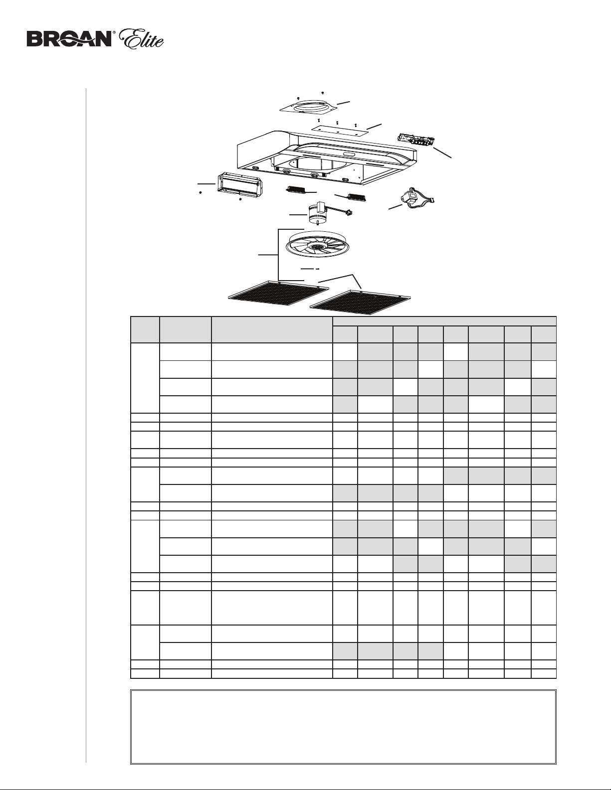
SÉRIE ALT2
C
B
K
MANUEL D’INSTALLATION
2222
D
I
E
F
G
REPÈRE Nº DE PIÈCE DESCRIPTION
P
S97020029
S97020030
1
S97020031
S98011873
2 SR680508 P
3 S97020534 ADAPTATEUR/VOLET 3¼ PO X 10 PO (INCL. VIS)1 1 111 1 11
4 S97020409
5 S97020407 H
6 SR99420635 C
S99010431-002
7
S99010431-003
8 S97020444 M
9 S97020445 T
S97020431
10
S97020432
S97020433
* S97020452 F
* S98011637 C
* S97020360
S97020466
*
S97020467
* S99527587 C
* S97020470 ENS. D’INST. EASY INSTALL (INCL. VISSERIE)1 1 111 1 1 1
* ARTICLE NON ILLUSTRÉ
LAQUE DE GRILLE DE RECIRCULATION,
NOIRE (INCLUANT LES VIS)
LAQUE DE GRILLE DE RECIRCULATION,
P
BLANCHE (INCLUANT LES VIS)
LAQUE DE GRILLE DE RECIRCULATION, INOX.
P
(INCLUANT LES VIS)
LAQUE DE GRILLE DE RECIRCULATION, INOX.
P
NOIR (INCLUANT LES VIS)
LAQUE POUR CONDUIT ROND DE 7 PO (INCL. VIS)1 1 111 1 1 1
OTEUR DU VENTILATEUR
M
(INCLUANT 4 VIS ET 1 CONDENSATEUR)
ÉLICE (INCLUANT LE REPÈRE 6) 1 1 1 1 1 1 1 1
LIP D’HÉLICE 1 1 111 1 1 1
ILTRE À GRAISSES À MAILLAGE FIN - MOTIFS
F
OBLONGS -TYPE C3 (ENS. DE 2)
FILTRE À GRAISSES À MAILLAGE FIN - MOTIFS
OBLONGS -TYPE D3 (ENS. DE 2)
ODULE DEL (PAIRE) 1 1 111 1 1 1
RANSFORMATEUR 24 V 18 VA (AVEC VIS)1 1 111 1 1 1
C
OMMANDE CAPACITIVE À TOUCHES DEL,
I
NOX. (AVEC VIS)
OMMANDE CAPACITIVE À TOUCHES DEL,
C
B
LANCHE (AVEC VIS)
OMMANDE CAPACITIVE À TOUCHES DEL,
C
NOIRE (AVEC VIS)
AISCEAU DE FILS 1 1 111 1 1 1
OUVERCLE DU COMPARTIMENT ÉLECTRIQUE 1 1 111 1 1 1
AC DE PIÈCES COMPRENANT : 4 VIS À MÉTAUX
S
° 8-18 X 1/2 PO, 6 VIS À BOIS À TÊTE
N
RONDE N° 8 X 5/8 PO, 6 VIS À TÊTE FRAISÉE
° 8 X 1/2 PO
N
ILTRES DE RECIRCULATION - TYPE XC
F
(ENS. DE 2) (INSTAL. SANS CONDUIT SEULEMENT)
ILTRES DE RECIRCULATION - TYPE XD
F
(ENS. DE 2) (INSTAL. SANS CONDUIT SEULEMENT)
LIPS POUR FILTRE AU CHARBON (ENS. DE 4)1 1 111 1 1 1
PIÈCE DE REMPLACEMENT ET SERVICE
PIÈCES DE REMPLACEMENT
Pour assurer le bon fonctionnement de votre appareil, vous devez toujours utiliser des pièces d’origine provenant de Broan-NuTone LLC
ou de Venmar Ventilation ULC. Les pièces d’origine de Broan-NuTone LLC ou de Venmar Ventilation ULC sont spécialement conçues
pour satisfaire toutes les normes de certification de sécurité applicables. Leur remplacement par des pièces ne provenant pas de
Broan-NuTone LLC ou de Venmar Ventilation ULC pourrait ne pas assurer la sécurité de l’appareil, entraîner une réduction sévère des
performances ainsi qu’un risque de défaillance prématurée. Broan-NuTone LLC et Venmar Ventilation ULC recommandent également de
toujours vous référer à une entreprise de services compétente et reconnue par Broan-NuTone LLC ou Venmar Ventilation ULC pour vos
pièces de remplacement et appels de service.
30 PO
N
J
H
QUANTITÉ
30 PO
OIR
INOX. NOIR
11
11
1 1 111 1 1 1
1111
11 11
1 1 111 1 1 1
1 1 111 1 1 1
30
30 PO
NOX.
I
PO
36 PO
BLANC
11
11
11
11
36 PO
OIR
INOX. NOIR
N
1111
1111
36 PO
NOX.
I
36
PO
BLANC

SÉRIE ALT1
D
C
B
J
E
I
F
G
H
REPÈRE Nº DE PIÈCE DESCRIPTION
S97020029 P
S97020030 P
1
S97020031 P
2 SR680508 P
3 S97020534 A
4 S97020408 M
5 S97020407 H
6 SR99420635 C
S99010434-002 F
7
S99010434-003 F
S99030367 I
S99030355 I
8
S99030356 I
9 SV05921 A
* S97020448 F
* S98011637 C
* S97020292
S97020466
*
S97020467
* S99527587 C
* S97020470 E
* ARTICLE NON ILLUSTRÉ.
LAQUE DE GRILLE DE RECIRCULATION, NOIRE (INCL. LES VIS)1 1
LAQUE DE GRILLE DE RECIRCULATION, BLANCHE (INCL. LES VIS)1 1
LAQUE DE GRILLE DE RECIRCULATION, INOX. (INCLUANT LES VIS)1 1
LAQUE POUR CONDUIT ROND DE 7 PO (INCLUANT LES VIS) 111111
DAPTATEUR/VOLET DE 3¼ PO X 10 PO (INCLUANT LES VIS) 111111
OTEUR DU VENTILATEUR (INCL. 4 VIS ET 1 CONDENSATEUR)111111
ÉLICE (INCLUANT LE REPÈRE 6) 111111
LIP D’HÉLICE 111111
ILTRE À GRAISSES À MAILLAGE FIN -TYPE C2 (ENSEMBLE DE 2)111
ILTRE À GRAISSES À MAILLAGE FIN -TYPE D2 (ENSEMBLE DE 2) 111
NTERRUPTEUR À BASCULE, GRIS (ENSEMBLE DE)11
NTERRUPTEUR À BASCULE, BLANC (ENSEMBLE DE)11
NTERRUPTEUR À BASCULE, NOIR (ENSEMBLE DE 2) 1 1
MPOULE HALOGÈNE AVEC ÉCRAN 50 W, GU10 2 2 2 2 2 2
AISCEAU DE FILS 111111
OUVERCLE DU COMPARTIMENT ÉLECTRIQUE 111111
S
AC DE PIÈCES COMPRENANT : 4 VIS À MÉTAUX N° 8-18 X 1/2 PO,
VIS À BOIS À TÊTE RONDE N° 8 X 5/8 PO, 6 VIS À TÊTE FRAISÉE
6
N° 8 X 1/2 PO, 1 VENTOUSE
ILTRES DE RECIRCULATION - TYPE XC (ENSEMBLE DE 2)
F
(
INSTALLATION SANS CONDUIT SEULEMENT)
ILTRES DE RECIRCULATION - TYPE XD (ENSEMBLE DE 2)
F
INSTALLATION SANS CONDUIT SEULEMENT)
(
LIPS POUR FILTRE AU CHARBON (ENSEMBLE DE 4) 111111
NSEMBLE D’INSTALLATION EASY INSTALL (INCL. LA VISSERIE)111111
NOX.
QUANTITÉ
PO
30
BLANC
36 PO
36 PO
I
NOIR
NOX.
111
PO
36
BLANC
30 PO
30 PO
I
NOIR
111111
111
PIÈCES DE REMPLACEMENT
MANUEL D’INSTALLATION
PIÈCE DE REMPLACEMENT ET SERVICE
Pour assurer le bon fonctionnement de votre appareil, vous devez toujours utiliser des pièces d’origine provenant de Broan-NuTone LLC.
Les pièces d’origine de Broan-NuTone LLC sont spécialement conçues pour satisfaire toutes les normes de certification de sécurité
applicables. Leur remplacement par des pièces ne provenant pas de Broan-NuTone LLC pourrait ne pas assurer la sécurité de l’appareil,
entraîner une réduction sévère des performances ainsi qu’un risque de défaillance prématurée. Broan-NuTone LLC recommande
également de toujours vous référer à une entreprise de services compétente et reconnue par Broan-NuTone LLC pour vos pièces de
remplacement et appels de service.
2323

MANUEL D’INSTALLATION
2424
Période de garantie et exclusions : Broan NuTone LLC (la « Société ») ou Venmar Ventilation ULC et/ou son subsidiaire garantit
au consommateur acheteur initial (« vous ») de son produit (le « Produit ») que celui-ci est exempt de tout vice de matériau ou de fabrication
pour une période de un (1) an à compter de la date d’achat originale (ou toute période plus longue que pourrait exiger une loi applicable).
Pour les hottes munies de modules à DEL intégrés, la Société garantit que les modules à DEL ainsi que le module d’alimentation
DEL sont exempts de tout vice de matériau pour une période de trois (3) ans. La période de la garantie limitée sur toute pièce de
remplacement fournie par la Société et sur tout produit réparé ou remplacé en vertu de la présente garantie limitée correspond au
reste de la période de garantie originale (ou toute période plus longue que pourrait exiger une loi applicable).
La présente garantie ne s’applique pas aux tubes uorescents et aux démarreurs, ni aux ampoules halogènes ou incandescentes,
fusibles, ltres, conduits, capuchons de toit, capuchons muraux et autres accessoires pour conduits pouvant avoir été achetés
séparément et installés avec le produit. La présente garantie ne couvre pas (a) les travaux d’entretien et de service normaux,
(b) l’usure normale, (c) tout produit ou toute pièce ayant fait l’objet d’une mauvaise utilisation, d’un abus, d’un usage anormal,
d’une négligence, d’un accident, d’un entretien, rangement ou réparation inadéquats ou insuf sants (autre que par la Société),
(d) les dommages dus à une mauvaise installation, ou à une installation ou utilisation contraires aux recommandations ou
instructions, (e) tout produit déplacé de son lieu d’installation original, (f) les dommages dus à des éléments environnementaux
ou naturels, (g) les dommages dus au transport, (h) l’usure naturelle du ni, (i) les produits utilisés à des ns commerciales ou
non-résidentielles ou (j) les dommages dus à un incendie, à une inondation ou à un événement fortuit, (k) les produits dont les
numéros de série ont été altérés, rendus illisibles ou enlevés. La présente garantie ne couvre que les produits vendus au consommateur
initial aux États-Unis et au Canada par la Société ou par les distributeurs américains et canadiens autorisés par la Société.
La présente garantie remplace toute garantie précédente et le consommateur et acheteur initial ne peut la céder à quiconque.
Aucune autre garantie : La présente garantie limitée stipule les seules obligations de la Société et votre seul recours en cas
de produits défectueux. La garantie ci-dessus est exclusive et remplace toute autre garantie, expresse ou tacite. LA SOCIÉTÉ
EXCLUT TOUTE AUTRE GARANTIE OU CONDITION EXPRESSE ET TOUTE GARANTIE OU CONDITION DÉCOULANT
IMPLICITEMENT DE LA LOI, Y COMPRIS, SANS S’Y LIMITER, LES GARANTIES DE VALEUR MARCHANDE ET
D’ADÉQUATION À UN USAGE PARTICULIER. Dans la mesure où la loi en vigueur interdit l’exclusion des garanties tacites ou
conditions, la durée de toute garantie tacite est limitée à la période stipulée ci-dessus pour la garantie expresse. Certains territoires
ou provinces interdisant de limiter la durée d’une garantie tacite, la limitation ci-dessus peut ne pas s’appliquer à votre situation.
Toute description verbale ou écrite du produit a pour seule n de l’identi er et ne doit pas être interprétée comme une garantie expresse.
Si possible, chaque disposition de cette garantie limitée doit être interprétée de sorte à être en vigueur et valide en vertu des
lois applicables, mais si une disposition s’avère interdite ou invalide, elle le sera seulement dans la mesure de cette interdiction
ou invalidité, sans invalider le reste de cette disposition ni les autres dispositions de la présente garantie limitée.
Recours : Pendant la période de garantie limitée applicable, la Société pourra, à son choix, fournir des pièces de rechange
ou réparer ou remplacer, sans frais, tout produit ou toute pièce, dans la mesure où la Société constate qu’il est couvert et
contrevient à la présente garantie limitée dans des conditions normales d’utilisation et de service. La Société vous enverra
gratuitement le produit réparé ou remplacé ou les pièces de rechange. Vous êtes responsable des frais de démontage, de
remontage, d’expédition, d’assurance ou de tous autres frais de transport pour l’envoi du produit ou de la pièce à la Société. Si
vous devez envoyer le produit ou la pièce à la Société, tel que la Société vous l’indiquera, vous devrez l’emballer correctement.
La Société n’est pas responsable des dommages subis lors du transport. La Société se réserve le droit d’utiliser des produits ou
des pièces remis en état, remis à neuf, réparés ou réusinés dans le processus de réparation ou de remplacement sous garantie.
Lesdits produits ou pièces seront comparables en fonction et en performance aux produits et pièces d’origine et seront garantis
pendant le reste de la période de garantie originale (ou toute période plus longue que pourrait exiger une loi applicable).
La Société se réserve le droit, à son entière discrétion, de vous rembourser le prix que vous avez payé pour votre produit en lieu et place
d’une réparation ou d’un remplacement. Si le produit ou le composant n’est plus offert, il sera remplacé par un produit de valeur égale
ou supérieure, à l’entière discrétion de la Société. Cette mesure constitue votre recours exclusif en cas de violation de cette garantie limitée.
Exclusion de dommages : L’OBLIGATION DE LA SOCIÉTÉ DE FOURNIR DES PIÈCES DE RECHANGE, OU DE RÉPARER
OU REMPLACER LE PRODUIT, À SON CHOIX, CONSTITUE VOTRE SEUL ET UNIQUE RECOURS EN VERTU DE LA
PRÉSENTE GARANTIE LIMITÉE ET LA SEULE ET UNIQUE OBLIGATION DE LA SOCIÉTÉ. LA SOCIÉTÉ NE PEUT ÊTRE
TENUE RESPONSABLE DE TOUT DOMMAGE INDIRECT, CONSÉCUTIF, ACCESSOIRE OU SPÉCIAL DÉCOULANT DE
L’UTILISATION OU DU RENDEMENT DU PRODUIT. Les dommages accessoires comprennent, sans pour autant y être limités,
la perte de temps et la privation de jouissance. Les dommages indirects comprennent, sans pour autant y être limités, le coût de
réparation ou de remplacement des autres biens endommagés par le mauvais fonctionnement du produit.
LA SOCIÉTÉ NE POURRA ÊTRE TENUE RESPONSABLE EN RIEN, NI À TOUTES PERSONNES, DE TOUTE OBLIGATION OU
RESPONSABILITÉ INCLUANT SANS S’Y LIMITER, LES OBLIGATIONS OU RESPONSABILITÉS ÉMANANT D’UN BRIS DE
CONTRAT OU D’UNE VIOLATION DE GARANTIE, LA NÉGLIGENCE OU AUTRE FORME DE PRÉJUDICE, OU TOUT AUTRE THÉORIE
DE STRICTE RESPONSABILITÉ CONCERNANT LE PRODUIT, LES ACTIONS, OMISSIONS OU AUTRE DE LA SOCIÉTÉ.
Certains territoires ou provinces ne permettant pas la limitation ou l’exclusion des dommages indirects ou consécutifs, la limitation
ci-dessus peut ne pas s’appliquer à votre situation. La présente garantie vous confère des droits spéci ques reconnus par la loi.
D’autres droits pourraient également vous être accordés selon la législation locale en vigueur.
La présente garantie ne couvre que le remplacement ou la réparation des produits ou pièces défectueux à l’usine principale de la
Société et ne comprend pas les frais de voyage et ni les dépenses quotidiennes pour une réparation à domicile.
Toute aide que la Société vous fournit en dehors des dispositions, limitations ou exclusions de cette garantie limitée ne constituera
en rien une renonciation auxdites dispositions, limitations ou exclusions, et ne prolongera aucunement cette garantie pas plus
qu’elle ne la remettra en vigueur. Les conditions, exclusions et les limitations de responsabilités au titre de la présente garantie ne
s’appliqueront pas dans la mesure où toute loi applicable l’interdit.
La Société ne vous remboursera aucune dépense encourue par vous pour la réparation ou le remplacement de tout produit
défectueux, sauf celles que vous avez encourues avec la permission écrite préalable de la Société.
Comment bénéfi cier du service de garantie : Pour vous prévaloir de cette garantie, vous devez (a) aviser la Société à l’adresse
GARANTIE
ou au numéro de téléphone indiqués ci-dessous dans les sept (7) jours du constat de la défectuosité couverte, (b) donner le
numéro de modèle du produit et le numéro d’identi cation de la pièce et (c) décrire la nature de la défectuosité du produit ou de
la pièce. Lors de votre demande de garantie, vous devez présenter une preuve de la date d’achat originale. Si vous ne pouvez pas
fournir une copie écrite de la garantie limitée originale, les dispositions de la garantie limitée écrite la plus récente de la Société
concernant ce produit particulier s’appliqueront. Vous trouverez les garanties limitées écrites les plus récentes des produits
Société sur les sites www.broan.com et www.broan.ca.
Broan-NuTone LLC 926 West State Street, Hartford, WI 53027 www.broan.com 800-637-1453
Venmar Ventilation ULC, 550 boul. Lemire, Drummondville, Québec, Canada J2C 7W9 www.broan.ca 1 877 896-1119
Garantie limitée
de la

WWW.BROAN.COM
WWW.BROAN.CA
CAMPANA
DE COCINA
Series: ALT1 y ALT2
MANUAL DE INSTALACIÓN,
USO Y CUIDADO
Número de serie:
99046182A

Seguridad . . . . . . . . . . . . . . . . . . . . . . . . . . . . . . 3-4
Funcionamiento . . . . . . . . . . . . . . . . . . . . . . . . . . 5
Limpieza y mantenimiento . . . . . . . . . . . . . . . . . 6
Motor
Filtros de grasa
Filtros de recirculación
Hélice
Limpieza del acero inoxidable
Limpieza de acabados pintados
Instalación . . . . . . . . . . . . . . . . . . . . . . . . . . . . 7-20
Herramientas y accesorios recomendados
para la instalación . . . . . . . . . . . . . . . . . . . . . . . 7
Instale los conductos
(instalaciones con conductos únicamente) . . . . 7
Contenido . . . . . . . . . . . . . . . . . . . . . . . . . . . . . 8
Prepare la campana . . . . . . . . . . . . . . . . . . . . . 9-11
Prepare la ubicación de la campana . . . . . . . . . 12
Instalación EZ1 por una persona . . . . . . . . . . 12-14
Instale la campana (soporte EZ1) . . . . . . . . . 15-16
Instalación normal . . . . . . . . . . . . . . . . . . . . . 17
Instale la campana (instalación normal) . . . . 18
Conecte el cableado . . . . . . . . . . . . . . . . . . . . . 19
Instale las bombillas
(serie ALT1 únicamente) . . . . . . . . . . . . . . . . . . 20
Instale los filtros . . . . . . . . . . . . . . . . . . . . . . . . 20
MANUAL DE INSTALACIÓN
ÍNDICE
22
Diagramas de cableado . . . . . . . . . . . . . . . . . . 21
Piezas de repuesto . . . . . . . . . . . . . . . . . . . . 22-23
Garantía . . . . . . . . . . . . . . . . . . . . . . . . . . . . . . . 24

LEA ESTAS INSTRUCCIONNES Y GUÁRDELAS
!
Exclusivamente para cocinas domésticas
!
INSTALADOR: ENTREGUE ESTE MANUAL AL PROPIETARIO.
En EE.UU., registre su campana de cocina en línea en www.broan.com
En Canadá, registre su campana de cocina en línea en www.broan.ca
!
ADVERTENCIA
PARA REDUCIR EL RIESGO DE INCENDIO, DESCARGA ELÉCTRICA O
LESIÓN CORPORAL, RESPETE LAS SIGUIENTES INDICACIONE:
• Utilice esta unidad únicamente de la forma en que indica el fabricante.
Si tiene cualquier pregunta, póngase en contacto con el fabricante en la
dirección o el teléfono que aparecen en la garantía.
• Antes de reparar o limpiar el aparato, apáguelo en el tablero de servicio
y bloquee los medios de desconexión para impedir que la corriente se
conecte accidentalmente. Cuando no se pueda bloquear los medios de
desconexión, coloque un dispositivo de advertencia visible (como una
etiqueta) en el tablero de servicio.
• La instalación y la conexión eléctrica deben ser realizadas por personal
calificado de acuerdo con todos los códigos y normas aplicables, incluso
los relativos a la construcción ignífuga.
• Para lograr una combustión adecuada y una extracción correcta de los
gases a través de la salida del humo (chimenea) del equipo quemador
de combustible — evitando así el contratiro — es necesario disponer
de aire suficiente. Siga las directrices del fabricante del equipo de
material térmico y las normas de seguridad, como las que publica la
NFPA (asociación de protección contra los incendios) y la ASHRAE
(sociedad estadounidense de técnicos de calefacción, refrigeración y aire
acondicionado) así como los códigos de los organismos responsables
locales.
• Al cortar o perforar la pared o el techo, procure no dañar el cableado
eléctrico ni otras instalaciones de servicios públicos.
• Los ventiladores entubados siempre deben tener salida al exterior.
• No use esta unidad con ningún otro control de velocidad de estado sólido.
• Para reducir el riesgo de incendio, utilice sólo tuberías metálicas.
• Este aparato debe conectarse a tierra.
• Como alternativa, se puede instalar este producto con el juego de cable
de alimentación aprobado por UL y diseñado para el producto, siguiendo
las instrucciones incluidas con el cable.
• Cuando une reglamentación local esta en vigor y conlleva exigencias
de instalación y/o de certificación mas estrictas, susodichas exigencias
prevalecen sobre aquellas en este documento y el instalador acepta
someterse a estas exigencias a sus gastos.
SEGURIDAD
MANUAL DE INSTALACIÓN
33

!
ADVERTENCIA
PARA REDUCIR EL RIESGO DE QUE ARDA LA GRASA EN LA PARTE
SUPERIOR DE LA COCINA:
a) No deje nunca recipientes de cocina a fuego vivo sin vigilancia. Los
desbordamientos producen humo y derrames grasientos que pueden inflamarse.
Caliente el aceite despacio, a fuego lento o mediano..
b) Ponga en marcha siempre la campana extractora al cocinar a temperaturas
elevadas o al cocinar alimentos flameados (crepas Suzette, cerezas jubilee, res
con pimienta flambeada).
c) Limpie el ventilador con frecuencia. No deje que la grasa se acumule en el
ventilador, ni en los filtros o en los conductos de evacuación.
d) Utilice cacerolas de tamaño apropiado. Emplee siempre un recipiente adecuado
para el tamaño de la placa..
PARA REDUCIR EL RIESGO DE LESIONES CORPORALES EN EL CASO
DE QUE ARDA LA GRASA EN LA PARTE SUPERIOR DE LA COCINA,
SIGA ESTAS INDICACIONES*:
1. SOFOQUE LAS LLAMAS con una tapa ajustada, una hoja o bandeja metálica
para hornear galletas, y apague luego el quemador. TENGA CUIDADO PARA
EVITAR QUEMADURAS. SI LAS LLAMAS NO SE APAGAN INMEDIATAMENTE,
EVACUE EL LUGAR Y LLAME A LOS BOMBEROS.
2. NO SUJETE NUNCA UNA SARTÉN EN LLAMAS ya que podría quemarse.
3. NO USE AGUA, ni trapos húmedos. Podría causar una violenta explosión de vapor.
4. Utilice un extintor SOLAMENTE si:
A. Tiene un extintor de tipo ABC y sabe usarlo.
B. El incendio es pequeño y está circunscrito a la zona donde empezó.
C. Ya ha llamado a los bomberos.
D. Puede tratar de apagar el fuego si dispone siempre de una salida detrás de usted.
* Fuente: “Kitchen Fire Safety Tips” publicado por la NFPA.
• Sólo para una utilización en el interior.
• Sólo para ventilación general. No debe utilizarse para extraer materiales o vapores peligrosos o
explosivos.
• Para evitar daños en el cojinete del motor y que la hélice haga ruido o se desequilibre, mantenga
la unidad de alimentación lejos de los vaporizadores de pirca, del polvo de la construcción, etc.
• El motor de la campana tiene un dispositivo contra sobrecargas térmicas que apaga el motor
automáticamente si éste se sobrecalienta. El motor volverá a ponerse en marcha cuando se enfríe.
Si el motor sigue apagándose, haga examinarel motor.
• Para lograr una mejor captura de las impurezas producidas al cocinar, la parte inferior de la campana
deberá estar A UN MÍNIMO de 18” y un máximo de 24” sobre el nivel la superficie para cocina.
• Siga siempre las indicaciones del fabricante del equipo de cocina sobre las necesidades de
ventilación.
• Para reducir los riesgos de incendio y extraer el aire debidamente, el aire debe evacuarse fuera.
No extraiga el aire a espacios situados entre las paredes, en el techo o en el desván, falso techo o
garaje.
• Se aconseja llevar anteojos y guantes de seguridad al instalar, reparar o limpiar el aparato.
• Para mayor información y conocer los requisitos, lea la etiqueta con las especificaciones en el
INSTALLATION MANUAL
TABLE OF CONTENTS
MANUAL DE INSTALACIÓN
SEGURIDAD
4
4
producto.
!
PRECAUCIÓN

Funcionamiento
Ponga la campana en marcha siempre antes de empezar a cocinar para crear una corriente
de aire en la cocina. Deje funcionar el ventilador impelente varios minutos para limpiar el aire
cuando ya haya apagado la cocina. De este modo, la cocina estará más limpia y despejada.
La campana funciona así:
SERIE ALT2
BOTÓN DEL VENTILADOR
Cuando el ventilador impelente esté APAGADO, presione este botón para ENCENDER el ventilador
impelente en la última velocidad guardada. Si no se guardó ninguna velocidad, el ventilador se
situará en la velocidad BAJA.
NOTA: Cuando se active la velocidad BAJA a partir del ventilador APAGADO, éste empieza a
funcionar a velocidad MEDIA brevemente y luego pasa a velocidad BAJA.
Para cambiar la velocidad del ventilador impelente, presione de nuevo este botón hasta alcanzar
la velocidad deseada (de velocidad BAJA pasará a MEDIA y luego a ALTA). Si presiona de nuevo
el botón tras la velocidad ALTA, el ventilador se APAGARÁ. Cada vez que se activa la velocidad del
ventilador se oye un pitido y la luz de los indicadores LED se enciende para mostrar la velocidad
elegida correspondiente: LED inferior para velocidad BAJA, LED inferior y central para velocidad
MEDIA y todos los LED para velocidad ALTA.
Cuando el ventilador esté encendido, en cualquier velocidad, mantenga presionada este botón hasta
que acabe el pitido; de este modo, se apagará el ventilador y se guardará la última velocidad.
BOTÓN DE LAS LUCES
Cuando las luces estén apagadas, presione una vez este botón para ENCENDER las luces en la
intensidad que se guardó la última vez. Si no se guardó ninguna intensidad, se encenderán en la
intensidad BAJA. Presione de nuevo el botón para la intensidad ALTA. Si presiona una vez más
con las luces en intensidad ALTA, las luces se apagarán. Cada vez que se encienden las luces,
se oye un pitido y la luz de los indicadores LED se enciende para mostrar la intensidad elegida
correspondiente: LED inferior para intensidad BAJA y ambos LED para intensidad ALTA.
Cuando las luces estén encendidas, independientemente de la intensidad, mantenga presionada este
botón hasta que termine el pitido; de este modo, se apagarán las luces y se guardará la intensidad elegida.
Los módulos LED incluidos con esta campana extractora constituyen la más avanzada tecnología
de iluminación LED de superficies de cocción. Diseñados específicamente para operar a
temperaturas elevadas de cocción, estas luces LED ofrecen una iluminación muy clara, duran
hasta 25 veces más tiempo que los focos estándar y son mucho más fiables que las lámparas
LED de recambio comunes.
RECORDATORIO DE LIMPIEZA DE LOS FILTROS
Cuando todos los indicadores LED del botón del ventilador parpadeen lentamente durante 30 segundos
tras apagar el ventilador, ello significa que ha llegado el momento de limpiar lacampana y los
filtros (consulte la sección Limpieza y mantenimiento en la página 6). Este parpadeo se produce
cada vez que el ventilador está apagado, hasta que el recardatorio de limpieza sea reiniciado. Una
vez terminada la limpieza, reinicie el recordatorio de limpieza de los filtros presionando el botón
del ventilador durante 3 segundos (durante los 30 segundos de parpadeo de los indicatores LED).
SERIE ALT1
FUNCIONAMIENTO
MANUAL DE INSTALACIÓN
INTERRUPTOR DEL VENTILADOR
I Pone en marcha el ventilador a BAJA velocidad.
• APAGA el ventilador.
II Pone en marcha el ventilador a ALTA velocidad.
INTERRUPTOR DE LA LUZ
I Enciende la luz a BAJA intensidad.
• APAGA la luz.
II Enciende la luz a ALTA intensidad.
55

Limpieza y mantenimiento
El mantenimiento adecuado de la campana permitirá que funcione correctamente.
MOTOR
El motor está lubricado permanentemente y no necesita engrase nunca. Si los rodamientos del
motor hacen un ruido excesivo o no habitual, sustituya el motor por otro idéntico. También se
debería sustituir la hélice.
FILTROS DE GRASA
Los filtros de grasa deberían limpiarse con frecuencia. Use una disolución de agua tibia y
detergente para vajilla. Los filtros de grasa se pueden lavar en el lavaplatos.
Lave los filtros metálicos en el lavaplatos con un detergente sin fosfato. Los filtros de pueden
descolorar si se lavan con detergentes con fosfato o debido a las características del agua local
pero esto no afecta su desempeño. Esta descoloración no está cubierta por la garantía. A fin de
reducir al mínimo o prevenir la descoloración, lave los filtros a mano con un detergente suave.
FILTROS DE RECIRCULACIÓN
Los filtros de recirculación deberían cambiarse cada 3 a 6 meses. Sustitúyalo con mayor
frecuencia si su tipo de cocina genera más grasa, por ejemplo si fríe o cocina con wok. Consulte
las instrucciones de instalación que vienen con el filtro de recirculación.
HÉLICE
La hélice debería limpiarse con frecuencia. Use un trapo limpio empapado con una disolución de
agua tibia y detergente.
LIMPIEZA DEL ACERO INOXIDABLE
A hacer:
• Lávelo regularmente con un trapo limpio empapado con una disolución de agua tibia y jabón
suave o detergente para lavar vajillas.
• Limpie siempre en la dirección de las líneas de pulido.
• Enjuague siempre bien con agua limpia (2 o 3 veces) después de limpiar. Séquelo completamente.
• También puede usar un producto limpiador doméstico para acero inoxidable.
A no hacer:
• Usar lana de acero o de acero inoxidable o un rascador para quitar la suciedad más incrustada.
• Usar productos limpiadores agresivos o abrasivos.
• Dejar que se acumule la suciedad.
• Permitir que el polvo de yeso u otros residuos de construcción entren en contacto con la
campana. Durante los trabajos de construcción o renovación, cubra la campana para evitar
que el polvo se adhiera a las superficies de acero inoxidable.
Al elegir un detergente, evite:
• Los productos limpiadores que contengan blanqueador (lejía) ya que dañarán el acero inoxidable.
• Los productos que contengan: cloruro, fluoruro, yoduro, bromuro, ya que deteriorarán las
superficies rápidamente.
• Los productos combustibles que se usan para limpiar, tales como: acetona, alcohol, éter,
benzol, etc., ya que son muy explosivos y no deberían usarse nunca cerca de una cocina.
MANUAL DE INSTALACIÓN
LIMPIEZA Y MANTENIMIENTO
LIMPIEZA DE ACABADOS PINTADOS:
Limpie con agua tibia y un detergente suave únicamente. Si la superficie se descolora, use una
cera para acabados, como una cera para automóviles. (NO use productos limpiadores duros o
abrasivos ni limpiadores para porcelana.)
66

Para las directrices de instalación conforme a la ADA, visite www.broan.com
Herramientas y accesorios recomendados
para la instalación
• Cinta métrica
• Destornillador Phillips n.° 2
• Destornillador de punta plana (para abrir los orificios punzonados)
• Taladro, broca de 1/8” y serrucho de calar de 1½” (para cortar el orificio de acceso del cableado
eléctrico)
• Broca de 7/64” (para taladrar orificios para los tornillos de montaje de los soportes EZ1)
• Calzos de madera (2) y tornillos para madera (4) (necesarios para la instalación en armario
de cocina con armazón)
• Sierra (para cortar orificios para aplicaciones con conductos)
• Cizalla (para instalaciones con conductos únicamente, para ajustar los conductos)
• Alicates (para instalaciones con conductos únicamente, para ajustar los conductos)
• Cinta adhesiva metálica (para aplicaciones con conductos)
• Tijeras (para cortar la cinta adhesiva metálica)
• Lápiz
• Desforrador de hilos
• Descarga de presión, de 1/2” de diámetro (para sujetar el cableado de la vivienda a la campana)
Instale los conductos
(instalaciones canalizadas únicamente
CAPUCHÓN PARA TEJADO
INTRADÓS
ARMARIO
CAMPANA
18” MÍN - 24” MÁX POR ENCIMA
DE
LA SUPERFICIE DE LA COCINA
NOTA: Las distancias superiores a 24” son a discreción del instalador y del usuario.
1 ] Determine si la campana evacuará verticalmente (conducto redondo de 3¼” x 10” o 7”) u
horizontalmente (conducto de 3¼” x 10” únicamente).
2 ] Decida por dónde pasarán los conductos entre la campana y el exterior.
3 ] Elija un paso recto y corto para que la campana funcione de la forma más eficaz. Los recorridos
largos, los codos y las transiciones reducen el desempeño de la campana. Use los menos
posible. Cuando pueda, prevea al menos 2 pies de conducto recto antes de cualquier giro.
Pueden ser necesarios conductos más anchos para lograr mejor desempeño cuando los
conductos más largos giran.
NOTA: Para utilizar conducto redondo de 6”, instale un adaptador de 3¼” x 10” a redondo de 6”
(no incluido). El rendimiento puede verse afectado.
4 ] Instale un capuchón mural o un capuchón para tejado (se venden por separado). Conecte el
conducto metálico al capuchón y vuelva al lugar donde se encuentra la campana. Use cinta
adhesiva metálica de 2” para sellar las juntas entre los tramos de los conductos.
CONDUCTO DE 3¼” X 10”
O 7” REDONDO
(PARA EVACUACIÓN VERTICAL)
CABLEADO DE LA VIVIENDA
(PARTE SUPERIOR OR TRASERA
LA CAMPANA)
DE
CAPUCHÓN MURAL
CONDUCTO DE 3¼” X 10”
(PARA EVACUACIÓN HORIZONTAL)
INSTALACÍON
MANUAL DE INSTALACIÓN
77

Contenido
VERTICAL EXHAUST
Antes empezar la instalación, verifique el contenido de la caja. Si faltan elementos o hay
elementos dañados, póngase en contacto con el fabricante.
Compruebe que estén en la caja los siguientes elementos:
Serie ALT2 Serie ALT1
* SE ENCUENTRA DENTRO
LA CAMPANA
DE
(1) CONJUNTO DE LA
C
L
7½”
10½”
Appuyer ce bord au mur arrière
CLAPETA
OMPONENTES EZ1
C
MARKWHEREINDICATED
FORTHEAPPROPRIATESIZE DUCTOPENING
RECTANGULAR DUCTING7” ROUND DUCTING
OR
= 3¼” x 10”
= 3¼” x 14”
MARQUERLESREPÈRES AUX ENDROITS INDIQUÉS SELON
LEFORMATDECONDUIT UTILISÉ
CONDUITRECTANGULAIRECONDUITRONDDE 7 PO
OU
= 3¼ po x 10 po
= 3¼ po x 14 po
TITLETOBE TRANSLATED IN SPANISH
CONDUCTORECTANGULARCONDUCTOREDONDO
O
= 3¼ pulg. x 10 pulg.
7 PULG.
DE
= 3¼ pulg. x 14 pulg.
Electrical access hole center
A = single blower hood
B = double blower hood
Centre du trou pour fil
d’alimentation électrique
A = hotte ventilateur simple
B = hotte ventilateur double
To be translated in Spanish
Electrical access hole center
4¼”
A = single blower hood
B = double blower hood
AB
C
Apoyar este borde contra la pared de atrásPlace this edge against back wall
DE 3¼” X 10”
(2) F
ILTROS DE GRASA
Use this template for marking;do not attempt to cut out the ducting hole through it.
NOTE: These cutouts are clearance holes; they do not need to be the exact size of ducting.
Utiliser ce gabarit pour marquer vos repères;ne pas tenter de découper
le trou pour le conduit à travers le gabarit.
NOTE : Les découpes incluent le jeu nécessaire à l’installation; elles ne doivent pas
être du format exact des conduits.
Use esta plantilla para crear marcados;no trate de cortar el
agujero del conducto a través de la plantilla.
NOTA: To be translated in Spanish.
Bend template along graduated
scale when installing to framed
cabinet.
C
Pour une installation sous une
armoire à fond en retrait, utiliser les
lignes pour mesurer l’épaisseur du
décalage causé par le mur de
l’armoire et plier le gabarit en
conséquence.
To be translated in Spanish.
C
8”
14½”
** LOS SOPORTES EZ1 ESTÁN DENTRO DE LA CAMPANA
(1) BOLSA DE PIEZAS*** CONTENIDO:
(6) T
ORNILLOS DE CABEZA
REDONDA
PARA MADERA
N
° 8 X 5/8”
*** LA BOLSA DE PIEZAS ESTÁ DETRÁS DEL CONJUNTO
DE LA CLAPETA DE RETENCIÓN
DE RETENCIÓN
(1) PLANTILLA PARA INSTALACIÓN
(IMPRESA POR AMBOS LADOS)
(2) SOPORTES DE INSTALACIÓN**
PARA ARMARIOS CON ARMAZÓN
(2) SOPORTES DE INSTALACIÓN**
PARA ARMARIOS SIN ARMAZÓN
ORNILLOS PARA METAL
(4) T
N
° 8-18 X 1/2”
*
DE
CONDUCTOS
(1) CONECTOR
DE
CONDUCTO
REDONDO
(6) T
EMBUDITOS
PARA
N
° 8 X 1/2”
, DENTRO DE LA CAMPANA
DE
ORNILLOS
MADERA
(2) BOMBILLAS HALÓGENAS
CON
ILTROS DE GRASA
7”
(2) F
(1) CONECTOR
DE
CONDUCTO
REDONDO
DE 7”
PANTALLA 50 W, GU10
* SE ENCUENTRA DENTRO DE LA CAMPANA
(1) CONJUNTO DE LA CLAPETA
DE
RETENCIÓN* DE 3¼” X 10”
COMPONENTES EZ1
Use this template for marking; do not attempt to cut out the ducting hole through it.
NOTE: These cutouts are clearance holes; they do not need to be the exact size of ducting.
Utiliser ce gabarit pour marquer vos repères; ne pas tenter de découper
le trou pour le conduit à travers le gabarit.
NOTE : Les découpes incluent le jeu nécessaire à l’installation; elles ne doivent pas
être du format exact des conduits.
Use esta plantilla para crear marcados; no trate de cortar el
agujero del conducto a través de la plantilla.
NOTA: To be translated in Spanish.
Bend template along graduated
scale when installing to framed
cabinet.
C
Pour une installation sous une
armoire à fond en retrait, utiliser les
lignes pour mesurer l’épaisseur du
décalage causé par le mur de
l’armoire et plier le gabarit en
8”
conséquence.
To be translated in Spanish.
VERTICAL EXHAUST
C
MARK WHERE INDICATED
FOR THE APPROPRIATE SIZE DUCT OPENING
ECTANGULAR DUCTING
OUND DUCTING
R
7” R
OR
= 3¼” x 10”
= 3¼” x 14”
MARQUER LES REPÈRES AUX ENDROITS INDIQUÉS SELON
LE FORMAT DE CONDUIT UTILISÉ
CONDUIT RECTANGULAIRECONDUIT ROND DE 7 PO
OU
= 3¼ po x 10 po
= 3¼ po x 14 po
TITLE TO BE TRANSLATED IN SPANISH
ONDUCTO RECTANGULARCONDUCTO REDONDO
C
O
= 3¼ pulg. x 10 pulg.
7 PULG.
DE
14½”
Appuyer ce bord au mur arrière
C
L
= 3¼ pulg. x 14 pulg.
(1) PLANTILLA PARA INSTALACIÓN
7½”
10½”
Electrical access hole center
A = single blower hood
B = double blower hood
Centre du trou pour fil
d’alimentation électrique
A = hotte ventilateur simple
B = hotte ventilateur double
To be translated in Spanish
Electrical access hole center
4¼”
A = single blower hood
B = double blower hood
AB
C
Apoyar este borde contra la pared de atrásPlace this edge against back wall
DE
CONDUCTOS
(IMPRESA POR AMBOS LADOS)
(2) S
OPORTES DE INSTALACIÓN**
PARA ARMARIOS CON ARMAZÓN
(2) SOPORTES DE INSTALACIÓN**
PARA ARMARIOS SIN ARMAZÓN
** LOS SOPORTES EZ1 ESTÁN DENTRO DE LA CAMPANA
(1) BOLSA DE PIEZAS*** CONTENIDO:
(4) T
ORNILLOS PARA METAL
N
° 8-18 X 1/2”
(6) T
(6) T
ORNILLOS DE CABEZA
REDONDA
PARA MADERA
N
° 8 X 5/8”
ORNILLOS
EMBUDITOS
PARA
MADERA
N
° 8 X 1/2”
MANUAL DE INSTALACIÓN
88
INSTALACÍON
(1) V
PARA
ENTOSA
BOMBILLAS
*** LA BOLSA DE PIEZAS ESTÁ DETRÁS
DEL CONJUNTO DE CLAPETA DE RETENCIÓN,
DENTRO DE LA CAMPANA

Prepare la campana
NOTA: Dado el gran número de modelos de los que trata este manual, algunos detalles
de su aparato pueden ser ligeramente distintos de los que se muestran aquí.
1 ] De haberla, retire de la campana y de todas las piezas la película protectora.
2 ] Use el orificio de agarre para retirar de la campana los filtros de grasa empujando hacia
abajo e inclinando los filtros hacia fuera .
B
C
3 ] Retire los soportes EZ1 del interior de la campana cortando la tira de amarre. Retire ambos
tornillos que sujetan el conjunto de la clapeta a la campana. Retire el conjunto de la clapeta
del interior de la campana y conserve los tornillos para usarlos posteriormente. Retire la
bolsa de piezas (sujeta detrás del conjunto de la clapeta).
SOPORTES EZ1
B
C
TORNILLOS
CONJUNTO DE
LA CLAPETA
4 ] Retire la tapa del cableado (parte sombreada de la ilustración de abajo) deslizándola fuera
de la campana; póngala a un lado.
INSTALACÍON
MANUAL DE INSTALACIÓN
99

5 ] Retire la placa para conducto redondo de 7” de la parte superior trasera de la campana y
conserve los tornillos para usarlos posteriormente (véase la ilustración de abajo).
PLACA PARA
CONDUCTO
REDONDO
DE 7”
2 TORNILLOS
6 ] Retire la parte punzonada para el cable de alimentación eléctrica desde la parte superior
(cableado vertical) o desde la parte trasera (cableado horizontal) de la campana. Instale una
descarga de presión adecuada de 1/2” de diámetro (no incluida).
PARTE PUNZONADA
PARA EL CABLE DE
ALIMENTACIÓN ELÉCTRICA
MANUAL DE INSTALACIÓN
INSTALACÍON
INSTALACIÓN SIN CONDUCTOS ÚNICAMENTE
7 ] Retire los 3 tornillos que sujetan la placa de cubierta de recirculación (parte sombreada
de la ilustración de abajo) a la campana. Deseche esta placa y los tornillos.
PLACA DE CUBIERTA
DE RECIRCULACIÓN
TORNILLOS
1010
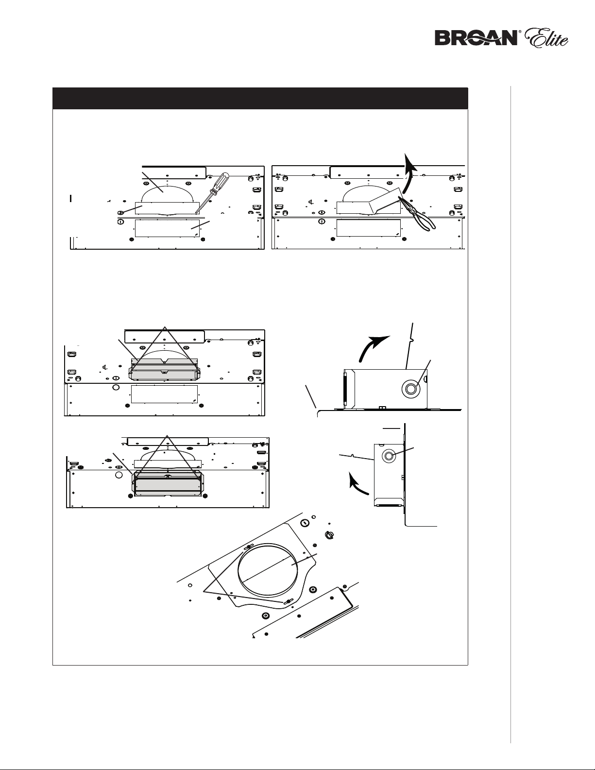
INSTALACIÓN CON CONDUCTOS ÚNICAMENTE
8 ] Retire la placa punzonada vertical de 3¼” x 10”, la placa punzonada horizontal de 3¼” x 10”
o la placa punzonada redonda de 7 pulgadas, según el modo de evacuación elegido
(véanse las Figuras 1 A y 1 B).
FIGURA 1 A
PLACA PUNZONADA
REDONDA DE 7”
(RETIRE TAMBIÉN LA PLACA
PUNZONADA VERTICAL)
PLACA
PUNZONADA
VERTICAL DE
3¼” X 10”
PLACA
PUNZONADA
HORIZONTAL
DE 3¼” X 10”
9 ] Instale el conjunto de la clapeta de 3¼” x 10” en la parte superior O en la parte trasera
de la campana (si se usa el conducto de 3¼” x 10”; parte sombreada de la Figura 2 A
de abajo) o la placa para conducto redondo de 7” (si se usa el conducto redondo de
7 pulgadas, Figura 3) por encima de la abertura punzonada. Una vez instalado, el conjunto
de la clapeta de 3¼” x 10” debe abrirse como se ve en la Figura 2 B.
FIGURA 2 A FIGURA 2 B
CONJUTO DE
LA CLAPETA
DE 3¼” X 10”
TORNILLOS
FIGURA 1 B
BORDE
SUPERIOR
TRASERO DE
LA CAMPANA
PIVOTE DE LA
COMPUERTA
CONJUTO DE
LA CLAPETA
DE 3¼” X 10”
TORNILLOS
FIGURA 3
TORNILLOS
PARTE TRASERA
DE LA CAMPANA
PLACA PARA
CONDUCTO REDONDO
DE 7”
PIVOTE DE LA
COMPUERTA
NOTA: Para adaptarse a un conducto descentrado, la placa para conducto redondo de 7”
puede instalarse hasta 1/2” de cada lado del centro de la campana.
CONSEJO: Introduzca una pequeña longitud de conducto en el conjunto de la clapeta de 3¼” x 10”
(para un conducto rectangular) o en la placa para conducto redondo de 7” (para un
conducto redondo) y selle la junta con cinta adhesiva de aluminio para facilitar la
conexión con los conductos de la vivienda.
INSTALACÍON
MANUAL DE INSTALACIÓN
1111

Prepare la ubicación de la campana
VERTICAL EXHAUST
VERTICAL EXHAUST
NOTA: antes de empezar la instalación, lea todas las etapas de estas instrucciones.
Use la ilustración de abajo para reconocer su tipo de armario de cocina.
ARMARIO CON ARMAZÓN ARMARIO SIN ARMAZÓN
Este manual cubre 2 tipos de instalación: la normal (sin soportes EZ1) y la instalación EZ1 por una
persona (usando la plantilla y los soporte provistos). Para la instalación normal, vaya a la página 17.
Sistema de instalación EZ1 por una persona
La instalación EZ1 está pensada para armarios de cocina que tienen la misma anchura que la de
la campana. Si el armario es 1/2” más ancho que la campana, use el modo de instalación normal.
1 ] Use la plantilla adecuada para la evacuación vertical U horizontal (incluidas) para colocar los conductos
y la alimentación eléctrica en el armario o en la pared. Para una instalación sin conductos,
NO corte el orificio de acceso al conducto; corte sólo el orificio para el cableado eléctrico. Si
sustituye una campana y prevé usar el conducto y la alimentación eléctrica existentes,
puede que las etapas 2 a 5 no sean necesarias. De ser el caso, pase a la etapa 6.
2 ] Mida y marque la línea central de la campana en la parte inferior del armario.
3 ] Alinee la línea central de la plantilla con la línea central de la campana marcada en la parte inferior
del armario, colocando el borde (donde se indica) de la plantilla contra la pared trasera.
Cuando se use un armario con armazón para una instalación con salida vertical, pliegue
hacia atrás el borde de la plantilla en una medida equivalente a la profundidad del armazón
del armario en la pared (use las graduaciones de la plantilla, puntos C de la plantilla). Sujete
la plantilla con cinta adhesiva.
NOTA: Si se sitúa frente a la instalación, A y B (en la plantilla) deben estar a la derecha.
PA RT E
DELANTERA
DEL ARMARIO
Use this template for marking;do not attempt to cut out the ducting hole through it.
NOTE: These cutouts are clearance holes; they do not need to be the exact size of ducting.
Utiliser ce gabarit pour marquer vos repères;ne pas tenter de découper
le trou pour le conduit à travers le gabarit.
NOTE : Les découpes incluent le jeu nécessaire à l’installation; elles ne doivent pas
être du format exact des conduits.
Use esta plantilla para crear marcados;no trate de cortar el
agujero del conducto a través de la plantilla.
NOTA: To be translated in Spanish.
Bend template along graduated
scale when installing to framed
cabinet.
C
Pour une installation sous une
armoire à fond en retrait, utiliser les
lignes pour mesurer l’épaisseur du
décalage causé par le mur de
l’armoire et plier le gabarit en
8”
conséquence.
To be translated in Spanish.
C
C
MARKWHERE INDICATED
FORTHE APPROPRIATE SIZE DUCT OPENING
RECTANGULAR DUCTING7” ROUND DUCTING
OR
= 3¼” x 10”
= 3¼” x 14”
MARQUERLES REPÈRES AUX ENDROITS INDIQUÉSSELON
LEFORMATDE CONDUITUTILISÉ
CONDUITRECTANGULAIRECONDUITROND DE 7 PO
OU
= 3¼ po x 10 po
= 3¼ po x 14 po
TITLETO BE TRANSLATED IN SPANISH
CONDUCTORECTANGULARCONDUCTOREDONDO
O
= 3¼ pulg. x 10 pulg.
DE
C
L
14½”
Appuyer ce bord au mur arrière
7 PULG.
= 3¼ pulg. x 14 pulg.
4¼”
Electrical access hole center
A = single blower hood
B = double blower hood
Centre du trou pour fil
d’alimentation électrique
A = hotte ventilateur simple
B = hotte ventilateur double
To be translated in Spanish
Electrical access hole center
A = single blower hood
B = double blower hood
AB
C
7½”
10½”
Apoyar este borde contra la pared de atrásPlace this edge against back wall
DOBLE LA PLANTILLA A LO LARGO DE LA
ESCALA GRADUADA AL INSTALAR LA CAMPANA
P
EN
UN ARMARIO CON ARMAZÓN
.
PA RT E
DELANTERA
DEL ARMARIO
Use this template for marking;do not attempt to cut out the ducting hole through it.
NOTE: These cutouts are clearance holes; they do not need to be the exact size of ducting.
Utiliser ce gabarit pour marquer vos repères;ne pas tenter de découper
le trou pour le conduit à travers le gabarit.
NOTE : Les découpes incluent le jeu nécessaire à l’installation; elles ne doivent pas
être du format exact des conduits.
Use esta plantilla para crear marcados;no trate de cortar el
agujero del conducto a través de la plantilla.
NOTA: To be translated in Spanish.
Bend template along graduated
scale when installing to framed
cabinet.
C
Pour une installation sous une
armoire à fond en retrait, utiliser les
lignes pour mesurer l’épaisseur du
décalage causé par le mur de
l’armoire et plier le gabarit en
8”
conséquence.
To be translated in Spanish.
C
LÍNEA
CENTRAL
CONDUCTOS DE
SALIDA VERTICAL
MARKWHERE INDICATED
FORTHE APPROPRIATE SIZE DUCT OPENING
RECTANGULAR DUCTING7” ROUND DUCTING
OR
= 3¼” x 10”
= 3¼” x 14”
MARQUERLES REPÈRES AUX ENDROITS INDIQUÉSSELON
LEFORMATDE CONDUITUTILISÉ
CONDUITRECTANGULAIRECONDUITROND DE 7 PO
OU
= 3¼ po x 10 po
= 3¼ po x 14 po
TITLETO BE TRANSLATED IN SPAN IS H
CONDUCTORECTANGULARCONDUCTOREDONDO
O
= 3¼ pulg. x 10 pulg.
DE
C
L
14½”
7 PULG.
= 3¼ pulg. x 14 pulg.
7½”
10½”
Electrical access hole center
A = single blower hood
B = double blower hood
Centre du trou pour fil
d’alimentation électrique
A = hotte ventilateur simple
B = hotte ventilateur double
To be translated in Spanish
Electrical access hole center
4¼”
A = single blower hood
B = double blower hood
AB
C
A
UBICACIÓN DEL
ORIFICIO DE ACCESO
DEL CABLE ELÉCTRICO (A)
C
EN LA PARTE INFERIOR DEL ARMARIO)
(
MANUAL DE INSTALACIÓN
INSTALACÍON
1212
LÍNEA
CENTRAL
Use this template for marking;do not attempt to cut out the ducting hole through it.
NOTE: These cutouts are clearance holes; they do not need to be the exact size of ducting.
Utiliser ce gabarit pour marquer vos repères;ne pas tenter de découper
le trou pour le conduit à travers le gabarit.
NOTE : Les découpes incluent le jeu nécessaire à l’installation; elles ne doivent pas
être du format exact des conduit
s.
Use esta plantilla para crear marcados;no trate de cortar el
agujero del conducto a través de la plantilla.
NOTA: To be translated in Spanish.
Place this edge against
cabinet bottom.
Appuyer ce bord contre le bas
de l’armoire.
Apoyar este borde contra
la base del armario.
C
L
CONDUCTOS DE
SALIDA HORIZONTAL
AB
Electrical access hole center
A = single blower hood
B = double blower hood
Centre du trou pour fil
d’alimentation électrique
A = hotte ventilateur simple
B = hotte ventilateur double
To be translated in Spanish
Electrical access hole center
A = single blower hood
MARKWHEREINDICATED
FORTHEAPPROPRIATE SIZE DUCTOPENING
RECTANGULAR DUCTING
= 3¼” x 10”
= 3¼” x 14”
TITLETOBE TRANSLATEDIN SPANISH
CONDUCTORECTANGULAR
B = double blower hood
MARQUERLESREPÈRES AUXENDROITS INDIQUÉS SELON
LEFORMATDE CONDUIT UTILISÉ
CONDUITRECTANGULAIRE
= 3¼ po x 10 po
= 3¼ po x 14 po
= 3¼ pulg. x 10 pulg.
= 3¼ pulg. x 14 pulg.
ORIFICIO DE ACCESO
DEL CABLE ELÉCTRICO (A)
A
Electrical access hol
A = single blower ho
B = double blower
Centre du tr
d’alim
UBICACIÓN DEL
EN LA PARED)
(
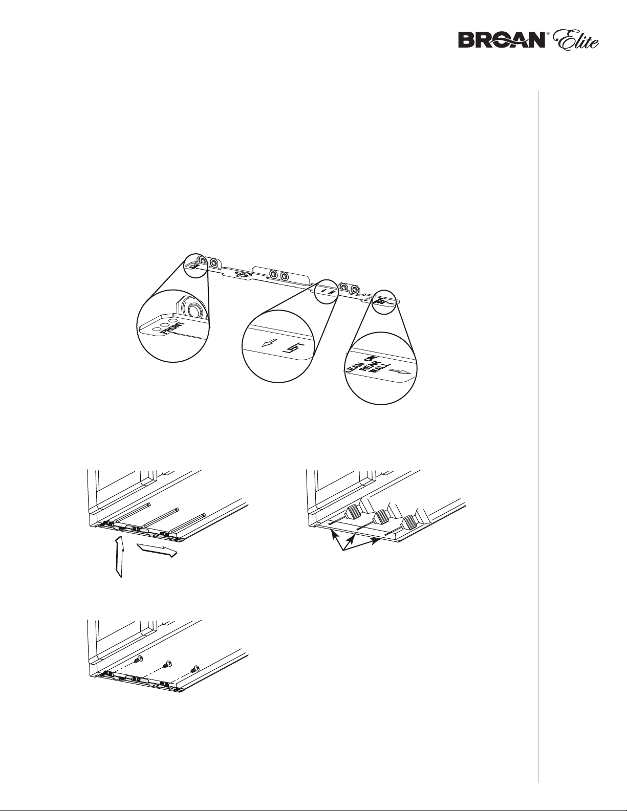
4 ] Taladre un orificio piloto de 1/8” de diámetro para el cableado de la vivienda, en el punto A
de la plantilla.
5 ] Use un lápiz afilado o una broca de 1/8” para marcar los puntos para los orificios de acceso
de los conductos (16 puntos para un conducto redondo de 7”, o 4 puntos en las esquinas
para un conducto rectangular). Retire la plantilla.
6 ] Dibuje el borde de la evacuación de salida uniendo los puntos (16 puntos para un conducto
redondo de 7” y 4 puntos para un conducto rectangular), corte la abertura en la parte inferior
del armario (salida vertical) o en la pared (salida horizontal). Taladre el orificio para el
cableado de la vivienda usando un serrucho de calar de 1½” centrándolo en el orificio piloto
hecho en la etapa 4.
7 ] Instale los soporte de instalación adecuados según el tipo de armario (con armazón o sin
armazón). Véase abajo.
ARMARIO
CON ARMAZÓN
Consulte las marcas de los soporte para establecer el lado y la orientación correctos de la
instalación (marcas en ingles solamente: front = frente, left = izquierda, lean on rear wall =
appoyar contra la pared de atrás).
XY
7/64”
Z
Acople el soporte correspondiente a la armazón lateral del armario colocando la parte
de atrás del soporte contra la pared. Use un lápiz para marcar 3 orificios (hay 6 orificios
pero sólo se necesitan 3).
Retire el soporte. Use una broca de 7/64” para taladrar 3 orificios donde los marcara.
Una el soporte al armazón lateral con un destornillador Phillips y 3 tornillos para
madera no 8 x 9/16” provistos. Repita la operación en el otro lado del armazón.
INSTALACÍON
MANUAL DE INSTALACIÓN
1313

ARMARIO
SIN ARMAZÓN
Consulte las marcas de los soporte para establecer el lado y la orientación correctos de la
instalación (marcas en ingles solamente: front = frente, left = izquierda, lean on rear wall =
appoyar contra la pared de atrás).
X
Y
3 X
Z
[ \
7/64”
Alinee el soporte correspondiente al lado del armario, colocando al mismo tiempo la
parte trasera del soporte contra la pared. Dibuje una línea a lo largo del borde exterior
del soporte (como se muestra).
Coloque el soporte en el centro del armario y alinee el borde lateral con la línea
marcada manteniendo la parte trasera apoyada en la pared.
MANUAL DE INSTALACIÓN
1414
Use un lápiz para marcar 3 orificios.
Retire el soporte. Use una broca de 7/64” para taladrar 3 orificios donde los marcara.
Una el soporte a la parte inferior del armario con un destornillador Phillips y 3 tornillos
embutidos para madera provistos. Repita la operación en el otro lado del armario.
INSTALACÍON
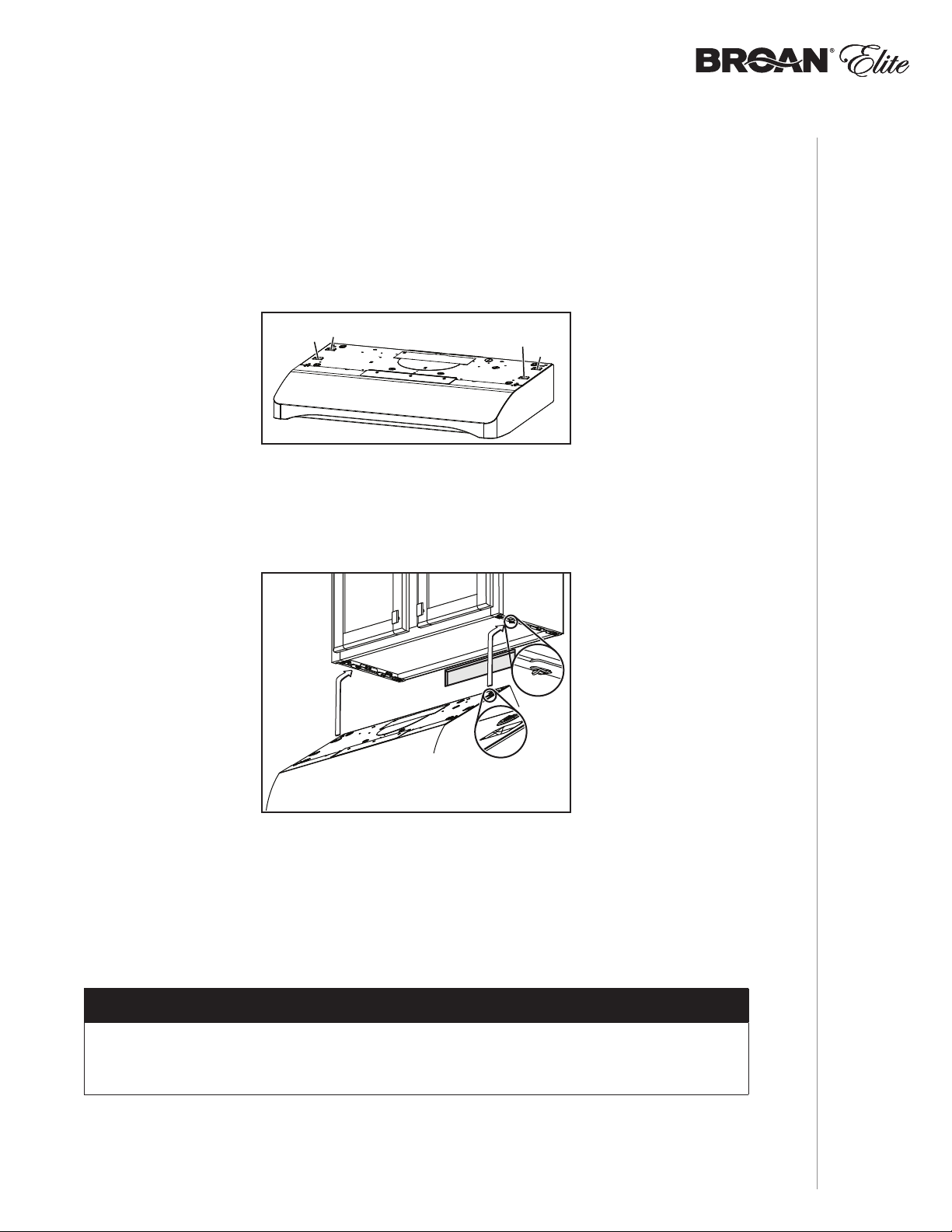
Instale la campana (Soporte EZ1)
OTA: N El procedimiento siguiente se aplica a las instalaciones en armarios con armazón
y sin armazón.
1 ] Lleve el cable de alimentación de la vivienda del tablero de servicio al lugar de la campana.
2 ] Hay 2 pares de orificios rebajados en cada lado de la parte superior de la campana (en la
parte trasera: A y B, en la parte delantera C y D en la ilustración de abajo); estos orificios
permiten colgar la campana a los soportes (instalados previamente).
A
C
INSTALACIÓN CON SALIDA HORIZONTAL
3 ] Cuelgue provisionalmente la campana de los soportes por medio de los dos (2) ORIFICIOS
TRASEROS rebajados (A y B). Mientras sujeta la campana, lleve el cable de alimentación
de la vivienda hasta la campana a través de la descarga de presión instalada previamente
en la etapa 6 en la página 10.
D
B
A
4 ] Desenganche los orificios traseros de los soportes y cuelgue la campana por medio de los
dos (2) ORIFICIOS DELANTEROS rebajados (C y D). Sujete el cable de alimentación a la
campana usando la descarga de presión.
INSTALACIÓN CON SALIDA VERTICAL Y INSTALACIÓN SIN CONDUCTOS
5 ] Cuelgue la campana a los soportes usando los dos (2) ORIFICIOS DELANTEROS rebajados
(C y D). Mientras sujeta la campana, sujete el cable de alimentación a la campana usando
la descarga de presión instalada previamente en la etapa 6 en la página 10.
B
INSTALACIÓN CON CONDUCTOS ÚNICAMENTE
6 ] Conecte los conductos a la campana y use cinta adhesiva metálica para sellar las juntas.
Asegúrese de que el conjunto de la clapeta (o la placa del conducto redondo) entra en el
conducto y que la clapeta se abre y se cierra sin dificultad.
NOTA: Refiérase a la página siguiente para las últimas etapas de estas instrucciones.
INSTALACÍON
MANUAL DE INSTALACIÓN
1515
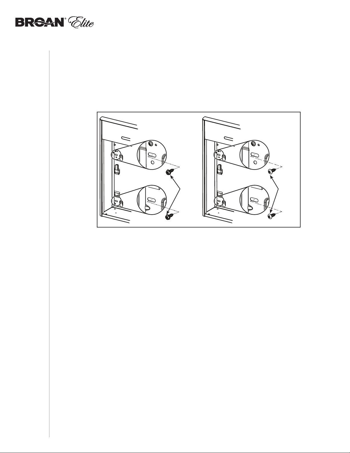
7 ] En los armarios con armazón, sujete la campana a los soportes EZ1 por medio de los
(4) tornillos para metal no 8-18 x 1/2” (los tornillos vienen en la bolsa de piezas). Introduzca
(2) tornillos en cada lado, en las ranuras (como se ve en los detalles de la ilustración de
abajo).
8 ] En los armarios sin armazón, sujete la campana al armario por medio de los (4) tornillos
de cabeza redonda para madera no 8 x 5/8” (los tornillos vienen en la bolsa de piezas).
Introduzca (2) tornillos en cada lado, en las ranuras (como se ve en los detalles de la
ilustración de abajo).
ARMARIO
CON ARMAZÓN
TORNILLOS
PA RA
METAL
ARMARIO
SIN ARMAZÓN
TORNILLOS
PA RA
MADERA
MANUAL DE INSTALACIÓN
1616
INSTALACÍON

Instalación normal (sin soportes EZ1)
3⅞"
13/16"
3/16"
5¼"
5¼"
7³/16"
12⅞" (
CAMPANA DE 30")
15⅞" (
CAMPANA DE 36")
12⅞" (
CAMPANA DE 30")
15⅞" (
CAMPANA DE 36")
LÍNEA
CENTRAL
ORIFICIO PARA
ALIMENTACIÓN ELÉCTRICA
(
EN LA PARED)
TORNILLOS DE
MONTAJE DE LA
CAMPANA (4)
ORIFICIO DE ACCESO PARA
CONDUCTO HORIZONTAL
PARTE
INFERIOR
DEL ARMARIO
CALZOS DE MADERA
(
ARMARIO CON PAR TE INFERIOR
REBAJADA
ÚNICAMENTE)
PARTE DELANTERA DEL ARMARIO
"
EVACIACIóN
VERTICAL
DE 7"
REDONDA
1 ] Use el diagrama adecuado de abajo para colocar los conductos y la alimentación eléctrica
en el armario o en la pared. Para una instalación sin conductos, NO corte el orificio de
acceso al conducto; corte sólo el orificio para el cableado eléctrico.
TORNILLOS DE MONTAJE
DE LA CAMPANA (4)
12⅞" (CAMPANA DE 30")
15⅞" (
CAMPANA DE 36")
PARTE DELANTERA DEL ARMARIO
5¼"
ORIFICIO DE ACCESO PARA
CONDUCTO VERTICAL
47/16"
EVACUACIÓN VERTICAL
DE 3¼” X 10”
CAMPANA DE 30")
12⅞" (
15⅞" (
CAMPANA DE 36")
PARTE INFERIOR
DEL ARMARIO
7³/16"
5¼"
1⅜"
3/4"
1015/16"
1½"
CALZOS DE MADERA
(
ARMARIO CON PAR TE INFERIOR
REBAJADA
ÚNICAMENTE)
TORNILLOS DE MONTAJE
DE LA CAMPANA (4)
12⅞" (
CAMPANA DE 30")
15⅞" (
CAMPANA DE 36")
PARTE DELANTERA DEL ARMARIO
ORIFICIO DE 8"
DE DIÁMETRO
4¹¹/16"
CALZOS DE MADERA
ARMARIO CON PAR TE INFERIOR
(
REBAJADA
ÚNICAMENTE)
LÍNEA
CENTRAL
12⅞" (
15⅞" (
EVACIACIóN
EVACUACIÓN
VERTICAL
VERTICAL
DE 7
DE 7"
REDONDA
REDONDA
LÍNEA
CENTRAL
ORIFICIO PARA
ALIMENTACIÓN ELÉCTRICA
EN LA PART E INFERIOR DEL ARMARIO)
(
EVACUACIÓN HORIZONTAL
DE 3¼” X 10”
EVACUACIÓN VERTICAL
DE 7” REDONDA
CAMPANA DE 30")
CAMPANA DE 36")
PARTE INFERIOR
DEL ARMARIO
16"
7³/
1⅜"
1½"
ORIFICIO PARA
ALIMENTACIÓN ELÉCTRICA
EN LA PART E INFERIOR DEL ARMARIO)
(
INSTALACÍON
MANUAL DE INSTALACIÓN
1015/16
2 ] Instale parcialmente cuatro (4) tornillos de montaje de CABEZA REDONDA no 8 x 5/8” en
el calzo o en el armario, de acuerdo con el diagrama adecuado de arriba. (Los tornillos de
montaje vienen en la bolsa de piezas, pero los calzos de madera y los tornillos de montaje
de los calzos no están incluidos).)
1717

Instale la campana (Instalación normal)
OTA: N Debido al peso de esta campana, se aconseja que la instalen dos instaladores.
1 ] Lleve el cable de alimentación de la vivienda del tablero de servicio al lugar de la campana.
Lleve el cable de alimentación de la vivienda a la campana a través de la descarga de
presión instalada previamente en la etapa 6 en la página 10.
2 ] Cuelgue la campana de los cuatro (4) tornillos de montaje instalados previamente. Coloque
de nuevo la campana contra la pared hasta que las cabezas de los tornillos de montaje se
introduzcan en el extremo estrecho de las ranuras de los orificios en forma de cerradura
en la parte superior de la campana. Mientras sujeta la campana, apriete los tornillos
firmemente. Sujete el cable de alimentación a la campana usando la descarga de presión.
INSTALACIÓN CON CONDUCTOS ÚNICAMENTE
3 ] Conecte los conductos a la campana y use cinta adhesiva metálica para sellar las juntas.
Asegúrese de que el conjunto de la clapeta (o la placa del conducto redondo) entra en el
conducto y que la clapeta se abre y se cierra sin dificultad.
MANUAL DE INSTALACIÓN
1818
INSTALACÍON

Conecte el cableado
!
ADVERTENCIA
Riesgo de descarga eléctrica. El cableado eléctrico debe hacerlo
personal cualifi cado de acuerdo con los códigos y normas aplicables.
Antes de conectar los hilos, corte la corriente en el tablero de servicio
y bloquee éste para evitar que se ponga en marcha accidentalmente.
HILO DE
TIERRA DEL
MOTOR
TORNILLO
DE TIERRA
CABLE DE
ALIMENTACIÓN
DE LA VIVIENDA
1 ] Conecte el cable de alimentación de la vivienda al cableado de la campana: El hilo NEGRO
con el NEGRO, el BLANCO con el BLANCO y el VERDE o el hilo pelado con el tornillo
VERDE de tierra.
PESTAÑAS DE LA
PARTE SUPERIOR
INTERNA DE
TORNILLO
2 ] Vuelva a instalar la tapa de cableados y sujétela a la campana con su tornillo de retención.
!
PRECAUCIÓN
Compruebe que ambas pestañas de la parte superior interna de la campana se hayan
introducido en sus ranuras correspondientes en la tapa de cableados. Asimismo,
procure que los hilos no queden pellizcados al volver a colocar la tapa.
LA CAMPANA
INTRODUCIDAS
EN LAS RANURAS
DE LA TAPA DE
CABLEADOS.
INSTALACÍON
MANUAL DE INSTALACIÓN
1919

Bombillas (Serie ALT1 solamente)
Las campanas ALT1 deben utilizar dos bombillas halógenas con pantalla de 120 V, 50 W máx.,
MR16 o PAR16 con base GU10 (incluidas).
NOTA: Antes de utilizar las lámparas, quite la cinta adhesiva que pueda haber sobre ellas.
!
ADVERTENCIA
No toque las bombillas mientras funcionen o poco después de que hayan dejado de
funcionar. Podría quemarse. Para prevenir riesgos de daños personales, instale sólo
bombillas halógenas con pantalla. Asimismo, no instale nunca una bombilla de haz frío,
dicróica o no adecuada para luces encastradas o pensada sólo para lámparas cerradas.
PLOMOS DE LA
BOMBILLA
1 ] Alinee los plomos de las bombillas con los pequeñas marcas situadas en el borde de la
ubicación de la lámpara en la campana (véase el detalle arriba) e instale las bombillas
colocando los plomos en sus acanaladuras en el casquillo.
2 ] Empuje suavemente hacia arriba y gire en el sentido de las agujas de un reloj hasta fijar la
bombilla.
NOTA: Puede usarse la ventosa que viene con la campana para instalar y retirar las bombillas.
Presione la ventosa contra la bombilla y gire en sentido contrario a las agujas de un reloj
para retirar la bombilla o en el sentido de las agujas de un reloj para instalar la bombilla.
!
La mayoría de las bombillas GU10 LED que suelen encontrarse en el mercado no
están pensadas para una cocina y puede que no funcionen como se anuncian. No se
aconseja usarlas con este producto.
ACANALADURAS
PARA LOS PLOMOS
DE LA BOMBILLA
(EN EL CASQUILLO)
MARCA
PRECAUCIÓN
VENTOSA
MANUAL DE INSTALACIÓN
2020
Instale los filtros
Instalación con conductos únicamente:
Vuelva a instalar los filtros de grasa que quitó en la etapa 2 , en la página 9 (sección “Prepare la
campana”).
Instalación sin conductos únicamente:
Compre dos filtros para instalación sin conductos a un distribuidor o minorista local (vea la
etiqueta de especificaciones del producto para el tipo de filtro). Instale los filtros sin conductos
siguiendo las instrucciones que vienen con los filtros.
INSTALACÍON

SERIE ALT1
12 34 56
1
2
3
4
J6
Interruptor
de anulación
J4
J10
Interfaz
1
2
3
4
5
6
7
8
Interfaz de usuario
conectado en J10
en la parte trasera
de la placa electrónica
J1
Transformador
J2
Potencia, Motor
5
4
3
2
1
5
4
3
2
1
6
7
Placa electrónica
R
R
AZ
AZ
NE
B
NE
NE
B
V/AM
R (Baja)
NA (Media)
NE (Alta)
B
120 V CA
V/AM
B
NE
NA
R
C
C/B
CÓDIGO DE COLORES
AZ
B
C
C/B
AZUL
BLANCO
CAFÉ
CAFÉ/BLANCO
NA
NE
R
V/AM
NARANJA
NEGRO
ROJO
VERDE/AMARILLO
MOTOR DEL
VENTILADOR
Línea
Neutro
Tierra
LED
1
2
3
4
5
6
R
NE
LED
LED
B
NE
Línea
Neutro
Tierra
120 V CA
SERIE ALT2
NE
Interruptor
de lampara
Interruptor
del motor
AM
AMARILLO
AZ
AZUL
B
BLANCO
1
2
1
2
V/AM
CÓDIGO DE COLORES
C
CAFÉ
C/B
CAFÉ/BLANCO
NA
NARANJA
AM (Baja)
AZ (Alta)
R (Baja)
NE (Alta)
B
B
NE
R
V/AM
B
NEGRO
ROJO
VERDE/AMARILLO
B
NE
NE
MOTOR DEL
VENTILADOR
6
5
4
NE
3
2
V/AM
1
R
NA
B
C
C/B
DIAGRAMAS DE CABLEADOS
MANUAL DE INSTALACIÓN
2121

SERIE ALT2
C
B
K
MANUAL DE INSTALACIÓN
2222
D
E
F
G
N. N. DE PIEZA DESCRIPCIÓN
P
S97020029
S97020030
1
S97020031
S98011873
2 SR680508 P
3 S97020534 CONJ. DE CLAPETA DE 3¼” X 10” (INCL. TORN.)11111111
4 S97020409
5 S97020407 H
6 SR99420635 C
S99010431-002
7
S99010431-003
8 S97020444 M
9 S97020445 T
S97020431
10
S97020432 C
S97020433 C
* S97020452 HARNÉS DE HILOS 11111111
* S98011637 T
* S97020360
S97020466
*
S97020467
* S99527587
* S97020470 E
* ÍTEM NO MOSTRADO.
PIEZAS DE REPUESTO
REPUESTOS Y REPARACIONES
Para que el aparato esté en buenas condiciones, use sólo repuestos genuinos Broan-NuTone LLC o Venmar Ventilation ULC. Los
repuestos genuinos Broan-NuTone LLC o Venmar Ventilation ULC están diseñados especialmente para cada unidad y han sido
fabricados para responder a las normas de certificación aplicables y mantener un alto nivel de seguridad. Los repuestos de otros
fabricantes pueden dañar seriamente el aparato y reducir drásticamente su nivel de rendimiento, lo cual podría causar una falla
prematura. Broan-NuTone LLC y Venmar Ventilation ULC recomiendan comunicar con un centro de servicios autorizado para todos los
repuestos y reparaciones.
LACA DE CUBIERTA DE RECIRCULACIÓN,
NEGRA (INCLUYE TORNILLOS)
LACA DE CUBIERTA DE RECIRCULACIÓN,
P
BLANCA (INCLUYE TORNILLOS)
LACA DE CUBIERTA DE RECIRCULACIÓN,
P
ACERO INOX. (INCLUYE TORNILLOS)
LACA DE CUBIERTA DE RECIRCULACIÓN,
P
ACERO INOX. NEGRO (INCLUYE TORNILLOS)
LACA DE CONDUCTO REDONDO DE 7” (INCL. TORN.)11111111
OTOR DEL VENTILADOR IMPELENTE
M
(INCL. 4 TORNILLOS Y 1 CONDENSADOR)
ÉLICE (INCLUYE N.° 6) 1 1 1 1 1 1 1 1
LIP DE LA HÉLICE 11111111
ILTRO DE GRASA - MICROFILTRACIÓN -
F
PATR óN OVALADO - C3 (JUEGO DE 2)
FILTRO DE GRASA - MICROFILTRACIÓN -
PATR óN OVALADO - D3 (JUEGO DE 2)
ÓDULO DE LED (JUEGO DE 2) 11111111
RANSFORMADOR 24 V 18 VA (INCL. TORN.)11 111111
ONT TÁCTILES SUAVES LED,
C
ACERO INOX. (INCL.TORNILLOS)
ONT. TÁCTILES SUAVES LED, BLANCO (INCL. TORN.) 1 1
ONT. TÁCTILES SUAVES LED, NEGRO (INCL. TORN.)11 11
APA DE CABLEADOS 11111111
BOLSA DE PIEZAS, INCLUYE: 4 TORNILLOS PARA
N.° 8-18 X 1/2”, 6 TORNILLOS DE
METAL
CABEZA REDONDA PARA MADERA N.° 8 X 5/8”,
6 TORNILLOS EMBUDITOS PARA MADERA
N.° 8 X 1/2”
ILTRO DE RECIRCULACIÓN - TIPO X C ( JUEGO
F
2) (INSTAL. SIN CONDUCTOS úNICAMENTE)
DE
ILTRO DE RECIRCULACIÓN - TIPO X D ( JUEGO
F
DE 2) (INSTAL. SIN CONDUCTOS úNICAMENTE)
UEGO DE SUJETADORES PARA FILTROS DE
J
CARBÓN – INCLUYE 4 SUJETADORES
QUIPO PARA FÁCIL INSTALACIÓN (INCL. TORN.) 1 1 1 1 1 1 1
I
J
H
30"
A
CERO
INOX. NEGRO
11
11111111
1111
11111111
11111111
11111111
N
30"
EGRA
30"
A
CERO
INOX.
11
CANTIDAD
36"
30"
N
LANCA
B
11
11
EGRA
11
36"
A
CERO
INOX. NEGRO
1111
1111
A
INOX.
36"
CERO
B
36"
LANCA

SERIE ALT1
D
C
B
J
E
I
F
G
H
N. N. DE PIEZA DESCRIPCIÓN
S97020029 P
S97020030 P
1
S97020031 P
2 SR680508 P
3 S97020534 C
4 S97020408 M
5 S97020407 H
6 SR99420635 C
S99010434-002 F
7
S99010434-003 F
S99030367 I
S99030355 I
8
S99030356 I
9 SV05921 B
* S97020448 H
* S98011637 T
* S97020292
S97020466
*
S97020467
* S99527587
* S97020470 E
* ÍTEM NO MOSTRADO.
LACA DE CUBIERTA DE RECIRCULACIÓN, NEGRA (INCL. TORNILLOS)1 1
LACA DE CUBIERTA DE RECIRCULACIÓN, BLANCA (INCL. TORNILLOS)1 1
LACA DE CUBIERTA DE RECIRC., ACERO INOX. (INCL. TORNILLOS)1 1
LACA DE CONDUCTO REDONDO DE 7” (INCL. TORNILLOS) 111111
ONJUNTO DE CLAPETA DE 3¼” X 10” (INCL. TORNILLOS) 111111
OTOR DEL VENTILADOR IMPELENTE (INCL. 4 TORNILLOS Y 1 CONDENSADOR)111111
ÉLICE (INCLUYE N° 6) 111111
LIP DE LA HÉLICE 111111
ILTRO DE GRASA - MICROFILTRACIÓN - TIPO C2 (JUEGO DE 2) 1 1 1
ILTRO DE GRASA - MICROFILTRACIÓN - TIPO D2 (JUEGO DE 2) 1 1 1
NTERRUPTOR OSCILANTE, GRIS (JUEGO DE 2) 1 1
NTERRUPTOR OSCILANTE, BLANCO (JUEGO DE 2) 1 1
NTERRUPTOR OSCILANTE, NEGRO (JUEGO DE 2) 1 1
OMBILLA HALÓGENA CON PANTALLA 50 W, GU10 2 2 2 2 2 2
ARNÉS DE HILOS 111111
APA DE CABLEADOS 111111
B
OLSA DE PIEZAS, INCLUYE: 4 TORNILLOS PARA METAL N.° 8-18 X 1/2”,
ORNILLOS DE CABEZA REDONDA PARA MADERA N.° 8 X 5/8”,
6 T
6 T
ORNILLOS EMBUDITOS PARA MADERA N.° 8 X 1/2”, 1 VENTOSA
ILTRO DE RECIRCULACIÓN - TIPO XC (JUEGO DE 2) (INSTALACIÓN
F
SIN CONDUCTOS úNICAMENTE)
ILTRO DE RECIRCULACIÓN - TIPO XD (JUEGO DE 2) (INSTALACIÓN
F
SIN CONDUCTOS úNICAMENTE)
UEGO DE SUJETADORES PARA FILTROS DE CARBÓN –
J
NCLUYE 4 SUJETADORES
I
QUIPO PARA FÁCIL INSTALACIÓN (INCLUYE TORNILLOS) 111111
B
30"
LANCA
CANTIDAD
36"
A
N
EGRA
11 1
36"
CERO
INOX.
B
36"
LANCA
30"
30"
A
N
CERO
EGRA
INOX.
111111
11 1
111111
PIEZAS DE REPUESTO
MANUAL DE INSTALACIÓN
REPUESTOS Y REPARACIONES
Para que el aparato esté en buenas condiciones, use sólo repuestos genuinos Broan-NuTone LLC. Los repuestos genuinos BroanNuTone LLC están diseñados especialmente para cada unidad y han sido fabricados para responder a las normas de certificación
aplicables y mantener un alto nivel de seguridad. Los repuestos de otros fabricantes pueden dañar seriamente el aparato y reducir
drásticamente su nivel de rendimiento, lo cual podría causar una falla prematura. Broan-NuTone LLC recomienda comunicar con un
centro de servicios autorizado para todos los repuestos y reparaciones.
2323

MANUAL DE INSTALACIÓN
2424
Periodo y exclusiones de la garantía: Broan-NuTone LLC o Venmar Ventilation ULC (sea esta la “Compañía”) garantiza al
consumidor comprador original de su producto (“usted”) que el producto (el “Producto”) estará libre de defectos en materiales o
en mano de obra, por un periodo de un (1) año a partir de la fecha de compra original (o por un periodo mayor según sea requerido
por la legislación aplicable). Para las campanas equipadas con módulos LED, la Compañía garantiza que los módulos LED y el
controlador de los módulos LED estarán libres de defectos materiales por un periodo de tres (3) años a partir de la fecha de compra original.
El periodo de garantía limitada para cualquier pieza de repuesto proporcionada por la compañía y para cualquier Producto
reparado o reemplazado bajo esta garantía limitada debe ser lo que reste del periodo de garantía original (o por un periodo mayor
según sea requerido por la legislación aplicable).
Esta garantía no cubre arrancadores de lámparas uorescentes, tubos, bombillas de halógeno e incandescentes, fusibles, ltros,
conductos, tapas de techo, tapas de pared ni otros accesorios que pudieran ser comprados por separado e instalados con el
producto. Esta garantía tampoco cubre (a) mantenimiento y servicio normal, (b) uso y desgaste normal, (c) Productos o piezas
sujetos a mal uso, abuso, uso anormal, negligencia, accidente, mantenimiento inadecuado o insu ciente, almacenamiento o
reparación (que no sea reparación por parte de la Compañía), (d) daños causados por instalación defectuosa, o bien instalación
o uso contrario a las recomendaciones o instrucciones, (e) cualquier Producto que se haya movido de su punto de instalación
original, (f) daños ocasionados por el medio ambiente o los elementos naturales, (g) daños en tránsito, (h) desgaste natural del
acabado, (i) Productos en uso comercial o no residencial, o (j) daños ocasionados por incendio, inundación u otro caso fortuito o
(k) Productos con un número de serie alterado, removido o mutilado. Esta garantía cubre solamente Productos vendidos a clientes
originales en los Estados Unidos y Canadá por la Compañía o a distribuidores de EE. UU. y Canadá autorizados por la Compañía.
Esta garantía sustituye todas las garantías anteriores y no es transferible del comprador consumidor original.
No hay otras garantías: Esta garantía limitada contiene la única obligación de la Compañía y su único recurso ante productos
defectuosos. Las garantías anteriores son exclusivas y en lugar de cualquier otra garantía, expresa o implícita. LA COMPAÑÍA
NIEGA Y EXCLUYE CUALQUIER OTRA GARANTÍA EXPRESA, Y NIEGA Y EXCLUYE TODAS LAS GARANTÍAS IMPLÍCITAS,
CONDICIONES Y ESTIPULACIONES IMPLICITAS POR LEY, INCLUYENDO, ENTRE OTRAS, LAS DE COMERCIALIZACIÓN
Y APTITUD PARA UN PROPÓSITO EN PARTICULAR. Hasta el grado en que la ley aplicable prohíba la exclusión de las
garantías implícitas, condiciones y estipulaciones, la duración de cualquier garantía implícita aplicable está limitada al periodo
especi cado para la garantía expresa antes mencionada. Algunas jurisdicciones no permiten limitaciones en la duración de una
garantía implícita, así que la limitación anterior tal vez no aplique en su caso. Cualquier descripción verbal o escrita del Producto
es para el único propósito de identi carlo y no deberá considerarse como una garantía expresa.
Siempre que sea posible, toda disposición de esta garantía limitada deberá ser interpretada de tal forma que sea efectiva y válida de
conformidad con la ley aplicable, pero si alguna disposición fuera considerada prohibida o inválida, quedará sin efecto solo en virtud
de dicha prohibición o invalidez, sin invalidar el resto de dicha disposición o las demás disposiciones restantes de la garantía limitada.
Recurso: Durante el periodo de garantía limitada aplicable, la Compañía, a su opción, suministrará piezas de repuesto, o reparará
o reemplazará, sin cargo alguno, cualquier Producto o pieza del mismo, hasta el grado en que la Compañía lo encuentre cubierto
bajo esta garantía limitada y en incumplimiento de la misma en condiciones normales de uso y servicio. La Compañía le enviará
el Producto reparado o reemplazado o las piezas de repuesto sin cargo. Usted es responsable de todos los costos de retiro,
reinstalación y envío, seguro u otros cargos de ete incurridos en el envío del Producto o pieza a la Compañía. Si debe enviar el
Producto o la pieza a la Compañía, tal como lo indique la Compañía, debe empaquetar adecuadamente el Producto o la pieza: la
Compañía no se hace responsable por los daños en tránsito. La Compañía se reserva el derecho de utilizar Productos o piezas
reacondicionados, renovados, reparados o refabricados en el proceso de reemplazo o reparación de garantía. Dichos Productos
y piezas serán comparables en función y desempeño a un Producto o una pieza original y tendrán garantía durante el resto del
periodo de la garantía original (o po un periodo mayor según sea requerido por la legislación aplicable).
La Compañía se reserva el derecho, a su sola discreción, a devolver el dinero que pagó por el Producto en lugar de la reparación o
sustitución. Si el producto o componente ya no está disponible o esta descontinuado, el reemplazo podrá ser efectuado por un producto
similar de igual o mayor valor, a criterio exclusivo de la Compañía. Este es su único y exclusivo recurso por incumplimiento de esta garantía limitada.
Exclusión de daños: LA OBLIGACIÓN DE LA COMPAÑÍA DE SUMINISTRAR PIEZAS DE REPUESTO, O DE REPARAR
O REEMPLAZAR, A OPCIÓN DE LA COMPAÑÍA, SERÁ SU ÚNICO Y EXCLUSIVO RECURSO BAJO ESTA GARANTÍA
LIMITADA, Y LA ÚNICA Y EXCLUSIVA OBLIGACIÓN DE LA COMPAÑÍA. LA COMPAÑÍA NO SERÁ RESPONSABLE POR
DAÑOS INCIDENTALES, INDIRECTOS, RESULTANTES O ESPECIALES QUE SURJAN POR EL USO O DESEMPEÑO DEL
PRODUCTO, O EN RELACIÓN CON EL MISMO. Los daños incidentales incluyen pero no se limitan a daños tales como pérdida
de uso. Los daños consecuentes incluyen pero no se limitan a los gastos de reparación o sustitución de otra propiedad que fue
dañada si el Producto no funcionase apropiadamente.
LA COMPAÑIA NE SERÁ RESPONSABLE ANTE USTED, NI NINGÚN DERECHOHABIENTE, DE CUALQUIER OTRA OBLIGACIÓN
O RESPONSABILIDAD INCLUYENDO, PERO NO LIMITADO A, OBLIGACIONES O RESPONSABILIDADES DERIVADAS DEL
INCUMPLIMIENTO DE CONTRATO O GARANTÍA, NEGLIGENCIA U OTRO AGRAVIO O CULAQUIER TEORÍA DE RESPONSABILIDAD
OBJETIVA, CON RESPECTO AL PRODUCTO O ACTOS U OMISIONES DE LA COMPAÑIA DE CUALQUIER OTRA FORMA.
Algunas jurisdicciones no permiten la exclusión o limitación de daños incidentales o resultantes, por lo que la limitación antes
mencionada podría no aplicarse a usted. Esta garantía le otorga derechos legales especí cos, y usted podría tener otros derechos
que varían de jurisdicción a jurisdicción. Las aclaraciones, exclusiones y limitaciones de responsabilidad bajo esta garantía no
aplicarán en la medida que lo prohiban las leyes aplicables.
Esta garantía cubre únicamente el reemplazo o la reparación de Productos defectuosos o piezas de los mismos en la planta
principal de la Compañía, y no incluye el costo del viaje para el servicio de campo ni los viáticos.
Cualquier asistencia que proporcione o procure la Compañía para usted fuera de los términos, limitaciones o exclusiones de esta garantía
limitada no constituirá una renuncia a dichos términos, limitaciones o exclusiones, ni dicha asistencia extenderá o renovará la
La Compañía no le reembolsará ningún gasto en el que usted haya incurrido al reparar o reemplazar cualquier Producto
defectuoso, excepto los incurridos con el permiso previo por escrito de la Compañía.
Cómo obtener el servicio cubierto por la garantía: Para tener derecho al servicio cubierto por la garantía, usted debe (a)
GARANTÍA
noti car a la Compañía a la dirección o número de teléfono que aparecen abajo en un plazo de siete (7) días después de descubrir
el defecto cubierto, (b) proporcionar el número de modelo y la identi cación de la pieza y (c) describir la naturaleza de cualquier
defecto en el Producto o la pieza. En el momento de solicitar el servicio cubierto por la garantía, debe presentar un comprobante
de la fecha de compra original. Si usted no puede presentar una copia de la garantía limitada original por escrito, entonces regirán
los términos de la garantía limitada por escrito más actualizada de la compañía para su producto en particular. Las garantías
limitadas por escrito más actualizadas para los productos de la Compañía se pueden encontrar en www.broan.com y www.broan.ca
Broan-NuTone LLC 926 West State Street, Hartford, WI 53027 www.broan.com 800-637-1453
Venmar Ventilation ULC, 550 Lemire Blvd., Drummondville, Québec, Canada J2C 7W9 www.broan.ca 1-877-896-1119
Garantía limitada
garantía.
 Loading...