

Page 1
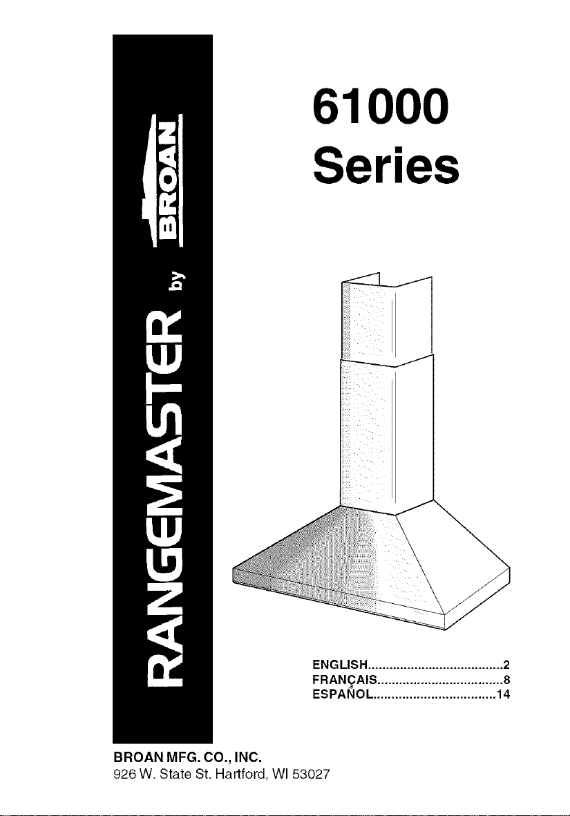
61000
Series
ENGLISH ...................................... 2
FRAN_AIS ................................... 8
ESPANOL .................................. 14
BROAN MFG. CO., INC.
926 W. State St. Hartford, WI 53027
Page 2
WARNING WARNING
SUITABLE FOR USE IN HOUSEHOLD
COOKING AREA.
TO REDUCETHE RISK OF FIRE, ELECTRICAL
SHOCK, OR INJURY TO PERSONS, OBSERVE
THE FOLLOWING:
1. Use this unit only in the manner intended by
the manufacturer. Ifyou have questions, con-
tact the manufacturer at the address or tele-
phone number listed in the warranty.
2. Before servicing or cleaning unit, switch power
off at service panel and lock service panel to
prevent power from being switched on
accidentally. When the service disconnecting
means cannot be locked, securely fasten a
prominent warning device, such as a tag, to
the service panel.
3. Installation work and electrical wiring must be
done by a qualified person(s) in accordance
with all applicable codes and standards, includ-
ing fire-rated construction codes and stan-
dards.
4. Sufficient air is needed for proper combustion
and exhausting of gases through the flue (chim-
ney) of fuel burning equipment to prevent
backdrafting. Follow the heating equipment
manufacturer's guidelines and safety stan-
dards such as those published by the National
Fire Protection Association (NFPA), and the
American Society for Heating, Refrigeration
and Air Conditioning Engineers (ASHRAE), and
the local code authorities.
5. When cutting or drilling into wall or ceiling, do
not damage electrical wiring and other hidden
utilities.
6. Ducted fans must always be vented to the out-
doors.
7. Do not use this unit with any solid-state speed
control device.
8. To reduce the risk of fire, use only steel
ductwork.
9. This unit must be grounded.
TO REDUCE THE RISK OF A RANGE TOP
GREASE FIRE:
A. Neverleave surface units unattended athigh settings.
Boilovers cause smoking and greasy spillovers that
may ignite.Heat oils slowlyon lowormedium settings.
B. Always turn hood ON when cooking at highheat or
when cookingflaming foods.
C. Clean ventilating fans frequently. Grease should not
beallowed to accumulate on fanor filter.
D. Use properpansize.Always usecookwareappropriate
for thesize of the surface element.
TO REDUCE THE RISK OF INJURY TO PER-
SONS IN THE EVENT OF A RANGE TOP
GREASE FIRE, OBSERVETHE FOLLOWING:*
1. SMOTHER FLAMES with a close-fitting lid,
cookie sheet, or metal tray, then turn off the
burner. BE CAREFULTO PREVENT BURNS.
Ifthe flames do not go out immediately, EVACU-
ATEAND CALLTHE FIRE DEPARTMENT.
2. NEVER PICK UPAFLAMING PAN -You may
be burned.
3. DO NOT USE WATER, including wet dishcloths
or towels - violent steam explosion will result.
4. Use an extinguisher ONLY if:
A. You know you have a Class ABC extin-
guisher and you already know how to op-
erate it.
B. The fire is small and contained in the area
where it started.
C. The fire department is being called.
D. You can fight the fire with your back to an
exit.
* Based on "Kitchen Fire Safety iqps" pub-
lished by NFPA.
CAUTION
1. To reduce risk of fire and to properly exhaust air,
be sure to duct air outside. Do not vent exhaust
air into spaces within walls or ceilings or into
attics, crawl spaces, or garages.
2. Take care when using cleaning agents or
detergents.
3. Avoid using food products that produce flames
under the Range Hood.
4. For general ventilating use only. Do not use to
exhaust hazardous or explosive materials and
vapors.
5. To avoid motor bearing damage and noisy and/
or unbalanced impellers, keep drywall spray,
construction dust, etc. off power unit.
6. Your hood motor has a thermal overload which
will automatically shut off the motor if it becomes
overheated. The motor will restart when it cools
down. If the motor continues to shut off and
restart, have the hood serviced.
7. For best capture of cooking impurities, the
bottom of the hood should be a minimum of 24"
and a maximum of 30" above the cooking sur-
face.
8. Two installers are recommended because of the
large size and weight of this hood.
9. Please read specification label on product for
further information and requirements.
-2-
Page 3

INSTALL BACKSPLASH (OPTIONAL)I ROOFCAP
I
\
If optional backsplash is used, attach it to the
finished wall. Secure hood mounting brackets
to the backsplash and omit wall framing
described below.
INSTALL THE DUCTWORK
NOTE: To reduce the risk of fire, use only
metal ductwork.
1. Decide where the ductwork will run between
the hood and the outside.
2. A straight, short duct run will allow the hood
to perform most efficiently.
3. Long duct runs, elbows, and transitions will
reduce the performance of the hood. Use as
few of them as possible.
FRAMING BEHIND DRYWALL
4. Install a roof or wall cap. Connect 6" round
metal ductwork to cap and work back to-
wards hood location. Use duct tape to seal
the joints between ductwork sections.
INSTALL MOUNTING
BRACKETS
1. Construct wood wall framing that is flush
with interior surface of wall studs.
Make sure:
a) the framing is centered over installation
location.
b) the height of the framing will allow the
mounting brackets to be secured to the
framing within the dimensions shown.
2. After wall surface is finished secure mount-
ing brackets to framing using dimensions
shown.
30s#,''= bottom of hood 24" above cooktop
36%"= bottom of hood 30" above cooktop
RECTANGULAR CUTOUTS
6"ROUND
DUCT
WALL
CAP
ROUNC
ELBOW
C_'Oktop
MOUNTING
BRACKETS
INSTALL THE HOOD
3. Hang the hood from the brackets through
the rectangular cut-outs on the back of the
hood. Cut-outs are larger than the brackets
to allow for horizontal adjustment.
The bottom of the hood should be 24" to 30"
above the cooking surface.
4. Height adjustment screws provide vertical
adjustment.
5. Depth adjustment screws provide horizon-
tal adjustment.
6. Secure the hood with additional mounting
screws. Use drywall anchors, provided, if
wall studs or framing are not available.
-3-
ADDITIONAL
MOUNTING
SCREWS
SCREWS
HEIGHT
ADJUSTMENT
SCREWS
ADDITIONAL
MOUNTING "_-
SCREWS
WALL FRAMING
Page 4
WIRING
Note: This range hood must be properly
grounded. The unit should be installed by a
qualified electrician in accordance with all
applicable national and local electrical codes.
1. Remove the wiring box cover. Remove a
knockout from the wiring box.
2. Feed 6" of power cable through the knock-
out opening and secure cable to the wiring
box with an appropriate connector.
3. Make electrical connections. Connect white
to white, black to black and green to green.
4. Replace wiring box cover and screws. Make
sure that wires are not pinched between
cover and box.
CONNECT DUCTWORK
Ducted Configuration
1. Use screws and wall anchors to secure up-
per bracket to the ceiling and wall as shown.
2. Use 6" round metal duct to connect the duct
collar on the hood to the ductwork above.
3. Use duct tape to make all joints secure and
air tight.
4. Connect the upper section of decorative flue
to the bracket with screws provided.
5. Slide the lower section of decorative flue
downward, until it fits properly around hood.
6. Secure decorative flue to hood with screws
provided.
WIRING BOX
DUCT COVER
COLLAR
FASTEN e,'-- +- "_
FLUE TO
HOOD &
UPPER
BRACKET
WITH
SCREWS
,1 DECORATIVE
FLUE
DUCT TAPE
I_+1_ AIR VENT
_--H POSITION FOR
" II
-4-
Page 5
CONNECT DUCTWORK
Ductfree Configuration
1. Use screws and wall anchors (sup-
plied) to secure the upper bracket
to wall and ceiling as shown.
2. Turn upper flue section upside down
so air vents are at the top. Slide up-
per flue section into lower flue sec-
tion.
3. Snap theplastic duct collar intothe
hole in the bottom of theducfree ple-
num. Connect the ductfree plenum
to the upper flue section with (4) flat-
head screws (supplied).
4. Measure the distance from the top
of the discharge collar to the ceil-
ing. Cut a length of 6" round metal
duct 6" shorter than this dimension.
5. Fit duct section over the plastic duct
collar. For best fit, make sure duct
seam is toward the front.
6. Set duct/flue assembly on hood with top tilted away from wall. Reach around flue
to engage bottom of duct with discharge collar on hood. Tilt flue up against wall.
Upper flue section can be cut to length if necessary.
7. Raise upper flue section and screw it to upper bracket with (2) screws (supplied).
Screw lower flue section to hood with screws (supplied).
UPPER
FLUE SECTION UPPER
_( AIR BRACKET
In uppVEIIN,TeSsection)/
DUCTFRE W
PLENUM _-_'_-'_,_ IIll
PLAST,C
DUCTCOLLAR\ AS,RE
LO_ER_I_\_ _I\
FLUE SECTI
6" ROUND
.ETALDUCT
D,SCHAROE7------=
COLLAR
/
DUCTFREE FILTER
INSTALLATION
1. Purchase a ductfree filter kit (ROUND
FILTER) from your dealer.
2. Position the filters over the mounting
brackets on the blower inlet.
Rotate to lock filters in place.
-5-
Page 6
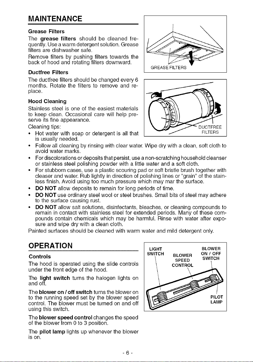
MAINTENANCE
Grease Filters
The grease filters should be cleaned fre-
quently. Use awarm detergent solution. Grease
filters are dishwasher safe.
Remove filters by pushing filters towards the
back of hood and rotating filters downward.
Ductfree Filters
The ductfree filters should be changed every 6
months. Rotate the filters to remove and re-
place.
Hood Cleaning
Stainless steel is one of the easiest materials
to keep clean. Occasional care will help pre-
serve its fine appearance.
Cleaning tips:
• Hot water with soap or detergent is all that FILTERS
is usually needed.
• Follow all cleaning by rinsing with clear water. Wipe dry with a clean, soft cloth to
avoid water marks.
• For discolorations or deposits that persist, use a non-scratching household cleanser
or stainless steel polishing powder with a little water and a soft cloth.
• For stubborn cases, use a plastic scouring pad or soft bristle brush together with
cleaser and water. Rub lightly in direction of polishing lines or "grain" of the stain-
less finish. Avoid using too much pressure which may mar the surface.
• DO NOT allow deposits to remain for long periods of time.
• DO NOT use ordinary steel wool or steel brushes. Small bits of steel may adhere
to the surface causing rust.
• DO NOT allow salt solutions, disinfectants, bleaches, or cleaning compounds to
remain in contact with stainless steel for extended periods. Many of these com-
pounds contain chemicals which may be harmful. Rinse with water after expo-
sure and wipe dry with a clean cloth.
Painted surfaces should be cleaned with warm water and mild detergent only.
GREASE FILTERS
OPERATION
Controls
The hood is operated using the slide controls
under the front edge of the hood.
The light switch turns the halogen lights on
and off.
The blower on /off switch turns the blower on
to the running speed set by the blower speed
control. The blower must be turned on and off
using this switch.
The blower speed control changes the speed
of the blower from 0 to 3 position.
The pilot lamp lights up whenever the blower
is on.
-6-
LIGHT
SWITCH
BLOWER ON / OFF
SPEED SWITCH
_,_\_,t_// PILOT
BLOWER
LAMP
Page 7
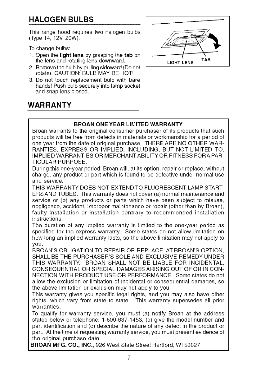
HALOGEN BULBS
This range hood requires two halogen bulbs
(Type T4, 12V, 20W).
To change bulbs:
1. Open the light lens by grasping the tab on
the lens and rotating lens downward.
2. Remove the bulb by pulling sideward (Do not
rotate). CAUTION: BULB MAY BE HOT!
3. Do not touch replacement bulb with bare
hands! Push bulb securely into lamp socket
and snap lens closed.
LIGHT LENS
TAB
WARRANTY
BROAN ONE YEAR LIMITED WARRANTY
Broan warrants to the original consumer purchaser of its products that such
products will be free from defects in materials or workmanship for a period of
one year from the date of original purchase. THERE ARE NO OTHER WAR-
RANTIES, EXPRESS OR IMPLIED, INCLUDING, BUT NOT LIMITED TO,
IMPLIED WARRANTIES OR MERCHANTABILITY OR FITNESS FORA PAR-
TICULAR PURPOSE.
During this one-year period, Broan will, at its option, repair or replace, without
charge, any product or part which is found to be defective under normal use
and service.
THIS WARRANTY DOES NOT EXTEND TO FLUORESCENT LAMP START-
ERSAND TUBES. This warranty does not cover (a) normal maintenance and
service or (b) any products or parts which have been subject to misuse,
negligence, accident, improper maintenance or repair (other than by Broan),
faulty installation or installation contrary to recommended installation
instructions.
The duration of any implied warranty is limited to the one-year period as
specified for the express warranty. Some states do not allow limitation on
how long an implied warranty lasts, so the above limitation may not apply to
you.
BROAN'S OBLIGATION TO REPAIR OR REPLACE, AT BROAN'S OPTION,
SHALL BE THE PURCHASER'S SOLEAND EXCLUSIVE REMEDY UNDER
THIS WARRANTY. BROAN SHALL NOT BE LIABLE FOR INCIDENTAL,
CONSEQUENTIAL OR SPECIAL DAMAGES ARISING OUT OF OR IN CON-
NECTION WITH PRODUCT USE OR PERFORMANCE. Some states do not
allow the exclusion or limitation of incidental or consequential damages, so
the above limitation or exclusion may not apply to you.
This warranty gives you specific legal rights, and you may also have other
rights, which vary from state to state. This warranty supersedes all prior
warranties.
To qualify for warranty service, you must (a) notify Broan at the address
stated below or telephone: 1-800-637-1453, (b) give the model number and
part identification and (c) describe the nature of any defect in the product or
part. At the time of requesting warranty service, you must present evidence of
the original purchase date.
BROAN MFG. CO., INC., 926 West State Street Hartford, WI 53027
-7-
Page 8
AVERTISSEMENTS
PEUTETRE UTILISEDANS LESZONES CUISSON DES
CUISINES FAMILIALES.
POUR REDUIRE LES RISQUES D'INCENDIE. DE
DECHARGES ELECTRIQUESOUDEDOMMA-GESAUX
PERSONNES, OBSERVEZ LES IN-STRUCTIONS
SUIVANTES:
1. N'utilieezcetappareilque commecela estindique parle
constructeur.Sivous avezdes problemes,contactezle
fabriquant a I'adresse ou au numero de telephone
indiquesdans lagarantie.
2. Avant depourvoiral'entretien ouau nettoyage devotre
appareil, eteignez-le au tableau des commandes ou
bloquez le tableau des commandes afind'eviter de le
mettreenmarche accidentellement. Sivous ne pouvez
pas bloquer le systeme permettant d'eteindre votre
appareil, appliquez un avertissement exterieur d'une
fagon sure, comme par exemple un panneau, sur le
tableau descommandes.
3. L'assemblageetlaconnexion_lectriquedoivent_trefaits
pardespersonnes qualifi_es enrespectant les normes
et reglements en vigueur, y compris les normes et
reglementsconcemant les possibilitesd'incendie.
4. IIestindispensablequ'ilyaitsuffisammentd'airpourque
lacombustion etI'evacuation desgaz atraversle tuyau
dubrQleurducombustibleaitlieusans retourdeflamme.
SuivezlesindicationsdonneesparlefabricantdubrQleur
ainsique lesnormes de s_curit_comme celles qui sent
publieespar I'Association Nationale pour laProtection
contrelesIncendies NationalFireProtectionAssociation
(NFPA)etlaAmerican SocietyforHeating,Refrigeration
andAirConditioningEngineers(ASHRAE),etlesautorites
localesen matieredenormes.
5. Quandvouecoupezou percez destrousdanele murou
le plafond, n'abfmez pas les fils electriquesou autres.
6. Leventilateur canaliee doittoujours evacuer I'airvers
rexterieur.
7. N'utilisezpascet appareil avecun appareil contr61antla
vitesse aetat solide.
8. Afindediminuertout risqued'incendie n'utilisezquedes
conduits en metal.
9. Votreappareildoit _tre reliealaterre.
ATTENTION - POUR REDUIRE LES RISQUES
D'INCENDIE DES MATIERESGRASSES QUISONT EN
TRAIN DE CUIRE:
A. Ne laissez jamais ni vos elements chauffants, ni vos
casseroles ou po_les sur lefeu sans les contr61ersi
vous reglezI'apportde chaleur sur une positionelevee.
Sivos casseroles ou po_les debordent celaprovoque
delavapeuret des_claboussuresde graissequipeuvent
prendrefeu.Chauffezleshuiles lentement afeu basou
moyen.
B. Faitestoujoursfonctionnervotrehottequandvouscuisez
des temperatures elevees ou quand vous cuieinez
des platsflambes.
C. Nettoyez regulierement les ailes de vos ventilateurs.
Ne permettez pas que la graisse s'accumule sur le
ventilateur ousur le filtre.
D. Utilieez des casseroles de taille appropriee. Utilisez
toujours des usteneiles de cuisson dent la taille est
appropriee a lasurface de votre element decuieson.
AVERTISSEMENTS
POUR REDUIRE LES RISQtJES DE DOMMAGES AUX
PERSONNES AU CAS OU VOTRE CUISI-NIERE
PRENDRAIT FEU, OBSERVEZ LES INSTRUCTIONS
SUIVANTES:*
1. ETEINDRE LESFLAMMES aI'aide d'un couvercle le
plushermetiquepossible, une plaqueb.g&teaux,ouun
plateauenmetal, puis eteindre le brQleur.ATTENTION
NEPASVOUSBRULER.Silesflammesne s'eteignent
pas immediatement, SORTEZ ET APPELEZ LES
POMPIERS.
2. NEPRENEZJAMAIS EN MAINUNE POI_LEOU UNE
CASSEROLE QUI A PRISFEU -Voue pourriez vous
brQler.
3. N'UTILISEZ PAS D'EAU, ni torchons ou serviettes
mouilles-vous provoqueriezuneviolenteexplosion de
vapeur.
4. Utilisezun extincteurSEULEMENT si:
A. Vous savez que vous avez un extincteur Classe
ABC, etvous enconnaissez deja lemoded'emploi.
B. Cen'est pasuntres gros incendie etqu'il se limite
I'endroioQil aexplose.
C. Vous_tes en traind'avertir lespompiers.
D. Voueavezlapossibilited'essayerd'eteindrerincendie
enayant le dostourne vers uneissue.
D'apresles"SuggestionsconcernantlaSecurit_centre
lesincendies des cuisines" publiees par NFPA.
ATTENTION
1. Pour reduire tout risque d'incendie et pour evacuer
correctementI'air, assurez-vous de prevoirunconduit
de ventilation exterieur. Ne videz pas I'air dans les
espaces limites par des murs ou des plafonds, les
combles, lespassages etroitsou les garages.
2. Faites tres attention quand vous utilisez des produits
denettoyage ou desdetergents.
3. Evitez d'utiliser des aliments pouvant s'enflammer sous
la Range Hood.
4. N'utilisezcetappareilquepouruneventilationgenerale.
Ne I'utilieez pas pour evacuer des matieres ou des
vapeurs dangereuses ou qui peuvent exploser.
5. Poureviter de causer desdommages aumoteur et de
rendre les rotors bruyantset/ou non equilibres, evitez
que les sprays pour murs secs, la poussiere de
constructionentrenten contactavec lapartieelectrique.
6. Lemoteur de votre hotte a unthermostat qui eteindra
automatiquementle moteurs'il estsurchauffe.Lemoteur
se remettra en marche Iorsqu'il se sera refroidi. Si le
moteurcontinueas'eteindreetase remettreenmarche,
faites verifier votre hotte.
7. Pourmieuxcapturer lesimpuretesde cuisine, le basde
votre hottedevrait_tre aune distance minimumde24"
eta une distance maximum de 30" au-dessus du plan
decuieson.
8,
Vu que cette hotte est grande et Iourde, il est
recommande de confier I'inetallation de cette hotte
deuxpersonnes.
9.
Nousvous recommandons delire I'etiquetteindiquant
lescaracteristiquesdevotre hottepourdeplus amples
informatione et exigences.
8-
Page 9

INSTALLATION DU PANNEAU
POSTERIEUR (OPTIONNEL)
Si vous avez choisid'utiliser le panneauposterieur,
accrochez-leaumur. Fixezlesetriersd'assemblage
au panneau mais n'assemblez pas le cadre allant
contre le tour qui est decrit plus bas.
INSTALLATION DU SYSTEME
D'EVACUATION
REMARQUE: Pour reduire les risques
d'incendie, n'utilisez que des tuyaux en metal.
1. Decidez o_Jle tuyau doit 6tre installe, entre
votre hotte et I'exterieur.
2. Un tuyau droit et court permettra & votre hotte
de fonctionner d'une fa_on plus efficace.
3. Un tuyau long avec des coudes et des
transitions reduira le bon fonctionnement de
votre hotte. En utiliser le moins possible.
4. Installez un couvercle sur le toit ou au mur.
Reliez un tuyau en metal fond de 8" au
couvercle et faites-le aller jusqu'& I'empla-
cement de votre hotte. Rendez les jonctions
du tuyau hermetiques au moyen d'un ruban
pour tuyaux.
INSTALLATION DES ETRIERS
D'ASSEMBLAGE
1. Construisez uncadreen bois pour lemur dont
les vis-pivot ne depassent pas. Assurez-vous:
a) que le cadre est centre au-dessus de
I'emplacement de I'installation.
b) la hauteur du cadre permettra que les
etriers d'assemblage soient fixes au cadre
en respectant les dimensions indiquees.
2. Apres avoir termine la surface du mur fixez les
etriers d'assemblage au cadre en respectant
les dimensions qui sont indiquees.
INSTALLATION DE VOTRE HOTTE
1. Accrochez votre hotte aux etriers par les
trous rectangulaires qui se trouvent
derriere votre hotte. Les trous sont plus
grands que les etriers afin de vous permettre
d'ajuster le tout horizontalement. Le fond de
votre hotte devrait 6tre a entre 24" et 30" au-
dessus de la surface de cuisson.
2. Les vie de reglage en hauteur permettent
de regler verticalement.
3. Les vis de reglage en profondeur
permettent de regler horizontalement.
4. Fixez votre hotte avec des vie d'assemblage
de securite. Utilisez des chevilles pour mur
sec, qui vous sont foumies, si vous ne trouvez
pas les vis-pivot ou le cadre.
- 9 -
COUVERCLE DU TOIT /
TOYAU NOND
DE 6"
CONDUIT
DECORATIF
HO'I-rE
_E 24"
DU PLAN DE CUISSON
CADRE POUR LEMUR
8 aU.¢l "
_n esst_ fill
30/_'- sitadistanceentrelahntteet _ep_andecuiss0nc'estde24"
36_f_"=sitadistanceentrelahntteetteplandecuiss0nc'estde30"
TROUS RECTANGULAIRES
ETRIERS
DE SECURITE
VIS DE REGLAGE
PROFONDEUR
VIS DE
REGLAGE EN
HAUTEUR
VIS D'ASSEMBLAGE
DE SECURITE
PLANCHE DE
POUR L'ADAPTATION
1
/
Page 10

INSTALLATION ELECTRIQUE
Remarque: Ce modele de hotte dolt _tre relie
a la terre correctement. Cet article devrait
_tre installe par un electricien qualifie selon
les lois nationales et locales en matiere
d'electricit&
1. Enlevez le couvercle de la boite de
connexion electrique. Ouvrez un trou de la
bofte de connexion electrique.
2. Faites passer un cable electrique de 6" dans
le trou et fixez le cable a la bofte de
connexion au moyen d'un connecteur
appropri&
3. Faites le raccordement electrique. Reliez le
blanc au blanc, le noir au noir et le vert au
vert.
4. Remettez le couvercle de la bofte de
connexion et les vis. Assurez-vous que les
fils se sont pas coinces entre le couvercle et
la bofte.
CONNEXION DU SYSTEME
D'EVACUATION
Modele avec tuyau d'evacuation
1. Attachez I'etrier du haut au plafond et au
mur au moyen des vis et des chevilles
comme cela est indiqu&
2. Reliez le collier du tuyau qui se trouve sur
votre hotte au systeme de conduction qui se
trouve au-dessus au moyen d'untuyau rond
en metal de 6".
3. Utilisez un ruban pour tuyauterie afin de
rendre toutes les jonctions sures et
etanches.
4. Reliez le haut de conduit decoratif a I'etrier
au moyen des vis qui vous sont foumies.
5. Faites glisser la section du bas du conduit
decoratif vers le bas, jusqu'&ce qu'il adhere
correctement autour de la hotte.
6. Fixez le conduit decoratif a votre hotte au
moyen des vis qui vous sont foumies.
ATTACHEZ LE e..-
TUYAU .&. VOTRE
HOTTE ETA
L'I_TRIER DU
HAUT AU
MOYEN DES VlS
COUVERCLE DE
LA BO|TE DE
COLLIER DU CONNEXION
TUYAU
ETRIER DU
HAUT "_J_ 0 ATTACHEZ
_"T_I_'_L' ETRIE R DU
_q HAUT AU
!$ PLAFOND ET
r AU MUR AU
MOYEN DES
VIS (et des
est
CONDUIT
/'q)C:CORATIF
RUBAN POUR
/TUYAUTERIE
/ POSITION
EVACUATION DE
L_AIR POUR
MODF:LE
EVACUANT
L'AIR
TUYAU ROND EN
METAL DE 6"
-10-
Page 11

CONNEXION DU SY-
STEME D'EVACUATION
SECTION DU
HAUT DU EVACUATION DE ETRIER DU
CONDUIT _ L'AIR (secUon du / HAUT
Modele recyclant rair
1. Attachez I'etrier du haut (qui vous
est fourni) au plafond et au mur au
moyen des vis et des chevilles
comme cela est indique.
2. Faites toumer la section d'en haut
du conduit vers le has de sorte que
la evacuation de I'air soitvers le haut.
Faites glisser la section du haut du
conduit dans la section du bas du
conduit.
3. Poussez le collier du tuyau en
plastique darts le trou qui se trouve
au fond du deflecteur. Reliez le
OEFLEOTEUR ? - \-....Ill/
COLL'ER Ill/
TUYAU EN _ /_ _ MESURE
FLAST.OUE k_ / ", _\ IA I
SECTION D'EN BAS
DU CONDUIT
EN METAL DE 6"
TUYAU RONI__
COLLIER
D'EVACUATION _
haut du conduit)_
deflecteur a la section du haut du
conduit au moyen de (4) vis & t6te
plate (qui vous sont foumies).
4. Mesurez la distance qu'il y a entre le
haut du collier d'evacuation et le
plafond. Coupez un tuyau fond en
metal de 6" de moins que cette dimension.
5. Mettez le tuyau au-dessus du collier du tuyau en plastique. Pour qu'il adhere
mieux, assurez-vous que la jonction du tuyau se trouve vers I'avant.
6. Placez I'ensemble tuyau/conduit sur votre hotte le haut etant incline par rapport
au mur. Toumez autour du conduit pour mettre le bas du tuyau avec le collier
d'evacuation sur votre hotte. Poussez le conduit vers le haut, contre le mur. Le
haut du conduit peut 6tre coupe selon la hauteur si cela est necessaire.
7. Tenez le haut du conduit et vissez-le a I'etrier de support au moyen de (2) vis (qui
vous sont foumies). Vissez le bas du conduit a votre hotte au moyen des vis (qui
vous sont foumies).
ASSEMBLAGE DU FILTRE
VERSION RECYCLAGE
1. Procurez-vous un ensemble filtre
version recyclage (FILTRE ROND) chez
votre fournisseur.
2. Placez les filtres au-dessus des etriers
permettant I'assemblage qui se trouvent
& I'entree du ventilateur.
Grfce & un mouvement rotatif, fixez les
filtres & leur place.
-11 -
Page 12

ENTRETIEN
Filtres anti-graisse
Lee filtres anti-graisse doivent 6tre nettoyes
frequemment. Utilisez une solution contenant
un detergent tiede. Lee filtres anti-graisse
peuvent 6tre laves au lave-vaisselle. Enlevez
lee filtres en lee poussant vers I'arriere de votre
hotte et en lee faisant toumer vers le bas.
Filtres pour modeles recyclant I'air
Lee filtres pour modeles recyclant Fair doivent
6tre remplaces tous lee 6 mole. Faites tourner
lee filtres afin de lee enlever et de lee remettre.
Nettoyage de votre hotte
L'acier inoxydable est une des matieres lee plus
faciles a nettoyer. Un entretien de temps en ILTRE$POURMODELE$
temps permettra de le conserver en parfait etat. RECYCLANTL'AIR
Conseils pour le nettoyage:
• Eau chaude et savon ou detergent est tout ce qui est normalement necessaire.
• Apres chaque nettoyage, rincez bien a I'eau claire. Essuyez avec un chiffon propre
et doux afin d'eviter lee taches d'eau.
• Si des decolorations ou des depSts persistent, utilisez un nettoyant domestique
non abrasif ou de la poudre pour I'acier inoxydable et un peu d'eau et un chiffon
doux.
• Dane lee cas difficiles, utilisez une eponge en plastique ou une brosse douce
avec du nettoyant et deI'eau. Frottez legerement en suivant la direction du polissage
ou du "grain" de I'acier inoxydable. Evitez de frotter trop fort afin de ne pas ab_mer
la surface.
• NE LAISSEZ PAS lee taches trop Iongtemps.
• N'UTILISEZ PAS de laines d'acier ordinaires ou des brosses en acier. Des debris
d'acier pourraient adherer & la surface et causer de la rouille.
• NE PERMETTEZ PAS que des solutions salees, des desinfectants, des
blanchissants ou des produits nettoyants restent en contact avec I'acier pendant
Iongtemps. Beaucoup de ces produits contiennent des produits chimiques qui
pourraient causer des dommages. Rincez & I'eau immediatement s'ils entrent en
contact et essuyez avec un chiffon humide.
Lee surfaces peintes doivent 6tre nettoyees avec de I'eau tiede additionnee d'un
detergent doux seulement.
FONCTIONNEMENT INTERRUPTEUR DE LA INTERRUPTEUR OH
Commandes
Votre hotte fonctionne gr&ce a des interrupteurs
LUMIERE OFF DU VENTILATEUF
BOUTON REGLANT
LAVITESSE DU
VENTILATEUR
que vous faites glisser sur le devant de votre
hotte. L'interrupteur de la lumiere allume et
eteint lee lampes halogenes. L'interrupteur ON/
OFF du ventilateur faitfonctionner le ventilateur
& la vitesse etablie par le bouton reglant la VOYA,T
vitesse. Le ventilateur est mis en marche et
LUMINEUX
arr6te au moyen de cet interrupteur. Le bouton
reglant la vitesse selectionne lee differentes
vitesses du moteur de 0 a 3. Le voyant lumineux s'allume quand le ventilateur
fonctionne.
-12-
Page 13

AMPOULES HALOGENES
Ce modele de hotte veut deux ampoules
halogenes (Type T4, 12V, 20 W).
Pour changer les ampoules:
1. Ouvrez le verre de la lumiere en prenant
la languette qui se trouve sur le verre et en
faisant tourner le verre vers le bas.
2. Enlevez I'ampoule en tirant sur le c6te (Ne
la faites pas tourner). ATTENTION:
L'AMPOULE PEUT ETRE CHAUDE!
3. Ne touchez pas I'ampoule neuve de vos mains hues! Poussez I'ampoule
avec decision dans la prise et refermez le verre gr&ce & une legere pression.
VERREDELA LUMIERE
GARANTIE
GARANTIE BROAN LIMITI_E P,UN AN
Broan garantit au consommateur-acheteur de ses produits que ces produits
seront sans defauts concernant les matieres employees et concernant la
fabrication pendant une periode d'un an _.partir de la date d'achat. IL N'Y A
AUCUNEAUTRE GARANTIE, EXPLICITE OU IMPLICITE, Y COMPRIS, MAIS
NON PAS LIMITEEA, LES GARANTIES IMPLICITES OU CONCERNANT LA
CAPACITE COMMERCIALE OU LA CONVENANCE POUR TOUT BUT
PARTICULIER.
Pendant cette periode d'un an, Broan reparera ou remplacera, s'il le jugera
necessaire, gratuitement, tout article ou toute piece qui resulteront defectueux
condition qu'ils aient et6 utilisee et entretenu correctement.
CETTE GARANTIE NE S'ETEND PASAUX TUBES ETAUX INTERRUPTEURS
DES LAMPES FLUORESCENTES. Cette garantie ne couvre pas (a) I'entretien
normal ni (b) tout article ou toute piece qui aient subi une utilisation erronee,
une negligence, un accident, un entretien errone ou une reparation (autre
que de la part de Broan), une installation defectueuse ou bien une installation
ne respectant pas les instructions d'installation recommandees.
La duree de toute garantie implicite est limitee a un an comme cela est specifie
dans la garantie explicite. Quelques etats ne permettent pas de limites quant
la duree d'une garantie implicite, par consequent la limitation indiquee ci-
dessus peut ne pas vous concerner.
L'OBLIGATION DE REPARER OU DE REMPLACER DE LA PART DE BROAN
SERA LE SEUL ET EXCLUSlF REMEDE DE L'ACHETEUR COUVERT PAR
CETTE GARANTIE. BROAN NE SERA PAS RESPONSABLE DES
DOMMAGES ACClDENTELS, CONSEQUENTIELS OU SPEClAUX DUS A
L'UTILISATION DU PRODUIT OU A SA PERFORMANCE OU EN ETANT LA
CONSEQUENCE.
Quelques etats ne permettent pas I'exclusion ou la limitation des dommages
accidentels ou consequentiels, par consequent la limitation indiquee ci-dessus
peut ne pas vous concerner.
Cette garantie vous donne des droits legaux specifiques, et vous pouvez
aussi avoir d'autres droits, qui varient d'Etat a Etat. Cette garantie depasse
toute garantie precedente.
Pour avoir droit a lagarantie, vous devez (a) avertir la Maison Broan & I'adresse
indiquee ci-dessous ou telephoner : 1-800-637-1453, (b) donner le numero
du modele et I'identification de la piece defectueuse et (c) decrire la nature de
tout defaut de I'article ou de la piece. Au moment ou vous demandez le service
de garantie, vous devez presenter la preuve d'achat avec la date.
BROAN MFG. CO., INC., 926 West State Street Hartford, WI 53027
-13-
Page 14

ADVERTENCIA
INDICADO PARA EL use EN COCINAS
DOM¢:STICAS.
PARA EVITAR EL RIESGO DE INCENDIO,
CORTOCIRCUITO O DANe PARA LAS
PERSONAS, OBSERVE ATENTAMENTE LAS
SIGUIENTES NORMAS:
1. Useesta unidadsolamente de lamanera indicada per
el fabricante; sitiene dudas, pongase encontacto con
@steala direccbn o tel@fonoindicados enla garanfia.
2. Antes de hacer una revisi6n o de limpiar la unidad,
descon@ctelade la redparaevitar que se encienda de
maneraaccidental.Enelcasedeque esteno puedaser
desacti-vado,se indicaraen laplacadecaracte-risticas.
3. Elmontaje y la instalaci6n el@ctricadebehacerlos un
t@cnicoespecializadosiguiendo lasnormasest6.ndare
incluyendo aquellas de construcci6n antiincendio.
4. Necesitaairesuficientepara una apropiadacombusti6n
y escape de gases atrav@sdel tube deldep6sito de
quemade combustible.Paraevitarqueelhumoaspirado
vuelva alacocina, siga lasdirectivas delfabricante y
lasnormas estandar desiguridadas[ comelasnormas
publicadasperlaAsociacbn deprevenci6ndeincendios
(NFPA)y la Socie-dad americana deespecialistas en
cale-facci6n,refrigeraci6nyaireacondicionadoyademas
las normasde las auteridadeslocales.
5. Hacerun corte oun taladro en lapared oen eltecho no
debedaflar la instalaci6nel@ctricauotras instalaciones
ocultas enla pared.
6. Los conductosventiladores debensiempredesalojar al
exterior.
7. No use esta unidad con dispositivo de control de la
velocidada estadosolido.
8. Para evitar el riesgo de incendio, use solamente
conductos de metal.
9. Estaunidadtiene queser conectadaatierra.
PARAEVITAR EL RIESGO DE FUEGO PORALTO
NIVEL DE GRASA:
A. Nunca abandone losquemadores conelfuego alto.
Lacocci6ncausahumoy restosdegrasaquepueden
arder. Caliente elaceitea fuego medio o bajo.
B. Enciendasiemprelacampana cuandococineafuego
alto o cuando cocine alimentos f_.cilmente
inflamables.
C. Limpiecon frecuencia Iosventiladores. No se debe
acumular grasa en el ventilador oen elfiltro.
D. Usaeltamaflp de cazuela apropiado. Use siempre
utensiliosdecocinadetamafloy materialadecuados.
ADVERTENCIA
PARA EVITAR EL RIESGO DE DANES A
PERSONAS EN CASe DE FUEGO PeR ALTO
NIVEL DE GRASA, TENGA EN CUENTA LO
SlGUIENTE:*
1.SOFOQUE LA LLAMAconunatapadera apropiada,una
bandeja metalica 6 unutensilio de cocinaque pueda
cubrirla,despues,apague elquemador.ACTUE CON
PRECAUCION PAPA EVITARQUEMA-DUPAS. Si la
llamano seextingueinmedia-tamente,SALGAYLLAME
ALOSBOMBE-ROS.
2.NUNCACOJA UNA SARTEN ENLLAMAS,porquecorre
el riesgo de quemarse.
3. NOUSEAGUA nipatios otoallashQmidasporquepuede
provocarseuna violentahumareda.
4. Use un extintor SOLAMENTE si:
A. Posee un extintor de clase ABC y sabe
perfectamentecome usarlo.
B. Elfuegoes pequefloy est6.controladoenelmismo
sitioen queempez6.
C. Ha Ilamado conanterioridad alosbomberos.
D. Puede combatir elfuego retrocediendo hacia la
salida.
*Basadoen 'Seguridadan_fuegoenlacocina"public.ado
porNFPA.
ADVERTENCIA
1. Para reducir el riesgo de incendios y para evacuar
correctamenteloshumos,asegurarsede haberrealizado
una conducci6n del aire hasta el exterior. No expulsar
loshumos en espacios cerrados perparedes otechos,
6.ticos,espaciosangostos ogarajes.
2. Prestar la maxima atencion al utilizar productos de
limpiezaodetergentes.
3. Evitar el use de productos alimentarios que puedan
inflamarsebajo lacampana.
4. S61opara ventilaci6n total.No use gases de escape
peligrosos o materiales yvapores explosives.
5. Para evitar daflos en el funcionamiento del motor e
impulsores ruidosos y/o desequi-librados, mantenga
alejades dela unidad deencendido pulverizadores en
seco o polvo.
6. Elmotortiene unniveldesobrecargat@rmicaqueapaga
automaticamente el motor cuando seha recalentado
excesivamente. El motor se pone de nuevo en
fincionamento cuandola temperatura baja.Si elmotor
comienza a encenderse ya apagarse, debera hacer
una revision de @ste.
7. Para limpiar mejor las impurezas al cocinar, la parte
inferior delacampana debe estar a unatemperatura
minimade 24gradesy m_ima de30gradesperdebajo
de latemperature dela zona de coccion.
8.
Debido a su gran tamaflo y peso, se recomienda su
montaje perparte dedost@cnicosesperializados.
9.
Se recomienda leer la placa de caracte-risticas del
producto paraulterior informaci6n.
-14-
Page 15

INSTALACION DEL
SALPICADERO (OPClONAL)
Sise usa un modelo con salpicadero, sujete
primero este a la pared. Asegure los tomillos de
montaje dela campana al salpicadero y prescinda
de la estructura de montaje en la pared abajo
descrita.
INSTALAClON DEL TUBO DE
EXTRACClON
NOTA: para evitar el riesgo de incendio, use
solamente material de metal.
1. Decida dondeva acolocarel tubode extracci6n
entre iacampana y la parte exterior.
2. Un recorrido de tubo corto y recto permitira ala
campana funcionar de manera m,_seficaz.
3. Los recorridoslargosdetubo,codos ymanguitos
impiden el buenfuncionamiento de lacampana.
Use elmenor nQmerode eiios posible.
4. Instaleunacubierta6unatapa. Unael tubode
metalde 8"dedicSmetroa lacubierta y retroceda
hasta laposici6n de lacampana. Use une cinta
para precintar las juntas entre las pares del
entubado.
INSTALAClON DE LOS SOPO-
RTES PARA EL MONTAJE
1. Construya una estructura de madera en la
paredque quedara niveladacon laparte interior
de los tacos en lapared. AsegL_resede que:
a) La estructura se encuentra centrada por
encima de la instalaci6n deltubo.
b) La altura de la estructura permite fijar los
soportes para el montaje en esta
estructura siguiendo las dimensiones
indicadas.
2. Una vez que la superficie de la pared este
acabada sujete los soportes para el montaje
siguiendo las dimensiones indicadas.
INSTALACION DE LA CAMPANA
1. Cuelguelacampanadelossoportesperbsagujeros
rectangulares situadosdetrasdelacampana.Los
agujerossonmasgrandesquelossoportesparapermitir
elajusteenhorizontal.Laparteinferiordelacampana
debeestaraunadistanciade24"630"perencimadela
zonadecocci6n.
2. Los tornillos para la regulacibn de la
altura permiten un ajuste en vertical.
3. Los tornillos para la regulacibn de la
profundidad permiten unajuste en horizontal.
4. Sujete la campana con tornillos para
montaje adicionales. Use escarpias si no
dispone de tacos o de ia estructura de soporte
en madera.
-15-
CUBIERTA DEL TEJADO |
\
TUBO
DECORATIMO
CAMPANA
DE 6" DE
DIAMETRO
t
:'4" A 30" POR ENCIMA DE LA
ZONA DE COCClON
ESTRUCTURA DE MADERA EN LA
de COCc_ encii_i6n
30%"= sila distancia entre la campana yla
zona de cocci6n es de 24"
365/8"= sila distancia entre la campana yla
zona de cocci6n es de 30"
AGUJEROS RECTANGULARES
SOPORTES DE
MONTAJE
TORNILLOS PARA
MONTAJE
ADICIONALES
TORNILLOS PARA LA
REGULACION DE LA _
PROFUNDIDAD
TORNILLOS PARA
LA REGULACION
DE LA ALTURA
"ORNILLOS PARA
MONTAJE
ADICIONALES
ESTRUCTURA DE MADERA
EN LA PARED
]
/
DE
Page 16

INSTALAClON ELECTRICA
Nota: Este tipo de campana tiene que ser
conectada a tierra cuidadosamente. La
unidad debe instalarla un tecnico electri-cista
siguiendo las normas nacionales y locales.
1. Quite la tapa de la caja de conexion
electrica y saque un cable.
2. Suministre 6" de cable electrico al extreme
y sujete el cable a la caja de conexi6n
electrica con un conector adecuado.
3. Haga las conexiones electricas, una blanco
con blanco, negro con negro y verde con
verde.
4. Vuelva a conectar la tapa de la caja de
conexi6n. Compruebe que los cables no
queden pillados.
CASQUILLO DE
UNION AL TUBO
TAPA DE
CONEXION
ELI_CTRICA
ENTUBADO DE
CANALIZACION
Configuracion con tubo
1. Use tornillos y escarpias para fijar el soporte
superior al techo y a la pared come se
indica.
2. Use un tubo de metal de 6" de di_.metro
para unir el casquillo que se encuentra
encima de la campana al tube de extracci6n
situade arriba.
3. Use cinta para ajustar todas las junturas y
que quede hermetico.
4. Una la parte superior del tubo decorativo al
soporte con los tornillos adjuntos.
5. Deslice la parte inferior del tube decorative
hacia abajo hasta que ajuste perfectamente
con la campana.
6. Sujete el tube decorative a la campana per
medio de los tornillos adjuntos.
FIJE EL _,.- --'_
TUBO A LA
CAMPANA Y
e_LSOPORTE
SUPERIOR
CON
TORNILLOS
SOPORTE
,,..,_--_.-,_ FIJE ELSUPERIOR
[ ,_ _,_, SOPORTE
_, J_. II SUPERIOR AL
i $ TECHOYALA
r PARED CON
I TORNILLOS Y
ESCARPIAS Sl
ES NECESARIO
TUBO
/ ClNTA
CORATIVO
_.-.11 POSICION DE LA
_1l/REIJLLA DE
I I1 CONFIGURACION
LII SIN TUBO
DIAMETRO
DE
-16-
Page 17

ENTUBADO DE
CANALIZACION
Configuracion sin tubo
1. Use tornillos y escarpias (adjuntos)
para sujetar al soporte superior a
la pared y al techo come se indic&
2. De la vuelta a la parte superior del
tubo de manera que las rejillas de
salida del aire esten en la parte
superior. Haga deslizar la parte
superior del tubo hasta alcanzar la
parte inferior de este.
3. Introduzca el casquillo de plastico
en la parte inferior del respiradero
de aire. Una el respiradero de aire
con la parte superior del tubo per
medio de cuatro tornillos con
cabeza plana (adjuntos).
4. Mida la distancia desde el casquillo
hasta el techo. Certe una medida del
tubo de metal de 6" de diametro,
que sea 6" mas corta de la distancia
medida anteriormente.
5. Monte el tubo sobre el casquillo de pl&stico. Compruebe que le juntura del tubo
este de frente.
6. Coloque la juntura del tube de salida de humos sobre la campana con una ligera
inclinaci6n con respecto a la pared. Pase alrededor del tube hasta alcanzar la
parte inferior de este con el casquillo situado encima de la campana. Alce el tube
contra la pared. La parte superior del tubo puede cortarla a medida sees
necesario.
7. Suba la parte superior del tubo y sujetela con dos tornillos (adjuntos) al soporte
de montaje del tube. Sujete con tornillos la parte inferior del tubo a la campana.
PARTE REJILLAS DE
SUPERIOR SALIDA DEL AIRE SOPORTE
DEL TUBO (conflguracl6n sin SUPERIOR
tubo) '_T4
REDE AIRE
CASQUILLO DE _ ,'_ ' D STANC A
PLAST,CO '_' /', _ I/I I
PARTE INFERIO-R"_ _ " TUBa
DEL TUBO -1i___.!_l _
TUBO DE METAL DE _. _
/
/
INSTALAClON DEL FILTRO
DE RICAMBIO DE AIRE
1. Compre un juego de filtros de ricambio
de aire (filtro redondo) a su proveedor
habitual.
2. Sitt]e los filtros sobre los tornillos de
montaje de la campana en la entrada
del conducto aspirador.
Gire los filtros para ajustarlos en su sitio.
-17-
Page 18

MANTENIMIENTO
Filtros antigrasa
Los filtros antigrasa deben limpiarse a
menudo. Use un detergente que no sea fuerte.
Los filtros antigrasa se pueden meter en el
lavavajillas. Extraiga los filtros tirando de ellos
hacia atras de la campana y girandolos hacia
abajo.
Filtros (configuracion sin tubo)
Los filtros deben cambiarse cada seis meses.
Gire los filtros para desenroscarlos y
cambiarlos.
Limpieza de la campana
El acero inoxidable es uno de los meteriales
mas faciles de limpiar, pero ser[a aconsejable FILTROS
un especial cuidado en su uso para
mantenerla en buen estado. La campana se puede limpiar de las siguientes maneras:
• Agua caliente con jab6n o detergente es la mejor manera para limpiarla.
• Aclarela con agua corriente, sequela con un paso suave y limpio para evitar las
huellas que deja el agua.
• Para las manchas o restos de grasa que persistan, use un producto qu[mico
domestico que no raye 6 un limpiador para acero inoxidable con poca agua y un
paso suave.
• Si las manchas persisten, use un estropajo y un cepillo de cerdas suaves con un
producto limpiador y agua. Frote suavemente en el sentido del pulido o de las
"vetas" del remate del inoxidable. No apriete demasiado porque podrfa daSar la
superficie.
• No deje que las manchas se acumulen durante mucho tiempo.
• No use utensilios o cepillos de acero. PequeSas particulas de acero pueden
adherirse y oxidarse.
• No use soluciones salinas, desinfectantes, lejfas, o productos de limpieza que
permanezcan en contacto con el acero inoxidable durante largos periodos de
tiempo. Muchos de estos productos contienen componentes qu[micos que podr[an
resultar nocivos. Aclare con agua y seque con un paso limpio.
Las superficies lacadas deben limpiarse solamente con agua tibia y detergente no
muy fuerte.
J
J
FUNCIONAMIENTO
Mandos
La campana se pone en funcionamiento
usando los mandos situados abajo de la parte
frontal de la campana.
El interruptor sa luz enciende y apaga las
lamparas hal6genas. Elmando de encendido
y apagado del aepirador pone este en
posici6n de encendido junto con el control de
la velocidad. El control de velocidad del
aspirador cambia la velocidad dal aspirador
entre las posiciones 0 y 3. Elpiloto se enciende
cuando el aspirador esta funcionando.
-18-
INTERRUPTOR
DA LUZ
_ASPIRADOR
MANDO DE
ENCENDIDO Y
CONTROL DE LA
VELOCIDAD DEL ASPI ADOR
APAGADO
DEL
Page 19

LAMPARAS HALOGENAS
Este tipo de campana necesita dos lamparas
hal6genas (Tipo T4, 12V, 20W).
Para cambiar las lamparas:
1. Abra los cristales pulsando las leng_etas
y girelos hacia abajo.
2. Extraiga la lam,,para oblic,uamente (no la
gire)- ATENCION: LAS LAMPARAS PUE-
DEN ESTAR CALIENTES.
3. No toque la lampara de repuesto con las
manos desnudas. Introduzca la I_.mpara en
su sitio y cierre el cristal.
CRISTAL
LENGUETA
GARANTIA
GARANTIA BROAN POR UN ANO
Broan garantiza al consumidor-comprador de sus productos que dichos
productos no tendran defectos en los materiales o fabricaci6n, durante un
periodo de un aSo a partir de la fecha de la compra. NO HAY OTRO TIPO DE
GARANTIAS QUE INCLUYAN O SE LIMITEN EXCLUSIVAMENTE A
GARANTIAS IMPLICITAS O DE CAPACIDAD COMERCIAL O CONVE-
NIENCIA PARA UN PROPOSITO ESPECIFICO.
Durante el periodo de un a_o, Broan, si Io estima conveniente, repararA o
reemplazara sin gastos para el usuario cualquier producto o parte de este
que sea defectuosos habiendose usado correctamente. Esta garant[a no
cubre las lamparas hal6genas ni los tubos. Tampoco cubre el mantenimiento
ni los productos o partes de estos que hayan sido usados de forma incorrecta,
con negligencia, rotos accidentalmente o por una incorrecta manutenci6n 6
reparaci6n (distinta da la realizada por Broan), montaje incorrecto 6
instalaci6n que no se ajuste alas instrucciones de montaje indicadas.
Le duraci6n de la garantia se limita al periodo de un aSo como esta
especificado en la garantia explicita. Algunos paises no permiten un limite
en la duracion de la garantia implicita; si es asi en su caso, esta limitaci6n
arriba indicada podr[a no aplicarse.
LA PRESENTE GARANTIACUBRIRA EXCLUSlVAMENTEAL COMPRADOR
LOS SERVlCIOS DESCRITOS ANTERIORMENTE. BROAN NO SE HACE
RESPONSABLE DE DANOS PRODUClDOS DE MANERAACCIDENTAL O
RELAClONADOS CON EL USO INCORRECTO DEL PRODUCTO O SU
FUNCIONAMIENTO.
Algunos paises no permiten la exclusi6n o limitacion de los daSos producidos
de manera accidental, si es asf en su caso, esta limitacion arriba indicada
podria no aplicarse.
Esta garantfa le da derechos legales especificos y podria tambien disponer
de otros derechos que varian de pais a pals. Esta garantia supera otras
garant[as dadas con anterioridad. Para disfrutar de la garant[a usted debera
a) Avisar a la direcci6n abajo indicada 6 bien Ilamar por telefono al numero
1-800-637-1453 b) Dar el nQmero de serie del modelo correspondiente o
bien una descripci6n de la parte averiada, c) Descripci6n del defecto en el
producto o bien en una de sus partes. Para requerir un servicio en garantia
debe presentar el justificante con la fecha de la compra.
BROAN MFG. CO., INC., 926 West State Street Hartford, WI 53027
-19-
Page 20

SERVICE PARTS
61000 SERIES RANGE HOOD
KEY NO. PART NO. DESCRIPTION
26
3O
42
48
49
53
57
68
69
99
99
113
115
116
118
119
120
122
123
144
165
166
167
168
208
223
474
477
14
19
6
9
B02000191
B08087485
B02300730
B03295005
B02300722
B03292291
B03290377
B02310094
B03295000
B03202007
B02000756
B02000293
B02000294
BE3334372
BE3334373
B03202433
BE3495228
BE3334252
BE3342283
BE3342284
B03202118
B08089123
B03292283
B03292287
B03292161
B08086101
B03292162
B03292163
B02300717
B03292294
B02300719
B03295006
B06001768
B06106282
B06106286
B06106285
Filter Spring
Grease Filter
Motor Capacitor
Terminal Box
Halogen Lamp Bulb
Switch Cover
Ductfree Filter Bracket
Motor
Blower Wheel
Rubber Washer
Damper Flap
Right Blower Housing
Left Blower Housing
Filter Channel (30" models)
Filter Channel (90cm models)
Nameplate
Wiring Box
Wiring Box Cover
Decorative Flue Bottom
Decorative FlueTop
Flue Mounting Bracket
Ductfree Plenum
Duct Connector
Wire Clamp
Control Board Box
Control Board
Control Board Box Cover
Capacitor Box Cover
Transformer
Switch Button
Halogen Lamp Housing
Terminal Cover
Blower Assembly (Includes Key Nos. 42, 48,
49, 53, 68, 69)
Control Board Assembly (Includes Key Nos.
144, 165, 166, 167, 168)
Switch Assembly (Includes Key Nos. 222,223,
224, 225, 226, 228, 229, 230)
Motor Capacitor Assembly w/Wires (Includes
Key No. 14 & Wires)
20
Page 21

LISTE PIECES DE RECHANGE
61000 SERIES RANGE HOOD
N. PART N. DESCRIPTION
113
115
116
118
119
120
122
123
144
165
166
167
168
208
223
474
477
14
19
26
30
42
48
49
53
57
68
69
99
99
6
9
B02000191
B08087485
B02300730
B03295005
B02300722
B03292291
B03290377
B02310094
B03295000
B03202007
B02000756
B02000293
B02000294
BE3334372
BE3334373
B03202433
BE3495228
BE3334252
BE3342283
BE3342284
B03202118
B08089123
B03292283
B03292287
B03292161
B08086101
B03292162
B03292163
B02300717
B03292294
B02300719
B03295006
B06001768
B06106282
B06106286
B06106285
Ressort du filtre
Filtre anti-graisse
Condensateur
BoTte borne
Lampe halogene
Couvercle commandes
Support filtre
Moteur
Turbine du moteur
Pare chocs
Clapet anti-retour
Cocue moteur droite
Cocue moteur gauche
Agrafe pour filtre (modeles 30")
Agrafe pour filtre (modeles 90cm)
Plaquette logo
Bofte de alimentation
Couvercle bofte de alimentation
Tube inferieur
Tube superieur
Etrier montage tube
Deflecteur
Bride de raccordement
Serre cable
Bofte installation electrique
Circuit imprime installation electrique
Couvercle bofte installation electrique
Couvercle cable alimentation
Trasformateur
Bouton
Bofte lampe halogene
Couvercle borne
Ensemble moteur (Comprenant n. 42, 48,
49, 53, 68, 69)
Ensemble installation electrique (Comprenant
n. 144, 165, 166, 167, 168)
Ensemble commandes (Comprenant n. 222,
223, 224, 225, 226, 228, 229, 230)
Ensemble condensateur avec cablage
(Comprenant n. 14 et cablage)
21
Page 22

LISTA DE PIEZAS DE RECAMBIO
61000 SERIES RANGE HOOD
COD. N. PIEZA N. DESCRIPCION
113
115
116
118
119
120
122
123
144
165
166
167
168
208
223
474
477
14
19
26
30
42
48
49
53
57
68
69
99
99
6
9
B02000191
B08087485
B02300730
B03295005
B02300722
B03292291
B03290377
B02310094
B03295000
B03202007
B02000756
B02000293
B02000294
BE3334372
BE3334373
B03202433
BE3495228
BE3334252
BE3342283
BE3342284
B03202118
B08089123
B03292283
B03292287
B03292161
B08086101
B03292162
B03292163
B02300717
B03292294
B02300719
B03295006
B06001768
B06106282
B06106286
B06106285
Muelle del filtro
Filtro antigrasa
Condensador
Caja del cuadro electrico
Lampara hal6gena
Tapa de la caja de mandos
Soporte filtro
Motor
Manilla del motor
Almohadilla antivibraziones
Valvula de no ritorno
Lado derecho del motor
Lado isquierdo del motor
Ranura filtro (modelo 30")
Ranura filtro (modelo 90cm)
Placa marca
Caja de alimentacion electrica
Tapa de la caja de alimentacion electrica
Tubo decorativo inferior
Tubo decorativo superior
Soporte de montaje del tubo
Disco desviador del aire
Conector del aire
Sujeta cabos
Caja de instalaci6n electrica
Base para instalacion electrica
Tapa de la caja de instalacion electrica
Tapa de cableado de alimentaci6n electrica
Trasformador
Mando
Caja de la lampara hal6gena
Tapa del cuadro electrico
Conjunto motor (Incluye los N. 42, 48, 49, 53,
68, 69)
Conjunto de instaiacion eiectrica (Incluye los
N. 144, 165, 166, 167, 168)
Conjunto mandos (Incluye los N. 222, 223,
224, 225, 226, 228, 229, 230)
Conjunto condensador con cableado (Incluye
los N. 14 y cableado)
- 22 -
Page 23

SERVICE PARTS - LISTE PIECES DE RECHANGE -LISTA
DE PIEZAS DE RECAMBIO
61000 SERIES RANGE HOOD
' [_':_"_i_I _i_- _-_-_ .... _ _
- 23 -
Page 24

24
04306120/3
99042527D
 Loading...