

Broan 21ECM23, 21ECM15, 21ECM18, 21ECM20 Installation And User Manual
INSTALLATION AND USER MANUAL
ECM SERIES ELECTRIC FURNACE
®
ODELS: 21ECM10, 21ECM15, 21ECM18, 21ECM20 AND 21ECM23
M
IMPORTANT
Broan-NuTone Canada Inc.; Mississauga, Ontario www.broan.ca 877-896-1119
: READ AND SAVE THESE INSTRUCTIONS.
FB0003
I
E
D
A
M
F
A
B
R
I
Q
U
É
30042480A
C
A
N
N
A
D
A
A
D
A
N
A
C
U
A
!
WARNING
• Never tamper with the unit or its controls. User MUST contact a
specialized contractor when a failure occurs. DO NOT ATTEMPT
to repair.
• When using a humidifier make sure not to damage the heating
element bank.
• We recommend that your unit be inspected by a specialized
technician once a year.
• Poor maintenance of air filters OR an unbalanced static pressure
may result in a performance decrease.
• Always use genuine parts for maintenance or service call. The
use of unbranded parts will void the warranty.
• The use of this unit without an air distribution duct will void the
warranty.
• It is strictly forbidden to use jumpers to simulate heat demand.
• Risk of electrical shock. Disconnect power before installation,
servicing, maintenance or field wiring. Replace all panels before
operating. Failure to do so can result in electrical shock causing
severe injuries or death.
• When performing installation, servicing or cleaning the unit, it is
recommended to wear safety glasses and gloves.
• To assure a proper performance of your furnace, we recommend
that you use high quality name brand thermostats.
• When applicable local regulation comprises more restrictive
installation and/or certification requirements, the aforementioned
requirements prevail on those of this document and the installer
agrees to conform to these at his own expenses.
• For your safety, do not store or use gasoline or other flammable
liquids and vapors in the vicinity of this unit or any other
appliance.
• These instructions are intended to be used by qualified personnel
who have been trained in installing this type of furnace. Installation
of this furnace by an unqualified person may lead to equipment
damage and/or hazardous condition which may lead to bodily
harm.
• This furnace is not watertight and is not designed for outdoor
installation. This furnace shall be installed in such a manner as to
protect its electrical components from water. Outdoor installation
leads to a hazardous electrical condition and to premature
furnace failure, thus voiding the warranty.
• Do not block the combustion air openings in the furnace. Any
blockage will result in improper overheat situation and may result
in a fire hazard and/or cause bodily harm.
• The unit must have an uninterrupted or unbroken electrical
ground to minimize personal injury if an electrical fault should
occur. When performing electrical connection, the ground
conductor must be firmly attached to the ground lug in the furnace.
• Do not use this furnace as a construction heater. Use of this
furnace as a constr uction heater exposes the fur nace to abnormal
conditions, contaminated combustion air and the lack of air filters.
Failure to follow this warning can lead to premature furnace failure
and/or vent failure which could result in a fire hazard and/or
bodily harm.
• The owner and/or the user is responsible of the following:
Always maintain the immediate surrounding of the furnace free
from combustible and highly flammables materials.The furnace
ambient air should not have an excessive dust concentration
and humidity. Never operate this central heating appliance without
an air filter.
• Before performing any service functions, unless operations
specifically require the power to be on, make sure all utilities are
turned “OFF” upstream of the appliance. Failure to comply with
this warning will cause a fire hazard and/or bodily harm.
• All questions regarding the operation, maintenance or warranty
of this unit should be addressed to the company where this
product has been sold from.
CAUTION
• Never burn garbage or paper in the heating system and never leave rags or paper around the unit.
• Return air grilles and warm air registers must not be obstructed.
IMPORTANT: All local and national code requirements governing the electrical installation heating equipment, wiring and flue connections
must be followed. Some of the codes that may be applicable are :
ANSI/NFPA 70 NATIONAL ELECTRICAL CODE
CSA C22.1 CANADIAN ELECTRICAL CODE
Only the latest issues of the above codes should be used, and are available from either:
The National Fire Protection Agency or The Canadian Standards Association
Batterymarch Park 178 Rexdale Blvd.
Quincy, MA 02269 Rexdale, Ontario M9W 1R3
- 2 -
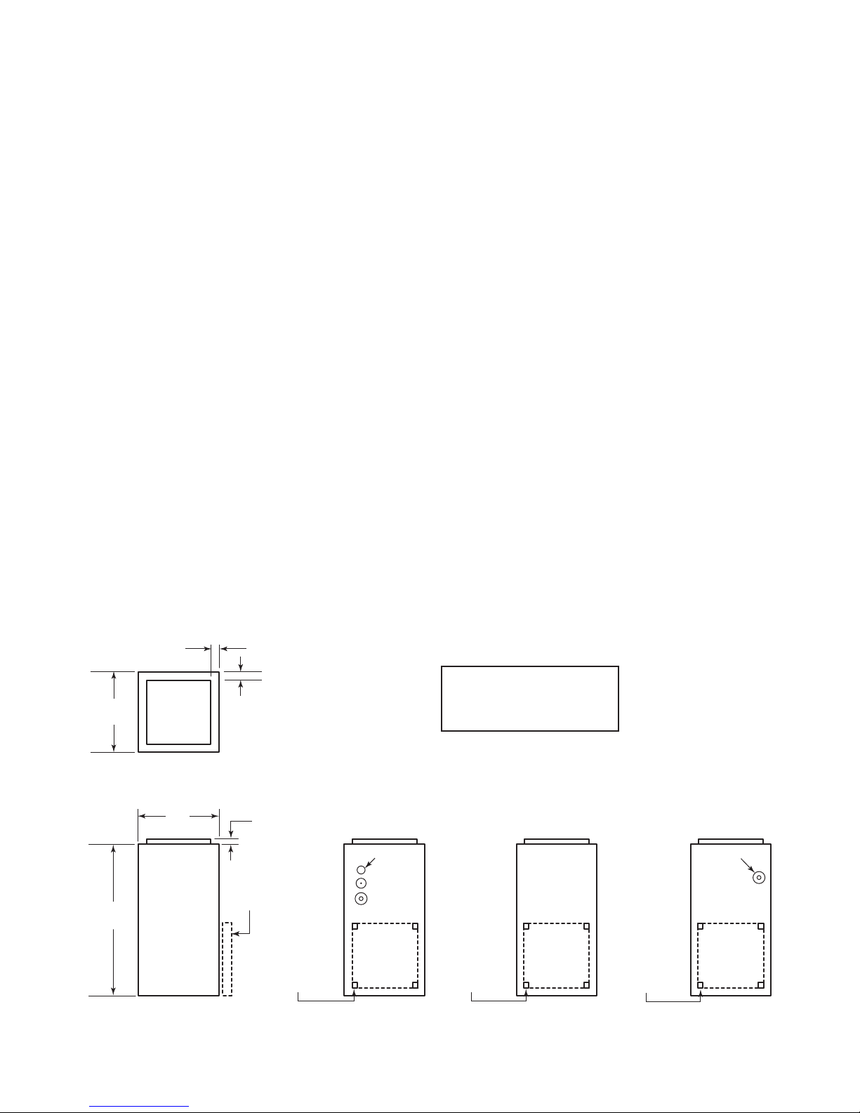
TABLE OF CONTENTS
1. DIMENSIONS .............................................................................................................................................. 3
2. GENERAL REQUIREMENTS AND SPECIFICATIONS ............................................................................... 4
3. OPERATING OPTIONS ............................................................................................................................... 5
4. BREAKERS ................................................................................................................................................. 5
5. INSTALLATION NOTES ............................................................................................................................... 6
5.1 COLD AIR RETURN ....................................................................................................................................................... 6
5.2 ELECTRICAL WIRING - POWER SUPPLY ............................................................................................................................6
5.3 C
6. USE IN MOBILE HOMES ............................................................................................................................ 6
7. USING OPTIONAL EQUIPMENT ................................................................................................................. 7
7.1 TWO-STA GE OR OUTDOOR THERMOSTAT .......................................................................................................................... 7
7.2 AIR CONDITIONING ....................................................................................................................................................... 7
7.3 ELECTRONIC AIR CLEANERS AND/OR POWERED FURNACE HUMIDIFIERS ................................................................................. 7
7.4 INTERLOCK CONNECTION ...............................................................................................................................................7
8. WIRING DIAGRAMS ................................................................................................................................. 8-9
9. SERVICE PARTS ........................................................................................................................................10
ONNECTING AND ADJUSTING THE LOW VOLTAGE THERMOSTAT ............................................................................................ 6
10. MAINTENANCE ..........................................................................................................................................11
11. TROUBLESHOOTING ................................................................................................................................11
12. WARRANTY ................................................................................................................................................12
1. DIMENSIONS
TOP VIEW
1½”
(38 mm)
WIRING KO’S VALUES
A = 1” (25 mm)
B = 1/4” (6 mm) & 1¼” (32 mm)
C = 1/2” (13 mm) & 1½” (38 mm)
18” x 18”
(457 mm x 457 mm)
1½” x 1½” KO
RETURN
1½” x 1½” KO
(38 mm x 38 mm)
WIRING KO’S
C
18” x 18”
(457 mm x 457 mm)
RETURN
FK0003A
20”
(508 mm)
39”
(991 mm)
17” x 17”
(432 mm x 432 mm)
DISCHARGE
1½”
(38 mm)
FRONT VIEW RIGHT SIDE VIEW REAR VIEW LEFT SIDE VIEW
20”
(508 mm)
1”
(25 mm)
FILTER FRAME
(EITHER SIDE, REAR
OR BOTTOM)
1½” x 1½” KO
(38 mm x 38 mm)
WIRING KO’S
A
B
C
18” x 18”
(457 mm x 457 mm)
RETURN
(38 mm x 38 mm)
- 3 -
2. GENERAL REQUIREMENTS AND SPECIFICATIONS
CAUTION
This unit must be installed in a dry place, in a non-corrosive, well-ventilated environment, without excessive dust. The
ambient temperatue must be over 10°C and under 27°C. If the ambient temperatue is 10°C or less, the plenum must be
insulated on 10 ft linear minimum length.
1. LOCATION - The furnace should be centrally located to the heating area.
2. POSITIONS - It can be installed for vertical, horizontal or downflow operation. When installed horizontally, the furnace should be positioned such as the
door will not end up being on the top. The door should be on the side of the furnace, to ensure that the motor bearings are in their designed position. In
vertical downflow installations, use only “L”- or “T”-shaped plenum with no openings or registers directly below furnace.
3. INSTALLATION CLEARANCES - As shipped from the factory, each unit is approved for “zero inch” clearance. If additional clearance is required, it will be
indicated on the data label attached to the furnace.
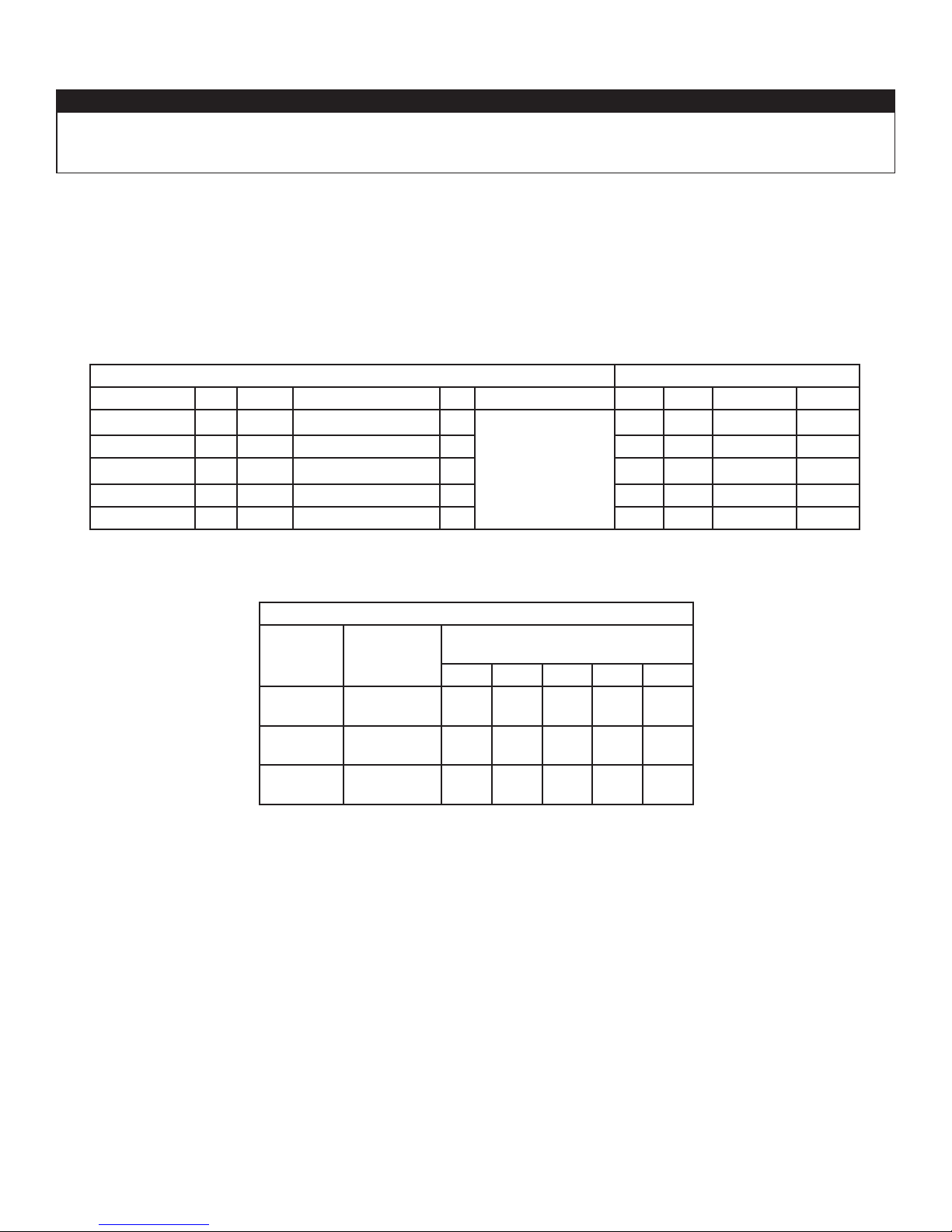
4. TEMPERATURE RISE - Furnaces are shipped to operate at 0.20” W.C. (50 Pa) external static pressure. They are certified for operation up to
0.50” W.C. (125 Pa). Check below for temperature rise table on specification chart and, if necessary, adjust the unit to match.
5. SERVICE CLEARANCE - Units are serviced from the FRONT. Leave at least 24” (610 mm) clearance in front of the door.
240 VOLTS - SINGLE PHASE TEMPERATURE RISE @ 0.20” W. C.
MODEL NO. KW BTHU AMPS INCL. MOTOR HP BLOWER
21ECM10 10 34152 43 1/3
21ECM15 15 51228 64 1/3 22 40 MEDIUM 903
21ECM18 18 61473 76 1/3 26 47 MEDIUM 903
10” x 8”
(254 mm x 203 mm)
21ECM20 20 68304 84 1/3 29 52 MEDIUM 903
21ECM23 22.5 76842 94 1/3 36 65 MEDIUM 903
°C °F *SPEED RPM
22 40 LOW 662
*FACTORY SETTINGS.
SUBJECT TO CHANGE WITHOUT NOTICE.
SPEED FLOW RATE
LOW**
MEDIUM
HIGH
** This speed can only be run with heater off, for cooling/ventilation purposes only.
10” x 8” (254 mm x 203 mm) BLOWER
STATIC PRESSURE
(INCHES OF WATER COLUMN)
0.2 0.3 0.4 0.5 0.6
CFM
L/s
CFM
L/s
CFM
L/s
684
323
1149
542
1238
584
582
275
110 4
521
1203
568
535
252
1064
502
1174
554
481
227
1016
479
1139
538
429
202
977
461
110 6
522
- 4 -
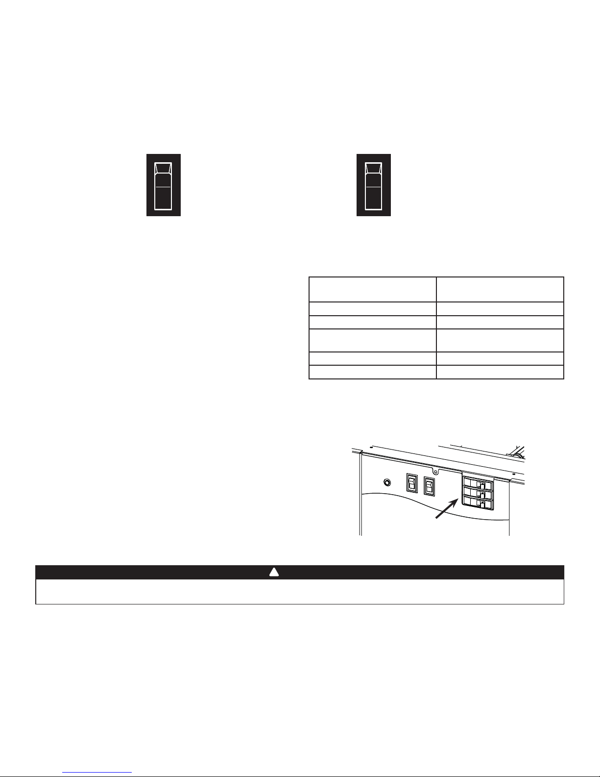
3. OPERATING OPTIONS
The furnace is shipped from the factory in a “Standard Heating Mode” (all switches are in the Down position). When the thermostat calls for heat, the automatic
controls will be activated and the furnace turned “ON”.
The blower will run at low speed or higher speed (as selected by SPEED SELECTOR switch).
As the furnace heats up, it automatically switches to the pre-programmed heating speed when additional elements are activated by the electronic control, if
it was initially set to run at low speed. The timing of this blower speed change will depend on whether FAST or SLOW is selected on the HEAT ACTIVATION switch.
You may, however, change from the Standard Heating Mode by using the controls built into your furnace.
SPEED SELECTOR
HIGH
LOW
The SPEED SELECTOR switch is used to control the fan speed (ventilation).
Even if there is no call for heat, the ventilation can be controlled by the
thermostat; the fan speed is determined by this switch.
LOW – The blower motor will operate at low speed.
HIGH – The blower motor will operate at a higher speed.
HEAT ACTIVATION
SLOW
FAST
During spring or fall, you may require less rapid response when the
thermostat calls for heat.
When SLOW is selected, it takes more time to bring all the elements online.
When FAST is selected, the heating elements come online faster.
Slow (First Stage)
Slow Response Sequence
Element 1 - Heat on instantly Element 1 - Heat on instantly
Blower on after a 3-second delay Blower on after a 3-second delay
Elements 3 and 5
after a 1-minute delay
Element 2 after a 2-minute delay Element 2 after a 20-second delay
Element 4 after a 3-minute delay Element 4 after a 30-second delay
NOTE: Elements 4 and 5 only where applicable.
Fast (Second Stage)
Rapid Response Sequence
Elements 3 and 5
after a 10-second delay
4. BREAKERS
ECM Series furnaces are equipped with breakers, located on the front
panel of the unit. These devices protect the heating elements from
overcurrent. If this situation occurs, the breakers will open to cut the power
from the heating elements only.
NOTE: The number of breakers varies according to the furnace
model; 21ECM10 model has no breakers, 21ECM15, 21ECM18
and 21ECM20 models have 2 breakers and 21ECM23 model has
3 breakers. Refer to Section 8 Wiring Diagrams.
BREAKERS
FD0001
!
WARNING
Breakers do not cut power to entire furnace, only to the heating elements. Do not use the breakers to turn off the furnace.
The power to the whole unit can only be cut from the main electrical panel.
- 5 -
5. INSTALLATION NOTES
5.1 COLD AIR RETURN
The duct can be attached to either side, rear or the bottom of the furnace.
For side return there are four 1½” (38 mm) knockouts which can be removed and used as an outline for cutting a 18” x 18” (457 mm x 457 mm)
return air opening in the furnace left or right side. Mount the filter frame to the furnace over the opening with the open side of the frame facing front.
Then attach the 19” x 19” (483 mm x 483 mm) air duct to the flanges on the filter frame.
For bottom mounting, remove the screws holding the bottom plate to the furnace, discard the bottom plate and attach the filter frame to the bottom
flanges with the open side of the frame facing front.
5.2 ELECTRICAL WIRING - POWER SUPPLY
The furnaces are completely factory wired. From a separate breaker, a two-wire plus ground supply wire is required. The ground conductor must be
firmly attached to the ground lug in the furnace and the supply wires to the terminal block in the furnace.
NOTE: When a FK120 ECM kit is used to supply an air cleaner and/or humidifier, a third (neutral) conductor must be brought into the furnace.
!
WARNING
For all installations, we only recommend appropriate gauge good quality copper wire(s). However, it is the electrician’s
responsibility to ensure that the wiring and connections are compliant to the latest editions of the Canadian Electrical Code
and local codes.
5.3 CONNECTING AND ADJUSTING THE LOW VO LTAGE T HERMOSTAT (Use only class 1 wires inside furnace compartments.)
Attach thermostat wires to the low voltage terminal block located on the inside of the furnace. Follow the diagrams supplied with the thermostat. As a
general guide, remember that the R & W terminals control single stage heating; the R & Y terminals control cooling. Single stage cooling uses “Y/Y2”
as first and only stage.Two-stage cooling uses “Y1” as first stage and “Y/Y2” as second stage. Make sure the thermostat is levelled on the wall and in
appropriate location as per instructions supplied with the thermostat.
CAUTION
Before turning the furnace on, the heat anticipator in the thermostat must be properly set.
Because each installation is different an accurate reading of the current draw should be made with an AC meter. Set the meter at 2 A range for
furnaces through 20 kW, and at 4 A range for larger units.
A. Set the anticipator at its highest setting.
B. Disconnect the “W1” thermostat wire from the furnace low voltage terminal connections.
C. Connect the AC meter between the “W1” terminal on the board and the loose “W1” wire.
D. Turn the thermostat up to start the furnace and allow it to run,with all elements on, for three or four minutes.
E. Read the current draw on the meter and reset the anticipator to match the meter reading.
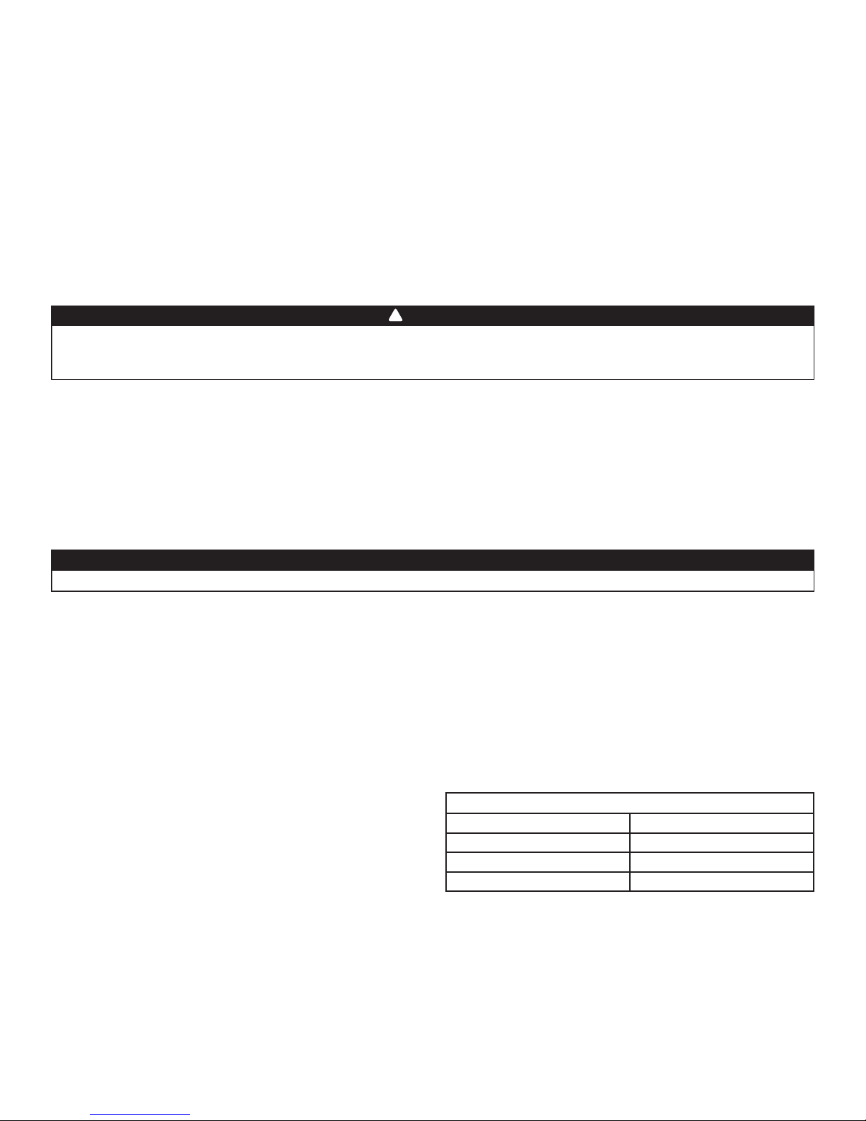
6. USE IN MOBILE HOMES
Models 21ECM10, 21ECM15, 21ECM18 & 21ECM20 are certified for
“L”-shape and “T”-shape shallow duct installation with model FSB-1 sub-base
in downflow applications when the supply air ducts pass through the
floor of the structure. Recommended size of a floor opening: 14¼” x 14¼”
(362 mm x 362 mm). The duct system must be designed so that the external
static pressure of the system does not exceed the maximum external static
pressure of 0.50” W.C. (125 Pa).
SHALLOW DUCT AREA REQUIREMENTS
DUCT DEPTH DUCT WIDTH
4” (102 mm) 16” (406 mm)
5” (127 mm) 13” (330 mm)
6” (152 mm) 10” (254 mm)
- 6 -

7. U SING OPTIONAL EQUIPMENT
7.1 TWO-STAG E OR OUTDOOR T HERMOSTAT
(The HEAT ACTIVATION switch must be in the SLOW position).
Follow the directions supplied with the two-stage or outdoor thermostat in conjunction with the furnace wiring diagram.
7.2 AIR CONDITIONING
Your furnace is equipped with all the controls required for the addition
of air conditioning (except the heat-cool thermostat).
The evaporator coil may be installed by a local contractor in sheet
metal plenum of his own manufacture. The coil should be located:
centred over the “chimney” of the furnace 4” (102 mm) to 6” (152 mm)
above the top of the furnace.
Make sure no air is allowed to bypass the cooling coil during cooling
operation. If the discharge opening is a great deal larger than the
coil, and the ductwork is correspondingly larger than the coil, you
may want to use a bypass damper for heating. The damper would be
closed in summer, directing all air flow through the coil. In winter the
damper would be open to allow air to bypass the coil.
Typical air-conditioning field wiring connections are shown in the
diagram at right.
FURNACE
FE0001A
WIRING COLOR CODE
CGRW1W2 Y
COMMON GREEN RED WHITE
THERMOSTAT
WHITE (BLUE
OPTIONAL)
CONDENSER
YELLOW
7.3 ELECTRONIC AIR CLEANERS AND/OR POWERED FURNACE HUMIDIFIERS
These units operate at 120 V. Your 240 V furnace is designed so that Model FK120 ECM adaptor kit can be mounted inside the furnace to supply the
required 120 V. Instructions for mounting and wiring are included with the kit.
7.4 INTERLOCK CONNECTION
When the electric furnace is used in combination with another device
(as for example, a wood burning furnace), it is recommended to perform
the connection by referring to the wiring diagram at right. The burning
furnace thermostat will then turn automatically on the blower in the
electric furnace.
External Request
for Fan Activation
Relay
COM
FE0034A
NC
NO
Furnace
Thermostat
R
G
Electric Furnace
Furnace
24 VAC
R
Power Output
Call for FAN
G
System
- 7 -
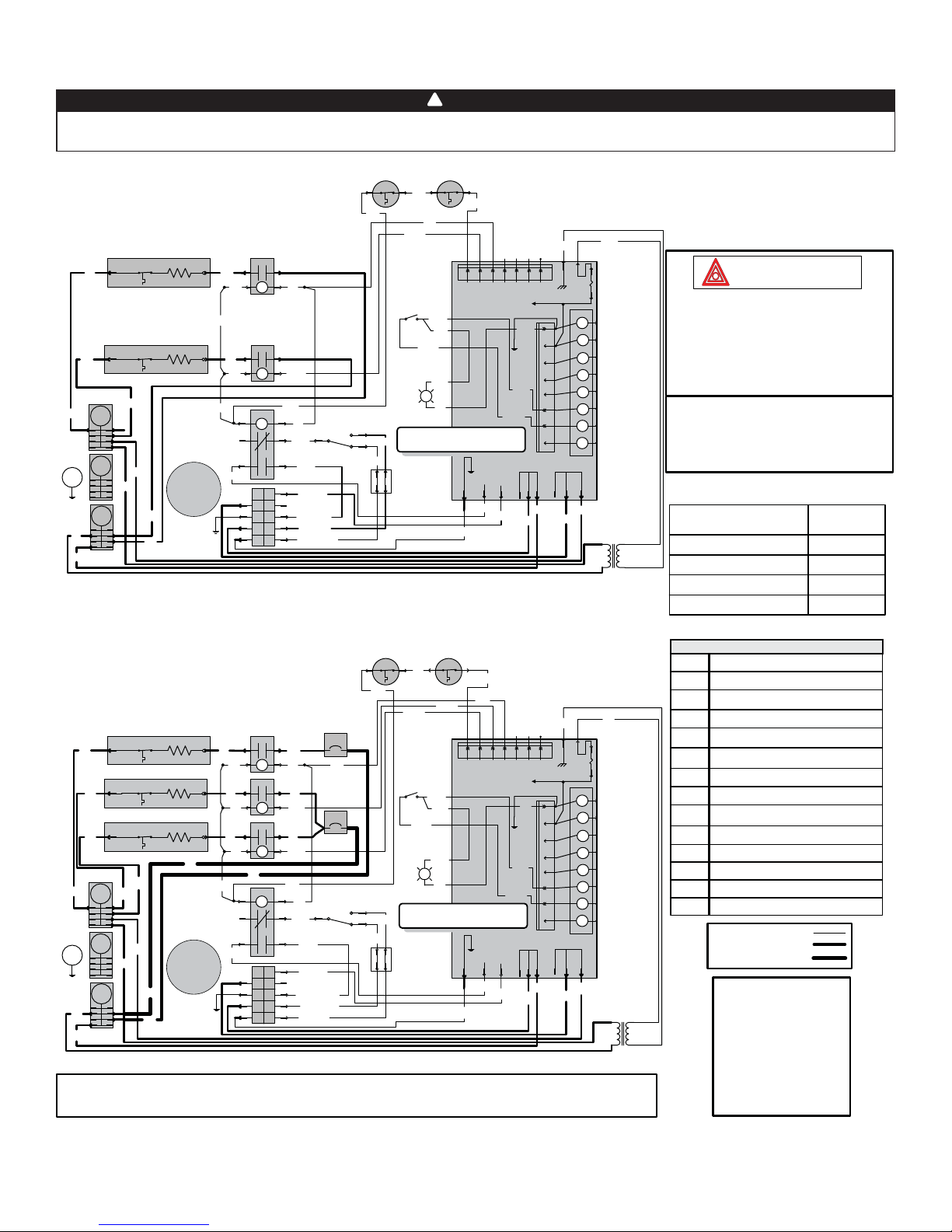
8. WIRING DIAGRAMS
!
WARNING
Risk of electric shock. Disconnect power before installation, servicing, maintenance or field wiring. Replace all panels
before operating. Failure to do so can result in electric shock causing severe injuries or death.
21ECM10 Model
E
R
R
R
G
B
B
ARTP
HEAT 2
W
E
ARTP
HEAT 1
R
L2
N
R
C=COM
R
L1
L=LINE
G=GROUND
N=NEUTRAL
B
W
M
1=MED
2=LOW
3=LOW
4=HI
5=HI
B
B
NC
HEAT 2
KC2
NO
COM
24V
W
NO
B
W
O
M
HEAT 1
KC1
3
4
6
N
G
L
C
P
DC
COM
24V
GR
DC
W
K7
1
24V
DC
5
4
3
2
1
5
2
P
BL
BL
B (HI)
NC
BL (LO)
R (MED)
Y (LO)
Speed Selector
Open: 93.3°C
MRTP 1 MRTP 2
W
Heat Activation
INDICATOR
LO
R
MED
Y
TB
W
P
GR
PP
PP
GR
HEAT
PP
B
10 KW 240 VAC
Single phase
W
Power
Heat 2
Heat 1
1234567
BOARD POWER SUPPLY
X13 COM
X13 HEAT
O
W
Vout
Heat 3
Heat 4
P3
BLK
PP
GR
L1
XFMR
X13 COOL
B
B
B
GND
P2-8
P2-7
P2-6
P2-5
P2-4
P2-3
P2-2
P2-1
P2
L1
W
L2
L2 COM
R
Y
F1
24VAC
5 AMPS
24 VAC
COMMON OUT
FUSED 24 VAC
POWER OUT
GRC
CALL FOR FAN
Y/Y2
CALL FOR COOL
REVERSING VALVE
CALL FOR HEAT 1
CALL FOR HEAT 2
Y1W2W1O
CALL FOR COOL 1
P1
L2
R
Class 2 Transformer
Pri: 240 V 60 Hz
Sec: 24 V 60 Hz 40 VA
R
B
T
21ECM15 Model
Open: 93.3°C
MRTP 1 MRTP 2
W
W
GR
HEAT 3
E
R
R
R
ARTP
ARTP
ARTP
HEAT 3
E
HEAT 2
E
HEAT 1
B
R
G
B
R
L2
R
N
R
R
L1
M
1=LO
C=COM
2=MED HI
L=LINE
3=MED HI
G=GROUND
4=HI
N=NEUTRAL
B
5=HI
B
KC3
COM
NO
B
24V
W
DC
HEAT 2
KC2
COM
NO
B
24V
W
DC
HEAT 1
KC1
NO
B
W
NC
COM
24V
W
DC
B
K7
1
3
24V
DC
5
4
2
6
O
5
M
4
N
3
G
2
L
1
C
B2
25 A
R
PP
R
B1
BR
50 A
R
GR
W
Speed Selector
P
BL
LO
MED
BL
B (HI)
NC
BL (MED)
Y (MED)
R (LO)
Heat
Activation
PP
GR
HEAT
INDICATOR
R
15 KW 240 VAC
Y
TB
B
For the use of a two-stage thermostat or an outdoor thermostat, connect between W1 and W2.
Make sure that the Heat Activation switch is set to “Slow” position.
FE0049A
W
P
BR
Power
Heat 1
1234567
BOARD POWER SUPPLY
PP
PP
B
Single phase
X13 COM
X13 HEAT
O
W
Heat 2
Heat 3
P3
X13 COOL
B
Heat 4
PP
GR
XFMR
B
B
Vout
L1
B
GND
P2-8
P2-7
P2-6
P2-5
P2-4
P2-3
P2-2
P2-1
P2
L1
W
L2
L2 COM
R
Y
F1
24VAC
5 AMPS
C
24 VAC
COMMON OUT
FUSED 24 VAC
POWER OUT
GR
CALL FOR FAN
Y/Y2
CALL FOR COOL
REVERSING VALVE
CALL FOR HEAT 1
CALL FOR HEAT 2
Y1W2W1O
CALL FOR COOL 1
P1
L2
R
Class 2 Transformer
Pri: 240 V 60 Hz
Sec: 24 V 60 Hz 40 VA
R
B
T
Critical characteristic
1. If any of the original wire, as supplied, must
be replaced, use the same equivalent wire.
Wiring must comply with applicable codes,
ordinances and regulations.
2. Field wiring must comply with applicable
codes, ordinances and regulations. Use only
Class 1 wiring inside furnace compartments.
Line voltage wiring:
UL AWM 1015/1230, 600V, 105°C, VW-1, 12 AWG;
CSA TEW 600V, 105°C, FT1, 12 AWG.
Low voltage wiring:
same ratings as high voltage except 18 AWG.
FAN MOTOR SPEED
Y
Y
HI
MED
MED
LOW
LEGEND
C
Capacitor
E
Heating Element
KC
Heating Element Relay
K
Fan Relay
ARTP
Auto-Reset Thermal Protector
MRTP
Manual-Reset Thermal Protector
M
Fan Motor
TB
Terminal Block
T
Transformer Class 2
HEAT
Heat
L1, L2
240 V Line Supply
N
Neutral
COLOR
BLACK
BLUE
YELLOW
RED
F1 Fuse
B Breaker
Low power
High power
High power 8 AWG
WIRING COLOR CODE
B BLACK
Y
Y
BL BLUE
BR BROWN
GR GREY
O ORANGE
P PINK
PP PURPLE
R RED
W WHITE
Y YELLOW
- 8 -
 Loading...