

Broan HRV100H, HRV200H, ERV100HC, ERV200HC, 1001 ERV Installer Manual
...
INSTALLER MANUAL
VENTILATION SYSTEMS
VB0065
vänEE Canadian Model Numbers
1001 ERV
1001 HRV*
2001 ERV
2001 HRV*
READ AND SAVE THESE INSTRUCTIONS
Broan U.S.A. Model Numbers
HRV100H
HRV200H
ERV100HC
ERV200HC
* These products earned the ENERGY STAR® by meeting strict energy efficiency
guidelines set by Natural Resources Canada and the US EPA. They meet
ENERGY STAR requirements only when used in Canada.
03119 rev. 09

TABLE OF CONTENTS
1. SERVICE ........................................................................................................................................................3-4
1.1 3-D DRAWING ............................................................................................................................................................3
1.2 PARTS ORDERING CHART .............................................................................................................................................4
1.3 T
2. UNIT TYPE & DEFROST SETTING VS GEOGRAPHICAL LOCATION .................................................................................. 5
3. T
3.1 AIR DISTRIBUTION (NORMAL OPERATION) ........................................................................................................................6
3.2 AIR DISTRIBUTION (DEFROST MODE) ..............................................................................................................................6
3.3 DEFROST CYCLE TABLE..................................................................................................................................................6
3.4 DIMENSIONS ...............................................................................................................................................................7
3.5 C
3.6 S
4. TYPICAL INSTALLATIONS .......................................................................................................................................8
4.1 FULLY DUCTED SYSTEM ................................................................................................................................................8
4.2 EXHAUST DUCTED SYSTEM (SOURCE POINT VENTILATION) .................................................................................................8
4.3 SIMPLIFIED (VOLUME VENTILATION) .................................................................................................................................8
5. INSTALLATION ................................................................................................................................................ 9-14
5.1 LOCATING AND MOUNTING THE UNIT ...............................................................................................................................9
5.2 PLANNING OF THE DUCTWORK .......................................................................................................................................9
5.3 CALCULATING THE DUCT SIZE ...................................................................................................................................... 10
5.3.1 EXAMPLE OF CALCULATION ...................................................................................................................................................10
5.3.2 E
5.4 INSTALLING THE DUCTWORK AND REGISTERS .................................................................................................................. 11
5.4.1 FULLY DUCTED SYSTEM.......................................................................................................................................................11
5.4.2 E
5.4.3 S
5.5 CONNECTING DUCT TO THE UNIT .................................................................................................................................13
5.6 INSTALLING EXTERIOR HOODS ...................................................................................................................................... 14
5.7 CONNECTING THE DRAIN .............................................................................................................................................14
6. CONTROL DEVICES ...................................................................................................................................... 15-16
6.1 MAIN CONTROLS .......................................................................................................................................................15
6.2 OPTIONAL CONTROLS .................................................................................................................................................16
6.3 OTHER FEATURES ......................................................................................................................................................16
6.4 MAIN AND OPTIONAL CONTROLS AVAILABLE FOR YOUR UNIT .............................................................................................16
7. I NSTALLATION OF THE CONTROLS .....................................................................................................................17-20
7.1 DIMENSIONS AND SPECIFICATIONS (MAIN CONTROLS) ......................................................................................................17
7.2 INSTALLATION OF THE MAIN CONTROL ....................................................................................................................... 17-19
7.2.1 PLATINUM MAIN CONTROL INSTALLATION .................................................................................................................................17
7.2.2 D
7.2.3 D
7.2.4 M
7.3 ELECTRICAL CONNECTION TO OPTIONAL CONTROLS ........................................................................................................19
7.4 E
8. WIRING DIAGRAMS ...................................................................................................................................... 21-22
9. A
9.1 WHAT YO U NEED TO BALANCE THE UNIT .......................................................................................................................23
9.2 PRELIMINARY STAGES TO BALANCE THE UNIT .................................................................................................................23
9.3 INSTALLATION OF FLOW COLLARS OR "FLOW MEASURING STATIONS" ...................................................................................23
9.4 BALANCING PROCEDURE .............................................................................................................................................24
10. OVERALL VERIFICATION ................................................................................................................................ 25-26
10.1 MAIN CONTROLS .......................................................................................................................................................25
10.2 OPTIONAL CONTROL ..................................................................................................................................................26
11. MAINTENANCE/INSTRUCTIONS FOR USER .............................................................................................................. 26
12. T
13. R
ECHNICAL SUPPORT ...................................................................................................................................................4
ECHNICAL DATA ............................................................................................................................................. 6-7
ONTROLS AND FURNACE LINK OPTION ...........................................................................................................................7
PECIFICATIONS ...........................................................................................................................................................7
XAMPLE OF A DESIGN FOR A FULLY DUCTED SYSTEM .............................................................................................................10
XHAUST DUCTED SYSTEM (SOURCE POINT VENTILATION) ........................................................................................................11
IMPLIFIED INSTALLATION (VOLUME VENTILATION) .....................................................................................................................12
ECO-TOUCH MAIN CONTROL INSTALLATION ...........................................................................................................................18
EHUMIDISTAT, DH100W, VT1W AND VT2W MAIN CONTROL INSTALLATION ..............................................................................18
AIN CONTROL ELECTRICAL CONNECTION ..............................................................................................................................19
LECTRICAL CONNECTION TO THE FURNACE ...................................................................................................................20
IR FLOW BALANCING .................................................................................................................................23-24
ROUBLESHOOTING ...................................................................................................................................... 27-28
EFERENCES .................................................................................................................................................. 28
2

ABOUT THIS MANUAL
This manual uses the following symbols to emphasize particular information:
!
WARNING
Identifies an instruction which, if not followed, might cause serious personal injuries including possibility of
death.
CAUTION
Denotes an instruction which, if not followed, may severely damage the unit and/or its components.
NOTE: Indicates supplementary information needed to fully complete an instruction.
!
WARNING
Installation work and electrical wiring must be done by a qualified person(s) in accordance with all applicable
codes and standards, including fire-rated construction codes and standards.
1. SERVICE
1.1 3-D DRAWING
DAMPER ASSEMBLY (REAR VIEW)
23
6
1
4
5
7
8
2
3
20
9
10
11
15
12
26
25
24
23
22
21
19
18
3
VL0016
13
14
16
17
3
1. SERVICE (CONT'D)
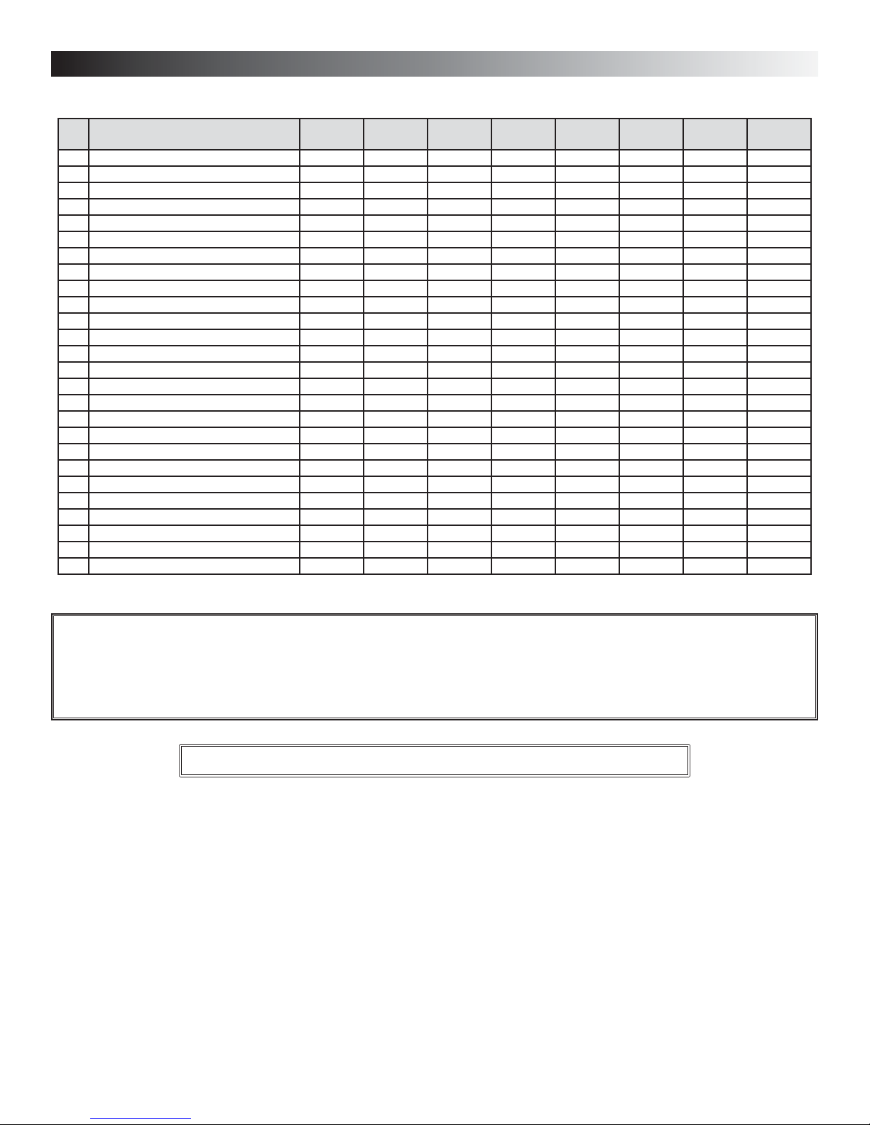
1.2 PARTS ORDERING CHART
NO.DESCRIPTION
1DOUBLE COLLAR PORT NO. 2 00866 00866 00866 00866 00866 00866 00866 00866
ING NUT NO. 10-32 00874 00874 00874 00874 00874 00874 00874 00874
2W
3B
ALANCING DOUBLE COLLAR PORT 02256 02256 02256 02256 02256 02256 02256 02256
4INLET RING 12913 12913 12913 12913 12913 12913 12913 12913
OP WHEEL 14307 03093 14308 03093 14307 03093 14308 03093
5T
6ELECTRONIC BOARD V99 13507 13507 13507 13507 13508 13507 13508 13507
7MOTOR ASSEMBLY 13504 13555 13556 13506 13504 13555 13505 13506
8BOTTOM WHEEL 02015 02015 03093 03093 02015 02015 03093 03093
9SQUARE BALANCING DAMPER 12645 12645 12645 12645 12645 12645 12645 12645
10 DOOR LATCHES (LATCH) 00886 00886 00886 00886 00886 00886 00886 00886
11 D RAIN CONNECTOR 02418 02418 02418 02418 02418 02418 02418 02418
12 DRAIN GASKET 0.625" D 02419 02419 02419 02419 02419 02419 02419 02419
ASHER 5/8" ID X 1" OD 03117 03117 03117 03117 03117 03117 03117 03117
13 W
14 NUT 5/8-18 02420 02420 02420 02420 02420 02420 02420 02420
15 RECOVERY CORE 03132 03136 03133 03137 03134 03136 03135 03137
16 DOOR ASSEMBLY 12644 12644 12644 12644 12648 12648 12648 12648
17 DOOR LATCHES (KEEPER) 00887 00887 00887 00887 00887 00887 00887 00887
18 HINGE ASSEMBLY 00672 00672 00672 00672 00672 00672 00672 00672
19 FILTER 03096 03096 03097 03097 03096 03096 03097 03097
20 SWITCH E69 10A 01825 01825 01825 01825 01825 01825 01825 01825
21 DAMPER ASSEMBLY NO. 2 12643 12643 12649 12649 12643 12643 12649 12649
22 PLASTIC BALANCING DAMPER 02253 02253 02253 02253 02253 02253 02253 02253
AMPER ROD 12620 12620 12620 12620 12620 12620 12620 12620
23 D
24 DOUBLE COLLAR PORT NO. 5 02021 02021 02021 02021 02021 02021 02021 02021
25 DAMPER NO. 1 12459 12459 12459 12459 12459 12459 12459 12459
26 DAMPER ACTUATOR ASSEMBLY 03124 03124 03124 03124 03124 03124 03124 03124
1001
HRV
1001
ERV
2001
HRV
2001
ERV
HRV
100H
ERV
100HC
HRV
200H
ERV
200HC
Please note that parts not listed are not available; those parts require assembly knowledge that only manufacturer can guarantee.
REPLACEMENT PARTS AND REPAIRS
In order to ensure your ventilation unit remains in good working condition, you must use the manufacturer genuine replacement parts
only. The manufacturer replacement parts are specially designed for each unit and are manufactured to comply with all the applicable
certification standards and maintain a high standard of safety. Any third party replacement part used may cause serious damage and
drastically reduce the performance level of your unit, which will result in premature failing. The manufacturer recommends to contact a
certified service depot for all replacement parts and repairs.
TO ORDER PARTS: Contact your local distributor.
1.3 TECHNICAL SUPPORT (FOR ASSISTANCE)
For assistance, call on weekdays, from 8:30 a.m. to 5:00 p.m. (Eastern Standard Time).
NOTE: Do not call these numbers for ordering parts.
Technical Support Department
Canada: 1-888-908-2633 (for distributors only)
U.S.A.: 1-800-637-1453
4

2. UNIT TYPE AND DEFROST SETTING VS GEOGRAPHICAL LOCATION
ST JOHN'S
GOOSE BAY
CHARLOTTETOWN
BATHURST
QUEBEC
HALIFAX
ST-JOHN
BOSTON
SEPT-ILES
LABRADOR CITY
GASPÉ
MATANE
SOLUTION
SYMPTOM
(CONDENSATION)
ERV
ERV
HRV
YELLOWKNIFE
FORT SMITH
HAY RIVER
FORT MCMURRAY
ZONE A
PRINCE ALBERT
EDMONTON
GRANDE PRAIRIE
JASPER
SASKATOON
KAMLOOPS
CHIBOUGAMAU
WINNIPEG
REGINA
CALGARY
PENTICTON
CHICOUTIMI
VAL-DOR
TIMMINS
ZONE B
HELENA
LETHBRIDGE
MONTRÉAL
OTTAWA
NORTH BAY
SUDBURY
SAULT STE MARIE
ST. PAUL
BISMARCK
TORONTO
DETROIT
MADISON
DES MOINES
ZONE C
SALT LAKE CITY
BOISE
HARTFORD
HARRISBURG
COLUMBUS
INDIANAPOLIS
SPRINGFIELD
DENVER
RENO
WASHINGTON
TOPEKA
RALEIGH
COLUMBIA
NASHVILLE
OKLAHOMA CITY
SANTA FE
ATLANTA
ZONE D
PHOENIX
BATON ROUGE
AUSTI N
ZONE C SELECTION CHART
INDOOR AIR QUALITY PROBLEM
AND/OR EXCESS MOISTURE PROBLEM
particular problems)
AND/OR IMPORTANT EXCESS MOISTURE PROBLEM
Prince Rupert
JUNEAU
WHITEHORSE
ANCHORAGE
VICTORIA
OLYMPIA
SALEM
ZONE C (HRV or ERV according to your client’s
See ZONE C SELECTION CHART at right.
• HRV MODELS: 1001 HRV, 2001 HRV, HRV100H, HRV200H
• ERV MODELS: 1001 ERV, 2001 ERV, ERV100HC, ERV200HC
ZONE D (ERVs recommended)
SACRAMENTO
VN0002
ZONE A (HRVs only)
• Set Extended Defrost according to section 7.2.3, point 4
• MODELS: 1001 HRV, 2001 HRV, HRV100H, HRV200H
ZONE B (HRVs only)
• ERV MODELS: 1001 ERV, 2001 ERV, ERV100H, ERV200H
strategy pre-set)
• Extended Defrost setting not required (factory defrost
• MODELS: 1001 HRV, 2001 HRV, HRV100H, HRV200H
5
3. TECHNICAL DATA
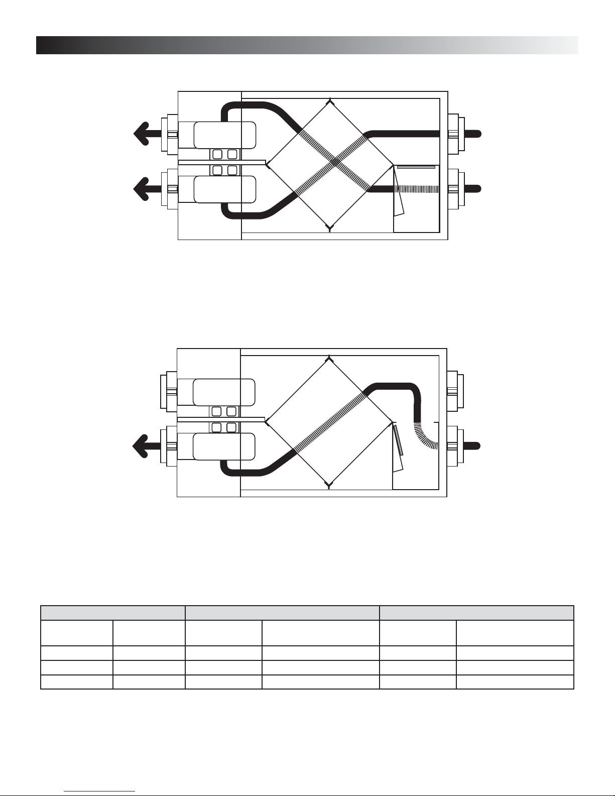
3.1 AIR DISTRIBUTION (NORMAL OPERATION)
STALE AIR
TO OUTSIDE
FRESH AIR
TO BUILDING
VF0013
3.2 AIR DISTRIBUTION (DEFROST MODE)
FRESH AIR
FROM OUTSIDE
STALE AIR
FROM BUILDING
FRESH AIR
TO BUILDING
VF0020
3.3 D
NOTE: The unit performance charts are listed on their own specification sheets. To access those documents,
EFROST CYCLE TABLE
OUTSIDE TEMPERATURE DEFROST CYCLES EXTENDED DEFROST CYCLE
CELCIUS (°C) FAHRENHEIT (°F) DEFROSTING (MIN.)
OPERATION TIME (MIN.)
BETWEEN EACH DEFROST CYCLE
DEFROSTING (MIN.)
-5 23 6 32 10 30
-1556 321020
-27 -17 6 20 10 15
visit: www.vanee-ventilation.com (Canadian units) or www.broan.com (U.S.A. units).
STALE AIR
FROM BUILDING
OPERATION TIME (MIN.)
BETWEEN EACH DEFROST CYCLE
6
3. TECHNICAL DATA (CONT'D)
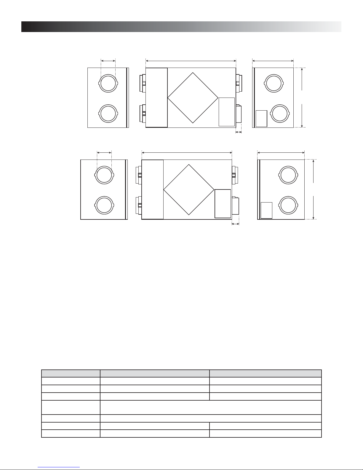
3.4 DIMENSIONS
Models:
• 1001 ERV
• 1001 HRV
• HRV100H
• ERV100HC
Models:
• 2001 ERV
• 2001 HRV
• HRV200H
• ERV200HC
VK0040A
6" (152mm)
6" (152mm)
30¼" (768mm)
30¼" (768mm)
13¾" (349mm)
20"
(508mm)
2½" (63mm)
19" (483mm)
20"
(508mm)
VK0039A
3.5 CONTROLS AND FURNACE LINK OPTION
Main controls:
• Platinum (Canada only)
• Deco-Touch (Canada only)
• VT1W (U.S.A. only)
• VT2W (U.S.A. only)
Optional controls:
• 20-minute push-button (for HRV100H and
HRV200H models only)
• 20/40/60-minute push-button
(for all other models)
• 60-minute crank timer
• Dehumidistat
3.6 SPECIFICATIONS
MODELS 1001 ERV, 1001 HRV, HRV100H, ERV100HC 2001 ERV, 2001 HRV, HRV200H, ERV200HC
WEIGHT 65 LB. (30 KG) 73 LB. (33 KG)
PORT DIAMETER 6” (152 MM) 6” (152 MM)
DRAIN DIAMETER 1/2” (12 MM) 1/2” (12 MM)
NSTALLATION CHAINS, SPRING AND HOOKS (PROVIDED WITH U.S.A. UNITS)
I
M
OTOR SPEED HIGH AND LOW SPEEDS FACTORY SET (OPTIONAL INCREASED LOW SPEED - BLUE WIRE)
ELECTRICAL SUPPLY 120 V, 60 HZ 120 V, 60 HZ
POWER CONSUMPTION 150 WATTS 225 WATTS
2½" (63mm)
Link option:
• Furnace interlock
(use with forced air systems)
TRAPS AND WASHERS (PROVIDED WITH CANADIAN UNITS)
S
7
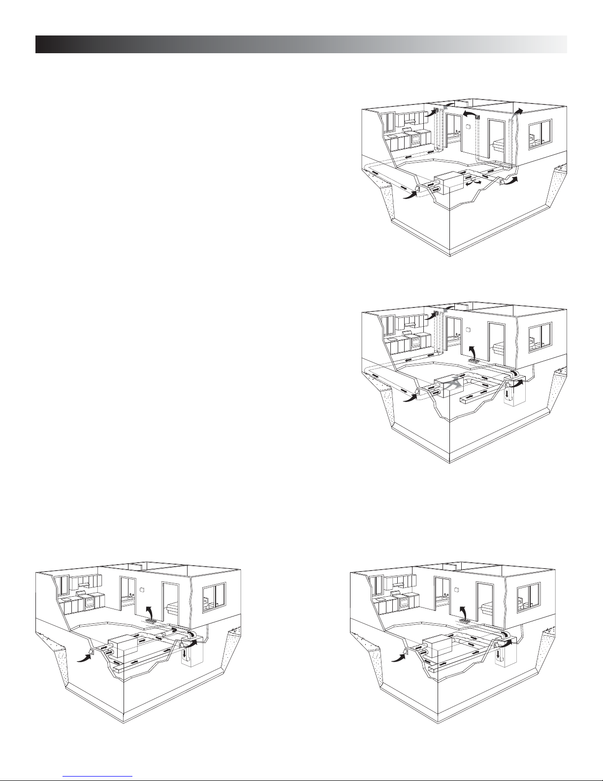
4. TYPICAL INSTALLATION
There are three common installation methods.
4.1 FULLY DUCTED SYSTEM
(Primarily for homes with radiant hot water or electric baseboard heating. See
Figure at right.)
Moist, stale air is exhausted from the high humidity areas in the home, such as
bathrooms, kitchen and laundry room. Fresh air is supplied to bedrooms and
principal living areas.
If required, bathroom fans and a range hood may be used to better exhaust stale
air.
Homes with more than one level require at least one exhaust register at the
highest level.
VH0024
4.2 EXHAUST DUCTED SYSTEM (SOURCE POINT VENTILATION)
(For homes with forced air heating. See Figure at right.)
Moist, stale air is exhausted from the high humidity areas in the home, such as
bathrooms, kitchen and laundry room. Fresh air is supplied to the cold air return or
the supply duct of the furnace.
If required, bathroom fans and a range hood may be used to better exhaust stale air.
Homes with more than one level require at least one exhaust register at the highest
level.
NOTE: For this type of installation, it is not essential that the furnace blower runs
when the unit is in operation, but we recommend it.
VH0025
4.3 SIMPLIFIED (VOLUME VENTILATION)
(For homes with forced air heating. See Figures A and B below.)
Fresh air and exhaust air flow through the furnace ducts which simplifies the installation.
The use of bathroom fans and range hood is suggested to better exhaust stale air.
NOTE: For the installation type shown in Figure B, furnace blower should be running when the unit is in operation.
See 5.4.1
for details
See 5.4.2
for details
VH0027
See 5.4.3
for details
AB
OR
VH0026
See 5.4.3
for details
8
5. INSTALLATION
!
WARNING
When applicable local regulations comprise more restrictive installation and/or certification requirements, the
aforementioned requirements prevail on those of this document and the installer agrees to conform to these at
his own expenses.
!
WARNING
When performing installation, servicing or cleaning the unit, it is recommended to wear safety glasses and gloves.
INSPECTING THE BOX CONTENT
• Inspect the exterior of the unit for shipping damage. Ensure that there is no damage to the door, door latches, door hinges, dampers,
duct collars, cabinet, etc.
• Inspect the interior of the unit for damage. Ensure that the fan motor assembly, recovery core, insulation, dampers, damper actuator
and drain pan are all intact.
• If the unit was damaged during shipping, contact your local distributor. (Claims must be made within 24 hours after delivery.)
• Use checklist included with the unit to ensure that no parts are missing.
5.1 LOCATING AND MOUNTING THE UNIT
Choose an appropriate location for the unit:
• Within an area of the house where the temperature is kept above 10°C/50°F and below
40°C/104°F
• Away from living areas (dining room, living room, bedroom), if possible.
• So as to provide easy access to the interior cabinet for every three months and annual
maintenance, and to the control panel on the right hand side of the unit.
• Close to an exterior wall, so as to limit the length of the insulated flexible duct to and from
the unit.
• Close to a drain. If no drain is close by, use a pail to collect run-off.
• Away from hot chimneys, electrical panel and other fire hazards.
• Allow for a power source (110 V standard outlet).
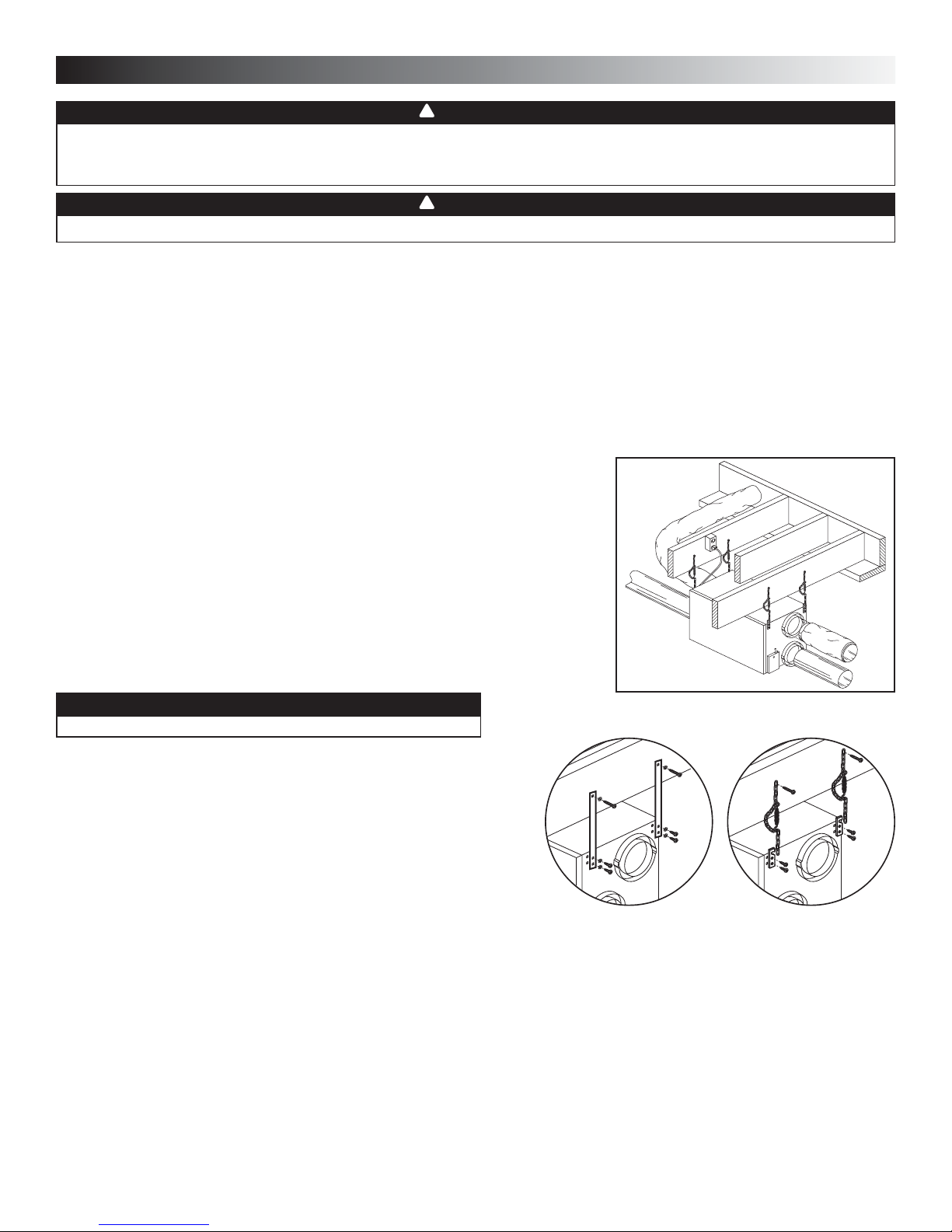
VD0064
CAUTION
Make sure the unit is level.
For vänEE Canadian models 1001 VRE, 1001 VRC, 2001 VRE and 2001 VRC,
hang the unit to ceiling joists with washers and 4 straps (included) (see figure
at right).
For Broan U.S.A. models HRV100H, HRV200H, ERV100HC, and ERV200HC,
hang the unit to ceiling joists with the 4 chains, springs and hooks (included)
(see figure at right).
VD0212
VÄN EE CANADIAN MODELS
1001 ERV, 1001 HRV,
2001 ERV AND 2001 HRV
BROAN U.S.A. MODELS
HRV100H, HRV200H,
ERV100HC AND ERV200HC
5.2 PLANNING THE DUCTWORK
a) Follow the instructions in Section 5.3 on next page to determine the appropriate duct diameters for your system.
b) Keep it simple. Plan for a minimum number of bends and joints. Keep the length of insulated duct to a minimum.
c) Do not use wall cavities as ducts. Do not use branch lines smaller than 4” (102 mm) Ø.
d) Do not ventilate crawl spaces or cold rooms. Do not attempt to recover the exhaust air from a dryer or a range hood. This would cause
clogging of the recovery module. Use sheet metal for the kitchen exhaust duct.
e) Be sure to plan for at least one exhaust register on the highest lived-in level of the house if it has 2 floors or more.
9
 Loading...