

Page 1
Service Documentation Market Release 7/84
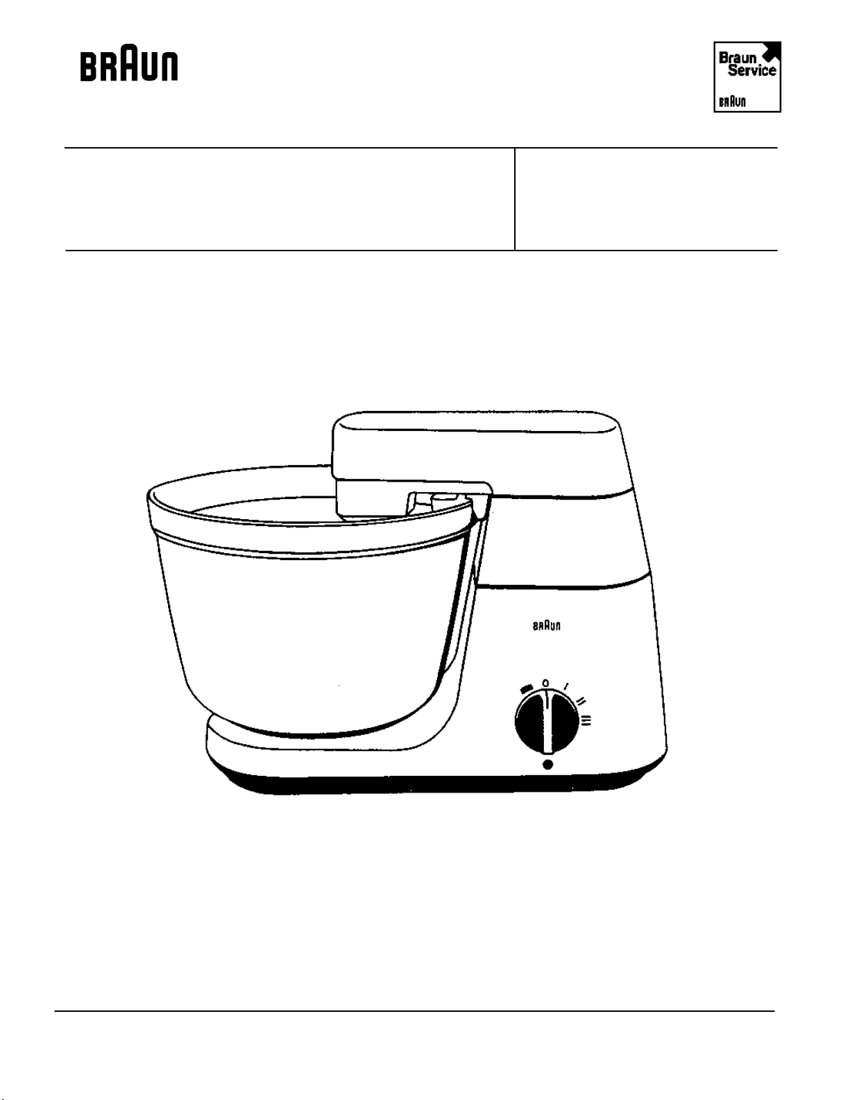
Braun Kitchen machine KM 32 B 4209
with lamp
4209
Page 2

BINC Rev: 7/96 Service Documentation
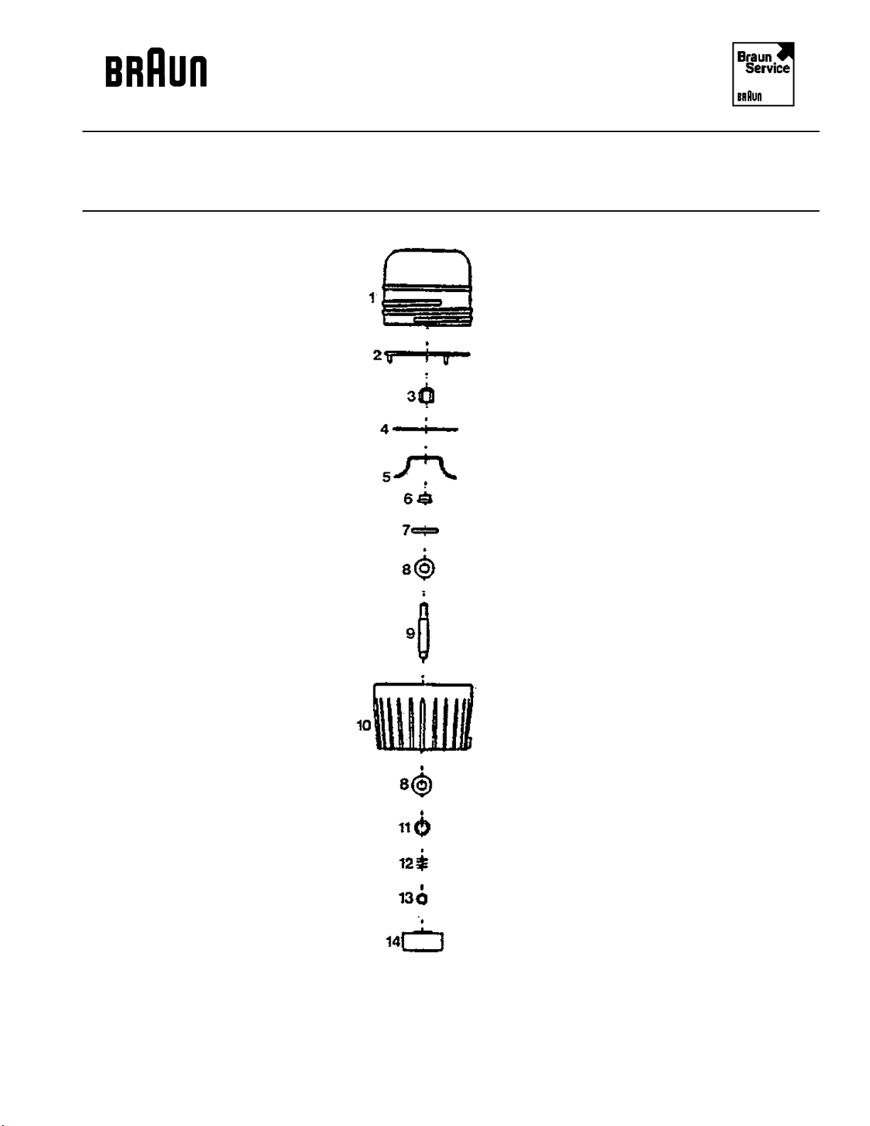
Exploded Drawing
BAG Rev: 7/84 4209
4209 - 2
Page 3

BINC Rev: 7/96 Service Documentation
Service Information
BAG Rev: 12/88 4209
Pos. No. Part Description Part Number
1 Male drive coupling 4207100
2 Upper housing 4207923
3 Attachment cone 4207199
4 Screw 0033120
5 Pivon 4207131
6 Screw 0003302
7 Lower housing 4209875
8 Screw 0001500
9 Stop screw 4207500
10 Protective sleeve 4209003
11 Mains lead 4390264
12 Cable clamp 4206149
12a Cable clamp for pos. 12 4203051
13 Screw 0003170
14 Switch knob 4216193
15 Terminal block 0717253
16 Screw 0002706
17 Resistor 0612717
18 Capacitor 0622099
19 Glow lamp NLA
20 Glow lamp holder 4230051
21 Switch 4230005
22 Bottom plate cpl. NLA
23 Foot 4243054
24 Screw 0034115
25 Fan wheel 4230002
26 Suspension of the motor 4207534
27 Rubber buffer 4230006
28a Washer 0108111
28 Screw 0003135
29 Screw 0028101
30 Washer 0102102
31 Motor 4230550
32 Screw 0030112
33 Upper end shield 4250806
34 Rotor 4230846
35 Washer 4250016
36 Washer 4250017
37 Stator 4230847
38 Air baffle 4250070
39 Thermo-switch NLA
40 Tension spring for pos. 39 NLA
4209 - 3
Page 4

BINC Rev: 7/96 Service Documentation
Spare Parts List
BAG Rev: 12/88 4209
Pos. No. Part Description Part Number
41 Carbon brush 4250048
42 Fixing clamp 4250047
43 Lower end shield 4243817
44 Centering rubber 4250045
45 Capacitor NLA
46 Ferrite-tube 4243078
- Insulating tube NLA
- Plug junction 0710127
- Double plug junction NLA
- Wiring (w/ 1 slip on terminal) NLA
- Wiring (w/ 2 slip on terminals) NLA
- Type plate NLA
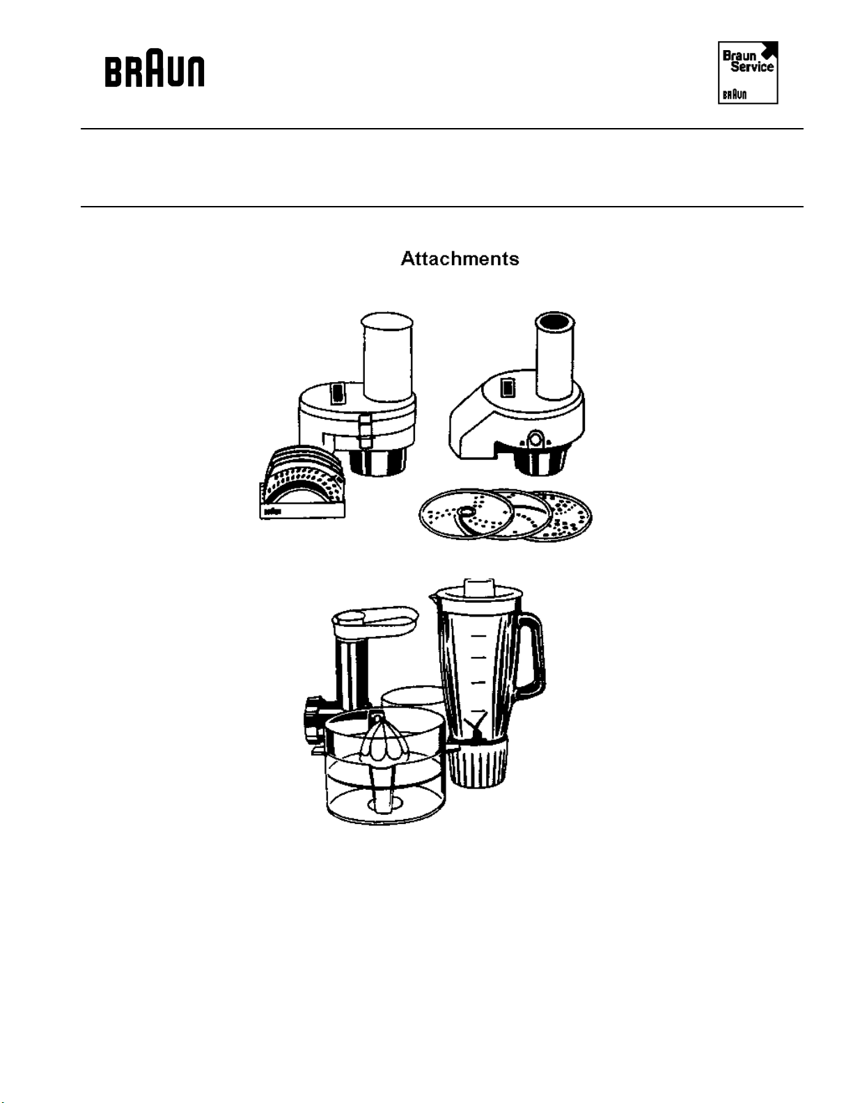
Accessories
Large mixing bowl 4203014
Small mixing bowl 4207055
Dough hook 4207814
Whisk 4207048
Whisk for whipped cream 4207620
Circlip for whisk/hook 4207530
Spatula 4203118
Dust cover 4203200
For additional attachment parts see page 16
4209 - 4
Page 5
BINC Rev: 7/96 Service Documentation
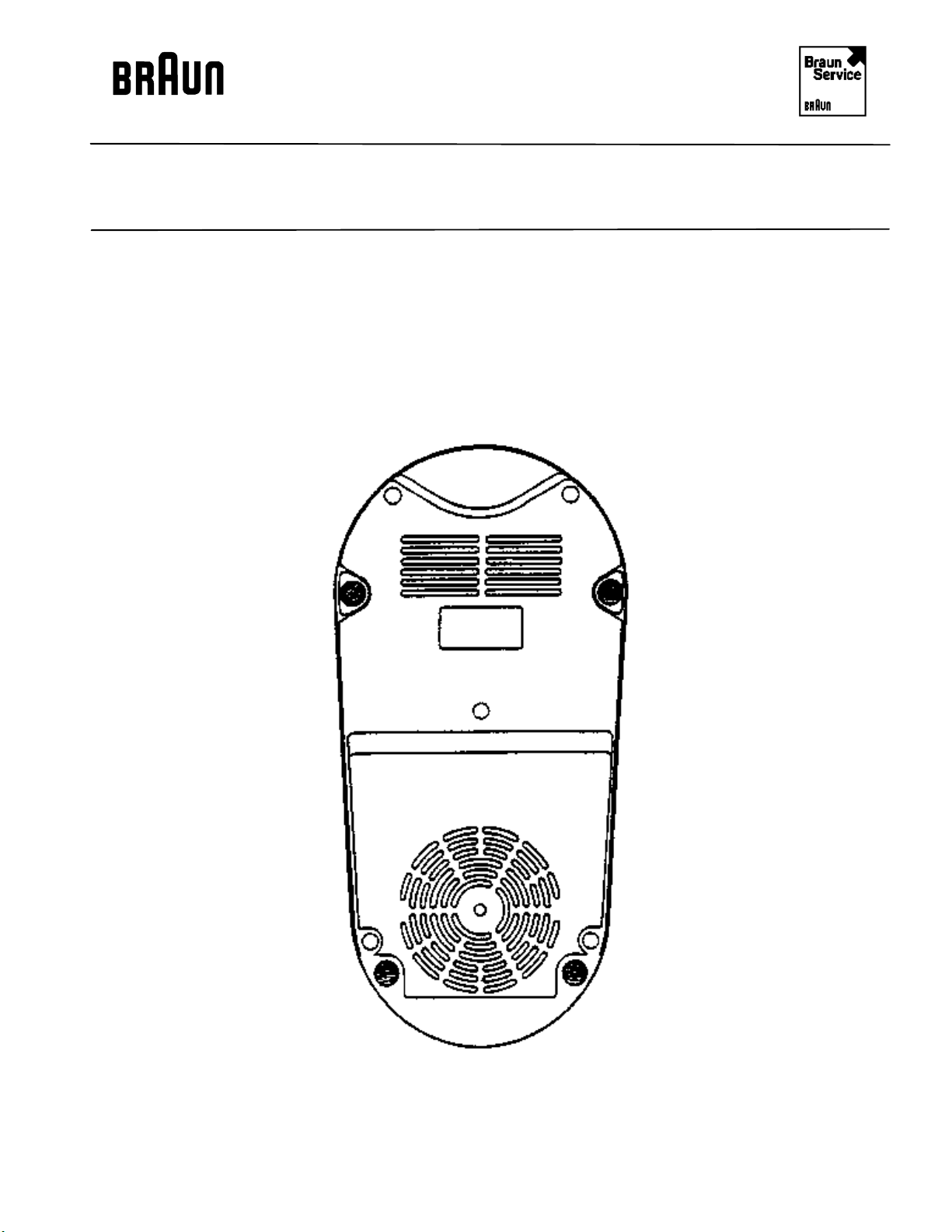
Reference Drawing
BAG Rev: 7/84 4209
Bottom of the product
4209 - 5
Page 6

BINC Rev: 7/96 Service Documentation
Service Information
BAG Rev: 12/88 4209
Technical Data
Voltage/Frequency: 110 V/120 V 40-60 Hz
No-load power Position 1: appr. 125 W + 10 %
Position 2: appr. 130 W + 10 %
Position 3/L: appr. 205 W + 10 %
No load speed Position 1: appr. 10700 min
Position 2: appr. 12500 min
Position 3/L: appr. 16000 min
-1
-1
-1
Overheating protection: Thermo-switch/Fuse
Length of mains lead: appr. 1.30 m
Operating time: continuous operation at 400W
4209 - 6
Page 7

BINC Rev: 7/96 Service Documentation
Service Information
BAG Rev: 7/84 4209
1. Removal of motor (31)
Disconnect appliance mains plug from the socket. Loosen the holding screws from the bottom
cover plate (22) and remove plate. Then withdraw the male-drive coupling (1) with the aid of
an angle-shaped screw-driver.
Draw off switch knob (14) and unscrew switch securing screws (8, 9). Proceed by
disconnecting the motor wiring on the terminal block (15). Subsequently loosen the 4 screws
(28) with a long screw-driver and take the motor together out of the housing.
2. Reassembly
The reassembly is carried out in the reverse order, however attention should be paid to the
rubber buffer (27).
The motor shaft must be supported at the bottom end, when the new male drive coupling (1) is
mounted onto the shaft. Pay attention to the wiring diagram.
3. Replacement of the thermo-switch (39)
Remove motor (31) as described in paragraph 1.
Withdraw the air baffle (38) and loosen spring (40). Continue by disconnecting the plug
connection on switch (21) and also connection on the terminal block (15) and install new
thermo-switch.
4. Dismantling of motor (31)
With the aid of a screwdriver, push off the fan wheel (25).
Before starting to dismantle the motor, mark the latter in the longitudinal direction, so that all
parts are again placed correctly left to right during the assembly. Use a 8 mm box spanner for
removing screws (32). Before the motor is taken apart, first remove the carbon brushes (41).
Prior to removing the brushes, loosen the fixing clips (42) at the sides and withdraw carefully.
5. Carry out a functional test
4209 - 7
Page 8
BINC Rev: 7/96 Service Documentation
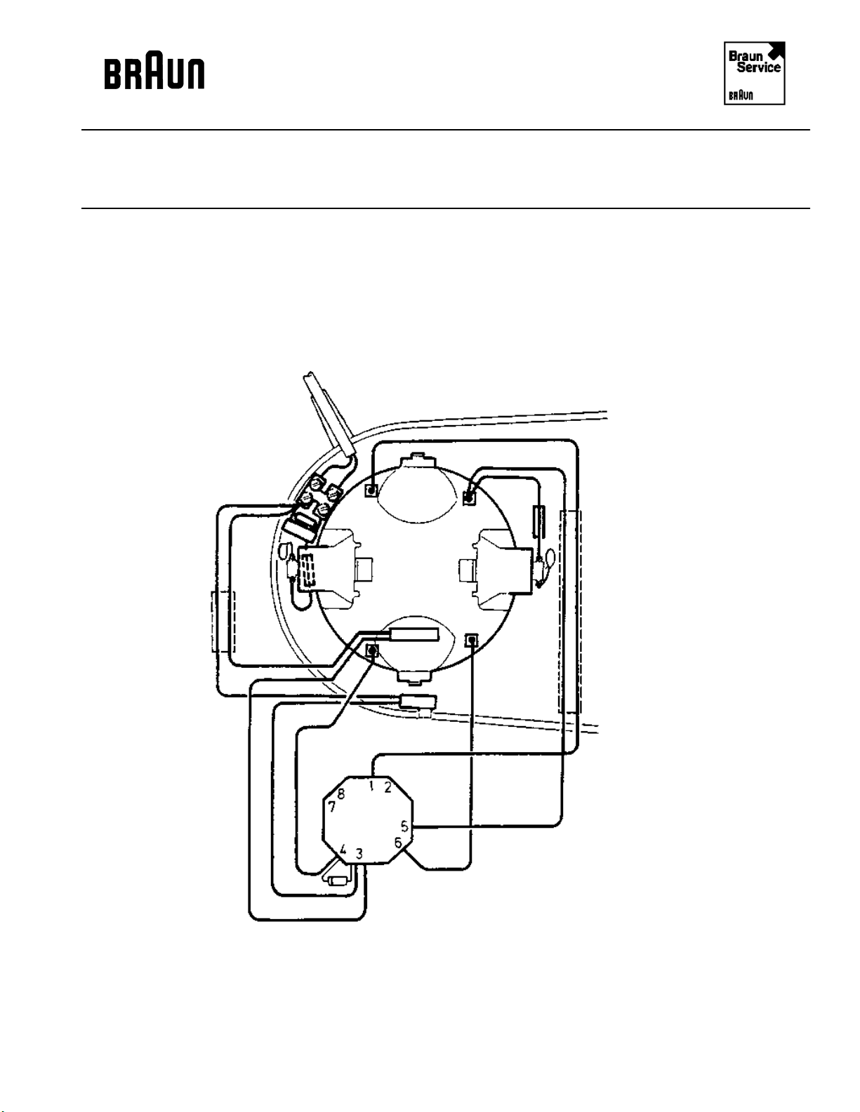
Reference Drawing
BAG Rev: 7/84 4209
Wiring with thermo-switch
4209 - 8
Page 9
BINC Rev: 7/96 Service Documentation
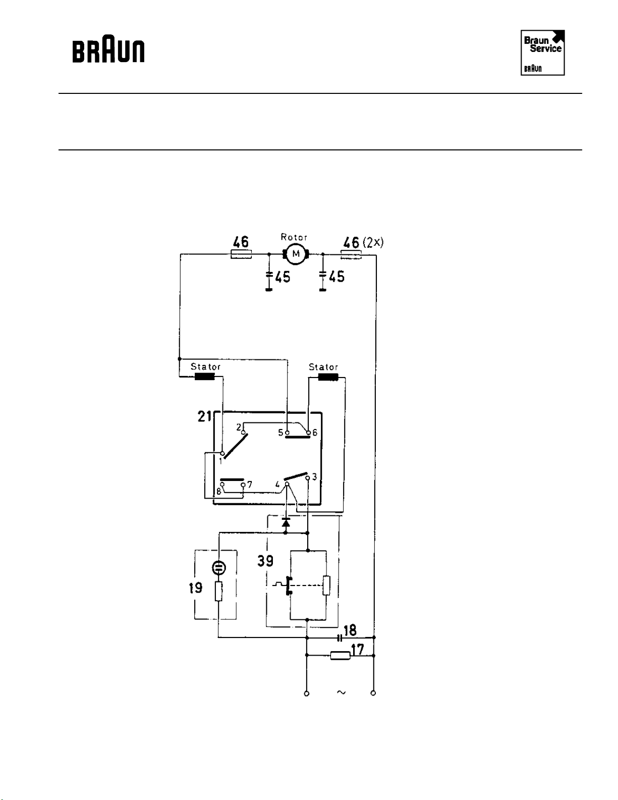
Reference Drawing
BAG Rev: 7/84 4209
Wiring diagram
4209 - 9
Page 10

BINC Rev: 7/96 Service Documentation
Reference Drawing
BAG Rev: 10/88 4209
Wiring diagram
4209 - 10
Page 11

BINC Rev: 7/96 Service Documentation
Service Information
BAG Rev: 11/85 4209
Products which are considered to be too loud or are returned for this defect.
When judging the operating noise, the mixing arm of KM 32/B or the mixer attachment of the MX
32/B should be engaged. If the operating noise is still considered to be too loud, the following
measures should be taken:
1. The motor should not have any off-center condition that means, the outside diameter of
the male drive coupling (Pos. 1 must coincide with the inside diameter of the raised
attachment cone shoulder (observe an even gap!). If necessary this has to be newly
adjusted.
2. All screws of the motor-suspension (Pos. 26 respectively 37) must be tightly fastened. If
necessary. this has to be corrected.
3. The motor suspension (Pos. 26 respectively 37), must be checked for areas of breakage or
other defects if necessary the parts must be exchanged.
4. Remove the lower centering rubber parts of the motor (Pos. 44 resp. 58 and attach, if
necessary, the new and Changed base plate (see instructions below).
Instructions for Braun kitchen machine KM 32/B (4209) and Braun multimix MX 32/B (4142)
From production week 45,1985 on, the lower four rubber buffers (Pos. 27 resp. 38) of the motor
suspension (plastic-type), will be eliminated without a replacement. The motor suspension will be
changed accordingly. In previously produced products, the rubber buffers should continue to be
used.
At the same time, also the previously used centering rubber parts (Pos. 44 resp. 58) will be
eliminated without a replacement. Also in this case, the base plate has been changed accordingly.
That means the holes to accept the centering rubber parts in the base plate, have been eliminated.
For replacement of these parts, ribs have been molded in the same spot. It is not possible, to attach
the new base plate, if the motor still has any centering rubber parts.
The new base plate can be used without problem for previously produced products, it the centering rubber parts have been removed.
Only when these points have been considered, the machine will correspond with the noise allowed
by the factory.
4209 - 11
Page 12
BINC Rev: 7/96 Service Documentation
Exploded Drawing
BAG Rev: 7/84 4209
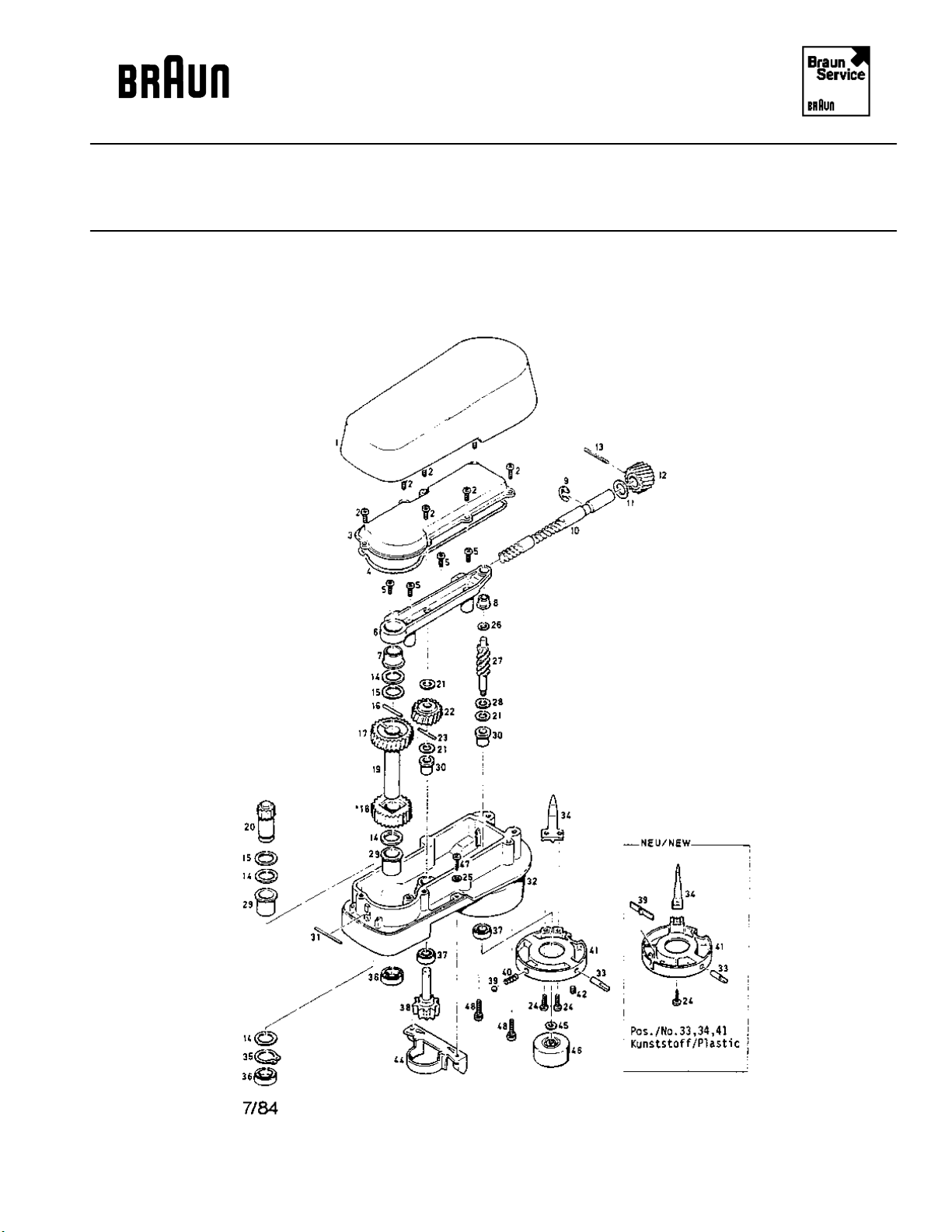
Mixing arm for Kitchen Machine
4209 - 12
Page 13

BINC Rev: 7/96 Service Documentation
Spare Parts List
BAG Rev: 2/94 4209
Pos. No. Part Description Part Number
1 Mixing arm cover 4207033
2 Screw 0030008
3 Gear cover 4207020
4 Rubber seal 4207044
5 Screw 0030008
6 Bearing bracket 4207822
7 Flanged bearing 4207107
8 Flanged bearing 4207005
9 Circlip 0109301
10 Main worm shaft 4207394
11 Fiber washer 4207019
12 Worm gear 4207478
13 Spring pin 0127201
14 Fiber washer 4207015
15 Washer 4207014
16 Grooved pin 0125102
17/18 Gear wheel-set 4207623
19 Shaft 4207821
20 Pinion 4207820
21 Fiber washer 4207007
22 Worm gear 4207010
23 Pin 4207384
24 Screw 0003135
24 Screw, self tapping * 0038022
25 Washer 0103001
26 Fiber washer 4207008
27 Driving worm 4207006
28 Washer 4207034
29 Flanged bearing 4207004
30 Flanged bearing 4207002
31 Retaining rod 4207112
32 Mixing arm housing 4207819
33 Coupling pin (Metal) 4207030
33 Coupling pin (Plastic) * 4207533
34 Locking lever (Metal) 4207028
34 Locking lever (Plastic)* 4207528
35 Circlip 0112001
36 Radial oil seal ring 4207351
37 Radial oil seal ring 0104003
38 Bowl drive with shaft 4207035
39 Ball 0162002
4209 - 13
Page 14

BINC Rev: 7/96 Service Documentation
Spare Parts List
BAG Rev: 2/94 4209
Pos. No. Part Description Part Number
39 Leaf spring * 4207529
40 Spring 4207180
41 Locking ring (metal) 4207027
41 Locking ring (plastic) * 4207527
42 Grub screw 0015101
44 Guide bracket 4207032
45 Distance washer 4213042
46 Coupling 4203055
47 Screw 0031077
48 Screw 0003126
No. 17 and 18 are replaced together.
* Parts that are to be replaced together. When rebuild from metal to plastic version all
parts with * should be used together.
4209 - 14
Page 15

BINC Rev: 7/96 Service Documentation
Reference Drawing
BAG Rev: 11/85 4209
4209 - 15
Page 16
BINC Rev: 7/96 Service Documentation
Service Information
BAG Rev: 8/85 4209
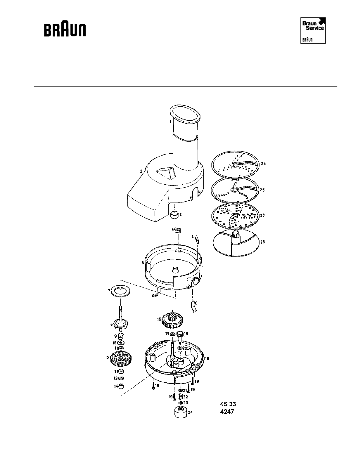
Shredder KS 33 4247
Meat Mincer KGZ 2 4610
Citrus Juicer KMZ 3 4612
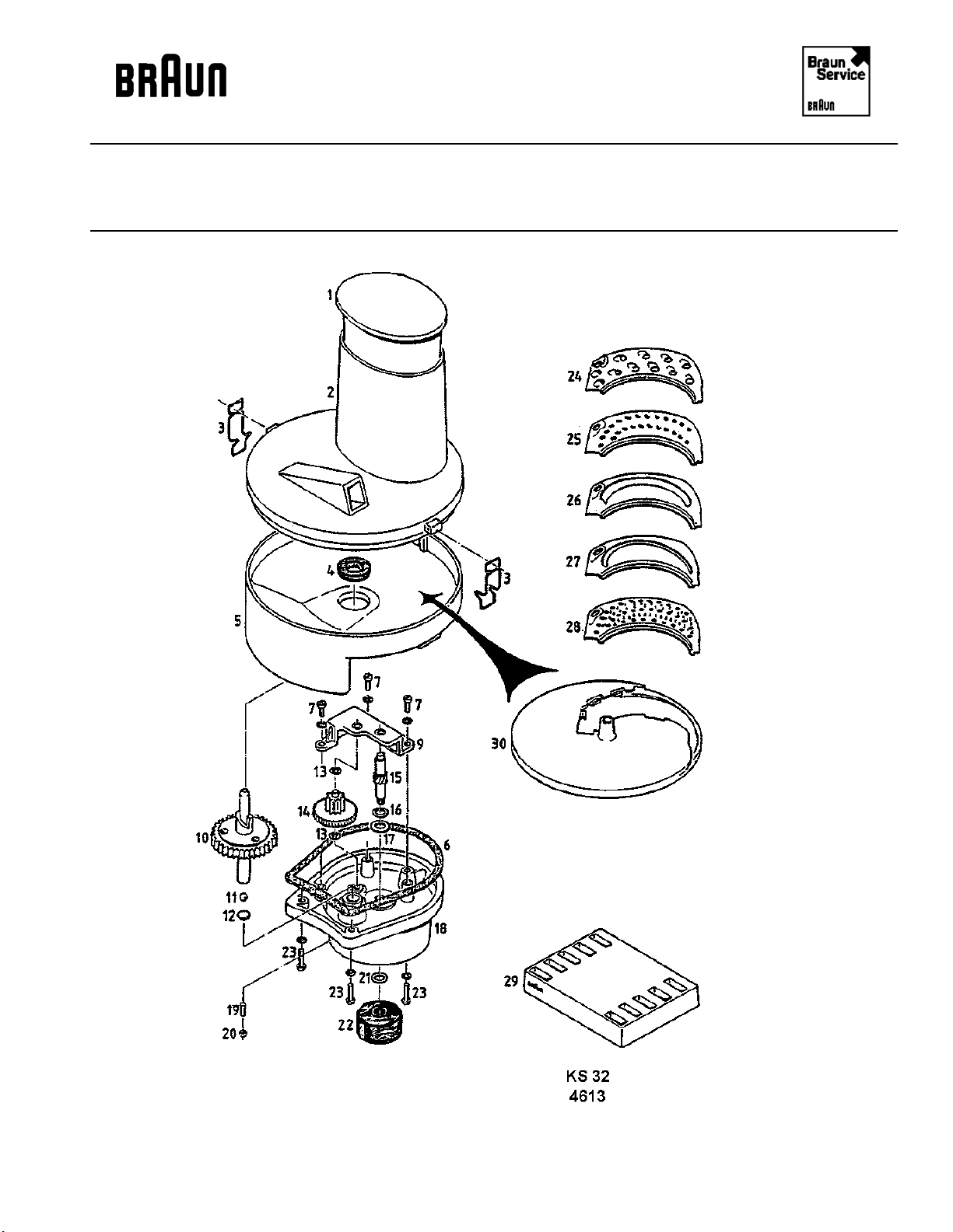
Shredder KS 32 4613
Liquidizer KX 32 4614
Coffee Grinder MXK 4615
4209 - 16
Page 17
BINC Rev: 7/96 Service Documentation
Exploded Drawing
BAG Rev: 8/85 4247
4209 - 17
Page 18

BINC Rev: 7/96 Service Documentation
Spare Parts List
BAG Rev: 6/91 4247
Pos. No. Part Description Part Number
1 Pusher 4207492
2 Lid with no. 3 4247851
3 Cap 4247022
4 Guide block 4247035
5 Upper housing cpl. 4247852
6 Flat spring 4247028
7 Felt washer 4242126
8 Driving shaft coupling 4247853
9 Spring 4247007
10 Washer 4247026
11 Thrust bearing 4247037
12 Gear wheel 4247015
13 Washer 4247025
14 Swivel bearing 4247024
15 Intermediate gear wheel 4247014
16 Pinion 4247016
17 Fibre washer 4247017
18 Lower housing 4247625
19 Screw 0031052
20 Fibre washer 4250082
21 Bronze washer 4213041
22 Spring 4203135
23 Washer 4213042
24 Coupling 4203055
25 Working disc I 4247047
26 Working disc II 4247048
27 Grater disc for potatoes 4247039
28 Carrier disc 4247858
- Adapter for KMZ 3 4247038
4209 - 18
Page 19

BINC Rev: 7/96 Service Documentation
Exploded Drawing
BAG Rev: 1/82 4610
4209 - 19
Page 20

BINC Rev: 7/96 Service Documentation
Spare Parts List
BAG Rev: 12/83 4610
Pos. No. Part Description Part Number
Gear Head for Meat Mincer
1 Cover 4241020
2 Cheese-head screw 0003101
3 Split lock washer 0101001
4 Upper gear housing cover 4240803
5 Plain seal 4240012
6 Steel washer 4240021
7 Worm drive shaft 4240003
8 Fiber washer 4213040
9 Gear wheel 4240008
10 Fiber washer 4240004
11 Intermediate gear 4240022
12 Plain seat 4240025
13 Gear shaft 4240807
14 Split lock washer NLA
15 Cheese head screw NLA
16 Winged screw 4241003
17 Retainer ring 0109003
18 Bronze washer 4241014
19 Fiber washer 4241015
20 Straight pin 0120101
21 Shaft 4240009
22 Seal-ring 0104001
23 Lower housing 4240801
24 Seal-ring 0712001
25 Washer 4213042
26 Coupling 4203055
4209 - 20
Page 21

BINC Rev: 7/96 Service Documentation
Spare Parts List
BAG Rev: 2/95 4610
Pos. No. Part Description Part Number
Meat Mincer attachment
1 Tamper 4242 040
2 Meat tray 4241004
3 Housing 4240811
4 Worm screw 4240045
5 Spring 4242148
5 Spring 4242148
6 Cross shaped blade ** 4242133
6 Cross shaped blade 4240048
7 Perforated disc, 4.5 dia. 4 195090
7 Perforated disc, 3.0 dia. 4 195091
7 Perforated disc, 8.0 dia. 4195092
8 Locking ring 4240050
** Two sided applicable
4209 - 21
Page 22

BINC Rev: 7/96 Service Documentation
Exploded Drawing
BAG Rev: 1/82 4612
4209 - 22
Page 23

BINC Rev: 7/96 Service Documentation
Spare Parts List
BAG Rev: 10/86 4612
Pos. No. Part Description Part Number
1 Reamer cone 4207391
2 Strainer 4253285
3 Juice container 4253284
- Adapter for KS 33 4247038
4209 - 23
Page 24
BINC Rev: 7/96 Service Documentation
Exploded Drawing
BAG Rev: 1/82 4613
4209 - 24
Page 25

BINC Rev: 7/96 Service Documentation
Spare Parts List
BAG Rev: 11/93 4613
Pos. No. Part Description Part Number
1 Tamper (old with lid) 4207809
1 Tamper (new without lid) 4207492
2 Upper housing NLA
3 Retaining clamp 4203270
4 Oil sealing ring 4207093
5 Lower housing NLA
6 Plain seal 4203266
7 Screw 0003101
9 Bearing bracket 4203883
10 Output gear 4203884
11 Ball 0162003
12 Ball thrust plate 4203264
13 Washer 4203257
14 Intermediate gear 4203882
15 Drive shaft 4203254
16 Bronze washer 4213041
17 Fiber washer 4213040
Bearing 4206047
18 Metal housing 4203881
19 Set screw 0016102
20 Nut 0061108
21 Washer 4213042
22 Coupling 4203055
23 Screw 0003170
24 Shredding insert, coarse 4207068
25 Shredding insert, fine NLA
26 Slicing insert, coarse 4207070
27 Slicing insert, fine 4207071
28 Grating insert 4207072
29 Insert stand 4207094
30 Carrier disc 4207807
4209 - 25
Page 26

BINC Rev: 7/96 Service Documentation
Exploded Drawing
BAG Rev: 5/84 4614
4209 - 26
Page 27

BINC Rev: 7/96 Service Documentation
Spare Parts List
BAG Rev: 12/85 4614
Pos. No. Part Description Part Number
1 Funnel plug 4207091
2 Lid 4207090
3 Glass goblet 4216865
4 Rubber gasket 4216209
5 Complete knife (6 - 20) 4216899
6 Cap nut 0064006
7 Washer (Steel) 4291014
8 Upper knife 4207088
9 Lower knife 4207087
10 Cover 4291006
11 Washer (Steel) 4291010
12 Washer (Fibre) 4250082
13 Cutter base plate (Metal) 4291650
14 Washer (Fibre) 4250082
15 Washer (Bronze) 4213041
16 Socket 4216213
17 Spring 4216212
18 Shaft 4216214
19 Washer (Steel) 4213042
20 Coupling 4203055
21 Knife retainer housing 4207835
4209 - 27
Page 28
BINC Rev: 7/96 Service Documentation
Exploded Drawing
BAG Rev: 1/82 4615
MXK 3
4615
4209 - 28
Page 29

BINC Rev: 7/96 Service Documentation
Spare Parts List
BAG Rev: 12/88 4615
Pos. No. Part Description Part Number
1 Glass 4203136
2 Gasket (black) 4203219
3 Cap nut 4203139
4 Middle knife 4203133
4 Middle knife * 4209606
5 Lower knife 4203132
5 Lower knife * 4209605
6 Knife holder 4213039
7 Steel washer 4213038
8 Washer 4213040
9 Knife shaft 4207054
10 Threaded retainer housing NLA
with bottom
11 Bronze washer 4213041
12 Spring 4203135
13 Coupling washer 4213042
14 Coupling 4203055
* Knife Sharpened
4209 - 29
 Loading...