


S19-2000
S86-066
(Cabinet Only)
S19-2000EFX |
|
ASSE 1071 & cUPC Certified |
S19-292 |
|
(Cabinet Only) |
Installation
S19-2000,
S19-2000EFX Series
Thermostatic Mixing Valve with Optional Cabinet
Robinet thermostatique mélangeur
avec cabinet facultatif
Válvula mezcladora termostática con armario opcional
Table of Contents |
|
Supplies Required..................................................... |
2 |
Optional Equipment Installation................................. |
2 |
Dimensions................................................................ |
3 |
Installation Instructions.............................................. |
4 |
Troubleshooting......................................................... |
6 |
Sommaire |
|
Fournitures requises.................................................. |
9 |
Installation de l’équipement optionnel....................... |
9 |
Dimensions.............................................................. |
10 |
Instructions relatives à l’installation......................... |
11 |
Dépannage.............................................................. |
13 |
Tabla de contenidos |
|
Materiales necesarios............................................. |
16 |
Instalaciones de equipos opcionales....................... |
16 |
Dimensiones............................................................ |
17 |
Instrucciones de instalación.................................... |
18 |
Solución de problemas............................................ |
20 |
Inlet Connections: 1/2" NPT |
Raccords d’arrivée : 1/2 po NPT |
Conexiones de entrada: NPT de 1/2 pulg. |
Outlet Connection: 1/2" NPT |
Raccord de sortie : 1/2 po NPT |
Conexión de salida: NPT de 1/2 pulg. |
Temperature Range: 65° – 90° F |
Plage de température : 65 – 90 °F |
Rango de temperaturas: 65 – 90 °F |
Maximum Pressure: 125 PSI |
Pression maximum : 125 lb/po2 |
Presión máxima: 125 PSI |
Inlet Temperature Hot: 120° – 180° F |
Température d’arrivée, eau chaude : 120 – 180 °F |
Temperatura de entrada, caliente: 120 – 180 °F |
Inlet Temperature Cold: 33° – 80° F |
Température d’arrivée, eau froide : 33 – 80 °F |
Temperatura de entrada, fría: 33 – 80 °F |
Minimum Temperature Differential |
Différence de température minimum |
Diferencial de temperatura mínima |
(from valve set point): 20° F |
(à partir de valeur de consigne de robinet) : 20 °F |
(desde el punto de ajuste de la válvula): 20 °F |
Flow at 30 psi: 7.3 gpm |
Débit à 30 psi : 7.3 gpm |
Flujo a 2,1 bar: 7.3 gpm |
Minimum Cold Water Bypass at 30 psid: 5.6 gpm |
Dérivation d’eau froide minimum à 30 psid : 5.6 gpm |
Derivación mínima de agua fría a 2,1 bar: 5.6 gpm |
Minimum Flow: 1.5 gpm |
Débit minimum : 1.5 gpm |
Flujo mínimo: 1.5 gpm |
Maximum Flow with Cold Water Shut-Off: 0.5 gpm |
Débit maximum avec arrêt d’eau froide : 0.5 gpm |
Flujo máximo con retención de agua fría: 0.5 gpm |
215-1291 Rev. R; ECN 14-09-026 |
P.O. Box 309, Menomonee Falls, WI 53052-0309 |
|
© 2014 Bradley |
||
Phone: 1.800.BRADLEY Fax: 262.253.4161 |
||
Page 1 of 22 7/23/2014 |
bradleycorp.com |
S19-2000, S19-2000EFX |
Installation |
Installation |
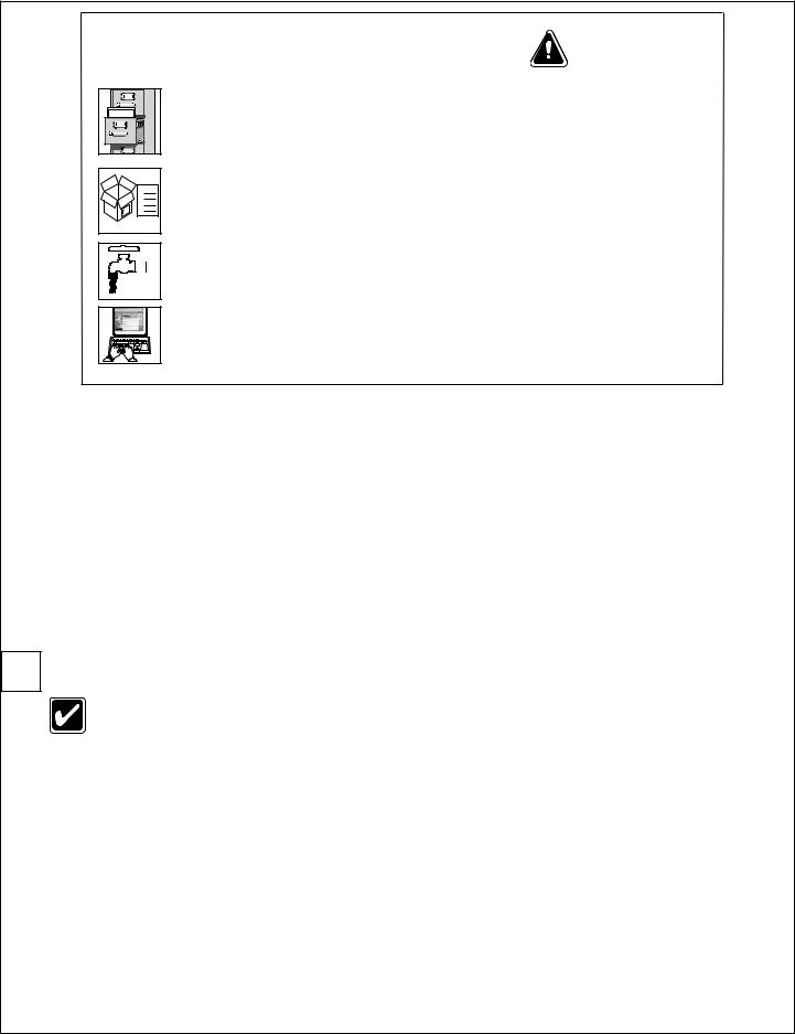
Packing List
|
• |
|
• |
THIS |
• |
UP |
• |
SIDE |
|
 IMPORTANT!
Read this entire installation manual to ensure proper installation. When finished with the installation, file this manual with the owner or maintenance department. Compliance and conformity to local codes and ordinances is the responsibility of the installer.
Separate parts from packaging and make sure all parts are accounted for before discarding packaging material. If any parts are missing, do not begin installation until you obtain the missing parts.
Valve shall be accessible for testing, adjusting and maintenance in the installed position.
Make sure that all water supply lines have been flushed and then completely turned off before beginning installation. Debris in supply lines can cause valves to malfunction.
Product warranties may be found under “Products” on our web site at bradleycorp.com.
Supplies recommended for installation
•Lockable shut-off on the outlet if tempered water is supplied to one or more emergency fixtures
•Lockable shut-off on the inlets/supplies
•(6) 1/4" wall anchors and fasteners for surface-mounted cabinet
•(4) 1/4" fasteners (and wall anchors, if necessary) for recess-mounted cabinet
•Unions on all connections to facilitate removal of valve
Tools required for temperature adjustment
•5/64" Allen wrench
•Blade screwdriver
1 Install Optional Cabinet (If not installing cabinet, skip to Step 2)
If installing S19-2000EFX into Dropdown Eyewash Cabinet S19-292, please see mounting instructions supplied with cabinet.
Recessed Cabinet:
1.Rough-in wall opening 11-1/2" W x 13" H.
2.Insert the cabinet and secure to wall with four 1/4" fasteners properly anchored (supplied by installer.)
3.Install two anchors and screws through the valve bracket in back of the cabinet into a secure brace (supplied by installer) or into wall. This will support the valve.
4.Install the valve nipples and one-half of the union ball valve using pipe sealant or teflon tape. Install the other half of the union ball valve onto inlet and outlet pipe.
5.Insert the valve into the bracket in the cabinet (right side goes in first). Continue with the valve installation procedure.
6.Position the wall flange tight to the wall and caulk in place.
Surface-Mounted Cabinet:
1.Measure and mark the cabinet mounting hole locations at the dimensions shown on next page. Install six 3/8" wall anchors (supplied by installer).
2.Position the cabinet onto the wall and secure into place with six 3/8" wall fasteners (supplied by installer).
3.Install the valve nipples and one-half of the union ball valve using pipe sealant or teflon tape. Then install the other half of the union ball valve onto the inlet and outlet piping.
4.Insert the valve into the bracket in the cabinet (right side of the valve goes in first). Continue with the valve installation procedure.
2 |
7/23/2014 |
Bradley • 215-1291 Rev. R; ECN 14-09-026 |

Installation |
|
|
|
|
|
|
|
S19-2000, S19-2000EFX |
||
Optional Recessed Cabinet |
|
|
|
Side View |
|
(mm) |
||||
Front View |
|
|
|
|
|
|
|
|||
|
|
9¾" |
|
Wall |
|
|
½" NPT |
2" |
|
|
|
|
(248) |
|
|
|
Outlet |
|
|
||
5³⁄" |
|
Door |
|
Flange |
|
|
|
(51) |
|
|
|
|
|
|
|
|
|
2" |
|
|
|
(137) |
|
|
|
|
|
|
2½" |
|
|
|
|
|
|
|
|
|
(51) |
|
|||
|
|
|
|
|
|
|
|
|||
|
|
|
|
|
|
|
(64) |
|
|
|
|
|
|
|
|
|
|
|
|
|
2½" |
|
|
|
|
|
|
|
|
|
|
(64) |
11¼" |
|
|
|
14½" |
|
|
|
|
|
|
(286) |
|
|
|
|
|
|
|
|
12½" |
|
|
|
|
(368) |
|
|
|
|
|
||
Door |
|
|
|
|
|
|
|
|
||
|
|
|
|
|
|
|
|
|
(318) |
|
|
|
|
|
|
|
|
|
|
|
|
|
|
|
|
|
|
|
7-1/2" |
|
|
|
|
|
|
|
|
|
|
(190) |
|
|
|
|
|
|
|
|
Bottom View |
|
|
|
|
|
3" |
5" |
|
|
|
|
|
|
|
|
|
(76) |
(127) |
11" |
|
|
|
|
|
6½" |
|
2¼" |
|
|
|
|
|
|
|
|
|||
|
|
(279) |
|
|
|
|
|
(165) |
|
(57) |
13" |
|
Box |
|
|
|
|
⁄" Dia. Holes |
|
|
½" NPT |
(330) |
|
|
|
|
|
|
(4) each side, |
|
|
Inlets |
|
|
|
|
|
|
|
(8) Total |
|
|
|
Optional Surface-Mounted Cabinet |
11" |
|
|
|
|
|
||||
(279) |
|
|
|
|
|
|||||
|
|
|
|
|
|
|||||
|
|
9¾" |
|
|
|
|
|
|
|
|
|
|
(248) |
|
|
½" NPT |
|
2" |
|
|
|
5½" |
|
Door |
|
|
|
(51) |
|
|
|
|
(140) |
|
|
|
|
Outlet |
|
|
|
|
|
|
|
|
|
|
|
|
|
|
|
|
|
|
|
|
|
|
|
2½" |
|
|
|
|
|
|
|
|
|
|
(64) |
|
|
|
11¼" |
|
|
|
|
|
|
12½" |
|
|
|
(286) |
|
|
|
|
|
|
|
|
|
|
|
|
|
|
|
|
(318) |
|
|
|
|
Door |
|
|
|
|
|
|
|
|
|
|
|
|
|
|
|
|
|
|
|
|
|
|
|
|
|
|
|
|
|
|
|
Mounting Hole |
|
|
|
|
|
|
|
|
|
|
Locations |
|
|
|
|
|
|
|
|
⁄" (8) Dia. Holes |
||
3" |
|
5" |
|
|
½" NPT |
6½" |
2¼" |
(6) Total |
||
|
|
|
(165) |
(57) |
|
|
|
|||
(76) |
|
(127) |
11" |
|
Inlets |
|
|
|
|
|
|
|
|
|
|
|
|
|
|||
|
|
|
(279) |
|
|
|
|
|
|
|
|
|
|
Box |
|
|
|
|
|
|
|
|
|
|
|
|
|
|
8½" |
|
|
|
|
|
|
|
|
|
|
(216) |
|
|
|
|
|
|
|
|
|
|
3¼" |
|
|
|
|
|
|
|
|
|
|
(83) |
|
|
|
|
|
|
|
|
|
|
2" |
¾" |
|
|
|
|
|
|
|
|
|
(19) |
|
5½" |
|
|
|
|
|
|
11" |
|
(51) |
|
||
|
|
|
|
|
(279) |
|
2" |
|
7" |
(140) |
|
|
|
|
|
|
|
(51) |
|
(178) |
|
Bradley • 215-1291 Rev. R; ECN 14-09-026 |
|
|
7/23/2014 |
|
|
3 |
||||
S19-2000, S19-2000EFX |
Installation |
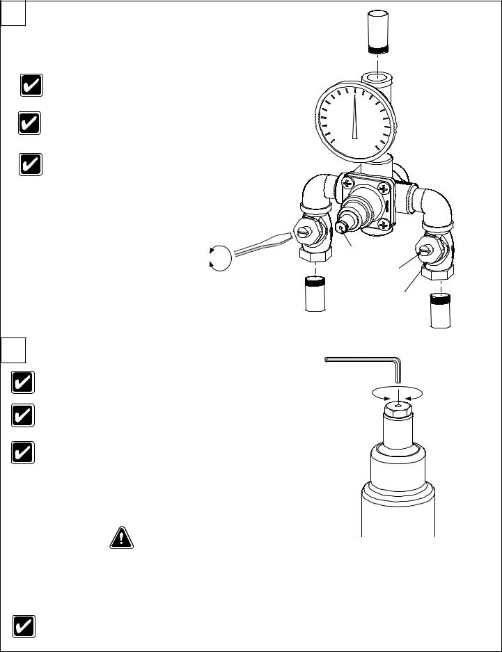
2 Connect Supply Lines and Fixture
Tempered Water
(to Fixture)
Check for leaks by pressurizing unit SLOWLY.
Check the temperature when approx. 3-5 gpm water flow is reached (equivalent to one eye wash or face wash) and adjust if necessary.
When the check stops are in the fully open (operating) position, the stem will extend approximately 1/2" (13mm) from the stem nut.
Open |
|
Hole In Cap |
|
|
|
Close |
|
Stem |
|
|
|
|
HOT |
Stem Nut |
|
|
COLD
S19-2000 Shown
3 Adjust Temperature with Water Running
Check the temperature when approximately 3 – 5 gpm water flow is reached (equivalent to one eye wash).
No single emergency fixture supplied by this device shall have a minimum flow rate less then 1.5 gpm.
This device must be checked for final temperature and adjusted as necessary. The standard preset factory temperature setting is 85°F (29°C) [the range of the valve is 65°F–90°F (18°C–32°C)]. Insert Allen Wrench through the hole in the cap and into the set screw
to adjust. Consult proper medical and/or safety authorities for the optimum temperature recommended for your particular application.
4 |
Test Unit |
DO NOT SKIP THIS STEP!!! |
|
5/64" Allen Wrench
H
C
Shut the hot water supply off by closing hot water inlet valve or supply check valve. While the hot water supply is turned off, check to make sure the cold water continues to flow. If the cold water is flowing properly, reopen the hot water supply.
Shut the cold water supply off by closing the cold water inlet valve or supply check valve. While the cold water supply is off, check to make sure that the hot water flow has shut down to less then 0.5 gpm. If hot water is shut down, fully reopen cold water supply.
Test the system weekly (turn on the water supply and check for constant control of the desired set temperature).
4 |
7/23/2014 |
Bradley • 215-1291 Rev. R; ECN 14-09-026 |
Installation |
S19-2000, S19-2000EFX |
|
|
|
|
5 |
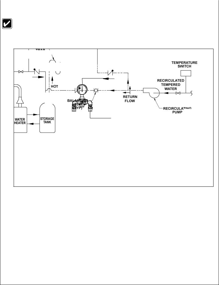
Optional Water Recirculation Setup |
|
Recirculating the water in the system provides constant regulation of the water temperature. Flush the supply lines thoroughly after completing installation. Close off all fixtures and label them as not available for use during the recirculating process.
Check Valve
(Typ)
COLD |
Tempered Water Flow |
Cold
Water
Heat Trap
28" Drop
Temperature Switch
|
Recirculated |
HOT |
Tempered |
Water |
Return Flow
Balancing Valve (Typ)
Recirculating Pump
Water |
Storage |
Heater |
Tank |
1.Turn off the recirculating pump and turn on the water supply at emergency fixture (a water flow rate of 3 – 5 gpm is required).
2.Let the water run through the system until a consistent temperature is obtained. If you do not obtain the required temperature, refer to step #3 on previous page for temperature readjustment.
3.As soon as the water reaches the proper temperature, turn on the recirculating pump (make certain the proper system temperature has been achieved before proceeding).
4.Check the water temperature at the return pump. If the temperature exceeds the appropriate level by 2°F, adjust the temperature high-limit switch (this will turn off the pump). Wait until the return water temperature is 5°F below the appropriate level and adjust the low-limit switch (this will turn the pump back on).
5.Open the balancing valve completely.
6.Turn off all fixtures and make sure there is no water running through the system (the cold inlet pipe should feel warm to the touch).
7.Let the system run for 30 minutes or longer without water. If, after thirty minutes, the water temperature increases, you may readjust the temperature by slowly closing the balancing valve until the appropriate temperature is reached.
Bradley • 215-1291 Rev. R; ECN 14-09-026 |
7/23/2014 |
5 |
S19-2000, S19-2000EFX |
Installation |
|
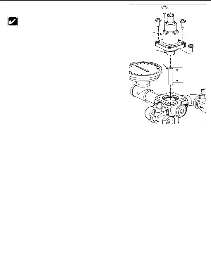
Troubleshooting Thermostatic Mixing Valve |
|
|
Before attempting to troubleshoot the valve or |
|
|
disassemble the components, check for the following: |
|
|
• Stop/check valves are fully open (the slotted stem |
Top Cap & |
|
extends approximately 1/2" from the stem nut) and |
||
Thermostat |
||
that all inlet and outlet shut-off valves are open. |
||
|
||
• Hot and cold inlet pipes are connected properly, |
|
|
and that there are no cross-connections or leaking |
|
|
stop/check valves. |
Thermostat |
|
• Water heater output is at least 20° F above the set |
Bellows |
|
|
||
temperature. |
5/16" Push |
|
|
||
Be sure to close the appropriate shut-off valves prior |
Rod |
|
to disassembly of the valve and reopen the valves |
|
|
after inspection and repair is complete. |
Push Rod length |
|
|
should extend |
|
|
15/16" – 1-3/16" |
|
|
into Bellows |
Problem |
Cause |
Solution |
External leaks in the |
Either the NPT joints or the o-rings have been |
Replace the NPT joints and/or o-rings where necessary. For |
system |
damaged. |
replacement of o-rings, contact your Bradley representative and ask |
|
|
for O-Ring Seal Kit (S65-170). |
|
|
|
No hot water flow (cold |
The thermostat has failed and, subsequently, the |
Inspect Thermostat: |
water flow only) |
safety shut-off has engaged. |
1. Remove the top cap and thermostat. |
|
|
|
Limited water flow |
The inlet shut-off valve may be partially closed |
2. Insert the 5/16" dia. push rod into the thermostat bellows. |
|
or there has been a significant decrease in water |
3. Mark the length the push rod extends into the bellows (at room |
|
pressure. |
|
|
temperature, with 10 lb. of force. the length should be approx. |
|
|
|
|
|
|
15/16" – 1-3/16"). |
|
|
4. If the push rod length is not in the proper range, the thermostat |
|
|
must be replaced (it cannot be repaired). Contact your Bradley |
|
|
representative and ask for Thermostat Kit (S65-171). |
|
|
|
|
Dirt and debris have collected on the check |
Clean Stop and check Valves: |
|
screen or seat, limiting the movement of the stop |
Remove the stop and checks, clean the seat and reassemble the |
|
and checks. |
|
|
valve. Do not remove the seat. The components may be brushed |
|
|
|
|
|
|
with a small wire brush to remove debris. A pair of tweezers works |
|
|
well for pulling debris out from the seat. If the stop and checks need |
|
|
to be replaced, contact your Bradley representative and ask for |
|
|
Check/Stop Kit (S27-102-Rough Brass, or S27-292A-Chrome). |
|
|
|
Temperature fluctuation |
The stop and check sections of the valve do not |
Clean Stop and Check Valves as described above. |
or improper Temperature |
move freely. |
|
|
|
|
|
Thermostat is slowly failing. |
Check Thermostat as described above, or replace. |
|
|
|
|
Inlet supply line to the mixing valve is being |
Enlarge the supply line size, reconfigure the supply line or regulate |
|
shared by other pieces of equipment that are |
the supply usage. |
|
used only periodically, such as laundry appliances |
|
|
or washdown stations. It may reduce the inlet |
|
|
pressure to the mixing valve to less than 3 PSI. |
|
|
The supply line size may not be large enough to |
|
|
supply both the valve and the other appliances. |
|
|
|
|
|
Recirculation is not balanced. |
Review recirculation set up on page 5. |
|
|
|
|
Piston does not move freely and must be cleaned. |
See next page for piston disassembly and cleaning directions. |
|
|
|
6 |
7/23/2014 |
Bradley • 215-1291 Rev. R; ECN 14-09-026 |
Installation |
S19-2000, S19-2000EFX |
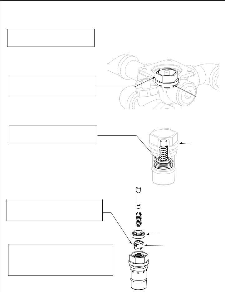
Troubleshooting: Piston Disassembly and Cleaning
A Remove the Top Cap and Thermostat Assembly as shown on Page 6. Set the 5/8" Push Rod aside.
B Using a 15/16" socket wrench, loosen the piston liner from the valve body and lift out with a needle-nose pliers.
Using a 1/2 deep socket wrench, loosen C the piston upper seat from the piston liner
and lift out parts with a needle-nose pliers.
D Dissamble and clean the piston assembly parts with any cleaner suitable for brass and stainless steel. (if necessary, use a 400-grit sandpaper to polish and hone the piston and liner.)
Piston Upper Seat
Piston
Re-assemble the piston assembly. Push the mechanism up and down several times to make sure
E the piston moves smoothly and consistently. If it is not consistent, repeat Procedure D until it moves freely, or replace. Contact your Bradley representative and ask for Piston/Liner Kit (part number S65-172).
Piston Liner
Piston Liner
Bradley • 215-1291 Rev. R; ECN 14-09-026 |
7/23/2014 |
7 |
 Loading...