

Page 1
The Bowflex Sport
Home Gym
Assembly Instructions
®
001-6961 Rev B (06-19-06)
Page 2

Table of Contents
Safety Precautions 1
Get to Know Your Machine 2
Basic Assembly Principles 3
Parts List 3
Hardware List 3
Accessory List 3
Hardware Guide 4
Tools You Will Need 4
Assembly Guide 5
Important Contact Numbers 20
Page 3

Safety Precautions
• Always read and follow the Warning and Safety
labels attached to your Bowflex Sport
gym. Do not remove these labels. If you need
replacement labels, please call a Nautilus
Representative at (800) 605-3369.
• Read the owner’s manual and follow it carefully
before using the machine.
• Parents and others in charge of children should be
aware of their responsibility, because the natural
play instinct and the fondness for experimenting
of children can lead to situations and behavior for
which the training equipment is not intended.
• Never allow children to use the Bowflex Sport®
home gym unsupervised. To do so could result
in injury. If children are allowed to use the
equipment, their mental and physical development
should be taken into account. They should be
controlled and instructed on the correct use of the
equipment.
• This equipment is under no circumstances suitable
as a children’s toy.
• Inspect your machine for any worn or loose
components prior to use. Tighten or replace
any worn or loose components prior to use.
Pay close attention to cables, or belts and
their connections.
• Never use dumbbells or other weight equipment
to incrementally increase the weight resistance.
Use only the Power Rods
Bowflex Sport
®
home gym.
® that came with your
®
home
• This machine is meant for individual consumer use
only, and is not meant for use by institutions.
• Maximum user weight for the Bowflex Sport®
home gym is 300 pounds (136 kg). For your safety,
do not use or allow others to use the Bowflex
Sport® home gym if they weigh in excess of 300
pounds (136 kg).
• Allow a workout area of at least 8’4” x 6’6” (2.6
m x 2 m) of free space for safe operation of the
Bowflex Sport
• Keep your body weight centered on the machine,
seat, or base frame platform while exercising.
• When using the Bowflex
standing leg exercises, always grasp the Lat Bar
on your machine for stability.
• Keep out of the path of the Power Rods
exercising and make certain that observers also
stand clear of the Bowflex
when the Power Rods
• Never move or adjust the seat while sitting on it.
Never stand on the seat.
• When hooking up Power Rods
directly looking over the top of the rods. Stand off
to the side while attaching rods.
• Never attempt to exercise with more resistance
than you are physically able to handle.
• Keep cables and Power Rods
binding strap when not in use.
®
home gym.
Sport® home gym for
® when
Sport® home gym
®
are in use.
® do not stand
® bound with the rod
• Set up and use your Bowflex Sport® home gym
on a hard, level surface.
• Do not wear any loose or dangling clothing or
jewelry while using the Bowflex Sport
gym. Stand clear of all moving components.
• Before beginning any exercise program consult
your physician or health care professional. Only he
or she can determine the exercise program that is
appropriate for your particular age and condition.
If you experience any light-headedness, dizziness,
or shortness of breath while exercising, stop the
exercise and consult your physician.
®
home
• Before exercising, make sure the cable pulley
system is properly secured, properly attached,
and in perfect working condition.
• All exercises in this manual are based on the
calibrated resistance and capacity levels of
the Bowflex Sport
not in this manual are not recommended by
the manufacturer.
• Never attempt to exercise while the seat rail is
in the folded position.
®
home gym. Exercises
1
Page 4
Get to Know Your Machine
CONGRATULATIONS on your commitment to improving your
health and fitness! With the Bowflex Sport ® home gym, you
have everything you need to exceed all of your physical fitness,
strength and health expectations!
The Bowflex Sport ® home gym’s exceptional resistance and
quality is unmatched by any other single piece of home fitness
equipment available. You will not believe the amazing results
your body will get with the Bowflex Sport ® home gym!
Before You Assemble
Select where you are going to locate your
Bowflex Sport® home gym carefully. The
best place for your Bowflex Sport® home
gym is on a hard, level surface. Assemble
your Bowflex Sport® home gym in the
location where you intend to use it, as the
Bowflex Sport® home gym does not go
through doors easily once fully assembled.
Allow a workout area of at least 8’4” x 6’6” (2.6
m x 2.0 m) of free space for safe operation of
the Bowflex Sport
®
home gym.
R
S
T
With all of the fitness choices available today, finding the
best workout equipment for your needs can be confusing.
Everyone at Nautilus would like to congratulate you and thank
you for selecting the Bowflex Sport ® home gym.
The Bowflex Sport ® home gym is the best home fitness
product available, and you’re just about to prove it to yourself.
Home Gym
22
23
12
24
25
15
14
16
30
13
17
21
19
27
U
29
7
18
8
10
5
11
26
9
4
28
1
6
2
3
Page 5

Get To Know Your Machine
Basic Assembly Principles
Here are a few basic tips that will make your assembly of the Bowflex Sport® home gym quick and easy. By using these
principles, you can simplify each process and save yourself extra time and effort.
1. To make the assembly process go faster, gather the pieces you need for each step and thoroughly read the assembly
instructions for that step prior to starting assembly for the step.
2. When tightening a locknut on a bolt, use a combination wrench to grip the locknut and ensure that it is fastened securely.
3. When attaching two pieces, gently lift and look through the bolt holes to help guide the bolt through the holes.
4. As a general rule, and for all bolts and nuts on your Bowflex Sport® home gym, turn bolts or nuts toward the right to tighten
and left to loosen. Or you can remember the mnemonic: “Righty tighty, lefty loosey.”
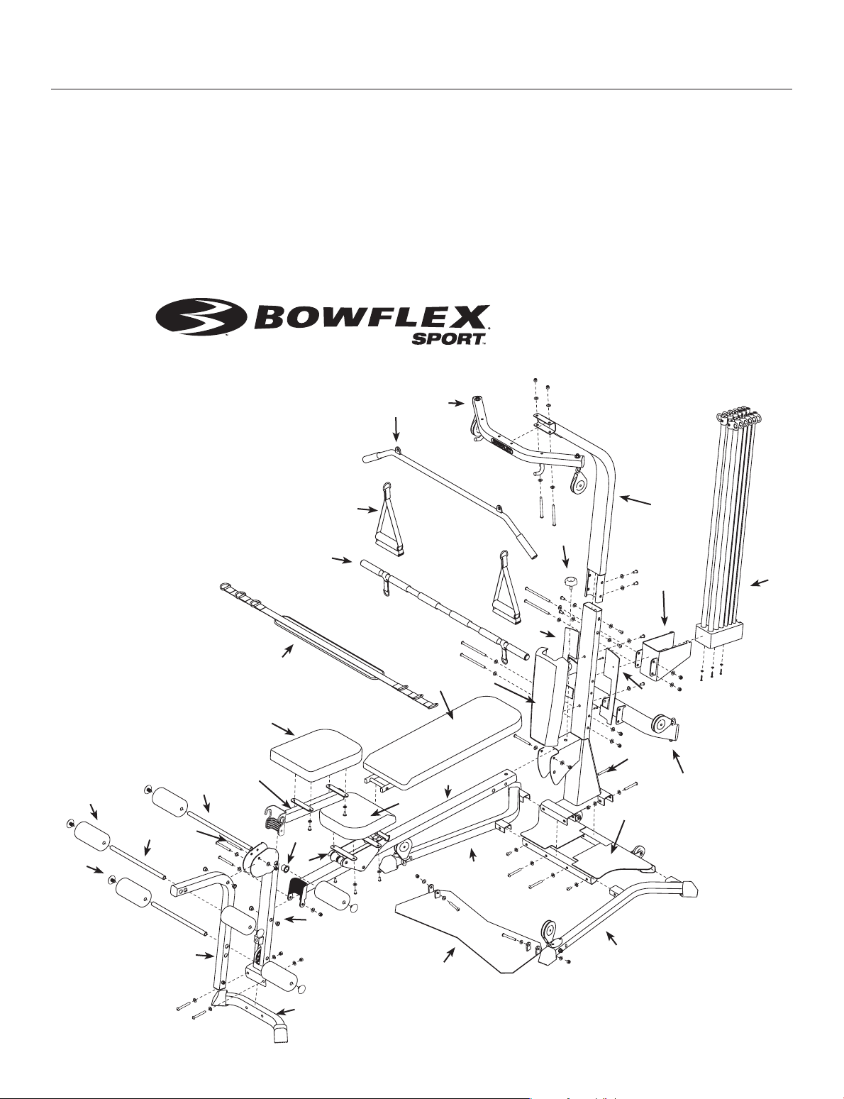
Parts List*
Item No. Qty. Description
1 1 LOWER LAT TOWER
2 1 BASE PLATFORM
3 1 BASE RIGHT LEG
4 1 BASE LEFT LEG
5 1 SQUAT PLATFORM
6 1 CHEST BAR W/ PULLEYS
7 1 SEAT PAD
8 1 SEAT BRACKET
9 1 SEAT RAIL
10 1 REAR LEG
11 1 REAR LEG CROSS TUBE
12 1 SEAT RAIL KNOB
13 1 LEG EXTENSION PIVOT TUBE
14 6 FOAM ROLLERS
15 6 FOAM ROLLER END CAPS
16 2 SHORT CHROME ROLLER TUBES
17 1 LONG CHROME ROLLER TUBE
18 2 ROLLER TUBE SPACERS
19 1 LEG EXTENSION SEAT PAD
21 1 LEG EXTENSION SEAT SUPPORT TUBE
22 1 LAT CROSS BAR
23 1 UPPER LAT TOWER
24 1 ROD BOX FRAME
25 1 ROD BOX WITH POWER RODS®
26 1 FACEPLATE
27 1 FACEPLATE BACK RIGHT
28 1 FACEPLATE BACK LEFT
29 1 BENCH PAD
30 1 LOCK OUT PIN
Hardware List*
Item No. Qty. Description
A 4 SCREW, #10 PHILLIPS HEAD
B 3 SCREW, #10 X 1" PHILLIPS HEAD
C 8 SCREW, 5/16" X 3/4" BUTTON HEAD
E 10 SCREW, 3/8" X 3/4" BUTTON HEAD
F 1 SCREW, 3/8" X 2 1/2" BUTTON HEAD
G 1 SCREW, 3/8" X 2 3/4" BUTTON HEAD
H 8 SCREW, 3/8" X 3" BUTTON HEAD
I 2 SCREW, 3/8" X 3 1/4" BUTTON HEAD
J 2 SCREW, 3/8" X 4 1/4" BUTTON HEAD
K 4 SCREW, 3/8" X 5" BUTTON HEAD
L 3 WASHER, 1/4"
M 8 WASHER 5/16"
N 46 WASHER, 3/8"
O 18 NYLOCK NUT 3/8"
Q 9 BOLT COVERS, 3/8"
Accessory List*
Item No. Qty. Description
R 1 SQUAT BAR
S 1 BENT LAT BAR
T 2 HAND GRIPS
U 1 ROWING BELT
V 2 SNAP HOOKS
W 2 SQUAT STRAPS
Y 2 ROD CABLES W/ 2 SNAP HOOKS (attached)
Z 2 LAT CABLES W/ 2 SNAP HOOKS (attached)
AA 1 LEG CABLE
BB 2 SQUAT CABLES W/ 2 SNAP HOOKS (attached)
NOTE: LEAVE ALL CABLES WRAPPED AND BAGGED UNTIL YOUR BOWFLEX SPORT® HOME GYM IS FULLY ASSEMBLED.
*Specifications subject to change without notice.
3
Page 6
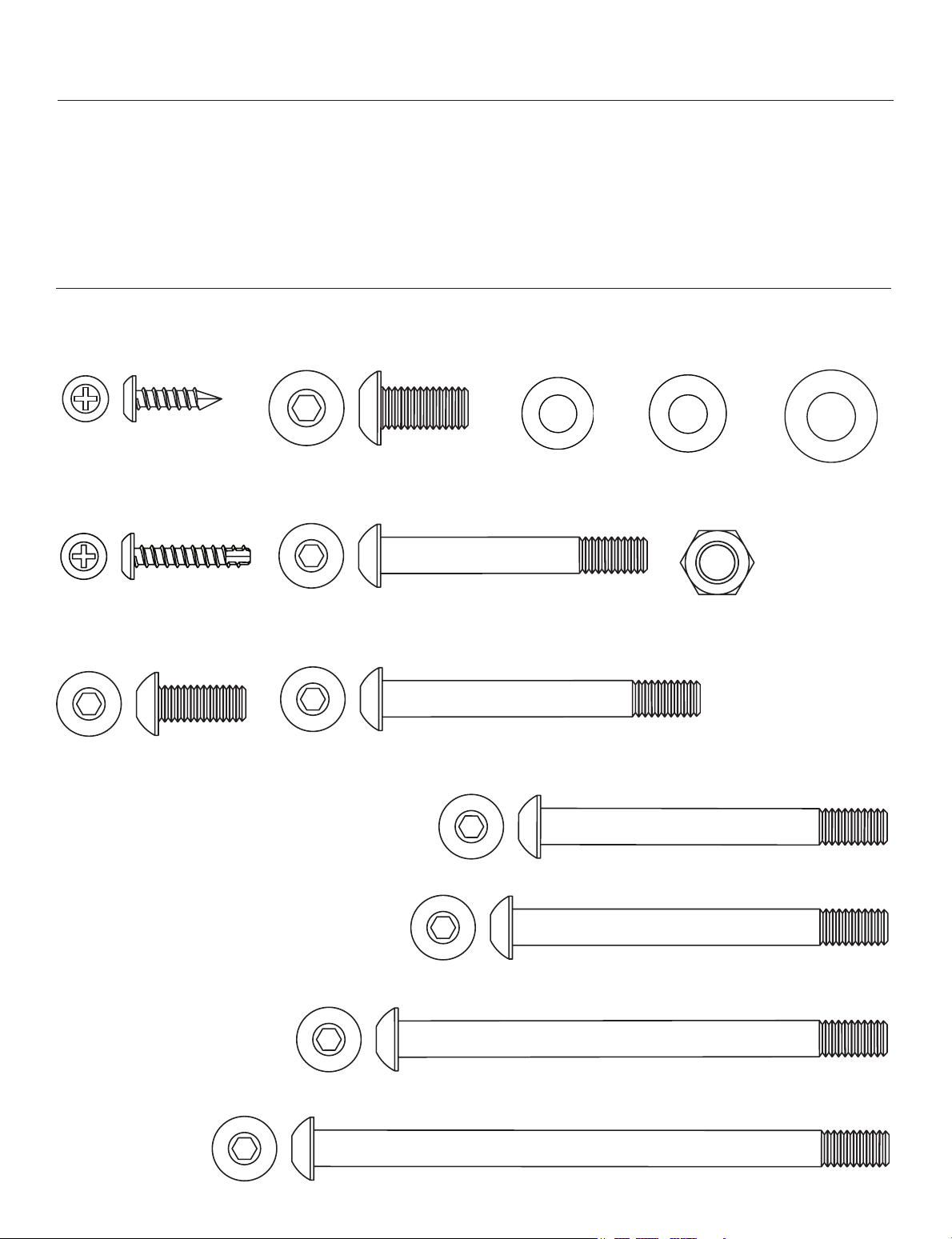
Hardware Guide
Tools You Will Need
You will need the following tools to complete the assembly of your Bowflex Sport® home gym. If you don’t have these tools,
you can find them at any hardware or department store for a reasonable price.
• 1/2" combination wrench
• 9/16" combination wrench
• Phillips screw driver
Item #: A
Qty.: 4
Descr: #10 X .75”
Phillips Head Screw
B
Item #:
Qty.: 3
Descr: #10 X 1"
Item #:
Qty.:
Descr: 5/16" X 3/4"
Phillips Head Screw
C
8
Button Head Screw
• Rubber mallet (optional)
• Utility Knife or Scissors
Note: Drawings are actual size
• (2) Allen Wrenches (included
Item #:
E
Qty.: 10
Descr: 3/8" X 3/4"
Button Head Screw
Item #: F
Qty.: 1
Descr: 3/8" X 2 1/2"
Button Head Screw
Item #: G
Qty.: 1
Descr: 3/8" X 2 3/4"
Button Head Screw
)
Item #: L
Qty.: 3
Descr: 1/4" Flat Washer
Item #:
Qty.: 8
Descr: 5/16" Flat Washer
M
Item #: O
Qty.: 18
Descr: 3/8" Nylock Nut
Item #
N
Qty.:
46
Descr: 3/8" Flat Washer
Item #:
K
Qty.: 4
Descr: 3/8" X 5"
Button Head Screw
4
Item #:
J
Qty.: 2
Descr: 3/8" X 4 1/4"
Button Head Screw
Item #:
Qty.: 8
Descr: 3/8" X 3"
Item #: I
Qty.: 2
Descr: 3/8" X 3 1/4"
H
Button Head Screw
Button Head Screw
Page 7
Assembly Guide
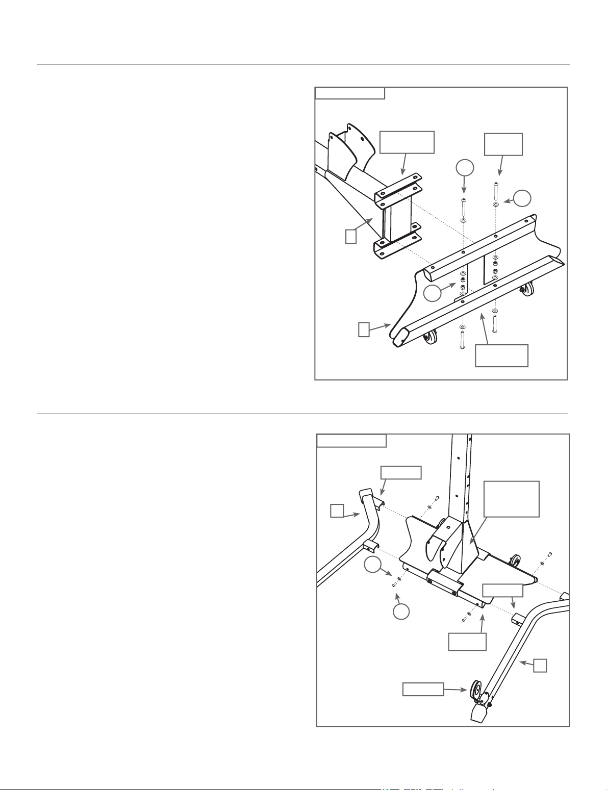
Step 1 - Attach the Lower Lat Tower to the Base
Platform
Locate the following items:
• Item #1 - Lower Lat Tower
• Item #2 - Base Platform
• Item #H - (4) 3/8" X 3" Button Head Screws
• Item #N - (8) 3/8" Washers
• Item #O - (4) 3/8" Nylock Nuts
Set the Base Platform (Item #2) onto the floor as shown
in Figure 1. Line up the bolt holes in the mounting channels
on the Lower Lat Tower (Item #1) with the holes in the Base
Platform tubes.
Place (4) 3/8" Washers (Item #N) over the ends of (4) 3/8" X 3"
Button Head Screws (Item #H) - one washer per screw.
Insert the forward screws through the bolt holes in the Lower
Lat Tower and Base Platform first, then tip the Base Platform
back to install rear screws. Place (4) 3/8" Washers over the
ends of the screws, one washer per screw, and secure using
(4) 3/8" Nylock Nuts (Item #O), as shown in Figure 1
.
Figure 1
1
Mounting
Channels
O
2
H
Base Platform
Forward
Screws
Tubes
N
Completely tighten hardware installed during Step 1.
Step 2 - Attach the Base Legs to the Base Platform
Locate the following items:
• From Step 1 - Base Platform/Lower Lat Tower Assembly
• Item #3 - Base Right Leg - Do not unwrap cables!
• Item #4 - Base Left Leg - Do not unwrap cables!
• Item #E - (4) 3/8" X 3/4" Button Head Screws
• Item #N - (4) 3/8" Washers
With the Base Platform/Lower Lat Tower Assembly (from
Step 1) on the floor, insert the stems from each Base Leg
into the tube ends on the Base Platform, as shown in Figure
2. Make sure to orient the 2 pulleys upward.
Carefully line up the two bolt holes on each Leg with the
corresponding holes on the Base Platform/Lower Lat Tower
Assembly.
Place (4) 3/8" Washers (Item #N) over the ends of (4) 3/8" X 3/4"
Button Head Screws (Item #E) - one washer per screw. Loosely
secure the Base Legs to the Base Platform Assembly with the
screws and washers as shown in Figure 2
.
Figure 2
4
Stems
Base Platform/
Lower Lat
Tower
Assembly
N
Stems
E
Tube
Ends
3
Pulleys
Completely tighten hardware installed during Step 2.
5
Page 8
Assembly Guide
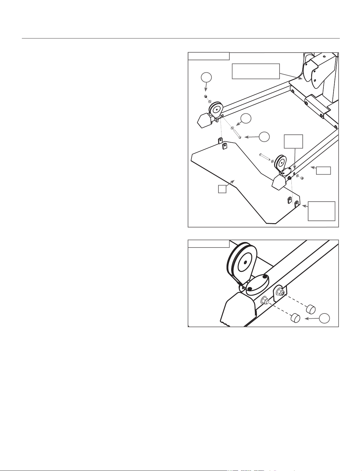
Step 3 - Attach the Squat Platform to the Main
Assembly
Locate the following items:
• From Step 2 - Base Platform/Lat Tower (Main) Assembly
• Item #5 - Squat Platform
• Item #I - (2) 3/8" X 3 1/4" Button Head Screws
• Item #N - (4) 3/8" Washers
• Item #O - (2) 3/8" Nylock Nuts
• Item #Q - (4) Bolt Covers
With the Base Frame/Lower Lat Tower (Main)
Assembly (from Step 2) on the floor, carefully lift up the
front of the unit, then slide the Squat Platform (Rubberpad side down) underneath both Legs.
Line up the bolt holes in the brackets on the Squat
Platform with the bolt holes on each Leg (directly
behind the pulleys), as shown in Figure 3a.
Place (2) 3/8" Washers (Item #N) over the ends of (2) 3/8" X 3
1/4" Button Head Screws (Item #I) - one washer per screw.
Insert the screws through the lined-up holes as shown,
then place (2) 3/8" Washers and (2) 3/8" Nylock Nuts (Item
#O) over the end of each screw, securely tightening them in
place.
Figure 3a
O
Figure 3b
Base Platform/Lower
Lat Tower Assembly
N
5
I
Bolt
Holes
Leg
Squat
Platform
Brackets
Completely tighten hardware installed during Step 3.
Place (2) Bolt Covers (Item #Q) over the Nylock Nuts installed
in this step - one cover per nut. Then, place (2) additional
Bolt Covers over the J-bolts, one cover per bolt, that attach
the Pulleys to the Leg, as shown in Figure 3b
.
Q
6
Page 9

Assembly Guide
Step 4 - Attach the Chest Bar with Pulleys to the
Main Assembly
Locate the following items:
• From Step 3 - Main Assembly
• Item #6 - Chest Bar w/ Pulleys - Do not unwrap cables!
• Item #K - (2) 3/8" X 5" Button Head Screws
• Item #N - (4) 3/8" Washers
• Item #O - (2) 3/8" Nylock Nuts
Line up the bolt holes in the brackets on the Chest Bar
with Pulleys (Item #6) with the lowest bolt holes on the
Lower Lat Tower, as shown in Figure 4. Pulleys should be
oriented forward.
Place (2) 3/8" Washers (Item #N) over the end of (2) 3/8” X
5" Button Head Screws (Item #K) - one washer per screw.
Insert the screws through the lined up holes in the Chest
Bar with Pulleys and the Lower Lat Tower, and secure each
screw by placing (1) 3/8" Washers and (1) 3/8" Nylock Nuts
(Item #O) over the end of each screw.
Completely tighten hardware installed during Step 4.
Figure 4
K
N
Chest Bar
Brackets
O
Base Platform/
Lower Lat Tower
Assembly
6
Step 5 - Attach the Seat Bracket to the Seat Pad
Locate the following items:
• Item #7 - Seat Pad
• Item #8 - Seat Bracket
• Item #C - (4) 5/16" X 3/4" Button Head Screws
• Item #M - (4) 5/16" Washers
Place the Seat Pad (Item #7) on the floor, cushion-side down.
Position the Seat Bracket (Item #8) so the cut-out is toward the
angled edge of the Seat Pad. Align the four holes in the Seat
Bracket with the four holes in the Seat Pad.
Place (4) 5/16" Washers (Item #M) over (4) 5/16" X 3/4" Button
Head Screws (Item #C) - one over each screw, and use those
screws to secure the Seat Bracket to the Seat Pad.
Completely tighten hardware installed during Step 5.
Figure 5
M
7
C
8
Cut-out
Angled
Edge
7
Page 10

Assembly Guide
Step 6 - Attach the Seat Rail to the Seat Assembly
Locate the following items:
• From Step 5 - Seat Pad/Seat Bracket Assembly
• Item #9 - Seat Rail
Undo the twist ties from the Rail Pivot Bushings and remove the
Bushings. Set aside until the end of this step.
Line up the Seat Rail (Item #9) with the Seat Assembly (from Step
5). Orient the Seat Rail so that the Pull Pin on the Seat Bracket is
on the same side as the holes in the Seat Rail.
Pull out the Pull Pin on the Seat Bracket, and then insert the
Seat Rail through the Seat Bracket, (see Figure 6).
To adjust the Seat, slide the Seat until the Pull Pin is aligned
with one hole, then release the Pull Pin into the hole.
Once you have attached the Seat Assembly to the Seat Rail,
reinstall the Rail Pivot Bushings that you removed at the
beginning of this step.
Note: See Step 22 to adjust the Seat Bracket.
Figure 6
Rail Pivot
Bushings
9
Seat Pad/Seat
Bracket Assembly
Holes in the
Seat Rail
Pull Pin
Step 7 - Attach the Rear Leg to the Rear Leg Cross
Tube
Locate the following items:
• Item #10 - Rear Leg - Do not unwrap cables!
• Item #11 - Rear Leg Cross Tube
• Item #H - (2) 3/8" X 3" Button Head Screws
• Item #N - (4) 3/8" Washers
• Item #O - (2) 3/8" Nylock Nuts
Line up the holes in the bracket on the Rear Leg (Item #10) with
the holes in the Rear Leg Cross Tube (Item #11) as shown in
Figure 7.
Place (2) 3/8" Washers (Item #N) over the end of (2) 3/8" X 3"
Button Head Screws (Item #H) - one per each screw. Insert
the screws through the lined up holes, and secure by placing
(1) 3/8" Washer and (1) 3/8" Nylock Nut (Item #
of each screw, as shown in Figure 7
.
Completely tighten hardware installed during Step 7.
O) over the end
Figure 7
10
O
Rear Leg
Bracket
N
H
11
8
Page 11

Assembly Guide
Step 8 - Attach the Rear Leg to the Seat Rail
Locate the following items:
• From Step 6 - Seat Rail Assembly
• From Step 7 - Rear Leg Assembly
• Item #J - (1) 3/8" X 4 1/4" Button Head Screw
• Item #N - (2) 3/8" Washers
• Item #O - (1) 3/8" Nylock Nut
• Item #Q - (2) Bolt Covers
Undo the twist ties from the Pivot Bushings on the end of the Rear
Leg Assembly (from Step 6), but do not remove the Bushings.
Note: When attaching the Rear Leg Assembly (from Step 7) to
the Seat Rail Assembly, rotate the Rear Leg forward (as shown
in Figure 8b), to allow the Leg Latch to engage with the Seat
Rail Pull Pin.
Align the holes on the End Bracket of the Seat Rail Assembly with
the middle holes on the Rear Leg Assembly, (see Figure 8).
Place (1) 3/8" Washer (Item #N) over the end of (1) 3/8" X 4 1/4"
Button Head Screw (Item #J). Insert the screw through the lined
up holes and then loosely secure on the opposite side by placing (1)
3/8" Washer and (1) 3/8" Nylock Nut (Item #
Do not over-tighten hardware from Step 8.
Note: Tighten the nylock nut enough that the threads of the screw
extend through the nylock nut, but loosely enough that the Leg
Assembly can move freely.
O) over the end.
Figure 8
Rail
Assembly
Figure 8b
Rail
Assembly
J
Rear Leg
Assembly
Leg Latch
Bracket
N
End
Middle
Hole
O
At this time, place (1) Bolt Cover (Item #Q) over the Nylock
Nut installed during Step 8, place 1 bolt cover over the
Nylock Nut going through the rear leg pulley.
Once you have completed Step 8, rotate the Rear Leg back until
it engages the Seat Rail Pull Pin.
Seat Rail
Pull Pin
Rear Leg
9
Page 12

Assembly Guide
Step 9 - Attach the Seat Rail to the Main Assembly
Locate the following items:
• From Step 4 - Main Assembly
• From Step 8 - Seat Rail Assembly
• Item #12 - Seat Rail Knob
• Item #J - (1) 3/8" X 4 1/4" Button Head Screw
• Item #N - (2) 3/8" Washers
• Item #O - (1) 3/8" Nylock Nut
• Item #Q - (1) Bolt Cover
Align the holes on the Seat Rail Assembly (from Step 8)
with the holes in the Rail Bracket on the Main Assembly
(from Step 4), as shown in Figure 9
Insert the Seat Rail Assembly into the Seat Rail Bracket,
and then place (1) 3/8" Washer (Item #N) over the end of (1)
3/8" X 4 1/4" Button Head Screw (Item #J). Insert the screw
through the aligned holes, as shown, and place (1) 3/8"
Washer and (1) 3/8" Nylock Nut (Item #
screw to secure.
Do not over-tighten the hardware from Step 9.
.
O) over the end of the
Figure 9
Assembly
Seat Rail
Rail
Bracket
J
Main
Assembly
12
N
O
Note: Tighten the nylock nut enough that the threads of the screw
extend through the nylock nut, but loosely enough that the Seat
Rail Assembly can move freely.
At this time, place (1) Bolt Cover (Item #Q) over the Nylock
Nut installed during Step 9. Then, thread the Seat Rail Knob
(Item #12) into the top hole on the Seat Rail Bracket, as
shown in Figure 9, but do not over-tighten.
10
Page 13

Assembly Guide
Step 10 - Attach the Leg Extension Pivot Tube
Locate the following items:
• Item #13 - Leg Extension Pivot Tube
• From Step 9 - Main Assembly
• Item #30 - Lock Out Pin
• Item #G - (1) 3/8" X 2 3/4" Button Head Screw
• Item #N - (2) 3/8" Washers
• Item #O - (1) 3/8" Nylock Nut
• Item #Q - (1) Bolt Cover
Undo the twist ties from the Pivot Bushings. Align the holes
located on the “curve” of the Leg Extension Pivot Tube (Item #13)
with the holes on the bracket of the Rear Leg, as shown in Figure
10a.
Place (1) 3/8" Washer (Item #N) over the end of (1) 3/8" X
2 3/4" Button Head Screw (Item #G). Thread the screw
through the aligned holes and bushings and secure by
placing (1) 3/8" Washer and (1) 3/8" Nylock Nut (Item #O)
over the end of the screw, as shown in Figure 10a.
Do not over-tighten hardware from Step 10.
Place (1) Bolt Cover (Item #Q) over the Nylock Nut installed
during Step 10.
Note: When storing the Rail Assembly, insert the Lock Out Pin
(Item #30) through the holes in the Pivot Tube to temporarily
hold the Leg Extension in place while folding the Rail up (see
Figure 10b).
Figure 10a
Figure 10b
30
N
“Curve”
13
Holes
G
Bracket
O
Leg
Extension
Rear Leg
11
Page 14

Assembly Guide
Step 11 - Attach the Rollers to the Leg Extension
Locate the following items:
• From Step 10 - Main Assembly
• Item #14 - Foam Rollers
• Item #15 - Foam Roller End Caps
• Item #16 - Short Chrome Roller Tubes
• Item #17 - Long Chrome Roller Tube
• Item #18 - Roller Tube Spacers
There are (3) Chrome Roller Tubes on the Leg Extension.
Place the Long Chrome Roller Tube (Item #17) through the
hole closest to the Seat.
There are two holes possible in the Leg Extension Pivot
Tube for the lower of the Short Chrome Roller Tubes (Item
#16). Select the correct lower hole for your height - the
Roller should rest on your lower shin above the ankle. Insert
the (3) Chrome Roller Tubes through the holes on the Leg
Extension Pivot Tube and Rear Leg, as shown in Figure 11
Slide (2) Roller Tube Spacers (Item #18) over each end of the
Long Chrome Roller Tube. Then, slide (2) Foam Rollers (Item
#14) over the ends of all three tubes. Cap the Roller Tubes
with the (6) Foam Roller End Caps (Item #15).
.
Figure 11
15
14
18
17
16
Note: Use a Rubber Mallet to secure the End Caps.
Step 12 - Attach Leg Cable to the Leg Extension
Locate the following items:
• From Step 11 - Main Assembly
• Item #AA - (1) Leg Cable
• Item #F - (1) 3/8" X 2 1/2" Button Head Screw
• Item #N - (2) 3/8" Washers
• Item #O - (1) 3/8" Nylock Nut
• Item #Q - (1) Bolt Cover
Slide the hooked end of the Leg Cable beneath the Leg
Extension Pulley and into the hole on the Leg Extension Pivot
Tube, as shown in Figure 12.
Place (1) 3/8" Washer (Item #N) over the end of (1) 3/8" X 2
1/2" Button Head Screw (Item #F). Thread the screw through
holes in the Leg Extension and cable end. Place (1) 3/8"
Washer and (1) 3/8" Nylock Nut (Item #O) over the end of the
screw, as shown in Figure 12, and tighten.
Completely tighten hardware installed during Step 12.
Figure 12
F
N
AA
O
Place (1) Bolt Cover (Item #Q) over the Nylock Nut
installed during Step 12.
Page 15

Assembly Guide
Step 13 - Assemble the Leg Extension Seat
Locate the following items:
• Item #19 - Leg Extension Seat Pad
• Item #21 - Leg Extension Seat Support Tube
• Item #C - (4) 5/16" X 3/4" Button Head Screws
• Item #M - (4) 5/16" Washers
Place the Leg Extension Seat Pad (Item #19) cushion-side
down. Align the holes in the Leg Extension Seat Support
Tube (Item #21) with the holes on the underside of the Seat
Pad.
Place (4) 5/16" Washers (Item #M) over (4) 5/16" X 3/4"
Button Head Screws (Item #C) - one over each screw. Insert
the screws through the aligned holes, and tighten.
Completely tighten hardware installed during Step 13.
Figure 13
Rail
Bracket
19
C
21
M
Seat
Curved
Edge
13
Page 16

Assembly Guide
Figure 14
Step 14 - Attach the Leg Extension Seat to the Main
Assembly
Locate the following items:
• From Step 13 - Leg Extension Seat Assembly
• From Step 12 - Main Assembly
The Leg Extension Seat Assembly is removable, and can be
attached to the Rear Leg Assembly easily by placing the Rail
Bracket Hooks over the Rear Rollers.
Place the Rail Bracket Hooks onto the Roller Tube Spacers
(sandwiched between the Rear Leg and the Foam Rollers).
Once the Support Tube Bracket Hooks connect with the
Roller Tube Spacers, slightly “roll” the back edge of the Seat
down to lock into place.
Warning: For your safety, always ensure that the Support
Tube Bracket Hooks fully engage with the Roller Tube
Spacers.
To remove the Leg Extension Seat Assembly, reverse
this procedure.
Support Tube
Bracket Hooks
Roller Tube
Spacers
Leg Extension
Seat
Back Edge
Step 15 - Attach the Lat Cross Bar to the Upper
Lat Tower
Locate the following items:
• Item #22 - Lat Cross Bar - Do not unwrap cables!
• Item #23 - Upper Lat Tower
• Item #H - (2) 3/8" X 3" Button Head Screws
• Item #N - (4) 3/8" Washers
• Item #O - (2) 3/8" Nylock Nuts
Align the holes in the Lat Cross Bar (Item #22) with the
holes in the bracket on the Upper Lat Tower (Item #23).
Place (2) 3/8" Washers (Item #N) over the ends of
(2) 3/8" X 3" Button Head Screws (Item #H) - one washer
per screw. Thread the screws through the aligned holes,
then secure by placing (1) 3/8" Washer and (1) 3/8" Nylock
Nut (Item #
O) over each screw and tighten.
Completely tighten hardware installed during Step 15.
Figure 15
22
O
N
H
Lat
Tower
Bracket
23
14
Page 17

Assembly Guide
Step 16 - Attach the Upper Lat Tower to the Lower
Locate the following items:
• From Step 15 - Upper Lat Tower Assembly
• From Step 14 - Main Assembly
• Item #E - (6) 3/8" X 3/4" Button Head Screw
• Item #N - (6) 3/8" Washers
Carefully insert the end of the Upper Lat Tower into the
open end of the Lower Lat Tower. Align the holes on the
Upper Lat Tower with the holes on the Lower Lat Tower.
Place (6) 3/8" Washers (Item #N) over the ends of (6) 3/8" X
3/4" Button Head Screws (Item #E) - one washer per screw.
Thread the screws into the aligned holes, as shown in
Figure 16
Completely tighten hardware installed during Step 16.
.
Figure 16
Upper Lat
Tower
E
Lower Lat
Tower
N
Step 17 - Attach the Rod Box with Power Rods® to
the Rod Box Frame
Locate the following items:
• Item #24 - Rod Box Frame
• Item #25 - Rod Box with Power Rods®
• Item #B - (3) #10 X 1" Phillips Head Screws
• Item #L - (3) 1/4" Washers
Place the Rod Box Frame (Item #24) and Rod Box with
Power Rods® (Item #25) onto one side as shown in
Figure 17. Slide the Rod Box with Power Rods® into the
Rod Box Frame until the Rod Box is completely seated in the
Rod Box Frame.
Place (3) 1/4" Washers (Item #L) over the ends of (3) #10 X 1"
Phillips Head Screws (Item #B) - one washer per screw.
Insert the screws through the slot on the Rod Box Frame and
thread into the holes in the Rod Box with Power Rods
Completely tighten hardware installed during Step 17.
®.
Figure 17
24
Slot
25
L
B
15
Page 18

Assembly Guide
Step 18 - Attach the Rod Box Frame to the Lat Tower
Locate the following items:
• From Step 16 - Main Assembly
• From Step 17 - Rod Box/Frame Assembly
• Item #K - (2) 3/8" X 5" Button Head Screws
• Item #N - (4) 3/8" Washers
• Item #O - (2) 3/8" Nylock Nuts
Align the bolt holes on the Rod Box brackets with the bolt
holes on the Lat Tower above the Chest Bar , as shown in
Figure 18
Place (2) 3/8" Washers (Item #N) over the ends of
(2) 3/8" X 5" Button Head Screws (Item #K) - one washer per
screw. Insert the screws through the aligned holes. Place (1)
3/8" Washer and (1) 3/8" Nylock Nut (Item #O) over the end of
each screw and tighten.
Completely tighten hardware installed during Step 18.
.
Figure 18
K
Chest Bar
Rod Box
N
Brackets
O
Step 19 - Attach the Faceplate to the Main
Assembly
Locate the following items:
• Item #26 - Faceplate
• From Step 18 - Main Assembly
• Item #A - (2) #10 Phillips Head Screws
Position the textured side of the Faceplate (Item #26) against
the Lower Lat Tower. Insert the plastic “stems” through the
corresponding holes on the Lower Lat Tower, as shown in Figure
19. You may need to push the Power Rods® out of the way to
insert the screws into the holes.
Attach the Faceplate to the Lower Lat Tower by threading (2)
#10 Phillips Head Screws (Item #A) into the “stems”.
Do not completely tighten hardware installed during Step 19 tighten screws approximately 1/2 of completion. Hardware will
be tightened during Step 20.
Figure 19
Faceplate
“Stems”
26
A
16
Page 19

Assembly Guide
Step 20 - Attach the Faceplate Back Panels
Locate the following items:
• Item #27 - Faceplate Right Back Panels
• Item #28 - Faceplate Left Back Panels
• From Step 19 - Main Assembly
• Item #A - (2) #10 Phillips Head Screws
Slide each Faceplate Back Panel (Items #27 & 28), textured
side out, against the textured (back) side of the Faceplate.
The screw heads of the (2) Phillips Head Screws installed
during Step 19 should allow the Back Panels to slide beneath
them until the panels meet in the center..
Secure the Panels using (2) #10 Phillips Head Screws (Item
#A), as shown in Figure 20, attaching one side at a time.
Completely tighten hardware installed during Steps 19 & 20.
Figure 20
27
Main
Assembly
28
A
Step 21 - Tighten Lower Bolt on the Seat Bracket
Locate the following items:
• From Step 5 - Seat Assembly (underneath)
Using an Allen Wrench (included) and a combination wrench,
tighten the top nut & bolt on the Seat Assembly (see Figure
21). Take care that the Seat Assembly can still freely slide
without resistance along the Seat Rail when you are seated.
Note: The Seat Assembly will have some resistance when
rolling if no one is seated.
Take care not to overtighten hardware from Step 21.
Figure 21
Nut
17
Page 20

Assembly Guide
Step 22 - Attach the Bench to the Seat Assembly
Locate the following items:
• Item #29 - Bench Pad
• From Step 6 - Seat Assembly
The Bench easily attaches and releases from the Seat. To
attach the Bench, insert the half hinge on the end of the
Bench into the half hinge on the seat. To remove the
Bench, lift up on the long portion and pull away from Seat.
Note: At this time, carefully go over your entire
Bowflex
screws, nuts and other hardware securely
before exercising on your Bowflex
Home Gym.
Steps 23 through 26 illustrate how to route and connect the
Cables to your new Bowflex
Sport® Home Gym, tightening all
Sport®
Sport® Home Gym.
Figure 22
Seat
Assembly
29
Step 23 - Route the Rod Cables
Locate the following items:
• Item #S - (2) Hand Grips
• Item #V - (2) Snap Hooks
• Item #Y - (2) Rod Cables with (2) Snap Hooks (attached)
Unwrap the Cables from both Pulleys on the Chest bar.
Pull one end of the Cable from the Chest Pulley upwards.
Attach the Cable to one Rod Cap by hooking the Rod
Hook through the hole in the Rod Cap.
Then, fasten one Hand Grip to the Snap Hook on the
opposite end of the Cable, as shown in Figure 23
Repeat for remaining Chest Pulley Rod Cable.
.
Figure 23 - Rod Cables
Rod
Cap
Hand
Grip
Rod
Hook
Snap
Hook
18
Page 21

Assembly Guide
Step 24 - Route the Lat Cables
Locate the following items:
• Item #S - (2) Hand Grips
• Item #R - (1) Bent Lat Bar (optional)
• Item #Z - (2) Lat Cables with (2) Snap Hooks (attached)
Unwrap the Lat Cables with Snap Hooks from both Pulleys on
the Lat Cross Bar. Pull one end of the Cables down from the Lat
Cross Bar, and fasten to the Chest Cable Snap Hook.
Fasten the attached Snap Hook from the Lat Cable to a Hand
Grip or the Bent Lat Bar. Repeat for remaining Lat Cable.
Step 25 - Route the Leg Cables
Locate the following items:
• Item #AA - Leg Cable
• From Step 14 - Leg Extension Seat Assembly
Figure 24 - Lat Cables
Snap
Hook
Hand Grips
or Bent
Lat Bar
Figure 25 - Leg Cables
Snap
Hook
Unwrap the Cables from the Rear Leg Pulley.
Pull one end of the “Y” Cable away from the Rear Leg to fasten to
a Snap Hook on the Rod Cable.
Note: For this step, make sure your Leg Extension Seat is installed.
Step 26 - Route the Squat Cables
Locate the following items:
• Item #R - Squat Bar
Unwrap the Cables on each Base Leg Pulley. Pull one end of the
Cable up from the Leg Pulley, and fasten the Cable to a Snap
Hook on the Chest Bar.
Fasten the Snap Hook attached to the Squat Cables to the
corresponding Squat Bar “D” Ring.
Repeat for remaining Squat Cable.
CONGRATULATIONS! You have successfully completed assembly
of your Bowflex
to ensure that all fasteners are tight and everything is properly
assembled. Review all warnings that are affixed to the machine.
Sport® Home Gym! Please inspect your machine
Leg
Extension
Seat
Figure 26 - Squat Cables
Squat Bar
Snap
Hook
Snap
Hook
Snap
Hook
19
Page 22

IMPORTANT CONTACT NUMBERS
If you need assistance, please have both the serial number of your machine and the date of purchase available when you contact the
appropriate Nautilus office listed below.
OFFICES IN THE UNITED STATES:
E-mail: cstech@nautilus.com
• NAUTILUS INNOVATION CENTER
Nautilus, Inc.
1886 Prairie Way
Louisville, Colorado, USA 80027
Phone: 800-NAUTILUS (800-628-8458)
Fax: 800-898-9410
• TECHNICAL/CUSTOMER SERVICE
Nautilus, Inc.
World Headquarters
16400 SE Nautilus Drive
Vancouver, Washington, USA 98683
Phone: 800-NAUTILUS (800-628-8458)
Fax: 877-686-6466
• CORPORATE HEADQUARTERS
Nautilus, Inc.
World Headquarters
16400 SE Nautilus Drive
Vancouver, Washington, USA 98683
Phone: 800-NAUTILUS (800-628-8458)
INTERNATIONAL OFFICES:
For technical assistance and a list of distributors in your area,
please call or fax one of the following numbers.
• INTERNATIONAL CUSTOMER SERVICE:
Nautilus International S.A.
Rue Jean Prouvé 6
1762 Givisiez / Switzerland
Tel: + 41-26-460-77-77
Fax: + 41-26-460-77-70
Email: technics@nautilus.com
INTERNATIONAL OFFICES:
• SWITZERLAND OFFICE
Nautilus Switzerland S.A.
Tel: + 41-26-460-77-66
Fax: + 41-26-460-77-60
• GERMANY and AUSTRIA OFFICE
Nautilus GmbH
Tel: +49-2204-610-27
Fax: +49-2204-628-90
• ITALY OFFICE
Nautilus Italy s.r.l.
Tel: +39-031-51-10-86
Fax: +39-031-34-24-97
20
• UNITED KINGDOM OFFICE
Nautilus UK Ltd.
Tel: +44-1908-267-345
Fax: +44-1908-267-346
• CHINA OFFICE
Nautilus Representative Office
Tel: +86-21-523-707-00
Fax: +86-21-523-707-09
Page 23

Page 24

This manual is written and designed
SPORT
by industry professionals. If you
have any questions regarding your
Bowflex Sport® Home Gym or any
instructions found in this manual,
please call 1-800-605-3369 for
assistance.
©2004 Nautilus Inc. All rights reserved. 1400 N.E. 136th Ave., Vancouver, WA 98684.
Bowflex, Bowflex Sport, Power Rod and the Bowflex and Nautilus logos are either registered trademarks or trademarks of Nautilus, Inc.
 Loading...