

Page 1

1
2
3
4
B&W Group Ltd
Dale Road
Worthing West Susse x
BN11 2BH England
T +44 (0) 1903 22 1800
F +44 (0) 1903 22 1801
info@bwgroup.com
www.bwspeakers.com
B&W Group (UK Sales )
T +44 (0) 1903 22 1 500
E uksales@bwgroup.com
B&W Group North Ame rica
T +1 978 664 2870
E marketing@bwgroupusa .com
B&W Group Asia
T +852 2 790 8903
E info@bwgroup.hk
Kevlar is a registe red trademark of DuPont. Nautilus a nd
Matrix are registered trademarks of B&W Group Ltd.
Cobex is a registere d trademark of Wardle Sto reys Ltd.
Design Thomas Manss & Company. Pri nted in the UK.
B&W Group Ltd reserv es the righ t to amend details of the
specification without notice in line with technical de velopments.
Copyright © B&W Gro up Ltd. E&O E
Page 2

The Nautilus loudspeakers you have invested
in are an exact match to the first production
loudspeakers. Hand-built and tested, serial
marked and packaged individually, the refusal
to compromise at any stage from concept to
reality is a hallmark quality of Nautilus and your
guarantee of absolute satisfaction.
Nautilus owner's manual
Loudspeaker B
Bass driver
Lower midrange driver
Upper midrange driver
High frequency driver
Crossover B
Loudspeaker A
Bass driver
Lower midrange driver
Upper midrange driver
High frequency driver
Crossover A
Quality Control
Line Insp.
Tester
Packer
Random Insp.
Page 3
Contents
Introduct ion 5
Enclosure 6
Drive u nits 7
Crossover 7
Unpackin g 8
Position ing 10
Installa tion 10
Cable c onnection 11
Fine tu ning 12
Aftercare 12
Specific ation 13
Safety instructions 14
Page 4

5
B&W mon itors are wi dely conside red to be
the ben chmark in m usic reproduct ion by
professio nal musicians and audiop hiles alike.
The Mat rix #801 ha s become th e industry
standard monitor in recording stu dios around
the wor ld, and it would be e asy to rest on our
developm ent laurels.
However, th e team of audio scienti sts at
B&W’s Researc h Laboratorie s at Steyni ng
are perf ectionists. For them, t here are
always areas which could be im proved
upon or refined.
Company founder, John Bowers, was
an exem plar of the type. For him, the m ost
glaring compromise i n loudspeaker design
lay in the cabinet . The stand ard rectangula r
enclosure only parti ally achieves its goal
of abso rbing the re ar radiation from the
drive u nit.
Worse, i t contribute s resonances and
reflectio ns from the inside, and diffraction
and refl ection from the outside.
The B&W breakthrough of Matrix cabinet
construc tion offered a significant improvement
to the panel stiffn ess of the rectangular box,
but ult imately, the so lution, John felt, was to
remove t he cabinet completely a nd create
a dipol e source. Sa dly, time and ill-health
interven ed to preven t John Bowe rs from
explorin g this aven ue of researc h further.
Custody of this wo rk was pass ed to Matri x
inventor and top a coustic desi gner, Laurence
Dickie, with an en viable record of transduc er
and cab inet problem solving. La urence had
been ex perimenting with drivers mounted
in the curved surf ace of a c ylinder and
encounte red results n ot dissimilar to those
of the dipole.
Namely, tha t external cabinet effec ts could
be virt ually elimin ated and th e intrinsic sound
of the unit heard.
Introduction
He used a ring m agnet outside the coil with
a thin- walled cylin drical pole piece to a llow
a smoot h transition from dome to enclosure.
Only on e type of enclosure wil l provide
absolute freedom from aberration – the infi nite
pipe or waveguide.
Exciting ly, it b ecame possib le to imagi ne
that an entirely wa veguide-based system
could a ctually work . Research s howed
that th e exponentia lly tapered pipe was an
even be tter absorbe r than the cylinder. So
complete was its a bsorbing act ion that th e
pipe co uld be left open or c losed.
This wa s the breakt hrough. Therea fter, the
usual d isciplines o f the acous tic engineer’s ar t
came in to play. Juggli ng the varia bles of dri ver
diameter, d ispersion, bre ak-up, excur sion,
practica lity, and of c ourse, econom ics.
It was decided tha t the syste m should
be four-w ay with 300m m (12in), 1 00mm
(4in), 50mm (2in) and 25mm (1 in) units – all
mounted in tapered lines within a diffracti on
limiting enclosure.
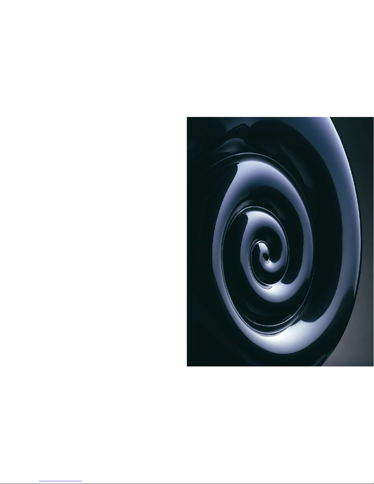
The enc losure evolve d from the original
cylinder into the sleek rolling vent desig n
you hav e purchased. The massive rolling
vent di sposes of re ar bass dri ver radiatio n,
whilst the exponent ial transmiss ion pipes
loading the other drive units effectively deal
with in ternal refle ction and e xternal diffr action
at mid and high frequencies.
The dri ve for soni c purity is reinforced b y
using a n active cro ssover desig n allowing
separate amplificatio n of each drive unit,
cutting out compone nt crosstalk and driver
inter-reacti on. Overall, the elimin ation
of stra ight lines defeats diffr action and
helps a chieve virtu ally transpare nt music
reproducti on.
What res ults is arg uably the m ost musical
loudspea ker ever ma de.
Page 5

6
Exponenti al line loa ding is use d for all four
drive u nits, primari ly to achie ve freedom f rom
resonance and reflecti on, but als o for the
damping effect on t he fundamenta l resonance
in the low frequenc ies.
The two dome units are tightly coupled to
their re spective wave guides via a hollow pole
magnet which causes minimal dis continuity t o
the adv ancing wave front.
A hollow po le magnet is also to be found
behind the lower mid diaphragm supported by a
chassis which itself forms the first 50mm of the
wave guide. The tube to which this is attached is
shaped to s mooth the transition from the chassis.
The dis tinctive natu ral appearan ce of Nauti lus
is deri ved from the best compro mise of fol ding
a tapere d tube to save space whilst maint aining
the hig hest curvature -to-width ra tio. Traditionall y,
folded pipes have involved many 180° bends
which h ave serious frequency dep endent
transmiss ion propertie s.
Enclosure
Each dr ive unit ha s been deve loped to
operate as a pisto n within it s intended
frequency band, with two octave s between
the upp er roll-off a nd the firs t sign of breakup mode s. Extensive use of al uminium in
the dia phragms make s this poss ible. All
voice c oils are wou nd on polyi mide formers
to elim inate eddy-c urrent losses, which are
particul arly serious at high f requencies.
A 9.5kg (21lbs) ma gnet with a 100mm
(4in) v oice coil a cts as the massive mot or of
the 300 mm (12in) b ass unit. T his, when u sed
in the exponential line enclos ure, results in
a high- pass behavio ur so over-dam ped that
the tra ditional sec ond-order char acteristic
is repla ced by two distinct fi rst-order slo pes
and no stored energ y.
A 250 micron one-pi ece aluminiu m cone/
centre d ome ensures coherent moti on to
beyond 1.5kHz. From 220Hz to 8 80Hz,
a 100mm flat-fronted unit is e mployed to
prevent the gentle cavity resona nce found
in conv entional con e units at around 2kHz
interfer ing with th e output fro m the upper
midrange unit. A r are earth ma gnet assembl y
with ho llow pole i s used to minimise the
obstruct ion to the rear radiati on from
the dia phragm.
Two domed u nits of ano dised alumin ium
of simi lar construc tion, 50mm and 25mm
in diam eter, handle th e 880Hz-3.5kH z and
3.5kHz-2 5kHz ranges respectively. All drive
units a re completely mounted on silicone
rubber O-rings to decouple the m from
the cab inet.
Drive units Crossover
The div ision of th e signal in to the four required
bandwidt hs is accom plished in the Nautilus
Active Crossover via totally no nresonant
circuitry. B oth inputs and outputs offer
single and balanced operation, the latter
being p articularly useful in n oisy electric al
environme nts, although a slight subjective
improveme nt has been observed w hen
using b alanced sign al interconnec tions at
every s tage.
With s uitable pre- and power amplifiers,
one uni t is required for each loudspeaker
and sho uld be site d close to the power
amplifie rs. A power supply con nection for
each cro ssover is re quired.
10mm th ick Glass R einforced Plas tic (GRP) h as
been us ed for the exterior su rface which, when
coupled with the d oubly curved shape, resul ts
in an extremely sti ff enclosure. The inner turns
of the spiral are bounded by a foam fill ed GRP
which b races the o pposite faces of the sn ail in
a manne r similar t o the Matri x type enclo sure
perfected by B&W.
The ext ernal form of the Naut ilus has be en
achieved using a b lend of han d-built formi ng
and adv anced CAD t echnology bor rowed from
the aut omotive indus try. This enabl es B&W to
maintain mathematical accuracy o f the wave
guide a nd to produc e the final mould tool to
submillim etric accura cy.
The hig h gloss sur face finish is the resu lt
of usin g a two-par t acrylic p aint with a deep
lacquer coat for l ustre and du rability. A 50kg
block o f polished terrazzo type material s upports
the com plete mollusc .
Important: your dealer must
check that the serial number
located at the rear o f each
crossover u nit matches that
of the lo udspeaker – and that
the stated voltage is correct
for your mains supply.
Page 6

8
9
A pair of Nautilus is supplie d in three crates.
The two larger cra tes each co ntain one Na utilus
loudspeak er and one active cross over. One of
the lar ge crates c ontains the accessory pa ck
and is marked as such. The s mall crate contains
two sto ne plinths.
Lay eac h crate fla t on the g round. Open
the lid s using a number 2 po zidrive screw driver.
Unscrew all screws b efore lifting the lid o ff of
the cra tes.
Begin w ith the sma ll crate, w hich holds t he plinth
to supp ort the prod uct. Remove the lid an d
card sep arator and set aside. The plinth weights
approximat ely 50kg, s o it requires two people
to lift . One perso n should pl ace a hand into the
slot in the plinth and raise one end. T he second
person should place one hand on either si de of
the pli nth at the opposite en d from the slot. Lift
the pli nth from the crate and gently plac e it as
close a s possible to its fina l installatio n position.
(Please note: the cable cut-out end belong s at
the bac k of the s peaker) Repe at these ste ps for
the sec ond plinth.
Place e ach large c rate alongsid e the plint h or as
close a s possible to the plin th. Unscrew all the
screws h olding the lid on the crate. Remo ve the
lid and set aside. Remove the strap, leng th of
wadding and protectiv e cover and place near by.
Remove the two pie ces of inte rnal packagi ng
using t he handholds provided. Re move the la yer
of fibre wadding to reveal the speaker, active
crossover and accesso ry pack. Pl ace the act ive
crossover and accesso ry pack asi de.
Depending on the p roximity of the plinth
to the large crate , it may b e possible to feed
the wire s through th e slot in the plinth before
Unpacking
removing the product from the cr ate. Feed t he
amplifier end of t he cable th rough the sl ot in
the top of the pl inth and gu ide it into the cable
cut-out at the rear of the pl inth. (Note: it
may be easier to feed the ca ble through by
supportin g the rear end of the plinth on the
metal ro d supplied in the acce ssory pack.
Remove the metal ro d once fini shed.)
Warning: do not lif t the speak er using an y of
its str aight tubes or the par t of the t weeter
enclosure forward of the split line.
One per son should grasp the t op of the speaker
under t he main bod y of the t weeter enclos ure.
The rig ht hand of the second person shoul d
support the speaker on the to p of the ro unded
part of the base, the left h and of the second
person should suppor t the speak er on the front
of the speaker bel ow the bass unit.
The per son supportin g the tweet er should l ift
the spe aker tilting it into a n upright po sition
while t he second p erson should support the
body of the speake r. Before removing th e
speaker from the cr ate, place the protective
cover o ver the fron t of the s peaker to p revent
damage during moving . Secure the cover with
the bel t provided, ensuring the length of wadding
is plac ed between the strap a nd the speak er to
protect the enclosure.
To remove th e speaker f rom the crat e, the
person supporting th e speaker s hould grasp
the thre aded spigot from which the cable
exits a t the base of the spe aker while the
other p erson support s the front and top o f the
speaker. Ens ure the pers on holding the spigot
is posi tioned to t he rear of the speaker so that
they ca n use their free hand to pull the cable
through the plinth as the spea kers is low ered
Attention : Please ca refully read through
these i nstructions i n full befo re starting
to unpa ck the produ ct. Unpacking should
be carr ied out by two people due to the
weight of the produ ct and awkw ardness
of the shape.
Note: R emove all w atches, rings , bracelets,
belts, and any oth er item of clothing tha t
might s cratch the product’s surface .
into po sition. Guide the spigot into the slot in
the pli nth.
Once th e speaker i s in place on the pli nth, feed
first a rubber was her and sec ondly a meta l
washer and finally a securing nut from th e
accessory pack over the free e nd of the cable
and sli de them as far as pos sible to th e
speaker end.
One per son should lean the sp eaker/plinth
combinati on forward t o expose th e underside
of the plinth. Whi le the firs t person sup ports
the wei ght of the speaker, the se cond person
should feed the wa shers over the spigot a nd
screw do wn the nut, tightening by hand on ly.
Carefully stand the speaker on its plinth upright
and pos ition it as required.
The dri ve units are delicate a nd easily d amaged.
Use the plastic co ver to prote ct them, fo r
example, if the sp eaker is to remain unus ed for
a long period, or if there are inquisitive children
about. Always secure the cover with the s trap
and len gth of wadd ing provided. We suggest you
retain t he packaging for future use.
Warning: The speaker drive units create
stray m agnetic field s that exte nd beyond
the bou ndaries of the enclosure.
We recomme nd you keep magnetically
sensitive articles ( CRT type tel evisions and
computer screens, com puter discs, audio
and vid eo tapes, s wipe cards, etc.) at le ast
1m (40i n) from the speaker. This d oes not
apply t o plasma or LCD screens .
These n otes will e xplain in d epth how to
unpack the plinth and speakers. Inside thi s
crate i s a copy o f the Nauti lus user ma nual
that wi ll show how to connect the Nautilu s
loudspeak er system.
Page 7

10
11
Cable connection
Connectio n to Nautil us is via an 8-core c able of
high pu rity silver on copper, term inated in b are
ends to allow the most direct connection to the
amplifier terminals.
It is generally ac cepted that the wires b etween
power a mp and driv er should b e as short as
possible, so we do not recomme nd that the
captive cable be l engthened in any way.
In the majority of cases it will be mos t
convenien t to locate the crossov er units in
close p roximity to the power a mplifiers, wi th
correspond ingly short line interco nnects. Each
cable s hould be co nnected direct ly to the
respective outputs of each ampli fier.
The lin e from pre-am plifier and crossover
is like ly to be c omparatively long and
should, therefore, be of high q uality and low
capacitan ce. It is further recom mended that the
balanced input of the crossover be used w ith
two-core screened cabl e – even if the pre-a mp
is sing le ended.
In the latter case , the screen and one c ore
should be joined a t the source end.
Detail of twin core d screened l ead connectin g
phono t o XLR plugs (pre-amp to x-over)
InstallationPositioning
Placement of any l oudspeaker ca n significan tly
influence the relativ e balance o f sound in the
listening seat and we recommend a degree o f
experimen tation. In general it will be fou nd that
Nautilus gives optim um results w hen “toed-in ”
to a g reater extent than in p revious syste ms,
set typ ically at a n angle of between 60° and
90°. Th is is due to the smoo th, wide di spersion
of Naut ilus which is capable of increasing the
relative significance of the sid e-wall reflec tion.
Another benefit of the dispersi on character istic
is the substantially increased l istening area in
which a pleasant a nd realistic stereo image may
be enjo yed.
From Pre-Amp
XLR & Pho no inputs
(XLR to b e used for
balanced i nputs &
Phono for standard
single end ed inputs)
USE ONE T YPE ONLY
Mains A/C in
To Power Amp
XLR & Pho no Outputs
(XLR to b e used for
balanced i nputs &
Phono for standard
single end ed inputs)
USE ONE T YPE ONLY
FOR EACH OUTPUT
All con nections shou ld be made with the
equipment turned off . Each Naut ilus comes
with it s own dedic ated active crossover net work.
The ser ial number on the ampl ifier end of the
harness should matc h the seria l number on
the rear of the cro ssover netwo rk.
The cros sover can b e connected to the
amplifier s with Phon o leads for unbalanced
operation or XLR t ypes for ba lanced operat ion.
Each Na utilus will require 1 se parate amplif ier
channel for each d rive unit. The gain and phase
of each must be i dentical.
Each am plifier (chan nel) should be capable
of deli vering at l east 30V RM S into 6 o hms for
realistic levels of reproduction. Most amplifi ers
capable of deliverin g 100 watts into 6 oh ms
should be suitable. Connect eac h of the 4
crossover outputs (LF, LMF, UMF, HF) in turn
to each amplifier or amplifier channel.
The lou dspeaker har ness should then be
connected to the a ppropriate ter minals on
the cor responding amp lifier. The inp ut to the
crossover should then be connect ed to the
output of the pream plifier. Connect the power
and tur n on the crossover, followe d by
the amp lifiers.
High Freque ncy Unit
+ RED + ROT + ROUGE + ROJO + ROSSO
– BLACK – SCHWARZ – NOIR – NEGRO – NERO
+
VERMELHO
+ ROOD
– PRETO – ZWART
Upper Mid Range Unit
+ BROWN + BRAUN + MARRON + MARRON + MARRONE
– BLUE – BLAU – BLEU – AZUL – AZZURR O
+
CASTANHO
+ BRUIN
– AZUL – BLAUW
Lower Mid Range Unit
+ YELLOW + G ELB + JAUNE + AMARILLO + GIA LLO
– GREEN – GRÜN – VERT – V ERDE – VERDE
+
AMARELO
+ GEEL
– VERDE – GROEN
Low Frequen cy Unit
+ ORANGE + O RANGE + ORANGE + NARANJA + ARENCIO
– VIOLET – VIOLETT – VIOLET – VI OLETA – VIOLETTO
+
LARANJA
+ ORANJ E
– VIOLETA – PAARS
1 Meter
Listening area
90º60º
Page 8

12
13
Fine tuning
Before f ine tuning the installat ion, double check
the pol arity and s ecurity of the connectio ns.
If the hand-tightene d nut that holds the
Nautilus to the pl inth is not done up s ufficiently
tightly, it can occasio nally work loose. This may
create a difficult-to- locate rattl e or buzz. The
accessory pack inclu des a rubbe r washer an d a
steel w asher that should be e mployed betwe en
the pli nth and nut to elimina te this prob lem. The
rubber washer should rest agains t the plint h.
If it is not poss ible to pos ition the c rate near
the pli nth when un packing, the pieces of foam
covering Nautilus in the crate can be use d to
support the loudspea ker close t o the plint h
within reach of the loudspeaker harness.
If you need to al ter the til t of the N autilus,
French c halk is sup plied in th e accessory pack
to ease movement b etween the speaker and
its pli nth.
If the level of b ass is unev en with freq uency,
this is usually du e to strong excitation of
resonance modes in the room. Ev en small
changes in the pos ition of th e speakers w ithin
the lis tening room can have a profound effe ct
After care
The GRP cabinets n ormally only require dusti ng.
If you wish to us e an aerosol cleaner, spray onto
the cle aning cloth, not directly onto the cabinet.
If the surface of the speaker suffers any minor
scratches , they can be polished out with fine
T-Cut or fin ishing compou nd such as “Finesse It ”
by 3M.
When ma king or brea king connecti ons,
ensure a ll power is switched o ff otherwise
damage may result.
Avoid to uching the drive units, especially
the dom es, as dama ge may resul t.
Specification
Technical featu res
Description
Drive unit s
Frequency r ange
Frequency re sponse
Dispersion
Crossover f requency
Power ampl ifier
requirements
Dimensions
Net weight
Standard fi nishes
Nautilus t ube-loading
active cros sover
4-way tube -loaded loud speaker syste m
1x ø300mm (12 in) al uminium cone bass
1x ø100mm (4 in) alu minium/polymer sandwich c one lower m idrange
1x ø50mm (2 in) alum inium dome upper midran ge
1x ø25mm (1 in) alum inium dome high-frequency
-6dB at 1 0Hz and 25k Hz
25Hz - 20 kHz ± 1dB on reference axis
Within 2d B of respons e on referenc e axis
Horizontal: over 60° arc
Vertical: ove r 10° arc
220Hz, 880 kHz, 3.5kHz
4 channels per speake r, rated 100W - 300W cont inuous into
8V on unc lipped progra mme (each c hannel to h ave identical
gain and phase)
Height: 1210mm ( 47.6 in)
Width: 430mm (16.9 in)
Depth: 1105mm (43 .5 in)
Speaker: 44.5kg (98 lb)
Plinth: 42kg (92 lb)
Total: 86.5kg (190 lb)
Midnight B lue, Black, Silver
on the perceived so und quality by altering
the exc itation of these modes. Try mounting
the spe akers along a different wall. Even
moving large pieces of furnitu re about can
have an effect.
If the general lev el of bass is too hig h, try
moving the speakers further awa y from the
walls. Conversely, if y ou need more bass, move
the spe akers closer to the wa lls. Space b ehind
the spe akers also improves the impression of
perspecti ve on well recorded mate rial.
If the sound is t oo harsh, i ncrease the amount
of soft furnishing in the roo m. For examp le, use
heavier curtains. Co nversely redu ce the amou nt
of soft furnishing if the sou nd is dull and lifeles s.
Test for fl utter echoes by clapping your hands
and lis tening for rapid repetiti ons. These can
smear t he sound, b ut may be reduced by
irregular shaped surf aces such a s bookshelve s
and lar ge pieces o f furniture.
As Naut ilus is des igned in su ch a way t hat
the uni ts are de-co upled from t he enclosure
and the base weigh s a substan tial 42kg.
Page 9

14
15
English
Warnings
To prevent fire or shock h azard, do no t expose th is
equipment to rain or moisture.
Observe all war nings on the equipm ent itself. To avo id
electrical shock, do not open th e enclosure. There are no
user servi ceable parts inside. Ref er all serv ice question s to
an authori sed B&W dea ler.
To prevent elec tric shock, do not use this (pola rised) power
plug with an extensio n cord recept acle or oth er outlet
unless the blades can be fully inserted to prevent blad e
exposure.
Ensure that the voltag e indicated on the pan el matches
that of t he power su pply.
Replace ma ins fuse on ly with the same type and rating as
shown on the voltage label place d near the mains input
socket.
Switch off the power and remove t he mains ca ble from the
case before changing t he fuse.
the equipm ent must be earthed (g rounded).
To ensure adequ ate cooling do not obs truct
the ventil ation holes.
Do not in sert objects through the amplifier
ventilation holes.
Important for uk only :
The wires in this mai ns lead are coloured in
accordance with the fo llowing code :
green-and-ye llow: earth
blue: neutral
brown: live
As the co lours of th e wires in the mains lead of thi s apparatus
may not c orrespond wit h the colou red markings identifying the
terminals in your plu g, proceed a s follows: the wire whi ch is
coloured gre en and yell ow must be connected t o the termi nal in
the plug which is ma rked with t he letter E , or by th e earth sym bol
or coloured green or green and ye llow. The wire which is
coloured bl ue must be connected t o the termi nal which i s
marked wit h the lette r N or col oured black. The wire wh ich is
coloured bro wn must be connected t o the termi nal which i s
marked wit h the lette r L or col oured red.
Safety instructions
1 . Re ad these in structions.
2. Keep these instru ctions.
3. Heed all warning s.
4. Follow all instru ctions.
5. Do n ot use this apparatus n ear water.
6. Clean only with a dry cloth .
7. Do n ot block any ventilation holes. Ins tall
in acc ordance with the manufac turer's
instruc tions.
8. Do n ot install n ear any hea t sources su ch
as rad iators, heat registers, stoves or o ther
apparat us that prod uces heat. If the
crossove r unit is to be insta lled in a rack with
power amplifiers, install the crossover bel ow
the am plifiers.
9. Do n ot defeat th e purpose o f any polar ised
or gro unding type plug. A pol arised plug
has tw o blades wi th one wide r than the
other. A grounding typ e plug has two blades
and a third ground ing prong. T he wide blad e
or the grounding p rong are prov ided for
your s afety. If the provided plug does
not fi t your outl et, consult an electric ian for
replacem ent of the obsolete ou tlet.
10. Protect the power cord from b eing walked
on or pinched, pa rticularly a t plugs,
conveni ence receptac les and the point
where they exit fr om the appar atus. Take
similar precautions with the c able to the
loudspe aker.
11. Only use attachme nts/accessorie s
recommen ded by the manufacturer.
12. Unplug this appar atus during lightning
storms or when un used for lo ng periods
of tim e. Similarly unplug all other powe red
equipme nt in the installation.
13. Use only with th e cart, sta nd, tripod, bracket
or tab le specified by the ma nufacturer, or
sold w ith the app aratus. When a cart is
used, use caution when moving the cart/
apparat us combinati on to avoid injury from
tip ov er.
14. Refer all servici ng to quali fied personne l.
Servici ng is require d when the apparatus
has be en damaged in any way, su ch as
power-supp ly cord or plug is da maged,
liquid has been s pilled or o bjects have fallen
into t he apparatus , the appar atus has be en
exposed to rain o r moisture, does not
operate normally o r has been dropped.
15. To reduce the risk of fire or e lectric shock ,
do not expose thi s apparatus to rain or
moisture .
16. The apparatus has Class 1 c onstruction and
must b e connected to a mains socket out let
with a protective earthing (gro unding)
connect ion.
17. The apparatus may be isolate d from the
mains power supply, e ither by us ing the
power switch locat ed over the power inle t
socket at the rear of the a pparatus, or by
removing the plug from the wal l socket
outlet. Ensure that one or bo th are readil y
accessi ble.
C aution: to reduce the r isk of
electri c shock, do not remove the
back p anel.no user-se rviceable
parts inside. refer servicing to
qualifi ed personnel .
Explana tion of Gra phical Symbol s
The li ghtning flas h within an equilateral triangle is
intende d to alert you to the presence of uninsulated
“dangero us voltage” within the product’s enclosure
that m ay be of sufficient mag nitude to c onstitute an
electri c shock to persons. Th e exclamation point
within an equilate ral triangle is intended to alert you
to the presence of important operating an d
mainten ance (servic ing) instruct ions in the literature
accompa nying the a ppliance.
CAUTION
RISK OF ELECTRIC
SHOCK DO NOT
Deutsch
Sicherheits hinweise
Zum Schutz vor Feuer oder einem elektrischen Schlag das
Gerät niem als Regen o der Feuchtigk eit aussetze n.
Alle Warnhi nweise auf dem Gerät m üssen genau beachtet
werden. Dad urch können Personen- un d Sachschäden
vermieden werden. Um d ie Gefahr e ines elektris chen
Schlags zu reduzieren, nicht das G ehäuse öffnen . Im
Innern be finden sich keine vom Bediener zu wartenden
Teile. Wenden Si e sich bei Servicefragen stets an einen
autorisiert en B&W-Fachhä ndler.
Verwenden Sie kein Verlänge rungskabel. Eine
hochbelastb are Mehrfachst eckdose kann eingesetzt
werden, wen n sie (und die Wandsteck dose) ausreic hende
Strommengen für alle a n sie anges chlossenen
Komponenten liefern kö nnen.
Bevor Sie das Gerät in Betrieb nehmen, prüf en Sie, ob die
Betriebsspa nnung mit d er örtlichen Netzspannung
übereinstimm t. Die Betr iebsspannung ist am Gerä t
angegeben.
Setzen Sie niemals Si cherungen ein , deren Wert bzw. Typ
vom angege benen abweic ht.
Schalten S ie den Strom ab und en tfernen Sie das
Netzkabel, bevor Sie die Sicherung wechseln.
Das Gerät muss geerdet werden.
Verdecken Sie die Ventilati onsöffnungen n icht, damit eine
ausreichende Luftzirkulat ion gewährle istet ist.
Stecken Si e keine Geg enstände in die
Ventilationsöff nungen.
Italiano
Avvertenze
Per preveni re incendi o folgorazion i non espor re
l’apparecchi atura a pio ggia o umid ità.
Rispettare tutte l e avvertenze indicate sulle apparecchiature
stesse. Per evita re scosse non aprire il cabinet. Non
contiene parti ri parabili dall’utente. Per qualsiasi problema
rivolgersi ai Riv enditori Autorizzati B &W.
Per evitare folgorazion i, non util izzare questa spina di
alimentazio ne (polarizza ta) con una prolunga o altro se le
lamelle no n si inseri scono complet amente nella presa per
evitare l’e sposizione d ella lamella stessa.
Controllare che il volt aggio indica to sull’appare cchio
corrisponda a quello della rete e lettrica.
Sostituire il fusibile di rete sol o con uno dello stesso tipo e
dello stes so valore co me indicato sull’etichett a che ripor ta
il voltagg io dell’appa recchio posta vicino all’ ingresso del
cavo di a limentazione.
Spegnere l’ apparecchio e togliere il cavo di a limentazione
dalla presa elettrica prima di ca mbiare il fu sibile.
Questo app arecchio rich iede la mes sa a terra.
Per garant ire un raffred damento adeg uato
dell’apparec chio, non o struite i f ori di venti lazione.
Non inseri re oggetti n ei fori di aerazione.
Español
Advertencia s
Pare preveni r que se produzcan ince ndios o des cargas
eléctricas, no exponga este produc to a la ll uvia o la
humedad.
Observe to das las adv ertencias que figuran en el producto
propiamente dicho. Para evitar que se produzca n
descargas eléctricas, no acceda al interior d e los filtro s
activos. C onsulte cual quier cuestió n relacionada con el
mantenimien to del produ cto a un d istribuidor a utorizado
de B&W.
Asegúrese d e que la t ensión indic ada en el panel del
producto co ncuerde con la de la f uente de al imentación.
Sustituya el fusible de protección principal ú nica y
exclusivame nte por uno del mismo tipo y val or que el
indicado e n la etique ta situada cerca de la toma de
alimentació n.
Antes de cambiar el fusible, des conecte el aparato y re tire
el cable de alimentac ión.
Este produc to debe ser conectado a tierra (m asa).
Para asegu rar una ven tilación adec uada, no ob struya los
orificios de refrigerac ión.
No coloque objetos en las ranura s de refrige ración de l os
equipos el ectrónicos.
Français
Avertissemen ts importants
Pour évite r tout risq ue d’incendie ou d’élect risation, ne
jamais exp oser ces ap pareils à la pluie ou l’humidité.
Observez r igoureusement tous les a vertissements
imprimés s ur les appa reils eux-mêm es. Pour évi ter tout
risque d’é lectrisation, ne jamais ôter le cap ot. Il n’y a pas
de pièce modifiable p ar l’utilisat eur à l’int érieur. En cas de
problème, a dressez-vous à votre reven deur agréé B&W.
Pour évite r tout risq ue d’électris ation, ne p as utiliser la
prise d’al imentation s ecteur fourn ie (polarisée ) avec un
cordon-rallo nge, ou dan s une prise murale qui ne permette
pas d’util iser correcte ment toutes les broches de la prise
d’origine.
Vérifiez b ien avant b ranchement qu e la tensio n
d’alimentat ion indiquée sur le pan neau arrière de l’apparei l
est confor me à celle de votre in stallation é lectrique.
Ne remplace z le fusibl e de protect ion d’alimen tation
qu’avec un modèle rig oureusement d e même type et de
même valeu r, comme indiqué près de la prise
d’alimentat ion secteur, sur l’étiquette d’indication de la
tension d’ alimentation de votre in stallation.
Éteignez l ’appareil ET débranchez sa prise d’a limentation
secteur av ant de chan ger le fusi ble.
Cet apparei l doit être mis à la terre.
Pour garan tir une ven tilation corr ecte, ne pas obstruer l es
ouïes prat iquées dans le coffret.
Ne jamais tenter d’in sérer des ob jets dans l es orifices de
ventilation de l’ampli ficateur.
Português
Avisos
Para evita r o risco de fogo ou choque eléc trico, não
exponha es te produto à chuva ou humidade.
Observe to dos os avis os no equip amento propria mente
dito. De forma a evi tar choque eléctrico, n ão abra a tampa.
Não existe m partes rep aráveis pelo utilizador no interior.
Coloque to das as ques tões de ass istência a um agente
autorizado B&W.
Para preven ir choque e léctrico, nã o utilize es ta ficha de
alimentação (polarizada) com uma e xtensão ou outra
tomada a menos que o s pernes s ejam inserid os
completamen te evitando assim a sua exposição.
Assegure-se que a volt agem indicad a no painel coincide
com a cor rente de sec tor de alim entação.
Substitua o fusível d e corrente a penas por o utro do
mesmo tipo e especifi cação, como mostra a e tiqueta de
voltagem c olocada pert o da tomada de entrada de
corrente.
Desligue a corrente e retire o ca bo de alimen tação da
caixa ante s de substi tuir o fusí vel.
O equipame nto deve se r ligado à terra.
De molde a assegurar uma ventila ção adequada não
obstrua os orifícios de ventilação .
Não insira objectos a través dos orifícios de ventilação.
Nederlands
Waarschuwinge n
Om brand of schokken te voorkome n het produc t nooit
blootstelle n aan regen en vocht.
Let vooral ook op wa arschuwingen die op het product zel f
staan aang egeven. Om elektrische s chokken te voorkomen
het product nooit open en. Er bevi nden zich i n het produc t
geen door de gebruike r zelf te repareren onderd elen. Laat
alle servi ce aan een geautoriseerd e B&W dealer over.
Om schokke n te voorko men met dez e gepolarisee rde
netstekker geen verlen gsnoer of an dere combinat ie
gebruiken tenzij de p ennen geheel kunnen worde n
ingestoken om te voor komen dat s panningvoerende delen
kunnen word en aangeraak t.
Controleer of de op h et paneel a angegeven ne tspanning
overeenkomt met die te r plaatse.
Vervang netze keringen uit sluitend door hetzelfde type met
dezelfde w aarde, als a angegeven op de sticker nabij de
lichtnetaan sluiting.
Schakel he t product ui t en neem de stekker uit het
stopcontact voordat u een zekering vervangt.
Het appara at dient te worden geaa rd.
Om zeker te zijn van voldoende koeling de
ventilaties leuven niet afdekken.
Zorg ervoo r dat er g een vreemde voorwerpen v ia de
ventilaties leuven kunnen binnendring en.
Page 10

16
 Loading...