

Page 1
Owner’s Manual
Before using this unit, carefully read “USING THE UNIT SAFELY” and “IMPORTANT NOTES” (the leaet “USING THE UNIT SAFELY” and the Owner’s
Manual (p. 16)). After reading, keep the document(s) where it will be available for immediate reference.
© 2019 Roland Corporation
Page 2
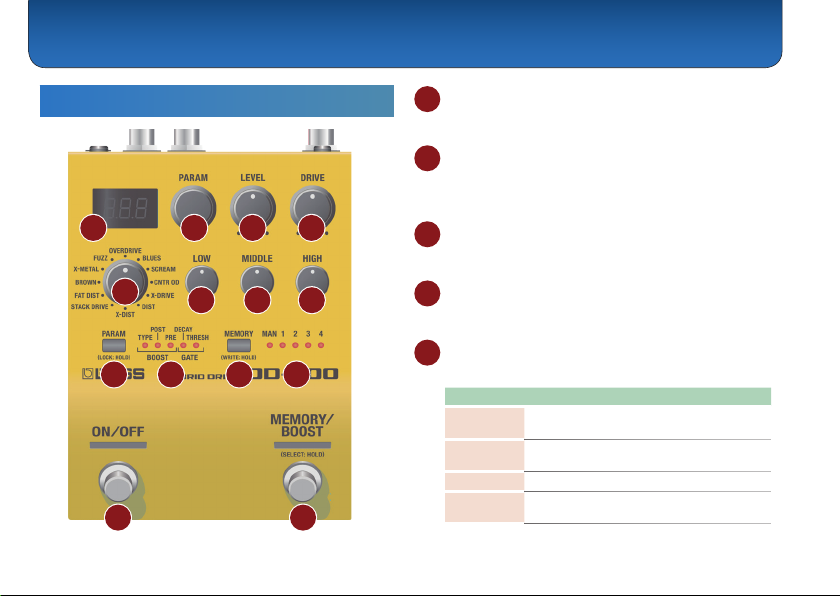
Panel Descriptions
Top Panel
1
2
3 4
2
5
6
7
9 10 11 12
13 14
1 Display
Shows the parameters and the values.
2 [PARAM] knob
Adjusts the parameter that is selected by the [PARAM]
button, or switches memories.
3 [LEVEL] knob
Adjusts the volume of the eect sound.
8
4 [DRIVE] knob
Adjusts the depth of distortion.
5 Mode knob
Selects the sound.
Mode Explanation
OVD
(OVERDRIVE)
BLS (BLUES)
SCR (SCREAM)
CNT (CNTR OD)
Uses an asymmetrical overdrive circuit to
produce sweet, mild distortion.
Providing distortion that faithfully reproduces
the nuances of your picking.
Sound similar to the Ibanez TS-808.
An eect that models the sound of the KLON
CENTAUR.
Page 3

Panel Descriptions
Mode Explanation
XDR (X-DRIVE)
DST (DIST)
XDS (X-DIST)
STK
(STACK DRIVE)
FAT (FAT DIST)
BRW (BROWN)
XMT (X-METAL)
FUZ (FUZZ)
Overdrive that uses MDP to provide ideal
distortion in each frequency region.
This gives a basic, traditional distortion sound.
Distortion that uses MDP to provide ideal
distortion in each frequency region.
Produces the sound of a large stack amp.
Drive settings provide a diverse variety of
distortion.
Distortion that provides a thick distortion
sound.
Lead sound with a distinct edge.
Core sound that uses MDP to preserve the
sound's denition even with extreme gain.
Sound similar to an Electro-Harmonix Big
Mu π.
6 [LOW] knob
Adjusts the sound level of the low-frequency range.
7 [MIDDLE] knob
Adjusts the sound level of middle-frequency range.
8 [HIGH] knob
Adjusts the sound level of the high-frequency range.
9 [PARAM] button
Selects the parameter that is adjusted by the [PARAM]
knob, or switches memories.
Parameter Explanation
BOOST TYPE
(BOOSTER TYPE)
MID: A booster with a distinctive
mid-range. A sound suitable for
soloing.
(CLEAN) : Raises the gain without
CLN
changing the guitar’s character.
(TREBLE) : A bright-sounding
TRB
booster.
(OVERDRIVE) : This models the
OVD
sound of the BOSS OD-1.
(BLUES) : This is a crunch sound of
BLS
the BOSS BD-2.
(SCREAM) : This models an Ibanez
SCR
TS-808.
(CNTR OD) : This models a KLON
CNT
CENTAUR.
(X-DRIVE) : This is an overdrive that
Xdr
uses MDP to obtain the distortion
that’s most appropriate in each pitch
range.
(DIST) : This models the sound of
DST
the BOSS DS-1.
3
Page 4

Panel Descriptions
Parameter Explanation
BOOST TYPE
(BOOSTER TYPE)
BOOST PRE
(BOOSTER PRE GAIN)
BOOST POST
(BOOSTER POST GAIN)
GATE DECAY
GATE THRESH
(GATE THRESHOLD)
4
XDS (X-DIST) : This is a distortion that
uses MDP to obtain the distortion
that’s most appropriate in each pitch
range.
(STACK DRIVE) : This models the
STK
sound of the BOSS ST-2.
(FAT DIST) : A distortion sound with
FAT
thick distortion.
(METAL ZONE) : This models the
MZN
sound of the BOSS MT-2.
(METAL CORE) : This models the
MCR
sound of the BOSS ML-2.
(FUZZ) : This models an Electro-
FUZ
Harmonix Big Mu π.
Adjusts the gain of the booster.
Adjusts the volume when boost is on.
Adjusts the time until the gate closes.
With smaller values, the gate closes
faster.
Adjusts the volume at which the gate
applies.
With larger values, the gate applies at
a higher volume.
You can also select a parameter or memory by pressing
the [PARAM] knob.
About the booster
As its main distortion, the OD-200 provides 12 dierent
types of sound.
The position of the booster connection and the
operations of the BOOSTER PRE GAIN, BOOSTER
POST GAIN, and LOW/MIDDLE/HIGH knobs will dier
depending on the STRUCTURE parameter.
When STRUCTURE is SERIES
The booster is placed before the main distortion.
Booster
Main
Booster
Guitar
&
Pre GAIN
&
distortion
&
Parameter Explanation
Adjusts the booster gain.
BOOST PRE
(BOOSTER PRE GAIN)
Increasing this value increases the
signal that is input to the main
distortion, making the distortion
stronger. The distortion of the booster
itself does not change.
Adjusts the volume when boost is on.
BOOST POST
(BOOSTER POST GAIN)
This let you raise (or lower) the
volume when using the booster to
increase the gain when transitioning
from backing to solo.
Post GAIN
Gate&Amp
&
Page 5

Panel Descriptions
Parameter Explanation
[LOW] [MIDDLE]
[HIGH] knobs
Adjust the tonal character of the main
distortion.
When STRUCTURE is PARALLEL
The booster and main distortion are placed in parallel.
Main
[LOW]
[MIDDLE]
[HIGH]
Adjusts the booster gain.
Depending on the type, the sound
will distort.
Adjusts the volume of the booster.
Adjust the tonal character of the
main distortion and the booster as
a whole.
Gate
Amp
Booster
Guitar
distortion
Parameter Explanation
BOOST PRE
(BOOSTER PRE GAIN)
BOOST POST
(BOOSTER POST GAIN)
[LOW] [MIDDLE]
[HIGH] knobs
Preventing accidental operation (panel lock)
By long-pressing the [PARAM] button, you can switch
between enabling (unlocking) or disabling (locking)
operation of the knobs and buttons.
If you attempt an operation while the unit is locked, the
display indicates “LCK.”
10 BOOST/GATE indicator
Indicates the parameter that can be adjusted by the
[PARAM] knob.
When the indicator is unlit, the knob selects memories.
Memory
MANUAL = “MAN”, memory 1–9 = “M-1”–“M-g”, memory
10–99 = “M10”–“Mgg”, memory 100–127 = “M.00”–“M.27”
11 [MEMORY] button
Switches or saves memories (MANUAL, 1–127) (p. 8).
The memory is switched each time you press the
[MEMORY] button. You can also switch memories by
holding down the [MEMORY] button and turning the
[PARAM] knob.
12 MEMORY indicator
Indicates the currently selected memory.
If a memory 5–127 is selected, the indicator is unlit.
13 [ON/OFF] switch
Turns the eect on/o.
5
Page 6

Panel Descriptions
14 [MEMORY/BOOST] switch
Switches memories (p. 8).
Long-press the [MEMORY/BOOST] switch to turn the
booster on/o.
MEMO
The function of the footswitch can be changed by
“MFC”
(MEMORY SWITCH FUNCTION).
Rear Panel (Connecting Your Equipment)
* To prevent malfunction and equipment failure, always turn down the
volume, and turn o all the units before making any connections.
D
A B
6
C
A INPUT jack
Connect your guitar, bass, or eect unit here.
Turning On/O the Power
The INPUT jack also operates as the power switch. The
power turns on when you insert a plug into the INPUT
jack.
When powering up
Power-up equipment such as your guitar amp last.
When powering down
Power-down equipment such as your guitar amp rst.
* Before turning the unit on/o, always be sure to turn the volume
down. Even with the volume turned down, you might hear some
sound when switching the unit on/o. However, this is normal and
does not indicate a malfunction.
B OUTPUT jack
Connect this jack to your amp or eector.
C CTL 1, 2/EXP jack
Using the jack as CTL 1, 2
You can connect a footswitch (sold separately: FS-5U,
FS-6, FS-7) and use it to switch the booster ON/OFF or
switch memories (p. 9).
Page 7

Panel Descriptions
Using the jack as EXP
You can connect an expression pedal (sold separately:
EV-30, Roland EV-5, etc.) and use it to control the
amount of boost or the volume of the eect sound
(p. 11).
* Use only the specied expression pedal. By connecting any other
expression pedals, you risk causing malfunction and/or damage
to the unit.
D DC IN jack
An AC adaptor (sold separately: PSA-S series) can be
connected to this jack.
* Use only the specied AC adaptor (sold separately: PSA-S series)
and plug it into an AC outlet of the correct voltage.
* If the AC adaptor is connected while power is on, the power supply
is drawn from the AC adaptor.
Side Panel (Connecting Your Equipment)
F
E
MIDI jacks
E
Use a TRS/MIDI connecting cable (sold separately:
BMIDI-5-35) to connect an external MIDI device. You can
use an external MIDI device to switch the memories of
this unit.
* Do not connect an audio device here. Doing so will cause
malfunctions.
F USB port
Connect your computer using a commercially available
USB cable that supports USB 2.0.
* Do not use a micro USB cable that is designed only for charging a
device. Charge-only cables cannot transmit data.
* This is used only for program updates.
7
Page 8

Saving and Switching Memories
Saving to Memory
Here's how to save eect settings that you edited.
1. Long-press the [MEMORY] button.
The display indicates “Wrt.”
2. Turn the [PARAM] knob to select the save-
destination (MAN, 1–127).
You can also select the save-destination by pressing
the [MEMORY] button.
If you decide to cancel, press the [PARAM] button.
3. Long-press the [MEMORY] button to conrm
the save-destination.
The memory is saved.
* If you save to MAN, the settings of the panel are applied as the
values for MODE, DRIVE, LEVEL, LOW, MIDDLE, and HIGH.
8
Switching Memories
Here’s how to recall a saved memory.
1. Press the [MEMORY] button to select a
memory.
Each time you press the button, you cycle through
the memories in the order of “MAN (manual) 0 1
0 2 0 3 04 ...1270 MAN...”
You can also switch memories by holding down the
[MEMORY] button and turning the [PARAM] knob.
* The MEMORY indicator is unlit if a memory 5–127 is selected.
MEMO
You can specify the memory switching range by editing
the
ETF (EXTENT FROM)
What is “MAN” (manual)?
This unit normally applies the eect according to the
settings that are saved in memory, but if you select
MAN (manual) the eect is applied according to the
positions of the panel knobs. Even in this case, the
booster and gate settings recall the settings that are
written to MAN (this can be changed).
and
ETT (EXTENT TO)
settings (p. 11).
Page 9

Overall Settings (Menu)
Basic Operation
1. Press the [PARAM] button and [MEMORY]
button simultaneously.
You enter menu mode.
2. Turn the [PARAM] knob to select a parameter,
and then press the [PARAM] knob.
The value is displayed.
3. Turn the [PARAM] knob to edit the value.
4. Press the [PARAM] knob.
5. Press the [PARAM] button and [MEMORY]
button simultaneously.
You exit menu mode.
Assigning functions to external pedals
You can connect a footswitch (sold separately: FS-5U, FS-6, FS-7) to
the CTL 1, 2/EXP jack, and use it to switch the booster on/o or to
change memories.
Use the menu items “C1F” or “C2F” to make these settings (p. 10).
FS-5U FS-6, FS-7
CTL 1
CTL 2 CTL 1
FS-5U
FS-5U×2
CTL 2 CTL 1
CTL 2
CTL 1
FS-6, FS-7
9
Page 10

Overall Settings (Menu)
MEMORYMEMORY
MEMORYMEMORY
MEMORYMEMORY
MEMORYMEMORY
MEMORYMEMORY
MEMORYMEMORY
Menu Parameter List
About the
5 Can be set and saved for each memory by the “Saving to Memory” (p.
8) operation. If you do not perform this operation, the settings are lost
when you switch memories.
5 Can be set and saved for each memory if the preference (SWP/MEP/C1P/
C2P/EPP) is set to MEM (MEMORY). To save, refer to “Saving to Memory”
(p. 8).
If set to SYS (SYSTEM), the settings common to the unit are used. Function
settings are saved automatically.
Parameter Explanation
STR
(STRUCTURE)
10
mark
Selects how the main distortion and the
booster are connected.
(SERIES): Connected in the order of
SER
booster & main distortion.
(PARALLEL): The booster and the main
PRL
distortion are connected in parallel.
Parameter Explanation
Specify the functions of the [ON/OFF]
switch, [MEMORY/BOOST] switch, and
SWF
(ON/OFF SWITCH
FUNCTION)
MFC
(MEMORY SWITCH
FUNCTION)
C1F
(CTL1 FUNCTION)
C2F
(CTL2 FUNCTION)
footswitches connected to the CTL 1, 2/
EXP jack.
* The functions that can be assigned dier
depending on the switch.
oFF: No operation.
SW
(ON/OFF SWITCH) : Turns the eect on/o.
BST
(BOOST) :Turns the booster on/o.
MAn
(MANUAL) : Selects manual.
M-1
(MEMORY 1) –M-g (MEMORY 9): Selects memory
1–9.
M10
(MEMORY 10) –Mgg (MEMORY 99): Selects
memory 10–99.
M.00
(MEMORY 100) –M.27 (MEMORY 127): Selects
memory 100–127.
MUP
(MEMORY UP) : Increments the memory
number according to the MEMORY EXTENT
setting. Long-press the switch to turn the booster
on/o.
Mdn
(MEMORY DOWN) : Decrements the memory
number according to the MEMORY EXTENT
setting. Long-press the switch to turn the booster
on/o.
MUP.
(MEMORY UP, ON/OFF) : Increments the memory
number according to the MEMORY EXTENT
setting. Long-press the switch to turn the eect
on/o.
MDN.
(MEMORY DOWN, ON/OFF) : Decrements the
memory number according to the MEMORY
EXTENT setting. Long-press the switch to turn the
eect on/o.
Page 11

Overall Settings (Menu)
MEMORYMEMORY
MEMORYMEMORY
MEMORYMEMORY
Parameter Explanation
EPF
(EXPRESSION FUNCTION)
EPN
(EXPRESSION MIN)
EPM
(EXPRESSION MAX)
Species the function of an expression
pedal connected to the CTL 1, 2/EXP jack.
oFF: No operation.
(DRIVE) : The same operation as the
DRV
[DRIVE] knob.
(LEVEL) : The same operation as the
LVL
[LEVEL] knob.
(LOW) : The same operation as the
LO
[LOW] knob.
(MIDDLE) : The same operation as the
MID
[MIDDLE] knob.
(HIGH) : The same operation as the
HI
[HIGH] knob.
(BOOSTER PRE LEVEL) : Adjusts the
PRE
BOOSTER PRE LEVEL parameter.
(BOOSTER POST LEVEL) : Adjusts the
PST
BOOSTER POST LEVEL parameter.
Species the variable range of the
parameter controlled by EXPRESSION
FUNCTION. The variable range diers
depending on the parameter.
Parameter Explanation
SWP
(ON/OFF SWITCH FUNCTION
PREFERENCE)
MEP
(MEMORY SWITCH
FUNCTION PREFERENCE)
C1P
(CTL1 FUNCTION
PREFERENCE)
C2P
(CTL2 FUNCTION
PREFERENCE)
EPP
(EXPRESSION FUNCTION
PREFERENCE)
ETF (EXTENT FROM)
ETT (EXTENT TO)
MEM (MEM) : The setting in memory is used.
(SYS) : The controller’s function is xed
SYS
regardless of memory.
Specify the memory switching range
(MEMORY EXTENT FROM–TO).
(MANUAL), M-1 (MEMORY 1) –M.27
MAN
(MEMORY 127)
Species the MIDI receive channel.
RCH
(MIDI RECEIVE CHANNEL)
If this is “oFF,” MIDI messages are not
received.
1–16, oFF
Species the MIDI transmit channel.
If this is “oFF,” MIDI messages are not
TCH
(MIDI TRANSMIT CHANNEL)
transmitted.
If this is RECEIVE, the same setting as the
receive channel is used.
1–16, RCv
(RECEIVE), oFF
11
Page 12

Overall Settings (Menu)
Parameter Explanation
PIN (PC IN)
POT (PC OUT)
CCI (CC IN)
CCO (CC OUT)
Species whether program changes are
received (on) or not received (oFF).
Species whether program changes
are transmitted (on) or not transmitted
(oFF).
Correspondence between memories
and program numbers
Memory Program number
MAN
MEMORY 1–127
Species whether control changes are
received (on) or not received (oFF).
By receiving CC messages, this unit
lets you use MIDI to control the same
operations as a knob or footswitch.
Species whether control changes are
transmitted (on) or not transmitted
(oFF).
12
1
2–128
Parameter Explanation
DRC (DRIVE CC)
LVC (LEVEL CC)
LOC (LOW CC)
MDC (MIDDLE CC)
HIC (HIGH CC)
PRC
(BOOSTER PRE LEVEL CC)
PSC
(BOOSTER POST LEVEL CC)
SWC
(ON/OFF SWITCH CC)
BSC
(BOOSTER ON/OFF CC)
MEC
(MEMORY/BOOST SWITCH CC)
Specify the controller number
corresponding to each item.
oFF, 1–31, 64–95
C1C (CTL1 CC)
C2C (CTL2 CC)
EPC (EXPRESSION CC)
EFC
(EFFECT ON/OFF CC)
Page 13

Overall Settings (Menu)
Parameter Explanation
MTH (MIDI THRU)
P1–Pg
(P1–P9)
P10–Pgg
(P10–P99)
P.00–P.28
(P100–P128)
Species whether MIDI messages received
at the MIDI IN connector are retransmitted
without change from the MIDI OUT
connector (on) or are not retransmitted
(oFF).
Specify the memory corresponding to the
received program number. Bank select is
ignored (received regardless).
If this is “OFF,” the eect turns o.
OFF, MAN, M-1–M.27
13
Page 14

Appendix
Returning to the Factory Settings (Factory Reset)
Here’s how to return the OD-200 to its factory-set state.
1. While holding down the [ON/OFF] switch and
[MEMORY/BOOST] switch, turn on the power
(insert a plug into the INPUT jack).
The display indicates “FCt.”
2. Press the [MEMORY/BOOST] switch.
The display indicates “Sur.”
If you decide to cancel, press the [MEMORY] button.
3. Press the [MEMORY/BOOST] switch.
The factory reset is executed.
4. When the display indicates “FIn,” turn the
power o and on again.
14
Installing Batteries
Insert the batteries as shown below, being careful to
orient the batteries correctly.
* Batteries should always be installed or
replaced before connecting any other
devices. This way, you can prevent
malfunction and damage.
* If operating this unit on batteries, please
use alkaline batteries.
* Even if batteries are installed, the unit
will turn o if you connect or disconnect
the power cord from the AC outlet while
the unit is turned on, or if you connect or
disconnect the AC adaptor from the unit.
When this occurs, unsaved data may be
lost. You must turn o the power before
you connect or disconnect the power cord
or AC adaptor.
* When turning the unit over, be careful so
as to protect the buttons and knobs from damage. Also, handle the unit
carefully; do not drop it.
* If you handle batteries improperly, you risk explosion and uid leakage.
Make sure that you carefully observe all of the items related to batteries
that are listed in “USING THE UNIT SAFELY” and “IMPORTANT NOTES”
(leaet “USING THE UNIT SAFELY”).
* “Lo” will appear on the display if the batteries are low. Replace them with
new ones.
Page 15

Appendix
Attaching the Rubber Feet
You can attach the rubber feet (included) if necessary.
Attach them in the locations shown in the illustration.
* Using the unit without rubber feet may damage the oor.
Main Specications
BOSS OD-200: HYBRID DRIVE
Power Supply
Current Draw
Expected Battery
Life Under
Continuous Use
Dimensions
Weight
Accessories
Options
* This document explains the specications of the product at the time that
the document was issued. For the latest information, refer to the Roland
website.
Alkaline battery (AA, LR6) x 3,
AC adaptor (sold separately)
220 mA
Alkaline: Approx. 6 Hours
* These gures will vary depending on the actual
conditions of use.
101 (W) x 138 (D) x 63 (H) mm / 4 ( W) x 5-7/16 (D) x 2-1/2
(H) inches
101 (W) x 138 (D) x 65 (H) mm / 4 ( W) x 5-7/16 (D) x 2-9/16
(H) inches (including rubber foot)
670 g / 1 lb 8 oz (including batteries)
Owner’s Manual
Leaet “USING THE UNIT SAFELY”
Alkaline battery (AA, LR6) x 3
Rubber foot x 4
AC adaptor: PSA-S series
Footswitch: FS-5U
Dual footswitch: FS-6, FS-7
Expression pedal: FV-500H, FV-500L, EV-30, Roland EV-5
MIDI/TRS connecting cable: BMIDI-5-35
15
Page 16

USING THE UNIT SAFELY/IMPORTANT NOTES
CAUTION
Keep small items out of the reach of children
To prevent accidental ingestion of the parts
listed below, always keep them out of the reach
of small children.
• Included Parts
Rubber feet (p. 15)
16
Repairs and Data
• Before sending the unit away for repairs, be sure to
make a backup of the data stored within it; or you
may prefer to write down the needed information.
Although we will do our utmost to preserve the data
stored in your unit when we carry out repairs, in some
cases, such as when the memory section is physically
damaged, restoration of the stored content may be
impossible. Roland assumes no liability concerning the
restoration of any stored content that has been lost.
Additional Precautions
• Any data stored within the unit can be lost as the
result of equipment failure, incorrect operation, etc. To
protect yourself against the irretrievable loss of data,
try to make a habit of creating regular backups of the
data you’ve stored in the unit.
• Roland assumes no liability concerning the restoration
of any stored content that has been lost.
• Do not use connection cables that contain a built-in
resistor.
Page 17

Intellectual Property Right
• This product includes third party open source software.
Copyright (c) 2009-2017 ARM Limited. All rights reserved.
Licensed under the Apache License, Version 2.0 (the
“License”); You may obtain a copy of the License at
http://www.apache.org/licenses/LICENSE-2.0
• Roland, BOSS are either registered trademarks or
trademarks of Roland Corporation in the United States
and/or other countries.
• Company names and product names appearing in this
document are registered trademarks or trademarks of
their respective owners.
• In this manual, company names and product names
of the respective owners are used because it is the
most practical way of describing the sounds that are
emulated using DSP technology.
USING THE UNIT SAFELY/IMPORTANT NOTES
17
Page 18

 Loading...