

Page 1

6.2010
Page 2
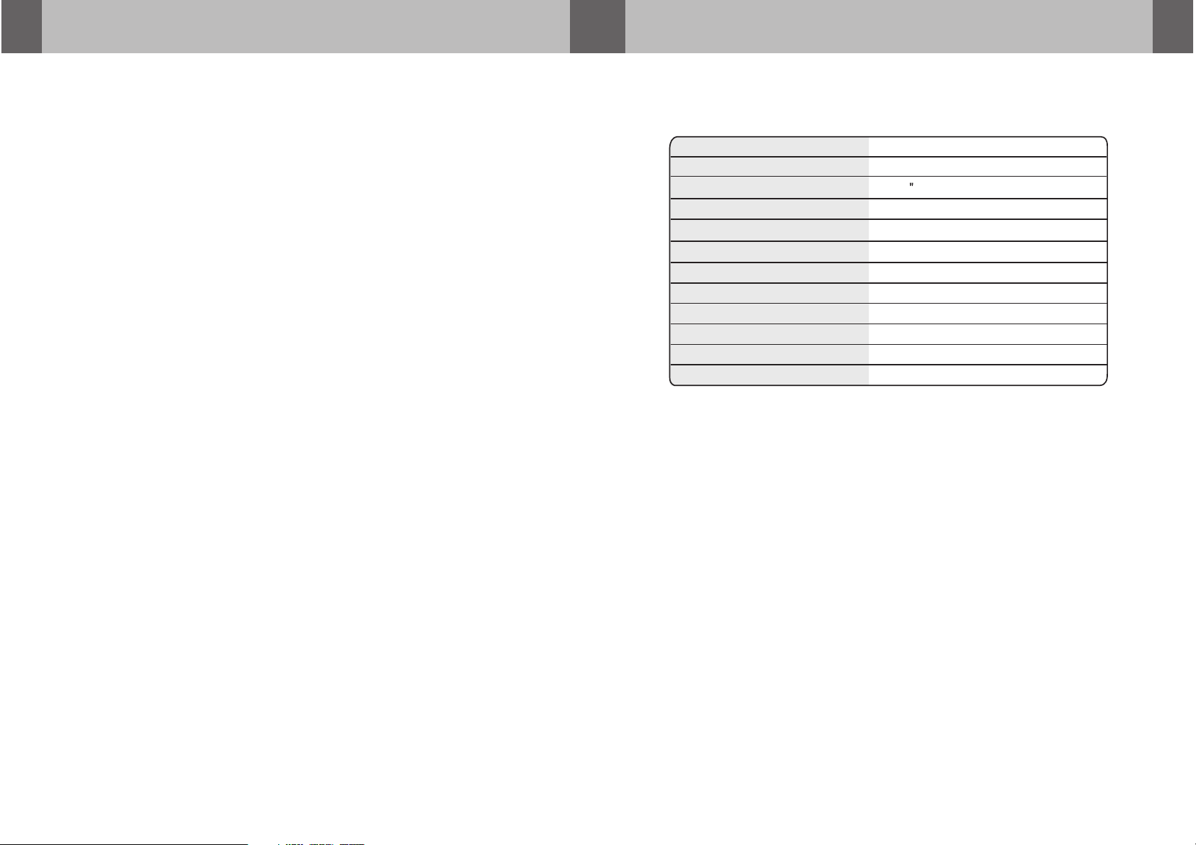
SPECIFICATIONS
Power Requirements
Power Consumption
Screen Size
Screen Format
Resolution Pixel
A/V Inputs
Dimensions
IR Power Requirements
IR Power Consumption
IR Transmitter Frequency
LCD Panel Type
Compatible video standard
Note : This eq uip ment has been tes ted and found to co mpl y with the lim its f or
a Class A dig ita l device, pu rsu ant to part 15 o f the F CC Rules. These limi ts
are des ign ed to provid e rea sonable pr ote ction against h armful interf ere nce
when th e equ ipment is op era ted in a comme rci al environmen t.
This eq uip ment gener ate s, uses, and c an ra diate radio fre quency energy a nd,
if not in sta lled and use d in ac cordance w ith t he instructio n manual, may cau se
harmf ul in terferen ce to r adio commu nic ations. Opera tion of this equi pme nt in
a resid ent ial area is li kel y to cause har mfu l interferenc e in which case the u ser
will be r equ ired to corr ect t he interfe ren ce at his own expen se.
D C 1 2 V
9 W
1 0 . 4 T F T-LCD
4 : 3
11 52 * 2 3 4
AV 1 / V 2 I n p u t s
( L ) 1 2 . 5 (W)12.3 ( H ) 2 . 2 i n c h× ×
D C 1 2 V
3 W
R i g h t 2 . 8 M H z L e f t 2 . 3 M H z
A c t i v e M a t r i x T F T
N T S C / PA L a u t o s e l e c t
10
Page 3

Releasing the Monitor
Push t he o p en b utt o n ( l o cat e d on t he f ront e dge o f t h e s c ree n h ousi n g)
and lowe r t he m oni t o r t o t h e d e s ired a ngle . You c a n a l so a dju s t t h e
swiv e l a n gle.
,
USER S MANUALMONITOR OPERATION
Please read thi s User,s Manual in detai l and use the set properly.
PRECAUTIONS 4
… … … … … … … … … … … … … … … … … … …
PU SH BU TTON
How to use the monitor
1. Connect the mon itor to t he exte rnal devices.
2. Press the POWER b utton o n eithe r the remote control or the unit onc e to turn
the power on.
Press the same POW ER butt on to tur n the power off.
POWER
INSTALLATION 5
FEATURES AND CONTROLS
A/V AND POWER CONNECTIONS 8
MONITOR OPERATION
Releasing the Monitor
How to watch the Monitor
SPECIFICATIONS 10
… … … … … … … … … … … … … … … … … …
… … … … … … … … … … … …
… … … … … … … … … … …
… … … … … … … … … … … … … … …
… … … … … … … … … … … … … …
… … … … … … … … …
…
… … … … ……………………………………
6
9
9
9
POWER
UNIT
3. Turn on the extern al devi ces and view.
REMOTE CONT ROL LER
9
2
Page 4

PRECAUTIONS
A/V AND POWER CONNECTIONS
Please re ad and obse rve all warnings a nd instructions in this own er s manual
,
and those m arked on the unit. Retain thi s booklet for futu re refere nce.
There are two kinds of al arm symbols as follow s:
The lig htning fla sh with arro whead symb ol within an equi lateral
WARNIN G
trian gle is inten ded to alert t he user to the p resence of
dange rous volta ge w ithin the pr oduct s enclosu re that may be
" "
of suff icient mag nitude to co nstitute a r isk of elect ric s hock to
peopl e.
,
The exc lam ation poin t wit hin an equilate ral triangle is i nte nded
to aler t the u ser to the pre sen ce of important o perating and
maint ena nce (servi cin g) instructio ns in the literat ure a ccompany ing
CAUTI ON
the pro duc t.
WARNING
Installat ion o f all TV monitor s
P
O
W
E
R
A
V
MEN
U
must be out of th e dri ver s
field of visi on.
Do not try and se rvi ce th ese
products yo urs elf . See k only
a qualified s erv ice c ent er or
factory ser vic e cen ter.
Be caref ul not t o dro p or app ly
pressu re to th e fro nt pan el of
your vid eo mon ito r. If the s cre en
cracks d ue to mi sus e, you r war rant y
will be vo id!
or wipe the pro duc ts wi th a to wel. Do not
operate the e qui pme nt un til all liquids hav e
either evap ora ted o r you h ave had the monitor
inspected a t a ser vic e cen ter by a qualified
technicia n, Se ver e har m or danger can occur.
Do not mount th e pro duc t whe re
it will obstr uct t he de plo yment of
the airbag or i n an ar ea wh ere i t
would affec t the v ehicular contro l.
Also be caref ul to a voi d mou nting
the product w her e it ca n bec ome
hazardous d uri ng su dde n stops or
in the event of a n acc ide nt.
Use extra cau tio n wit h any l iquids
in your car. If yo u or yo ur ch ild
spills any li qui d on th ese p roducts,
pull your veh icl e to th e roa dside
and turn the ke y off t o disconnect
+ 12 V DC Batt ery
Cha ssi s Grou nd
ACC
YEL LOW
BLACK
RED
FUSE
Car dome l amp
WHI TE
Whi te AUDIO( L)
Red A UDIO (R)
Yellow VI DEO
AV Input
(AV 1)
Video2 Inp ut
Yellow Vide o
MENU
R
DVD P LAYER
CAM CORDE R
VIDE O
GAM E
Use only a damp c lot h to cl ean
the screen an d use o nly p uri fied
water on the cl oth . Wring out all
excess wate r pri or to w ipi ng the
screen. Do no t use a ny cl ean ers
or chemical s to cl ean t he sc reen.
In most cases a d ry cl oth w ill d o!
3
Pos itive Neg ative
Trig ger Doo r Tri gger D oor
Swi tch S witc h
Dome Lig ht Tri gger
8
Page 5

FEATURES AND CONTROLS
PRECAUTIONS
CAUTION
POWER Bu tto n
Left Dom e Lig ht Button
A/V sele ct
Button
MENU But ton
Right Do me Li ght Butto n
Up/Dow n but ton
Interface Switch Function
Power Power O N/O FF
AV ignal elect:
Menu Press t his b utt on for OSD menu.
S S
:
And select m enu option
:+
Increase c urrent o pti on v alu e.
-::
Decrease c urrent o pti on va lue .
Quali ty in stallati ons a re best
perfo rme d by qualifi ed an d
certi fie d installe rs.
,
Don t tou ch th e unit if ther e is
a flash o f lig htning. It m ay
recei ve an e lectric sh ock .
Do not co ver h eater duct s or ve nts.
This ma y cau se a fire or an el ect ric
shock .
Wat ching the monit or fo r an
exten ded p eriod of tim e
with th e eng ine turned o ff
may dep let e the vehicl e s
batte ry.
This pr odu ct is design ed fo r
opera tio n with a 12 Volt DC ,
negat ive g round vehi cle . It
is not su ita ble for oper ati on
under o the r conditio ns or
volta ges .
Check Point
1. The op erati ng temperature of this product i s limit ed to 14 F~ 140 F
(-10 C~60 C).
Your vehicle can reach temper ature s up to 100 C i n the summertime.
,
POWER K EY
- KEY
LCD MONITOR
REMOTE CONTROL UNIT
7
AV1/V2 KEY
MENU KE Y
+ KEY
2. When your vehic le is ext remely hot or cold you must allow ti me for yo ur air
conditioner or h eater t o cool or heat the vehicle and for ope ratin g tempe ratures
to return to norma l opera ting ranges. Your monitor w ill ret urn to it s normal
functions when t hese op erating ranges are achieved.
3. Optimum pictu re qual ity is ac hieved when you are direc tly in fr ont of th e monitor
(+/-45 degrees ).
4
Page 6

INSTALLATION FEATURES AND CONTROLS
1. Open the packag ing and c heck that these parts are presen t.
Dome light
INSTAL LATION PLATE
2. Connect the ext ernal c omponents to the RCA cable or AV output.
(Refer to the conn ectio n diagram on page 8)
3. Match the posit ion of in stall ation bracket and
4. Secure the unit i n place w ith the s upplied
screw B.
UNIT
installation p late wi th screw A.
SCREW A SCREW B
Infrared Transmitter
Monitor
(Front)
5
6
 Loading...