

Page 1

CONTENTS
SAFETY INFORMATION ...................................................................................................................2
ELECTROSTATIC DISCHARGE SENSITIVE (ESDS) DEVICE HANDLING .................................. 2
WARRANTY........................................................................................................................................2
ELECTRICAL SPECIFICATIONS...................................................................................................... 3
MECHANICAL SPECIFICATIONS.....................................................................................................4
PRODUCT DESCRIPTION ...............................................................................................................4
PART LIST NOTES ........................................................................................................................... 4
PACKAGING PART LIST .................................................................................................................. 5
Figure 1. Lifestyle
PACKAGING PART LIST .................................................................................................................. 6
Figure 2. Lifestyle
MAIN PART LIST ...............................................................................................................................7
Figure 3. Lifestyle
MAIN PART LIST ...............................................................................................................................8
Figure 4. Lifestyle
ELECTRICAL PART LIST .................................................................................................................9
SA-2 DISASSEMBLY PROCEDURES ............................................................................................ 17
SA-3 DISASSEMBLY PROCEDURES ............................................................................................ 19
TEST SET-UP ................................................................................................................................... 22
TEST PROCEDURES ..................................................................................................................... 23
Lifestyle
Lifestyle
®
SA-2 & SA-3 Amplifier PCB Rev. 0 Topside Component and Etch Layout Diagram..........24
®
SA-2 & SA-3 Amplifier PCB Rev. 0 SMD Etch and Component Layout Diagram ..............25
®
SA-2 Packaging View ......................................................................................... 5
®
SA-3 Packaging View .........................................................................................6
®
SA-2 Exploded View ...........................................................................................7
®
SA-3 Exploded View ........................................................................................... 8
CAUTION: The Bose® Lifestyle® SA-2 & SA-3 amplifiers contain
no user-serviceable parts. To prevent warranty infractions,
refer servicing to warranty service stations or factory service.
PROPRIETARY INFORMATION
THIS DOCUMENT CONTAINS PROPRIETARY INFORMATION OF
BOSE CORPORATION WHICH IS BEING FURNISHED ONLY FOR
THE PURPOSE OF SERVICING THE IDENTIFIED BOSE PRODUCT
BY AN AUTHORIZED BOSE SERVICE CENTER OR OWNER OF THE
BOSE PRODUCT, AND SHALL NOT BE REPRODUCED OR USED
FOR ANY OTHER PURPOSE.
1
Page 2

SAFETY INFORMATION
1. Parts that have special safety characteristics are identified by the symbol on schematics
or by special notes on the parts list. Use only replacement parts that have critical characteristics
recommended by the manufacturer.
2. Make leakage current or resistance measurements to determine that exposed parts are
acceptably insulated from the supply circuit before returning the unit to the customer. Refer to
UL6500 clause 9.1.1. Use the following checks to perform these measurements:
A. Leakage Current Hot Check-With the unit completely reassembled, plug the AC line cord
directly into a 120V AC outlet. (Do not use an isolation transformer during this test.) Use a leakage current tester or a metering system that complies with American National Standards Institute
(ANSI) C101.1 "Leakage Current for Appliances" and Underwriters Laboratories (UL) 6500. With
the unit AC switch first in the ON position and then in OFF position, measure from a known earth
ground (metal waterpipe, conduit, etc.) to all exposed metal parts of the unit (antennas, handle
bracket, metal cabinet, screwheads, metallic overlays, control shafts, etc.), especially any
exposed metal parts that offer an electrical return path to the chassis. Any current measured
must not exceed 0.5 milliamp. Reverse the unit power cord plug in the outlet and repeat test.
ANY MEASUREMENTS NOT WITHIN THE LIMITS SPECIFIED HEREIN INDICATE A POTENTIAL SHOCK HAZARD THAT MUST BE ELIMINATED BEFORE RETURNING THE UNIT TO THE
CUSTOMER.
B. Insulation Resistance Test Cold Check-(1) Unplug the power supply and connect a jumper
wire between the two prongs of the plug. (2) Turn on the power switch of the unit. (3) Measure
the resistance with an ohmmeter between the jumpered AC plug and each exposed metallic
cabinet part on the unit. When the exposed metallic part has a return path to the chassis, the
reading should be between 1 and 5.2 Megohms. When there is no return path to the chassis, the
reading must be "infinite". If it is not within the limits specified, there is the possibility of a shock
hazard, and the unit must be repaired and rechecked before it is returned to the customer.
ELECTROSTATIC DISCHARGE SENSITIVE (ESDS)
DEVICE HANDLING
This unit contains ESDS devices. We recommend the following precautions when repairing,
replacing or transporting ESDS devices:
• Perform work at an electrically grounded work station.
• Wear wrist straps that connect to the station or heel straps that connect to conductive
floor mats.
• Avoid touching the leads or contacts of ESDS devices or PC boards even if properly
grounded. Handle boards by the edges only.
• Transport or store ESDS devices in ESD protective bags, bins, or totes. Do not insert
unprotected devices into materials such as plastic, polystyrene foam, clear plastic bags,
bubble wrap or plastic trays.
WARRANTY
The Bose® Lifestyle® SA-2 and SA-3 amplifiers are covered by a limited one year transferable warranty.
2
Page 3
ELECTRICAL SPECIFICATIONS
Voltage Variations: US: 120 Vrms
International: 220-240 Vrms
Maximum Power: SA-2: 40 Watts into 6 Ohms @ <0.1% THD
20 Hz to 10kHz
SA-3: 100 Watts into 6 Ohms @ < 0.2%THD
20 Hz to 10 kHz
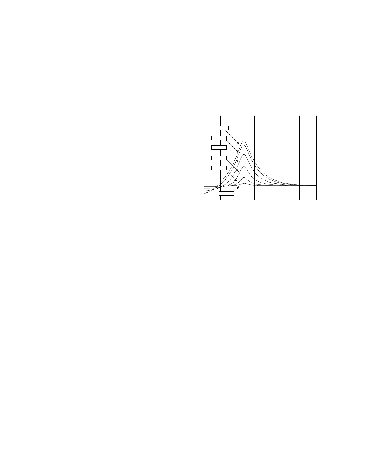
Frequency Response: 20 Hz - 20 kHz,+/- 0.5 dB (at full volume)
Dynamic Equalization:
25
<40 dB SPL
20
R
E
S
P
O
N
S
E
:
:
D
B
50 dB SPL
15
60 dB SPL
10
70 dB SPL
80 dB SPL
5
0
-5
1E 1 1E 2 1E 3
90 dB SPL
FREQUENCY--HERTZ
Voltage Gain (at 1 kHz): SA-2: 34.2 dB +/- 0.5 dB
SA-3: 38.2 dB +/- 0.5 dB
Input Impedance at (at 1 kHz): 10 k +/- 1 Ohms
Signal to Noise Ratio: 92 dB
Input Sensitivity: 0.3 Vrms at full volume produces rated
output power
Compressor: Range: 18 dB (minimum)
Attack Time: 1 dB/ 700uS
Release Time: 1 dB/10 mS
Distortion: <2%THD @100 Hz, 18 dB into compression
Turn-On Delay (to unmute): 1 second maximum at initial turn-on
0.2 second maximum from standby
Volume Control Range: 0 to -80 dB in 1 dB steps
Output DC offset: < 20 mVdc
Channel Balance: +/- 0.5 dB
Output Short-Curcuit Duration: Infinite (with no damage)
Standby Power Consumption: < 1 Watts (real power) at rated line voltage
3
Page 4

MECHANICAL SPECIFICATIONS
Quiescent ON Power Consumption: SA-2: < 10 Watts
SA-3: < 15 Watts
Maximum Power Consumption: SA-2: < 220 Watts
SA-3: < 400 Watts
Size: SA-2: 3½”H x 14 1/8”W x 5½”D
(8.9cm x 35.9cm x 14cm)
SA-3: 4¼”H x 14 1/8”W x 5½”D
(11.4cm x 35.9cm x 14cm)
Weight; shipping: SA-2: 7.6 lbs. (3.4 kg)
SA-3: 11.1 lbs. (5 kg)
Enclosure Material: Housing: Die cast aluminum (A360)
Bottom: 20 Ga. steel plate
Finish: Textured black powdercoat
Controls: Power switch (International version only)
Voltage select switch (Dual Voltage version
only)
PRODUCT DESCRIPTION
The SA-2 Amplifier is a 2 x 40W stereo audio amplifier intended to power Bose® 161™, 191, 201®,
or AM-3 indoor “zone 2” loudspeakers. It is the next generation version of SA-1, updated to work
with the next generation media centers. It recognizes and responds to smart speaker II protocol
commands. The SA-3 Amplifier is a 2 x 100W stereo audio amplifier intended to power Bose high
SPL passive loudspeakers which can be used in second zone applications, specifically, 251
FS-51 (outdoor), AM-5
tional features: local audio source input and mono/stereo switch. The SA-3 recognizes and responds to smart speaker I (CD-5, CD-20, MRI) or II (AV18 and AV48) protocol commands.
®
or 301® (indoor). SA-3 is the higher power version of SA-2, with two addi-
®
or
PART LIST NOTES
1. This part is not normally available from Customer Service. Approval from the Field Service
Manager is required before ordering.
2. The individual parts located on the PCBs are listed in the Electrical Part List.
3. This part is critical for safety purposes. Failure to use a substitute replacement with the
same safety characteristics as the recommended replacement part might create shock, fire
and/or other hazards.
4
Page 5
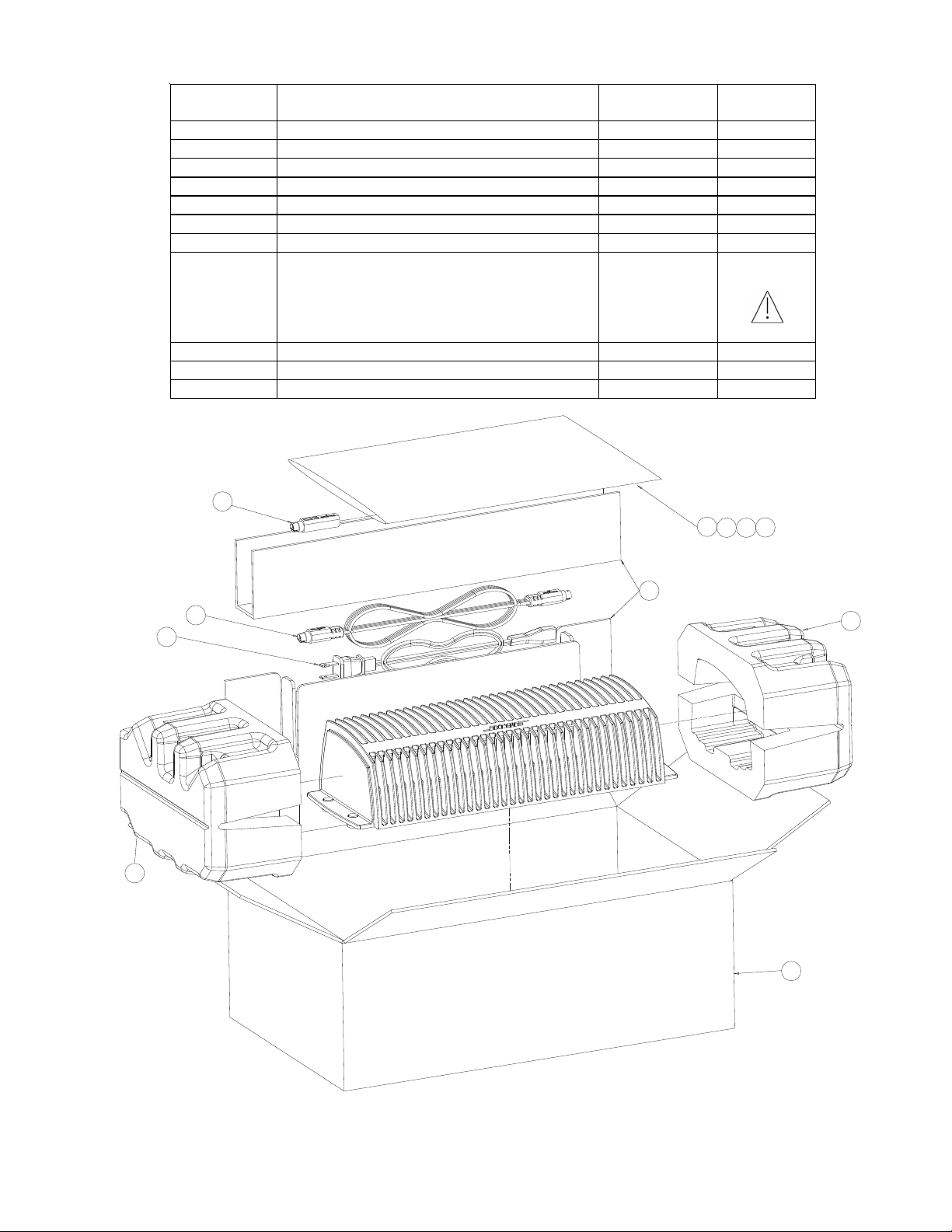
PACKAGING PART LIST
Reference
Designator
1 8 TO 9 PIN DIN ADAPTER 273263
2 BAG, POLY, 14 3/8X9 7/8X2 MIL 103351
3 REGISTRATION & WARRANTY CARD 262933
4 SHEET, SAFETY 275072
5 OWNERS MANUAL, 3 LANGUAGE 275071
6 PACKING, INSERT 275424
7 CABLE, DIN-9, 20FT 272902-220
8 LINE CORD, DETACH, BLK
US/DUAL VOLTAGE
220-240V, EURO
240V, UK
240V, AUS
9 PACKING, END CAP, EPS 275423
10 CARTON, RSC 275422
-- BAG, POLY, 12X20X4 MIL 197405
1
Description Part Number Note
198603-001
148203
134725
134726
2
3
4
3
5
6
7
9
8
9
10
Figure 1. Lifestyle® SA-2 Packaging View
5
Page 6
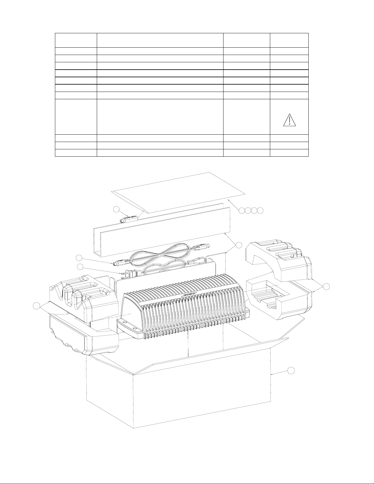
PACKAGING PART LIST
Reference
Designator
1 8 TO 9 PIN DIN ADAPTER 273263
2 BAG, POLY, 14 3/8X9 7/8X2 MIL 103351
3 REGISTRATION & WARRANTY CARD 262933
4 SHEET, SAFETY 275072
5 OWNERS MANUAL, 3 LANGUAGE 275071
6 PACKING, INSERT 275424
7 CABLE, DIN-9, 20FT 272902-220
8 LINE CORD, DETACH, BLK
US/DUAL VOLTAGE
220-240V, EURO
240V, UK
240V, AUS
9 PACKING, END CAP, EPS 275423
10 CARTON, RSC 276289
-- BAG, POLY, 12X20X4 MIL 197405
Description Part Number Note
198603-001
148203
134725
134726
3
1
7
8
9
4
5
2
3
6
9
10
Figure 2. Lifestyle® SA- 3 Packaging View
6
Page 7
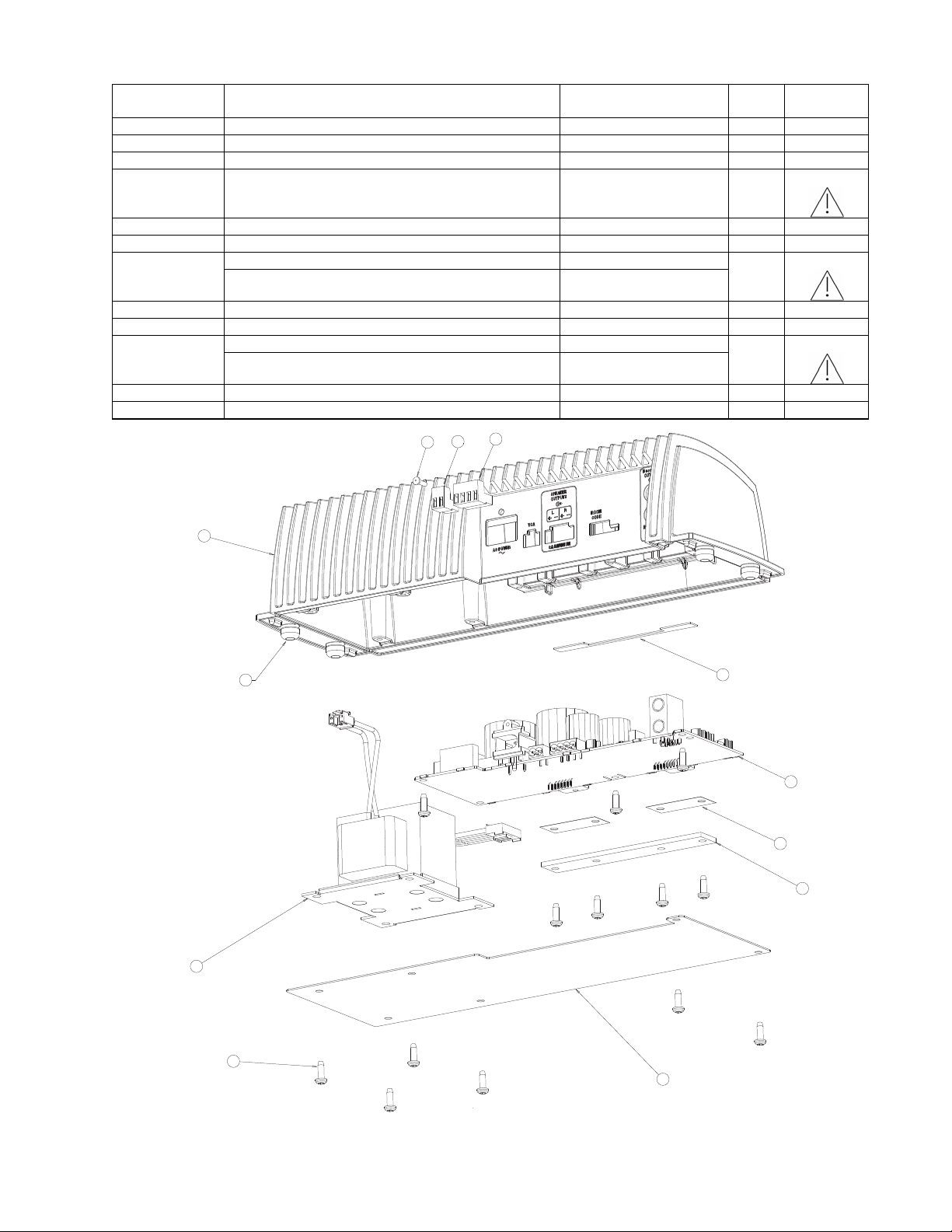
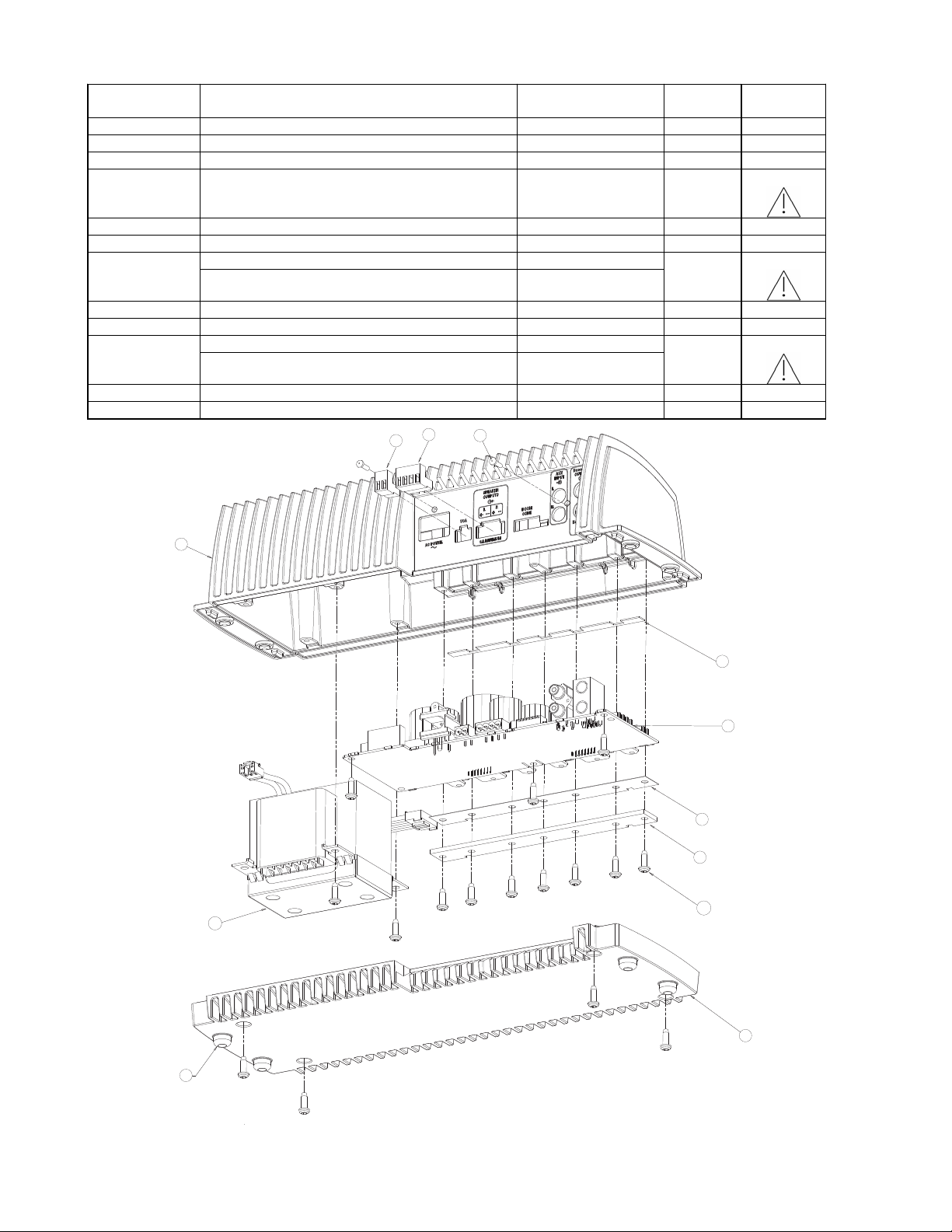
MAIN PART LIST
Reference
Designator
1 CONNECTOR, PLUG-IN, 4 PIN 272953-04 1
2 CONNECTOR, PLUG-IN, 2 PIN 272953-02 1
3 SCREW, HILO, 4-16x.375, PAN, XREC 181621-06 1
4 HOUSING, AMPLIFIER 271724-02 1 1
5 FOOT, RUBBER, PRESS FIT 197418 4
6 TAPE, PAD, INSULATING 328907-0010
7 PCB ASSY, US/CANADA, 120V 288296-103S or 323980-011S 1
PCB ASSY, EURO, UK, AUS, 220/240V 303198-203S or 323981-012S
8 PAD, THERMAL, AMP 320002-002 2
9
10 TRANSFORMER, 120V 271727 1 3
TRANSFORMER, 230V 271790
11 PANEL, BOTTOM 271725-001 1
12 SCREW , TT, 8-32X0.5, PAN, XREC/SQ 255191-08 13
HEATSINK BAR 319884-001
Description Part Number Qty. Note
1
2
1
2
3
4
5
10
6
7
8
9
12
11
Figure 3. Lifestyle® SA-2 Exploded View
7
Page 8
MAIN PART LIST
Reference
Designator
1 CONNECTOR, PLUG-IN, 4 PIN 272953-04 1
2 CONNECTOR, PLUG-IN, 2 PIN 272953-02 1
3 SCREW , HILO, 4-16x.375, PAN, XREC 181621-06 2
4 HOUSING, AMPLIFIER 271724-03 1 1
5 FOOT, RUBBER, PRESS FIT 197418 4
6 TAPE, PAD, INSULATING 328907-0020
7 PCB ASSY, US/CANADA, 120V 288286-103S or 323982-011S
PCB ASSY, EURO, UK, AUS, 220/240V 303199-203S or 323983-012S
8 PAD, THERMAL, AMP 320002-001 1
9
10 TRANSFORMER, 120V 271728 1 3
TRANSFORMER, 230V 271792
11 HOUSING, BOTTOM 271726-001 1
12 SCREW , TT, 8-32X0.5, PAN, XREC/SQ 255191-08 16
HEAT SINK BAR
Description Part Number Qty. Note
1
1 2
319832-001
1
2
3
4
6
7
8
9
10
12
11
5
Figure 4. Lifestyle® SA-3 Exploded View
8
Page 9

ELECTRICAL PART LIST
Resistors
Reference
Designator
RT1 THERMISTOR, 0805, 10K, 5% 197229 SA-3 Only
RT2 THERMISTOR, 0805, 10K, 5% 197229
RT3 THERMISTOR, 0805, 10K, 5% 197229
R1 100 OHM, 0603, .1W, 1% 191465-1000
R2 10K, 0603, .1W, 1% 191465-1002
R3 10K, 0603, .1W, 1% 191465-1002
R4 100K, 0603, .1W, 1% 191465-1003
R5 4.02K, 0603, .1W, 1% 191465-4021
R6 4.02K, 0603, .1W, 1% 191465-4021 SA-3 Only
R7 100K, 0603, .1W, 1% 191465-1003 SA-3 Only
R8 JUMPER, 0805 133627
R9 499 OHM, 0603, .1W, 1% 191465-4990
220 OHM, 2512, 1W, 5% 181895-2200 120V Only R10
470 OHM, 2512, 1W, 5% 181895-4700 230V Only
R11 10K, 0603, .1W, 1% 191465-1002
R12 200 OHM, 0603, .1W, 1% 191465-2000
R13 432 OHM, 0603, .1W, 1% 191465-4320
R14 2.0K, 0603, .1W, 1% 191465-2001
R15 10K, 0603, .1W, 1% 191465-1002
R16 10K, 0603, .1W, 1% 191465-1002
R17 2.0K, 0603, .1W, 1% 191465-2001
R18 100K, 0603, .1W, 1% 191465-1003
R19 100K, 0603, .1W, 1% 191465-1003
R20 1.0K, 0603, .1W, 1% 191465-1001
R21 1.0K, 0603, .1W, 1% 191465-1001 SA-3 Only
R22 10K, 0603, .1W, 1% 191465-1002
R23 100 OHM, 0603, .1W, 1% 191465-1000
R24 100 OHM, 0603, .1W, 1% 191465-1000
R25 10K, 0603, .1W, 1% 191465-1002
R26 100 OHM, 0603, .1W, 1% 191465-1000
R27 100 OHM, 0603, .1W, 1% 191465-1000
R28 100K, 0603, .1W, 1% 191465-1003
R29 100K, 0603, .1W, 1% 191465-1003
R30 100K, ARRAY, SMT, 4 POS, 5% 186433-1044
R31 20.0K, 0603, .1W, 1% 191465-2002
R32 100K, 0603, .1W, 1% 191465-1003
R33 200K, 0603, .1W, 1% 191465-2003
R35 13.3K, 0603, .1W, 1% 191465-1332
R36 1.0K, 0603, .1W, 1% 191465-1001
R37 4.99K, 0603, .1W, 1% 191465-4991
R38 4.99K, 0603, .1W, 1% 191465-4991
R39 7.5K, 0603, .1W, 1% 191465-7501
R40 49.9K, 0603, .1W, 1% 191465-4992
R41 22 OHMS, 0603, .1W, 5% 199403-220
R42 20.0K, 0603, .1W, 1% 191465-2002
R44 10K, 0603, .1W, 1% 191465-1002
R45 10K, 0603, .1W, 1% 191465-1002
R47 100K, 0603, .1W, 1% 191465-1003
R48 20.0K, 0603, .1W, 1% 191465-2002
R49 330 OHM, 2512, 1W, 5% 181895-3300
R50 100K, 0603, .1W, 1% 191465-1003
R51 10K, 0603, .1W, 1% 191465-1002
R52 100K, 0603, .1W, 1% 191465-1003
R53 2.49K, 0603, .1W, 1% 191465-2491
Description Part Number Note
9
Page 10

ELECTRICAL PART LIST
Resistors (continued)
Reference
Description Part Number Note
Designator
R54 20.0K, 0603, .1W, 1% 191465-2002
R55 100 OHM, 0603, .1W, 1% 191465-1000
R56 100K, 0603, .1W, 1% 191465-1003 SA-2 Only
R56 100K, 0603, .1W, 5% 199403-104 SA-3 Only
R57 10K, 0603, .1W, 1% 191465-1002 SA-3 Only
R101 10.0K, 0805, 1% 133625-1002
R102 10K, 0603, .1W, 1% 191465-1002
R103 20.0K, 0603, .1W, 1% 191465-2002
R104 7.5K, 0603, .1W, 1% 191465-7501
R105 49.9K, 0603, .1W, 1% 191465-4992
R106 2.49K, 0603, .1W, 1% 191465-2491
R107 274 OHM, 0603, .1W, 1% 191465-2740
R152 274 OHM, 0603, .1W, 1% 191465-2740
R153 1.18K, 0603, .1W, 1% 191465-1181
R154 200 OHM, 0603, .1W, 1% 191465-2000
R155 100K, 0603, .1W, 5% 199403-104 SA-3 Only
R156 10K, 0603, .1W, 1% 191465-1002
R157 100K, 0603, .1W, 5% 199403-104 SA-3 Only
R158 1.0K, 0603, .1W, 1% 191465-1001 SA-3 Only
R159 1K, 0603, .1W, 5% 199403-102 SA-3 Only
R160 10K, 0603, .1W, 5% 199403-103 SA-3 Only
R161 10K, 0603, .1W, 5% 199403-103 SA-3 Only
R162 1K, 0603, .1W, 5% 199403-102 SA-3 Only
R163 1.0K, 0603, .1W, 1% 191465-1001 SA-3 Only
R164 10K, 0603, .1W, 5% 199403-103 SA-3 Only
R165 10K, 0603, .1W, 1% 191465-1002
R166 1K, 0603, .1W, 5% 199403-102 SA-3 Only
R167 10K, 0603, .1W, 5% 199403-103 SA-3 Only
R168 1K, 0603, .1W, 5% 199403-102 SA-3 Only
R169 330 OHM, 0805, 1/10W, 5% 133626-3315 SA-2 Only
R171 3.9OHM,2512,1W,5% 181895-3R90
R172 1.0K, 1206, 1/4W, 5% 124895-1025
R174 220 OHM, 0805, 1/10W, 5% 133626-2215 SA-3 Only
R175 220 OHM, 0805, 1/10W, 5% 133626-2215 SA-3 Only
R177 330 OHM, 0805, 1/10W, 5% 133626-3315 SA-3 Only
R201 10.0K, 0805, 1/10W, 1% 133625-1002
R202 10K, 0603, .1W, 1% 191465-1002
R203 20.0K, 0603, .1W, 1% 191465-2002
R204 7.5K, 0603, .1W, 1% 191465-7501
R205 49.9K, 0603, .1W, 1% 191465-4992
R206 2.49K, 0603, .1W, 1% 191465-2491
R207 274 OHM, 0603, .1W, 1% 191465-2740
R252 1.0K, 0603, .1W, 1% 191465-1001
R253 1.18K, 0603, 100MW, 1% 191465-1181
R254 200 OHM, 0603, .1W, 1% 191465-2000
R255 100K, 0603, .1W, 5% 199403-104 SA-3 Only
R256 10K, 0603, .1W, 1% 191465-1002
R257 100K, 0603, .1W, 5% 199403-104 SA-3 Only
R258 1.0K, 0603, .1W, 1% 191465-1001 SA-3 Only
R259 1K, 0603, .1W, 5% 199403-102 SA-3 Only
R260 10K, 0603, .1W, 5% 199403-103 SA-3 Only
R261 10K, 0603, .1W, 5% 199403-103 SA-3 Only
10
Page 11

ELECTRICAL PART LIST
Resistors (continued)
Reference
Description Part Number Note
Designator
R262 1K, 0603, .1W, 5% 199403-102 SA-3 Only
R263 1.0K OHM, 0603, .1W, 1% 191465-1001 SA-3 Only
R264 10K, 0603, .1W, 5% 199403-103 SA-3 Only
R265 10K, 0603, .1W, 1% 191465-1002
R266 1K, 0603, .1W, 5% 199403-102 SA-3 Only
R267 10K, 0603, .1W, 5% 199403-103 SA-3 Only
R268 1K, 0603, .1W, 5% 199403-102 SA-3 Only
R269 330 OHM, 0805, 1/10W, 5% 133626-3315 SA-2 Only
R271 3.9OHM,2512,1W,5% 181895-3R90
R272 1.0K, 1206, 1/4W, 5% 124895-1025
R274 220 OHM, 0805, 1/10W, 5% 133626-2215 SA-3 Only
R275 220 OHM, 0805, 1/10W, 5% 133626-2215 SA-3 Only
R277 330 OHM,, 0805, 1/10W, 5% 133626-3315 SA-3 Only
R278 100K, 0603, .1W, 5% 199403-104
R279 100K, 0603, .1W, 5% 199403-104
R301 10.0K, 0805, 1/10W, 1% 133625-1002
R302 10K, 0603, .1W, 1% 191465-1002
R303 20.0K OHM, 0603, .1W, 1% 191465-2002
R304 12.1K, 0603, .1W, 1% 191465-1212
R305 10K, 0603, .1W, 1% 191465-1002
R306 10K, 0603, .1W, 1% 191465-1002
R307 22.1K, 0603, .1W, 1% 191465-2212
R401 10.0K, 0805, 1/10W, 1% 133625-1002
R402 10K, 0603, .1W, 1% 191465-1002
R403 20.0K OHM, 0603, .1W, 1% 191465-2002
R501 10.0K, 0805, 1/10W, 1% 133625-1002
R502 10K, 0603, .1W, 1% 191465-1002
R503 20.0K OHM, 0603, .1W, 1% 191465-2002
R601 10.0K, 0805, 1/10W, 1% 133625-1002 SA-3 Only
R602 10K, 0603, .1W, 1% 191465-1002 SA-3 Only
R603 20.0K OHM, 0603, .1W, 1% 191465-2002 SA-3 Only
R701 10.0K, 0805, 1/10W, 1% 133625-1002 SA-3 Only
R702 10K, 0603, .1W, 1% 191465-1002 SA-3 Only
R703 20.0K OHM, 0603, .1W, 1% 191465-2002 SA-3 Only
R801 10.0K, 0805,1/10W, 1% 133625-1002 SA-3 Only
R802 10K, 0603, .1W, 1% 191465-1002 SA-3 Only
R803 20.0K OHM, 0603, .1W, 1% 191465-2002 SA-3 Only
11
Page 12

ELECTRICAL PART LIST
Capacitors
Reference
Description Part Number Note
Designator
C1 .047UF, 0603, X7R, 50V 191470-473
C2 .047UF, 0603, X7R, 50V 191470-473
C3 .047UF, 0603, X7R, 50V 191470-473 SA-3 Only
C4 .047UF, 0603, X7R, 50V 191470-473 SA-3 Only
C5 .047UF, 0603, X7R, 50V 191470-473
C6 .047UF, 0603, X7R, 50V 191470-473
C7 10000uF, EL, 85, 50V, 20% 170215
C8 4700UF, EL, 85, 25V, 20% 170216 SA-3 Only
C9 4700UF, EL, 85, 25V, 20% 170216 SA-3 Only
C10 10000uF, EL, 85, 50V, 20% 170215
C11 .47uF, FILM, 10%, 250 VAC 250104-474A SA-2 Only 120V
.82UF, FILM, 10%, 250 VDC 250104-824A SA-3 Only 120V
.15uF, FILM, 10%, 400 VAC 306320-154A SA-2 Only 230V
.22uF, FILM, 10%, 275 VAC 306320-224A SA-3 Only 230V
C12 1UF, EL, 85, 50V, 20% 177902-010H
C13 47uF, EL, 5.5MM, 16V, 20% 177902-470C
C14 .047UF, 0603, X7R, 50V 191470-473
C15 .047UF, 0603, X7R, 50V 191470-473
C16 39PF, 0603, COG, 50V, 5% 188454-390
C17 39PF, 0603, COG, 50V, 5% 188454-390
C18 10UF, EL, 85, 16V, 20% 177902-100C
C19 10UF, EL, 85, 16V, 20% 177902-100C
C20 10UF, EL, 85, 16V, 20% 177902-100C
C21 .047UF, 0603, X7R, 50V 191470-473
C23 100PF, 0603, COG, 50V, 5% 188454-101
C24 .047UF, 0603, X7R, 50V 191470-473
C25 .047UF, 0603, X7R, 50V 191470-473
C26 .047UF, 0603, X7R, 50V 191470-473
C28 1UF, EL, 85, 50V, 20% 177902-010H
C29 .047UF, 0603, X7R, 50V 191470-473
C30 .047UF, 0603, X7R, 50V 191470-473 SA-3 Only
C31 .047UF, 0603, X7R, 50V 191470-473
C50 .047UF, 0603, X7R, 50V 191470-473
C101 100PF, 0603, COG, 50V, 5% 188454-101
C102 100PF, 0603, COG, 50V, 5% 188454-101
C103 10UF, EL, 85, 16V, 20% 177902-100C
C104 10UF, EL, 85, 16V, 20% 177902-100C
C105 100PF, 0603, COG, 50V, 5% 188454-101
C150 10UF, EL, 85, 16V, 20% 177902-100C
C152 10UF, EL, 85, 16V, 20% 177902-100C
C153 2700PF, 0603, X7R, 50V 191470-272
C154 .01UF, 0603, X7R, 50V 191470-103
C155 .01UF, 0603, X7R, 50V 191470-103 SA-3 Only
C156 .01UF, 0603, X7R, 50V 191470-103 SA-3 Only
C157 22UF, EL, 85, 35V, 20% 177902-220V
C158 0.1UF, 0805, X7R, 50V 133624
C159 1000PF, 0603, X7R, 50V 191470-102
C160 1000PF, 0603, X7R, 50V 191470-102
C201 100PF, 0603, COG, 50V, 5% 188454-101
12
Page 13

ELECTRICAL PART LIST
Capacitors (continued)
Reference
Description Part Number Note
Designator
C202 100PF, 0603,COG, 50V, 5% 188454-101
C203 10UF, EL, 85, 16V, 20% 177902-100C
C204 10UF, EL, 85, 16V, 20% 177902-100C
C205 100PF, 0603,COG, 50V, 5% 188454-101
C250 10UF, EL, 85, 16V, 20% 177902-100C
C251 1UF, EL, 85, 50V, 20% 177902-010H
C252 10UF, EL, 85, 16V, 20% 177902-100C
C253 2700PF, 0603, X7R, 50V 191470-272
C254 .01UF, 0603, X7R, 50V 191470-103
C255 .01UF, 0603, X7R, 50V 191470-103 SA-3 Only
C256 .01UF, 0603, X7R, 50V 191470-103 SA-3 Only
C257 22UF, EL, 85, 35V, 20% 177902-220V
C258 0.1UF, 0805, X7R, 50V, (10%) 133624
C259 1000PF, 0603, X7R, 50V 191470-102
C260 1000PF, 0603, X7R, 50V 191470-102
C301 100PF, 0603, COG, 50V, 5% 188454-101
C302 100PF, 0603, COG, 50V, 5% 188454-101
C303 10UF, EL, 85, 16V, 20% 177902-100C
C304 .33uF, BOX, 85, 50V, 5% 137127-334
C305 .33uF, BOX, 85, 50V, 5% 137127-334
C401 100PF, 0603, COG, 50V, 5% 188454-101
C402 100PF, 0603, COG, 50V, 5% 188454-101
C403 10UF, EL, 85, 16V, 20% 177902-100C
C501 100PF, 0603, COG, 50V, 5% 188454-101
C502 100PF, 0603, COG, 50V, 5% 188454-101
C601 100PF, 0603, COG, 50V, 5% 188454-101 SA-3 Only
C602 100PF, 0603, COG, 50V, 5% 188454-101 SA-3 Only
C603 10UF, EL, 85, 16V, 20% 177902-100C SA-3 Only
C701 100PF, 0603, COG, 50V, 5% 188454-101 SA-3 Only
C702 100PF, 0603, COG, 50V, 5% 188454-101 SA-3 Only
C703 10UF, EL, 85, 16V, 20% 177902-100C SA-3 Only
C801 100PF, 0603, COG, 50V, 5% 188454-101 SA-3 Only
C802 100PF, 0603, COG, 50V, 5% 188454-101 SA-3 Only
13
Page 14

ELECTRICAL PART LIST
Diodes
Reference
Description Part Number Note
Designator
BR1 RECTIFIER, BRIDGE, 100V, 6A 170214
BR2 RECTIFIER, BRIDGE, 100V, 6A 170214 SA-3 Only
D1 BAV99, SOT23 147239
D3 BAV99, SOT23 147239 SA-3 Only
D5 1N5246, ZEN, 12V, 225MW, 5% 135247-5242
D6 1N5246, ZEN, 12V, 225MW, 5% 135247-5242 SA-2 Only
D7 1N5246, ZEN, 12V, 225MW, 5% 135247-5242 SA-2 Only
D8 ZENER, SOT23, 5%, 5.1V 135247-5231 SA-3 Only
D12 BAV99, SOT23 147239
D13 BAV99, SOT23 147239
D14 ZENER, SOT23, 5%, 5.1V 135247-5231
D16 BAV70, SOT-23 147249
D17 BAV70, SOT-23 147249
D18 BAV99, SOT23 147239
D19 BAV99, SOT23 147239
D150 BAV99, SOT23 147239 SA-3 Only
D152 S10D, 10A, 200V 256405-200 SA-3 Only
D153 S10D, 10A, 200V 256405-200 SA-3 Only
D154 BAV99, SOT23 147239
D250 BAV99, SOT23 147239 SA-3 Only
D252 S10D, 10A, 200V 256405-200 SA-3 Only
D253 S10D, 10A, 200V 256405-200 SA-3 Only
D254 BAV99, SOT23 147239
D255 BAV99, SOT23 147239
DS1 LED, GREEN 256781-002
ZR150 1N5246, ZEN, 12V, 225MW, 5% 135247-5242 SA-3 Only
ZR151 1N5246, ZEN, 12V, 225MW, 5% 135247-5242 SA-3 Only
ZR250 1N5246, ZEN, 12V, 225MW, 5% 135247-5242 SA-3 Only
ZR251 1N5246, ZEN, 12V, 225MW, 5% 135247-5242 SA-3 Only
14
Page 15

ELECTRICAL PART LIST
Transistors
Reference
Description Part Number Note
Designator
Q1 TRIAC, 8A, 600V, D2PAK 197226
Q2 NPN, SOT, 47K 146817
Q3 PNP, SOT, 47K 146818
Q4 PNP, SOT, MMBT3906 148596
Q5 PNP, SOT, MMBT3906 148596 SA-3 Only
Q6 PNP, SOT, MMBT3906 148596
Q7 NPN, SOT, MMBT3904 146819
Q8 NPN, SOT, 47K 146817
Q9 NPN, SOT, MMBT3904 146819
Q10 PNP, SOT, MMBT3906 148596
Q11 NPN, SOT, MMBT3904 146819
Q12 NPN, SOT, MMBT3904 146819
Q13 P, SOT, 2.2K, 2SA1521 180789
Q14 BPLR, N, 40V, 200MA, SOT23 179639
Q15 PNP, SOT, 47K 146818
Q16 NPN, SOT, 47K 146817
Q17 PNP, SOT, 47K 146818
Q150 PNP, SOT, MMBT3906 148596 SA-3 Only
Q151 NPN, SOT, MMBT3904 146819 SA-3 Only
Q152 NPN, SOT, MMBT3904 146819 SA-3 Only
Q153 PNP, SOT, MMBT3906 148596 SA-3 Only
Q154 DARL, TIP146T 172285 SA-3 Only
Q155 DARL, TIP141T 172284 SA-3 Only
Q250 PNP, SOT, MMBT3906 148596 SA-3 Only
Q251 NPN, SOT, MMBT3904 146819 SA-3 Only
Q252 NPN, SOT, MMBT3904 146819 SA-3 Only
Q253 PNP, SOT, MMBT3906 148596 SA-3 Only
Q254 DARL, TIP146T 172285 SA-3 Only
Q255 DARL, TIP141T 172284 SA-3 Only
Integrated Circuits
Reference
Description Part Number Note
Designator
U1 QUAD OP AMP, TLO74D, SO 186112
U2 OP AMP, DUAL, TL072 187619-001 SA-3 Only
U3 VOL CNTRL, SO20, TDA7309D 188941-001
U4 MICRO, ST72324, TQFP, 32K, PROG 303687-001
U5 TRANS, DUAL, SO-16, NJM13700 188650-001
U6 QUAD OP AMP, TLO74D, SO 186112
U7 RELAY SSR, HI-RON, 6-PIN, SMT 253843
U8 VOLT REG, POS, SOT89, +8V 258167-08
U9 VOLT REG, NEG, 7908, SOT89 260688-08
U10 VOLT REG, POS, SOT89, +5V 258167-05
U150 POW ER AMP, AUDIO, TDA7294 170156 SA-2 Only
U150 POWER AMP, AUDIO, TDA7293 HS 275177-001 SA-3 Only
U250 POW ER AMP, AUDIO, TDA7294 170156 SA-2 Only
U250 POWER AMP, AUDIO, TDA7293 HS 275177-001 SA-3 Only
15
Page 16

ELECTRICAL PART LIST
Miscellaneous
Reference
Description Part Number Note
Designator
F1 FUSE, 5X20MM, SLO-BLO, 3.15A 177311-03150
F1A FUSECLIP, 5MM 178548
F1B FUSECLIP, 5MM 178548
J1 CONN, AC POWER 146563 120V Only
CONN, AC POW ER 145306 220/240V Only
J2 CONN, HEADER, LOCKING, TOP
ENTRY
J3 HEADER, MED CURRENT, 5 PIN 133220-05 3
J4 CONN, PIN JACK, DUAL, VERTICAL 273167 SA-3 Only
J5 CONN, DUAL, DIN 199553 or 268894-002
J6 CONNECTOR, RIGHT ANGLE 272952-02
J7 CONNECTOR, RIGHT ANGLE 272952-04
J8 CONN, HEADER, X2, VERT, .1SP, 10P 260636-10
JP1 JUMPER 124896 SA-2 Only
JP2 JUMPER 124896 SA-2 Only
JP3 JUMPER 124896 SA-2 Only
JP4 JUMPER 124896 SA-2 Only
L1 330 OHM, FERRITE BEAD, 0603 268373-331
S1 SW, DIP, SIDE ACTUATED, LSA-2 274837-005 SA-2 Only
S1 SW, DIP, SIDE ACTUATED, LSA-3 274837-007 SA-3 Only
Y1 XTAL, SMD, 105, AT41CD2,
12.2880MZ
193369-002 3
26992312R2C20
3
3
16
Page 17

SA-2 DISASSEMBLY PROCEDURES
1. PCB Disassembly and Transformer Removal
1.1 On the rear panel, remove the phillips-head screw identified below that secures the AC
power jack to the amplifier housing.
1.2 Remove the six phillips-head screws indicated to remove the amplifier housing bottom panel.
Lift off the bottom panel.
Note: The transformer is secured to the amplifier housing by four of these screws.
17
Page 18

SA-2 DISASSEMBLY PROCEDURES
1.3 Remove the four phillips-head screws that secure the IC pressure bar to the amplifier hous-
ing. Lift off the pressure bar.
1.4 Remove the three phillips-head screws that secure the PCB assembly to the amplifier
housing.
1.5 Lift the PCB assembly and transformer up and out of the amplifier housing. Make sure that
the rear panel connectors clear the housing.
1.6 Make a note of how the transformer is plugged into the PCB assembly and remove the two
transformer cables from the PCB assembly jacks at J2 and J3.
18
Page 19

SA-3 DISASSEMBLY PROCEDURES
1. PCB Disassembly and Transformer Removal
1.1 On the rear panel, remove the phillips-head screws identified below that secures the AC
power jack to the amplifier housing as identified below.
1.2 Remove the four phillips-head screws indicated to remove the bottom panel to the amplifier
housing. Lift off the bottom panel.
Note: The transformer is secured to the amplifier housing by two of these screws.
19
Page 20

SA-3 DISASSEMBLY PROCEDURES
1.3 Remove the seven phillips-head screws that secure the plate clamp to the amplifier housing.
Lift off the plate clamp.
1.4 Remove the three phillips-head screws that secure the PCB assembly to the amplifier
housing.
1.5 Remove the two phillips-head screws identified, these are the remaining two screws that
secure the transformer to the amplifier housing.
20
Page 21

SA-3 DISASSEMBLY PROCEDURES
1.6 Lift the PCB assembly and transformer up and out of the amplifier housing. Make sure that
the rear panel connectors clear the housing.
1.7 Remove the two transformer cables from the PCB assembly jacks at J2 and J3.
21
Page 22

TEST SET-UP
A
Equipment Needed:
• DC Power Supply
• Audio signal generator
• 2 - 6 Ohm, 100 Watt load resistors
• Audio input cable part number 278128
• Connector plug part number 272953-04
DIP Switch Settings
Up Stereo/Mono switch (up is stereo mode)
B Down Enable/Disable auto-detect of RCA audio input (down is disabled)
C Down Slave/Master switch (down is master mode)
6 Down Room Address 1
7 Down Room Address 2
8 Down Room Address 3
9 Up Room Address 4
Note:
Note: "DIP switch settings only take effect after the unit has been powered OFF for 30
seconds, then turned ON"
st
bit (MSB)
nd
bit
rd
bit
th
bit (LSB)
Set up the unit under test as described below.
1. Set the DIP Switches as described above.
2. Connect the DIN connector of cable part number 278128 to the amplifier Bose
input connector.
3. Connect the left and right RCA connectors to a signal generator.
4. Load the left and right outputs with a 6 Ohm, 100W resistor by using connector plug
part number 272953-04.
5. With the unit unpowered apply +2.5 VDC to the ring (middle conductor) of the 3.5mm stereo
mini plug. Connect the ground of the power sleeve to the sleeve (long conductor) of the plug.
Note: The microcontroller will respond by placing the unit in a special test mode. The unit
will power ON (LED will turn to solid green), source channel 2 will be selected, volume
level will be set to maximum and the amplifier outputs will unmute.
6. Apply AC Power.
Note: The 2.5 VDC must be applied before AC voltage is applied.
LED Status Indicator
The green LED, located next to the dip switches on the rear of the unit, indicates the operational mode of the amplifier.
LED activity Mode
Constant slow blinking Power off (Standby)
Continuously lit Power on
Lit but rapidly flickering Slave
Blinking Quickly Receiving commands
®
link DIN
22
Page 23

TEST PROCEDURES
1. Channel Gain Test
1.1 Apply a 100 mVrms, 1 kHz signal to the left and right channel inputs.
1.2 Reference a dB meter to the applied signal.
1.3 Measure the output level at the left and right channel.
1.3.1 Left Channel Output: 34.9 +/- 1.5dB (5.5 +/- 0.5 Vrms)
1.3.2 Right Channel Output: 34.9 +/- 1.5dB (5.5 +/- 0.5 Vrms)
2. Output Noise ( A weighted, inputs shorted)
2.1 Short the left and right channel inputs.
2.2 Measure the left and right outputs.
2.2.1 Left Channel: <500 uVrms
2.2.1 Left Channel: <500 uVrms
3. Large Signal Distortion
3.1 Apply a 250 mVrms, 1 kHz signal to the left and right channel inputs.
3.2 Measure the THD + Noise (400 - 30kHz bandwidth).
3.2.1 Left Channel: < 0.2%
3.2.2 Right Channel: < 0.2%
4. Compressor Distortion
4.1 Apply an 875 mVrms, 1 kHz signal to the left and right channel inputs.
4.2 Measure the output level at the left and right channel.
4.2.1 Left Channel: < 6.0%
4.2.2 Right Channel: < 6.0%
23
Page 24

C2
C3
C6
271715-001
C4
C5
6
JP2
Q6
R16
R2
R3
RT
C152
C153
C157
C159
ZR150
C15
C160
D153
D154
J
1
Q153
R16
R168
R169
R174
R177
C2
25
C25
D252
JP4
Q252
Q7
R12
R1
R266
RT3
ZR251
C13
C25
C254
C257
C259
C26
C260
C603
3
4
D1
17
D17
D250
D254
Q250
Q251
Q8
R252
253
R25
R25
R25
262
R26
R264
R265
R26
R269
R42
R55
U3
U4
ZR250
C103
103
C20
255
C304
C403
C702
C802
D12
D8
JP3
Q253
Q4
R102
R202
R261
R268
R302
R402
R502
U1
U2
U6
C
04
C18
EUR
27
D16
Q2
Q3
S1
J8
R25
R28
R2
R30
R47
Y1
C23
C602
J5
R15
R16
R41
R802
C
R
2
C
271715
0
C
C
R
T2
4
6
J
3
5
2
2
2
2
R1
R
R
66
C15
R
R1
D1
3
9
C
55
C
C
4
C1
5
R2
21
R
C
R2
R
250
66
R2
6
4
C
Q2
7
3
2
3
D25
1
R2
6
59
9
51
R2
54
57
53
64
52
304
R2
R
Q
Q
6
3
R2
63
D2
D2
67
53
54
56
62
R2
Y
4
R
R
2
D17
R
J
J
U
D8
02
C103
R2
C7
C
U3
U6
Q
Q
D
D8
C403
3
C
C27
S1
J8
R
1
LSA2
LSA3
EUR
US
US
J2
T/U
Figure 8. Lifestyle
®
SA-2 & SA-3 Amplifier PCB Rev. 0 Topside Component and Etch Layout Diagram
TEC
ICT
T/A FCT
C11
F1
J1
J6
U7
Q1
3.15A L 250V
T
J3
BR2
D1
D
C7
1
C10
BR1
P
Q155
D152
U150
P
Q154
5
C12
U10
U8
J7
C150
DS1
J4
C250
C8
C9
C251
D18
C28
Q9
C70
C305
P
C252
Q255
U250
Q254
D253
WT2
C203
C303
C204
24
1
U5
C19
Page 25

Figure 9. Lifestyle
C1
D5
R5
R6
R7
R9
R14
C154
Q150
R15
R156
R164
Q11
Q15
R50
R51
U9
Q14
R279
R53
15
C24
Q17
25
R258
R44
R48
R54
R56
R57
C102
C105
C202
C205
C29
C302
C402
C50
C502
D13
R103
R105
R106
R11
R203
R205
R206
R22
R23
R27
274
R303
R304
R305
R306
R307
31
R32
R33
R35
R36
R40
R403
R503
R602
R603
R703
R803
R104
R204
R37
R38
R1
C14
D19
R45
C15
R171
R27
R278
C17
R20
R21
C
D
R
4
1
R
6
7
R
56
R
Q5
5
R
55
55
64
R1
51
R1
54
56
C
R1
R
Q
R
R
7
R
3
9
58
8
R2R2R2
57
4
R
R
4
R
R2
3
2
C
R1
02
C
2
3
C
R
03
R
R4
C4
R
0
R
5
R
06
4
6
C
R2
5
R
5
R
R3
06
R
36
R2
R2
3
R3
C5
R
R2
7
R
R2
2
R
3
R
R
R
R
14
C
R
5
C
R
R
8
5
58
71
1
R
C
71
5
5
C
C
21
0
R
7
D3
®
SA-2 & SA-3 Amplifier PCB Rev. 0 SMD Etch and Component Layout Diagram
R10
R49
25
Page 26

Lifestyle® SA-2 & SA-3 Stereo Amplifier
SA-2
SA-3
©
2009 Bose Corporation
Service Manual
Reference Numbers 271720 & 271721-SM Rev. 01
Electronic Copy Only
Page 27

ECN 45669 REV00 - REV01
SPECIFICATIONS AND FEATURES SUBJECT TO CHANGE WITHOUT NOTICE
Bose Corporation
The Mountain
Framingham Massachusetts USA 01701
Reference Numbers 271720 & 271721-SM Rev. 01 10/2009
http://serviceops.bose.com
 Loading...