

Page 1

Entero™ System Installation/
Troubleshooting Guide
®
®
©
1999 Bose Corporation
Troubleshooting Guide
Part Number: 251763 Rev. c
Page 2

CONTENTS
Audience ........................................................................................................................................... 3
Safety Information............................................................................................................................ 4
Electrostatic Discharge Sensitive (ESDS) Device Handling ........................................................ 4
Entero™ System Installation Flow Chart....................................................................................... 5
Entero System Troubleshooting Flow Chart ................................................................................. 6
Entero Computer Related Problems Troubleshooting Flow Chart.............................................. 7
Entero Network Troubleshooting Flow Chart................................................................................ 8
Entero Hardware Troubleshooting Flow Chart.............................................................................. 9
Section 1: PCC-10 Laptop PC Network Adapter Card Information.......................................10-19
Figure 1.1. PCC-10 Card Network Port Connector (not to scale) .................................................. 18
Figure 1.2. PCC-10 Card Network Cable Connector (not to scale) ............................................... 18
Figure 1.3. PCC-10 Card Network Port Electrical Interface ........................................................... 19
Table 1.1. PCC-10 Network Port Electric Interface Description ..................................................... 19
Section 2: PCNSI Desktop PC Network Adapter Interface Card Information ...................... 20-27
Figure 2.1 PCNSI Card Mechanical Layout and Interfaces ........................................................... 20
Table 2.1 PCNSI Card Interfaces................................................................................................... 20
Table 2.2 SMX-Compatible Transceivers....................................................................................... 21
Figure 2.2 Setting the PCNSI Base Address with switch S1.......................................................... 22
Figure 2.3 PCNSI Default Base Address Setting ........................................................................... 22
Table 2.3 Typical I/O Address Usage in PC-Compatibles .............................................................. 22
Table 2.4 Typical Interrupt Request Usage in PC-Compatibles ..................................................... 24
Section 3: FTT-10A Network Information................................................................................28-33
Figure 3.1 Block Diagram of a LonWorks
Figure 3.2 FFT-10A Free Topology Network Diagram.................................................................... 29
Table 3.1 Cable Types and Typical Parameters............................................................................. 30
Table 3.2 Free Topology Network Specifications ........................................................................... 31
Section 4: Echelon® Model 71000 Router Information........................................................... 34-41
Figure 4.1 Sample Router Installation............................................................................................ 34
Figure 4.2 Router Assembly Using the Router Core Module ......................................................... 35
Figure 4.3 Echelon Model 71000 Router Diagram......................................................................... 36
Table 4.1 Model 71000 Router Interfaces ...................................................................................... 37
Figure 4.4. RJ-45 Connector Pin-out Diagram............................................................................... 38
Figure 4.5 Network Termination Circuits for TP/XF and TP/RS485 Networks ............................... 39
Table 4.2 Power Supply Characteristics......................................................................................... 40
Figure 4.6 Model 71000 Routing Mounting Bracket Fabrication Diagram ..................................... 41
Section 5. K11 and K12 Keypad Information.......................................................................... 42-46
Figure 5.1 K11 and K12 Keypads for Entero System..................................................................... 42
Figure 5.2 K12 Keypad and Cover................................................................................................. 43
Figure 5.3 K11 and K12 Keypad Base Module Front View (without keypad)................................. 45
Figure 5.4 K11 and K12 Keypad Schematic Diagram.................................................................... 46
Section 6: Junction Box and Wiring Guidelines ......................................................................... 47
Figure 6.1 Typical Topology for 78kbps, 1.25Mbps, and RS-485 Networks................................... 47
Figure 6.2 Typical Network Topology for Free Topology Networks ................................................ 48
Figure 6.3 Stub Junction Box Wiring Diagram ............................................................................... 49
Figure 6.4 Local Loop Terminal Junction Box Diagram.................................................................. 50
Section 7: SE-16 Audio Processor Disassembly/Assembly Procedures ................................. 51
Section 8: General Troubleshooting ............................................................................................ 52
Service LED Behavior............................................................................................................... 52-53
Figure 8.1 Service LED Behavior Diagram .................................................................................... 52
Section 8: General Troubleshooting ............................................................................................ 53
Section 9: Reference Information............................................................................................ 54-56
®
Device on a Twisted-Pair Network .............................. 28
2
Page 3

AUDIENCE
This Installation/Troubleshooting Guide is intended for anyone who is installing, maintaining, or
troubleshooting a Bose® Entero™ System; as well as an aid for instructors setting up a training
course on the Entero System.
It contains information about the various components that make up an Echelon® LonWorks
network as they pertain to the Bose Entero System. This includes computer setup
information; Echelon Network Interface Card information; network wiring, router, and junction
box information; and flow charts to direct you to the appropriate service manual for Bose
hardware.
It is not intended to be a definitive answer to any and all problems that can be encountered
when using an Entero system. It is intended to help point you in the direction where you can
find answers to your installation and troubleshooting problems.
Note: Your Entero System as installed may or may not include some of the items as described
in this document.
®
CAUTION: The components listed in this Installation/Troubleshooting Guide
contain no user-serviceable parts. To prevent warranty infractions,
refer servicing to warranty service centers or factory service.
PROPRIETARY INFORMATION
THIS DOCUMENT CONTAINS PROPRIETARY INFORMATION OF
BOSE® CORPORATION WHICH IS BEING FURNISHED ONLY FOR
THE PURPOSE OF SERVICING THE IDENTIFIED BOSE PRODUCT
BY AN AUTHORIZED BOSE SERVICE CENTER AND SHALL NOT
BE REPRODUCED OR USED FOR ANY OTHER PURPOSE.
3
Page 4

SAFETY INFORMATION
1. Parts that have special safety characteristics are identified by the symbol on schematics or
by special notes on the parts list. Use only replacement parts that have critical characteristics
recommended by the manufacturer.
2. Make leakage current or resistance measurements to determine that exposed parts are
acceptably insulated from the supply circuit before returning the unit to the customer. Use the
following checks to perform these measurements:
A. Leakage Current Hot Check-With the unit completely reassembled, plug the AC line cord
directly into a 120V AC outlet. (Do not use an isolation transformer during this test.) Use a
leakage current tester or a metering system that complies with American National Standards
Institute (ANSI) C101.1 "Leakage Current for Appliances" and Underwriters Laboratories (UL)
1492 (71). With the unit AC switch first in the ON position and then in OFF position, measure
from a known earth ground (metal waterpipe, conduit, etc.) to all exposed metal parts of the
unit (antennas, handle bracket, metal cabinet, screwheads, metallic overlays, control shafts,
etc.), especially any exposed metal parts that offer an electrical return path to the chassis. Any
current measured must not exceed 0.5 milliamp. Reverse the unit power cord plug in the outlet
and repeat test. ANY MEASUREMENTS NOT WITHIN THE LIMITS SPECIFIED HEREIN
INDICATE A POTENTIAL SHOCK HAZARD THAT MUST BE ELIMINATED BEFORE RETURNING THE UNIT TO THE CUSTOMER.
B. Insulation Resistance Test Cold Check-(1) Unplug the power supply and connect a
jumper wire between the two prongs of the plug. (2) Turn on the power switch of the unit. (3)
Measure the resistance with an ohmmeter between the jumpered AC plug and each exposed
metallic cabinet part on the unit. When the exposed metallic part has a return path to the
chassis, the reading should be between 1 and 5.2 Megohms. When there is no return path to
the chassis, the reading must be "infinite". If it is not within the limits specified, there is the
possibility of a shock hazard, and the unit must be repaired and rechecked before it is returned
to the customer .
ELECTROSTATIC DISCHARGE SENSITIVE (ESDS)
DEVICE HANDLING
This unit contains ESDS devices. We recommend the following precautions when repairing,
replacing or transporting ESDS devices:
• Perform work at an electrically grounded work station.
• Wear wrist straps that connect to the station or heel straps that connect to conductive floor
mats.
• Avoid touching the leads or contacts of ESDS devices or PC boards even if properly
grounded. Handle boards by the edges only.
• Transport or store ESDS devices in ESD protective bags, bins, or totes. Do not insert
unprotected devices into materials such as plastic, polystyrene foam, clear plastic bags,
bubble wrap or plastic trays.
4
Page 5

Entero™ System Installation Flow Chart
START
System Design
1. Determine the audio and control requirements
2. Design the network
3. Generate the Entero™ System equipment list
4. Determine the special power requirements
System
Installation
1. Follow the guidelines for cable lengths, types,
and terminations
Network
Commissioning
1. Set up the PC
2. Install the routers
3. Add and configure devices in the Entero System software.
4. Check the network commissioning
Device
Programming
1. Define and set up the device finder and custom views in Entero
2. Add the master controls required
3. Add the On/Off controls required
4. Add mapped faders
5. Consolidate control functions
6. Set up snapshots
7. Program Contact Closure Interfaces
5
Page 6

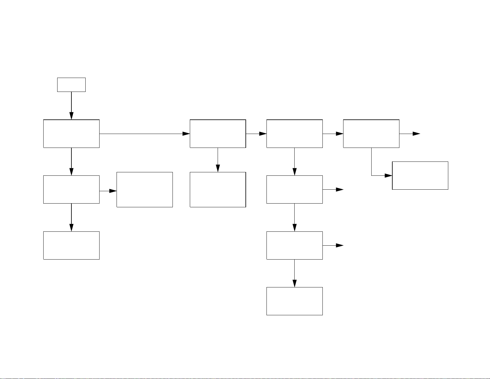
Entero™ System Troubleshooting Flow Chart
START
Is the system
working
properly?
No
Does the
computer boot-up
properly?
Yes
Can you
communicate
with all of the nodes
on the network?
Yes
Yes
No
No
Can you control
the system using
the GUI?
No
Go to the
Computer-Related
Problems T/S
Flow Chart
Go to the
Network T/S
Flow Chart
Done
Yes
Does the hardware
in each section
respond to the
GUI and/or keypad?
Yes
Is clear-sounding
audio coming out of
each speaker?
Yes
Done
No
No
Go to the
Hardware T/S
Flow Chart
6
Page 7
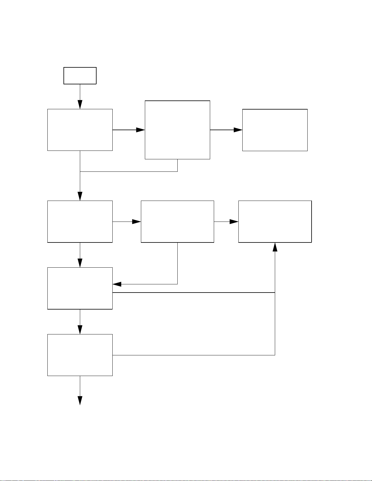
START
Entero™ Computer Related Problems Troubleshooting Flow Chart
Does the computer
boot up properly?
No
Does the computer
7
have AC Mains
power?
No
Restore AC Mains
power.
Yes
Computer failure.
Yes
all necessary
Repair and
re-install
software.
Does the Entero™
System software
open properly?
No
Re-install the
Entero System
software and all
system-specific
files.
Yes
Does the Echelon
Network Interface
Card work
properly?
No
Re-install LNS
software.
Verify software
configuration. OK?
No
Hardware failure,
verify setup and
configuration.
OK?
No
Replace Echelon
Network Interface
Card
®
Yes
Yes
Yes
Can you control
all sections of
the system
using Entero?
No
Done
Done
Yes
Done
Go to the network
trouble-shooting
flow-chart.
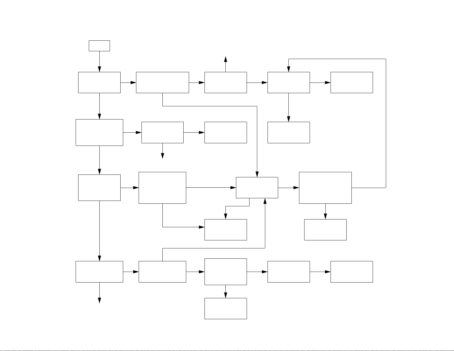
Page 8
Entero™ Network Troubleshooting Flow Chart
START
Check router
Can you
communicate
with all of the
sections of the
network?
No
hardware and
configuration
in the Entero™
System software
for the affected
section(s). OK?
Yes
Yes
No
Check the wiring,
connections,
and terminations
for the
affected section(s).
Do all of the nodes
in each section
respond?
Yes
Can you control
the hardware on
the node
using the GUI?
Yes
Is clear-sounding
audio
coming from
each loudspeaker?
No
No
No
Verify affected
node's configuration
in Entero.
Does the node
respond?
Yes
No
Go to the Hardware
Troubleshooting
Flow Chart
Yes
Done
8
Page 9
START
Are the SE-16
audio processors in
the affected section
working properly?
Yes
Using Entero, verify
signal flow through all
channels of the affected
No
SE-16 processor. OK?
Yes
No
Done
Yes
Reconfigure the
affected SE-16
module in Entero.
OK?
No
Does the
affected SE-16
channel have a
clean input signal?
Yes
No
Entero™ Hardware Troubleshooting Flow Chart
Check the source
hardware
and cabling
Can you control and
monitor the amplifiers
in the affected section
using the Entero™
system software?
Yes
9
Is a clean audio
signal coming out
of each amplifier
in the affected
section?
Yes
Is clear-sounding
audio coming out of
each loudspeaker in
the affected section?
Yes
No No
No
No
Reconfigure the
affected ACM-1
in the Entero
software.OK?
Yes
Done
Using the Entero
software, verify
that the operating
parameters of the
affected amplifier
are within limits. OK?
Yes
No
Is a clean audio
signal coming from
the amplifier that is
driving the speaker?
manual for repair.
No
from the amplifier
to the loudspeaker.
Yes
Refer to the
ACM-1 service
Refer to the
1600/1800VI
service manual
for repair.
Check the wiring
and connectors
OK?
No
manual for repair.
Does the
affected amplifier
have a clean input
signal?
Yes
Replace/repair the
Yes
Refer to the
SE-16 service
No
defective
loudspeaker.
Does the SE-16
audio processor
driving the amplifier
have a clean output
signal on that channel?
Yes
Refer to the
1600/1800VI
service manual
for repair.
Refer to the
appropriate service
manual for repair.
No
Done
Repair/replace
defective
wiring.
Page 10

Section 1: PCC-10 Laptop PC Network Adapter Card Information
PCC-10 Network Adapter Card Installation Process
Note: Installation of the PCC-10 software must precede insertion of a PCC-10 card into a PC
Card Type II (PCMCIA) slot.
Failure to install the software before inserting the card will render the card unusable until the
software and card are removed, and then reinstalled in the correct order.
The six steps of the installation process are as follows:
• Install Windows PCMCIA driver if not currently installed. A Windows
®
PCMCIA driver must
be installed prior to PCC-10 card installation. Under Windows 95, the PC Card driver is
installed automatically when the PC Card drive is installed. (if this is not present, please
consult your Windows 95 documentation).
• If you have purchased the LonManager
®
PCC-10 Protocol Analyzer, install the protocol
analyzer applications following the instructions provided in the LonManager Protocol User's
Guide. Note that you cannot use the LonManager ISA Protocol Analyzer card and a PCC-10
card in the same PC.
• Install the PCC-10 driver software as described below.
• Insert the PCC-10 card as described later in this section.
• Attach the PCC-10 network card cable.
• Install the LonWorks
Note: If the LonManager Protocol Analyzer software is installed after installing the PCC-10
card software, the PCC-10 card software must be re-installed.
PCC-10 Network Adapter Card Software Installation
®
Network Services (LNS) software, if needed.
Prior to installation, ensure that the computer is running the Windows 95 Operating System.
The PCC-10 software cannot be installed from DOS or a DOS shell.
1. Close all open programs.
2. Insert the installation diskette into the PC.
3. Click the START button on the Windows 95 task bar and select the RUN command.
4. When prompted for a program name, enter the following:
a:\SETUP.EXE
If necessary, replace a: with the drive letter that corresponds to the drive containing the
PCC-10 installation diskette.
5. When prompted with a list of languages, click on the desired language. A checkmark will
appear to the left of the language to be installed.
10
Page 11

Section 1: PCC-10 Laptop PC Network Adapter Card Information
PCC-10 Network Adapter Card Software Installation (continued)
6. When prompted for a destination directory, enter the desired installation directory. By default
®
this directory is c:\lonworks, unless previous LonWorks
products have been installed and
registered a different path in the Windows® Registry. The path may be modified using the
Browse button; however, if a directory other than c:\lonworks is chosen, the PCC-10 images path will have to be specified to enable use of the PCC-10 card. This is accomplished
during PCC-10 configuration.
7. When the 16-bit Applications Support prompt appears, select "Yes" to enable the use of
16-bit applications with the PCC-10 card. This causes the installation program to add references to the DOS CONFIG.SYS file for the 'stub' device drivers named PCCLON1 and
PCCLON2. This allows existing 16-bit applications, such as the LonManager® Protocol
Analyzer's channel interface maker tool, to recognize these device names and use the PCC-10
card as a network interface. If the PC has more than two PC card slots, two additional stub
device drivers can be created manually. To do so, add the following lines to the CONFIG.SYS
file:
DEVICE=C:\LONWORKS\BIN\LDVSTUB.SYS /D:PCCLON3
DEVICE=C:\LONWORKS\BIN\LDVSTUB.SYS /D:PCCLON4
There is a limit of four (4) PCC-10 cards on a single PC.
To access the PCC-10 card, the "PCCLONn" network interface naming convention must be
used, rather than the "LONn" naming convention used with other Echelon® products. Use of
this naming convention will direct the software to use the PCC-10 card device driver under
Windows rather than attempting to access the device under DOS.
Once this driver is installed and active, existing 16-bit Windows applications can access the
PCC-10 card using the ldv_open(), ldv_close(), ldv_read(), and ldv_write()
functions provided by the WLDV.DLL file.
The installation software installs a new WLDV.DLL file, replacing any previous versions of the
file. The updated WLDV.DLL file is fully backward compatible with previous versions.
8. If the installation software discovers the SYSTEM.INI entry that loads the ISA-bus driver,
ECHLMPA.386, it will comment out the entry and display the message:
"SETUP has modified your SYSTEM.INI file by removing the following
entry: device=echlmpa.386."
It is not possible to use the ISA-bus protocol analyzer card and the PCC-10 card on the
same PC.
9. The installation software for the Windows 95 version will issue a prompt to add a DOS
virtual-mode device driver file named LDVVDD.SYS to the DOS CONFIG.SYS file to support
DOS applications to be used in a Windows 95 DOS shell/window. The following line is added
to the CONFIG.SYS file:
DEVICE=C:\LONWORKS\BIN\LDVVDD.SYS /D1
11
Page 12

Section 1: PCC-10 Laptop PC Network Adapter Card Information
PCC-10 Network Adapter Card Software Installation (continued)
10. Installation is complete. At the prompt to restart the computer, remove the PCC-10
®
installation diskette and restart the computer. Note that Windows
will not recognize the
PCC-10 card until the computer is restarted.
Windows 95 Warning
Some Windows 95 computer systems come equipped with hardware (such as a CDROM
drive) that use its own card and socket services. These services replace those provided by
Windows 95, and may contain incompatibilities that prevent the PCC-10 card from functioning.
One example is SystemSoft's CardWorks™ PCMCIA drivers, which are packaged with the
Axonix ProMedia™ Portable CDROM Drive. To allow the PCC-10 card to operate with these
drivers, some of its services must be disabled by commenting out the lines in the PC's
CONFIG.SYS file that contain the following instructions:
C:\CARDWORK\SSTOPIC.EXE, C:\CARDWORK\ATADRV.EXE,
C:\CARDWORK\MTAA.EXE, C:\CARDWORK\MTAB.EXE,
C:\CARDWORK\MTI1.EXE, C:\CARDWORK\MTI2P.EXE,
C:\CARDWORK\MTATM.EXE, C:\CARDWORK\MTHB2.EXE,
C:\CARDWORK\MTSRAM.EXE, C:\CARDWORK\MTTDRV.EXE,
C:\CARDWORK\FTL.EXE, C:\CARDWORK\CARDID.EXE,
C:\CARDWORK\AXONIXXR.EXE
PCC-10 Network Adapter Card Software Removal
To remove the PCC-10 software, use the Uninstall control panel as follows:
1. Close the "LonWorks® Plug n' Play" control panel, if it is open.
2. Choose the "Add/Remove Programs" icon from the Control Panel folder.
3. Select "LonWorks PCC-10" from the list under the Install/Uninstall tab.
4. Click the "Add/Remove..." button.
5. Confirm file deletion at the prompt. Most of the PCC-10 software will be removed
automatically.
6. The LonWorks Plug n' Play control panel must be removed manually. Close the Control
Panel folder if it is open. Rename C:\Windows\System\Pcc10cfg.cpl to
C:Windows\System\Pcc10cfg.cpx, (where C: is the drive containing the Windows
folder), then remove the file Pcc10cfg.cpx by placing it in the Recycle Bin. It is not
necessary to empty the Recycle Bin at this time.
Windows will not allow deletion of Pcc10cfg.cpl because it is registered as a control panel.
Renaming the file circumvents this Windows 95 restriction.
7. If necessary, edit the CONFIG.SYS file to remove any references to the LDVSTUB.SYS
driver.
12
Page 13

Section 1: PCC-10 Laptop PC Network Adapter Card Information
PCC-10 Laptop Network Card Hardware Installation
Note: If the software has not been installed, please install it first using the procedures outlined
earlier in this section. The Windows
without the software installed.
The PCC-10 card conforms to the Personal Computer Memory Card International Association's
(PCMCIA) standard for hot plug-in. The PCC-10 card will not be harmed if it is inserted into, or
removed from, a PC Card (PCMCIA) slot that conforms to this standard, whether the
computer is on or off. In addition, the PCC-10 card is recognized as a UL Listed Accessory
and is designed to be used with UL Listed equipment.
Do not force the PCC-10 card into the PC card slot. The PCC-10 card is keyed and can only
be inserted one way into the PC card slot. In a Windows 95 environment, insertion of the
PCC-10 card will cause the operating system to produce two brief tones: a low tone followed
by a higher tone. Extracting the card will produce the tones in reverse order: high then low. If a
device's properties window is open in the System Control Panel, the tones will be produced
after the window is closed to confirm that the device is inserted correctly. Additionally, a PC
Card icon may appear in the status area to the right of the Windows 95 taskbar.
®
operating system will not recognize the PCC-10 card
• If the computer was rebooted after installation of the software, insert the PCC-10 card into
an open PC card slot. Otherwise, reboot the computer before insertion.
• Under Windows 95, the device driver for the PCC-10 card is not loaded until the first
PCC-10 card is recognized. Likewise, when the last PCC-10 card is removed, the device
driver is unloaded, thus freeing any system resources it was using.
• Each PCC-10 card requires a single, dedicated interrupt request (IRQ) and four contiguous
bytes of I/O address space starting on a modul0-4 based address.
• Removal of a PCC-10 card while an application is using the card will result in a loss of
communication with the device, which cannot be restored by re-inserting the card. Some
applications will display unusual behavior, and will not properly function. Any application
using the PCC-10 card must be restarted if, a PCC-10 card has been removed during use
to ensure proper operation of the device and software.
• Under Windows 95, the first time a PCC-10 card is inserted into a running PC, a window will
appear with the words "Echelon Corp.-PCC-10". Another window will appear stating that the
Windows operating system is building a new database from the device information installed
by the PCC-10 installation diskette. The new hardware can be configured when the PC has
finished writing the device information.
13
Page 14

Section 1: PCC-10 Laptop PC Network Adapter Card Information
®
PCC-10 Card Hardware Revisions under Windows
95
If a different, or newer, version of the PCC-10 card is inserted into the PC Card slot, a
"New Hardware Found" window may be presented. In this event, a prompt will appear to select
which driver should be installed for the new hardware. If the new hardware states that it is the
"PCC-10 LonWorks® Network Interface", then choose the Windows default driver. This is the
driver that is installed on the PC during the PCC-10 software installation. If the driver has a
different name, you must be sure you have installed the proper software for that card. If not,
click Cancel, remove the card, and then install the software for that card.
If the Windows default driver choice cannot be selected (or is shown in gray), the PCC-10
Card may have been erroneously inserted before the software was installed and the system
rebooted. In this case, click Cancel, remove the PCC-10 Card if it is in a PC Card slot, then
follow the Windows 95 Network Adapter Card Software Removal Procedure discussed earlier.
Reinstall the PCC-10 software, reboot the system, and then insert the PCC-10 Card.
If cancel or an option other than Windows default driver is chosen, follow the instructions
indicated for that selection below:
Cancel
If the Cancel button is accidentally selected, remove the PCC-10 card and re-insert it.
This action will cause the New Hardware Found window to be displayed again.
Choose the Windows default driver.
Do Not Install a Driver
If this option is chosen, the PCC-10 software must be re-installed to use the PCC-10 card.
This screen will only be presented once.
Driver from Disk
Do not select this option. If this option is selected inadvertantly, a prompt will ask for a diskette
containing the driver. Since the PCC-10 software installation diskette does not include a driver
in a readable form, no driver will be found. In this case, cancel the request, remove the
PCC-10 card, and re-insert it. This will cause the New Hardware Found window to be
displayed again. Choose the Windows default driver.
Select from a List
Do not select this option. If this option is selected inadvertantly, a list of drivers is displayed
which does not contain the required driver. In this event, cancel the request, remove the
PCC-10 card, and re-insert it. This action will cause the New Hardware Found window to be
displayed again. Choose the Windows default driver.
14
Page 15

Section 1: PCC-10 Laptop PC Network Adapter Card Information
®
Configuring and Testing the PCC-10 Card under Windows
95
PCC-10 Configuration
PCC-10 card configuration is accomplished using the LonWorks® PCC-10 control panel. Open
the control panel by selecting the "LonWorks Plug n' Play" icon in the Control Panel folder
located in the My Computer folder on the Windows 95 Desktop.
The LonWorks PCC-10 control panel is divided into three parts: a device selection area, a
general settings area, and a control section. The device selection area contains configuration
settings and diagnostic controls that are specific to an individual PCC-10 card and its device
driver. The general settings area contains settings for all PCC-10 cards used with the computer. The control section contains buttons for accepting or canceling the changes made in the
control panel, as well as a Help button.
PCC-10 Initialization
In most cases, PCC-10 card initialization occurs automatically upon insertion. Manual initialization will be required following software installation to a directory other than C:\lonworks, or
moving of the PCC-10 system images.
To manually initialize the PCC-10 card, verify that the control panel's System Image Path entry
is correct, then click the Apply button.
An error will be reported if an attempt is made to modify the transceiver type before the
PCC-10 card is initialized. Testing the card with the Diagnostics button, as suggested by the
error message, produces the diagnosis: "Image file not found". In this case, return to
the control panel's main dialog box, and manually initialize the PCC-10 card.
Device Specific Settings
The PCC-10 specific options consist of the following controls:
Device Selected
This setting controls which PCC-10 card is selected for configuration. The PCCLON1 and
PCCLON2 drivers are installed by the installation software. If additional drivers have been
manually installed, one or both of PCCLON3 and PCCLON4 will also be available.
Automatic Flush Cancel
This setting controls whether the device driver will automatically force the network interface
(for the selected PCC-10 card) to leave the post-reset flush state whenever it is reset. The
post-reset flush state prevents any inbound or outbound network traffic following a reset. If this
box is not checked, it is up to the client application to manage this state. If it is checked, the
device driver will automatically allow network traffic to resume. The default is checked.
15
Page 16

Section 1: PCC-10 Laptop PC Network Adapter Card Information
®
Configuring and Testing the PCC-10 Card under Windows
95 (continued)
Device Specific Settings (continued)
NI Application
This setting controls the type of image or application to be used. (When using the
LonManager® Protocol Analyzer software with the PCC-10 Protocol Analyzer card, this
selection is handled automatically). A PCC-10 card can only hold one image at a time.
Loading a new image will replace the currently loaded image. The choices for these images
are determined by the image files (.NBI extension) found in the system image path specified
under General Settings. Some of the possibilities include the following:
• PCC10L7, the basic network interface application image
• NSIPCC, the Network Services Interface application image.
Transceiver...
This control panel opens the PCC-10 Transceiver dialog box. Choosing this control will retrieve
the transceiver configuration of the selected PCC-10 card. If there is no PCC-10 currently
inserted in a PC card slot, a message appears under Windows 95 stating that the operating
system has removed, or has not loaded, the PCC-10 device driver.
The default transceiver is an FT-10 compatible transceiver that is built into the PCC-10 card.
Other standard transceiver configurations and a custom configuration may be selected using
the Transceiver selection box. The Custom Properties controls are not accessible unless the
Custom transceiver type is selected. If an error is received while modifying the Transceiver
type, choose the Apply button, then proceed to modify the Transceiver type.
The PCC-10 card will be configured for the selected Transceiver when either the OK button or
Apply button is chosen. While either button will configure the PCC-10 card, the OK button will
also close the PCC-10 Transceiver window. To implement the changes, the PCC-10 card will
reset whenever the transceiver configuration is changed.
The information in the Custom Properties area reflects the current configuration within the
PCC-10 card. It will not change until a transceiver is selected, and then configured by using the
OK or Apply buttons.
When configuring a custom transceiver or adding custom parameters for a standard transceiver, the values used in the Custom Properties Raw Data edit boxes must be entered as
hexadecimal byte values separated by dashes. Further explanation of Raw Data values can be
found in the LonBuilder® User's Guide.
16
Page 17

Section 1: PCC-10 Laptop PC Network Adapter Card Information
®
Configuring and Testing the PCC-10 Card under Windows
95 (continued)
General Settings
The PCC-10 generic options consist of the following controls:
System Image Path
This control specifies the full directory path for the PCC-10 system images. This path is set by
the PCC-10 Installation Software but may be modified by the user.
Layer2 and Layer6 Buffering
This setting controls the number of 4Kbyte operating system pages that are allocated for
message buffering within the driver. The Layer2 setting is used by the LonManager® PCC-10
Protocol Analyzer only and generally should not be modified. The Layer6 setting is used for all
other system images. The default setting of Layer2 buffering is 20 pages, and the default
setting of Layer6 buffering is 6 pages. These values should be appropriate for most applications; embedded systems may need to change the number of buffering pages.
Enable PC Card Reset
This switch controls whether the PCC-10 card's PC Card hardware reset line is enabled. With
the reset line enabled, the PCC-10 card operates in full compliance with the PCMCIA PC Card
Standard, Release 2.1. However, this mode of operation reduces the card's resistance to
electrostatic discharge (ESD) by making it susceptible to spurious resets introduced on the
reset line by the host PC.
Disabling the reset line provides the full ESD resistance, without otherwise affecting card
performance.
The default setting is unchecked, i.e., the PC Card reset is disabled.
17
Page 18
Section 1: PCC-10 Laptop PC Network Adapter Card Information
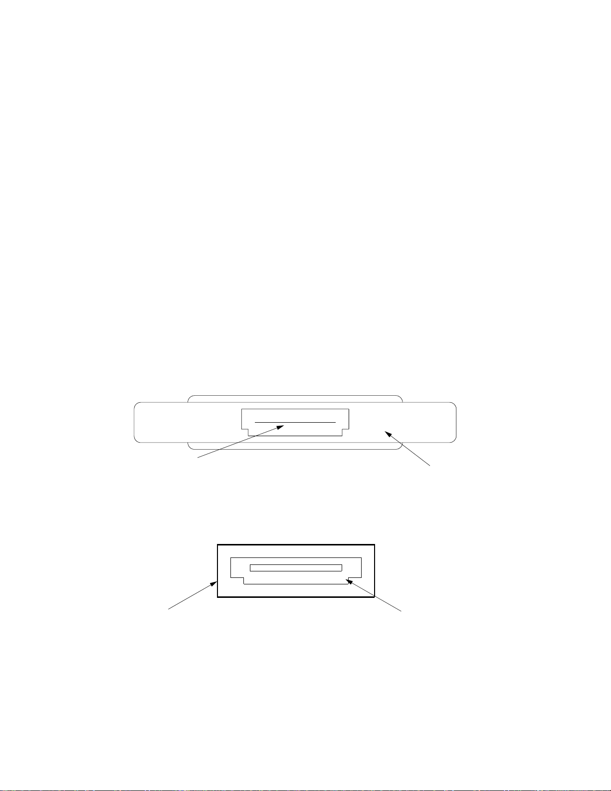
PCC-10 Laptop Network Card Electrical Interface
This section provides information about the electrical characteristics of the PCC-10 card.
Included is an overview of the electrical design of the interface for the external transceivers
and details about connecting the card's internal FT-10 compatible transceiver to a network.
Network Port
The PCC-10 has a 15-pin network port connector for interfacing with a free topology or link
power channel, and for connecting external transceiver pods.
Figure 1.1 shows the numbering scheme of the 15-pin Hirose male connector on the PCC-10
card. The top of the the PCC-10 card is the side with the product label. Figure 1.2 shows the
pin-out of the mating female Hirose NX30TA-15PAA connector to which the network wiring or
transceiver pod is connected. The Hirose connector plug should be protected with a cover
(Hirose NX-15T-CV1).
Note: As listed in Table 1.1 on the next page, pins 14 and 15 of the connector are the FT-10
Network connection pins. This is where you would connect to your twisted-pair network. They
are polarity insensitive.
Top
115
Hirose Connector:
CL234-0004-5
Bottom
PCC-10 Card
Figure 1.1. PCC-10 Card Network Port Connector (not to scale)
1
Hirose Plug Cover:
NX-15T-CV1
15
Hirose Connector
Plug: NX30TA-15PAA
Figure 1.2. PCC-10 Card Network Cable Connector (not to scale)
18
Page 19

Section 1: PCC-10 Laptop PC Network Adapter Card Information
PCC-10 Laptop Network Card Electrical Interface (continued)
Cable
Connector
FT-10
Compatible
Transceiver
+5V Power
Switch and
Current Limit
Circuit
E
S
D
C
L
A
M
P
C
K
T
R
R
R
R
R
R
R
R
1
1
1
1
1
NoCon
1
1
1
15
(FT_NetA)
14
(FT_NetB)
(GND/Shield)
13
(GND/Shield)
12
(Vcc)
11
(Vcc)
10
(Buff_CP0)
9
(Buff_CP1)
8
7
(Buff_CP2)
(Buff_CP3)
6
(Buff_CP4)
5
4
NC
(~Sense_Pod_Reset)
3
2
(~Drive_Pod_Reset)
1
(~Pod_Sense)
Hirose CL234-
Figure 1.3. PCC-10 Card Network Port Electrical Interface
The R1 resistors used in the PCC-10 card buffer the CPx lines to and from the Neuron
Chip, and have a value of 82 Ohms ± 5%.
Pin Signal Type Description
1 ~Pod_Sense Digital Input Port Connection Indicator
2 ~Drive_Pod_Reset Digital Output Reset Line for External Transceiver
3 ~Sense_Pod_Reset Digital Input External Transceiver Reset Indicator
4 No Conn No connection
5 Buf_CP4 Digital Input/Output Buffered Neuron Chip CP4 Line
6 Buf_CP3 Digital Input/Output Buffered Neuron Chip CP3 Line
7 Buf_CP2 Digital Output Buffered Neuron Chip CP2 Line
8 Buf_CP1 Digital Output Buffered Neuron Chip CP1 Line
9 Buf_CP0 Digital Input Buffered Neuron Chip CP0 Line
10 Vcc Power Output +5Vdc Supply
11 Vcc Power Output +5Vdc Supply
12 GND Shield Ground
13 GND Shield Ground
14 FT_NetB FT-10 Network FT-10 Network Connection B
15 FT_NetA FT-10 Network FT-10 Network Connection A
®
3150
Table 1.1. PCC-10 Network Port Electric Interface Description
19
Page 20

Section 2: PCNSI Desktop PC Network Adapter Interface Card Information
General Information
The PCNSI Network Interface Card is a half-length ISA card that allows a desktop computer to
access a LonWorks control network for installation, configuration, monitoring, and control
functions.
®
Note: The PCNSI Network Interface Card must be used with a LonWorks
SMX compatible
transceiver in order to be able to access the network. This transceiver is not included with the
PCNSI card, and must be purchased separately and installed onto the PCNSI card. A list of
compatible transceivers is shown later in this section.
The PCNSI card includes an NSI-10 module with a Neuron® 3150 Chip, a PROM with the
NSI-10 firmware, and support circuitry for the NSI-10 interface registers and memory control.
It communicates with the attached host computer through an 8-bit bi-directional data register
and an 8-bit status/control register; a single address bit selects the appropriate register. If
desired, the host can enable interrupts on the card for a variety of status conditions. Interrupts
can be configured by software to one of six PC interrupt requests (IRQs).
PCNSI Interface Card Layout
The following figure shows the layout of the connectors and user-accessible switches and
indicators for the PCNSI Interface Card.
1
SMX-
Compatible
Transceiver
P3
1 0
S1
Service
JP1
Transceiver
Expansion
DS1
NSI-10
Module
9876543X
I/O Address
P2 P1
Figure 2.1 PCNSI Card Mechanical Layout and Interfaces
Designation Function
P1, P2 PC ISA bus connectors
P3 SMX-compatible transceiver connector
S1 I/O address selection switches
JP1 Service pin connector
DS1 Service LED
Table 2.1 PCNSI Card Interfaces
20
Page 21

Section 2: PCNSI Desktop PC Network Adapter Interface Card Information
P1 and P2 ISA Bus Connectors
The pinout of the P1 and P2 connectors is the standard pinout for the ISA bus used in
IBM-compatible PCs. The interface card must be installed in a 16-bit slot.
SMX-Compatible Transceivers
®
A transceiver daughter card conforming to the LonWorks
SMX specification must be attached
at connector P3. The SMX-compatible transceivers listed in table 2.2 are available from
Echelon®, and are suitable for use with the PCNSI card.
Product Name Echelon Model
Number
TPM/XF-78 Twisted Pair Modular Transceiver 77010
TPM/XF-1250 Twisted Pair Modular Transceiver 77030
TPM/RS485 Twisted Pair Modular Transceiver 77050
FTM-10 Free Topology Modular Transceiver 77040
PLM-10 Spread Spectrum Power Line Transceiver 77090
PLM-21 C Band Power Line Transceiver 77160
PLM-30 A Band Power Line Transceiver 77180
Table 2.2 SMX-Compatible Transceivers
Note: The Power Line Transceivers listed in the above table require an external coupling
circuit to connect to the power line medium. Packaged coupling circuits for standard AC mains
power lines should be ordered with the SMX-compatible transceivers for power line media.
P3 SMX Connector Terminal
The SMX compatible transceiver is connected to the PCNSI Interface Card at the P3
connector. The PCNSI Interface card may be operated only with an SMX-compatible
transceiver attached.
Service Pin Access
The service pin of the Neuron® Chip is accessible directly at JP1. Pin 2 of this header is
connected to the ~Service pin of the Neuron Chip, and Pin 1 is GND. Shorting Pin 1 to Pin 2
will cause the PC Interface card to generate a service pin message. If the service LED at
location DS1 is off, the PCNSI network interface is in the configured state. If the service LED is
flashing, the PCNSI is in the unconfigured state. If the service LED is continuously on, the
PCNSI is in the applicationless state, or the Neuron Chip has detected a hardware failure.
I/O Address Selection Switches
PC Interface cards occupy a block of 8 addresses in the I/O space of the host PC. The base
address of this block may be set with the DIP switches located at S1. If another device is
allocated to an address in the range of the addresses, neither device will work properly. To set
the base address of the PCNSI registers, set the switches at S1 according to bits 3 through 9
of the address. Figure 2.2 shows the relationship of the switches to selected address bits.
Setting a switch to the upper position programs a 1 (one), and the lower position programs a 0
(zero) for the corresponding address bit.
21
Page 22

Section 2: PCNSI Desktop PC Network Adapter Interface Card Information
1
0
Address bit
Figure 2.2 Setting the PCNSI Base Address with switch S1
9 8 7 6 5 4 3 X
1 1 0 1 0 1 0 X
1
0
Address bit
Figure 2.3 PCNSI Default Base Address Setting
The default assignment for the PCNSI block of addresses is 350 to 357 hex. The default switch
setting is shown in figure 2.3. The black shading indicates the switch position; the shading
shows the side that is pushed in. Always check the switch settings before installing the card, as
the switches may have inadvertantly been moved.
Address Selection Considerations
As an aid in selecting an appropriate I/O address for PC Interface cards, table 2.3 lists
commonly used I/O addresses for PC peripheral devices, as well as alternative switch settings
for S1 in the event of address conflicts. Be careful not to choose an alternate address that will
cause a conflict in your PC.
I/O Address Range Typical Use S1 Switch Settings
0000 - 01FF Reserved for PC motherboard hardware
0200 - 0207 Joystick Input 1 0 0 0 0 0 0 0
0220 - 022F Sound Controller 1 0 0 0 1 0 0 0
0278 - 027B LPT3 Parallel Port (If LPT1 & LPT2 installed) 1 0 0 1 1 1 1 0
02F8 - 02FF COM2 Serial Port 1 0 1 1 1 1 1 0
0310 - 0317 LonBuilder Interface Adapter 1 1 0 0 0 1 0 0
0320 - 0327 LonManager Protocol Analyzer 1 1 0 1 0 0 0 0
0330 - 033F MIDI Controller 1 1 0 0 1 1 0 0
0340 - 0347 PCLTA PC LonTalk Adapter 1 1 0 1 0 0 0 0
0350 - 0357 PCNSI PC Interface Card 1 1 0 1 0 1 0 0
0360 - 036B PC Network 1 1 0 1 1 0 0 0
0378 - 037B LPT2 Parallel Port (If LPT1 installed) 1 1 0 1 1 1 1 0
0388 - 038F Sound Controller 1 1 1 0 0 0 1 0
03B4 - 03BA Video Subsystem
03BC - 03BF LPT1 Parallel Port 1 1 1 0 1 1 1 1
03C0 - 03DA Video Subsystem & DAC
03F0 - 03F7 Floppy Disk Controller
03F8 - 03FF COM1 Serial Port 1 1 1 1 1 1 1 0
9 8 7 6 5 4 3 X
9876543x
Table 2.3 Typical I/O Address Usage in PC-Compatibles
22
Page 23

Section 2: PCNSI Desktop PC Network Adapter Interface Card Information
Installing the PCNSI PC Interface Card
ESD Warning: This product contains devices that are sensitive to static electricity. Before
installing or removing a PC Interface Card or the network cables, touch earth ground with your
hand to discharge any static electricity which may have accumulated.
1. Configure the jumpers on the SMX-compatible transceiver as appropriate for the
transceiver selected and the network type it will be used for.
®
For the FTM-10 Free Topology Transceiver (Echelon
model number 77040), the default
setting for the input clock jumpers at JP1 and JP2 is 10MHz, and the Free/Bus jumper at JP3
is open (termination disabled). Set the clock jumpers at JP1 and JP2 to the proper input clock
speed for your network and set the jumper at JP3 to FREE (center pin and Free pin are
jumpered) if you are using Free Topology in your network.
Refer to the documentation provided with the transceiver for proper configuration information,
or refer to the LonWorks® SMX Transceiver Installation Instructions as found on the Echelon
internet web page at http://www.echelon.com.
2. To attach an SMX-compatible transceiver to a PCNSI card, follow these steps.
• Remove the standoff, spacer, and screw attached to the transceiver front bracket.
• Remove the nut from the center threaded post on the rear bracket of the card and discard it.
• Re-install the spacer and standoff removed from the transceiver onto the threaded post.
• Align the 20-pin connector on the transceiver over the 20-pin header on the card.
• Make sure that the transceiver face-plate is aligned properly with the hole in the rear panel,
and press the connector down firmly in place.
• Re-install the screw through the SMX-compatible transceiver and into the standoff.
3. Identify a 16-bit (ISA) slot in your PC with room for a half-length card. Remove the
corresponding blank panel from the rear of your PC, saving the screw. Insert the card in the
slot, making sure that the edge connectors are fully mated, and the slot in the rear panel
mounting lug of the card is lined up with the threaded hole in the PC chassis. Replace the
screw to hold the card firmly in place.
4. Physically attach the transceiver to a LonWorks network medium. The network connectors
are transceiver-specific. Refer to the SMX transceiver installation document for more details
on attaching the transceiver to the network. If you are installing a PLM-10, PLM-20, or
PLM-30 Power Line transceiver, connect the appropriate external power line coupler
between the transceiver and the power mains.
Interrupt Request (IRQ) Setting
The PCNSI Network Interface Card requires an IRQ setting for it to operate. During setup,
choose a setting that is not being used by another device in the PC. The default setting for the
PCNSI card is IRQ 15, but you may also use IRQ 5, 9, 10, 11 or 12 if needed. The specified
IRQ must not be used by another device. If you experience problems using the network card,
try removing all other devices from the PC or changing the IRQ for the card. Table 2.4 lists
commonly used IRQs for PC peripheral devices.
23
Page 24

Section 2: PCNSI Desktop PC Network Adapter Interface Card Information
Interrupt Request Typical Use
IRQ5 LPT2 Parallel Port, Sound Cards
IRQ9 Redirected from IRQ2, LAN Adapter 1
NodeBuilder setup default
IRQ10 LonManager Protocol Analyzer driver default
IRQ11 LonManager Protocol Analyzer setup default
IRQ12 PS/2-style Mouse
IRQ15 PC LonTalk Adapter and PCNSI driver default
Table 2.4 Typical Interrupt Request Usage in PC-Compatibles
Troubleshooting the PCNSI Network Interface Card
The following is a list of common problems with the setup and use of the PCNSI card.
Addressing problems
Assigning an address is easy, although it may take several tries to find one that works.
Fortunately, there are a lot of potential addresses. Earlier in this section you will find
information about how to use the DIP switches to select an address, as well as information
about various adapters and the addresses they typically use. If you know exactly which
addresses are used in your PC, just set the DIP switches to an unused address. If the PCNSI
card does not have a unique address on the PC, the computer will attempt to communicate
with the PCNSI card incorrectly.
When the computer is booted and the driver for the PCNSI card is loaded, the PCNSI card
®
holds its Neuron
Chip reset after power-on. The driver will configure the Neuron Chip's clock
rate and unreset the Neuron Chip. The Service LED should flash several times. The key for
troubleshooting is whether the Service LED ever goes off after being turned on. If it ever goes
off, it means that the card is being addressed; software is sending out I/O writes that the card
is seeing.
If the Service LED does not behave as indicated, you may have an address conflict. With the
PC powered down, try setting the address DIP switches on the PCNSI card to a different
address, and reboot the computer checking for proper behavior. Watch the Service LED at
DS1. It should be off until the driver loads. It should flash briefly several times and stay off, or
flash briefly several times and then flash at 0.5Hz. If it does not do either of these things, the
card is not being addressed.
If you are still having problems using the PCNSI card, even though it seems that it is being
addressed properly by the PC, you may have two cards with the same address. If another card
on your system stops working when the PCNSI is at this address, then an address conflict is
most likely. The easiest thing to do is to change the address on the PCNSI card; this avoids
having to change the address of the other card. Refer to the information located earlier in this
section about changing the address of the PCNSI card using DIP switch S1.
24
Page 25

Section 2: PCNSI Desktop PC Network Adapter Interface Card Information
Assigning a Unique Interrupt (IRQ)
If you know exactly which interrupts are used in your PC, just set the interrupt of the PCNSI
card to an unused IRQ. The PCNSI card can be configured to use IRQ5, IRQ9, IRQ10, IRQ11,
IRQ12 or IRQ15. The default is IRQ15. If you are low on available IRQs, you can use the LPT2
interrupt request, IRQ5, provided that you do not have two printers.
If you have tried all six interrupts, and none work, remove as many other I/O cards as possible
from your PC and try again. If you find an interrupt that works, try reassigning or disabling the
interrupt of the conflicting card.
If you have two devices in your PC with the same IRQ selected, your PC will either lock up at
boot, or the two devices affected will not operate properly. Verify that each device in your PC is
using a unique IRQ.
®
Windows
95 allows you to check your IRQ assignments and to check for conflicts using
Control Panel. Double-click on My Computer, Control Panel, System. When the System
Properties window opens, click on the Device Manager tab. Make sure that "Computer" at the
top of the list is highlighted, and that the "View devices by type" option is selected. Click the
Properties button. This will open the Computer Properties window. Make sure that the "Interrupt Request (IRQ)" option is selected. Listed will be all of your devices and the IRQs that they
are assigned.
If you close the Computer Properties window and go back to the System Properties window,
you can select the device that you suspect a conflict with, and then click the Properties button.
This will open a window with the information about that device. There are three tabs; General,
Driver, and Resources. Click on the Resources tab. You will see a window called Resource
settings. Listed will be the Interrupt Request (IRQ) and the Input/Output Range (address).
Further down is a box called the Conflicting Device List. If there are any conflicts, they will be
listed here. If there are no conflicts with the device, you will see the message "No conflicts".
If you are having trouble resolving a conflict, you can access Help by clicking on the Start
button on the task bar, and when the menu pops up, select "Help". The Help topics window will
open with the index tab selected. Type a keyword to search for into the window, such as
"hardware conflict". This will bring up an index topic related to resolving hardware conflicts. In
this case, it is "hardware conflict troubleshooter". Click the Display button, and a window with
the Hardware Conflict Troubleshooter will open. This will step you through the process of
resolving a hardware conflict on your PC.
25
Page 26

Section 2: PCNSI Desktop PC Network Adapter Interface Card Information
Diagnostics
®
A number of diagnostic and testing services are provided by the LonWorks
NI Control Panel.
Double-click on My Computer, Control Panel, and then LonWorks NI.This will open the PCLTA/
PCNSI Network Interface Configuration dialog box. Clicking the diagnostics button displays the
Diagnostics dialog box. This dialog box contains buttons for the diagnostic commands and
displays the version number and current status of the device driver. If no adapter is installed in
an ISA-bus slot, the Diagnostics window will display "no driver found". The OK button closes
the dialog box.
The Test button retrieves status and error counts from the adapter. In the box you will see
displayed CRC Errors, TX Timeouts, Lost (App) Messages, Missed (Net) Messages, the Node
State (Configured, Unconfigured, or Applicationless), the number of most recent errors, and
the Reset Cause (reset cause for the Neuron® Chip in the adapter, internal or external).
The Service button causes the adapter to broadcast a service pin message on the network.
The service pin message will not be sent if the adapter is in the post-reset flush state.
The Reset button causes a reset of the Neuron Chip in the adapter, but it does not clear the
Neuron Chip's system image.
The Comm Button
The Comm button verifies communications between the adapter and another node on the
network. This can be a very useful troubleshooting tool. When this function is chosen, a dialog
will appear asking for confirmation of this command, as follows:
This procedure will configure the Network Interface for a zero-length
domain if it is not already configured. Do you want to proceed?
Choosing OK causes the Control Panel to first check the network interface for the configured
state. If it is already in the configured state, it will not be modified further. If it is not in the
configured state, it will install the network interface with a zero-length domain on index 0, a
subnet of 1, and a node ID of 126, and then change its state to configured.
Once the node is in the configured state, the control panel enters the receive/ready state and
displays the following message while waiting for a service pin message from another node on
the network:
Now waiting for a service pin message.
When the service pin is activated on the other node and the service pin message is received,
the control panel sends a request/response diagnostic message to the node that sent the
service pin message. It will repeat this message, referred to as a "ping", once per second until
either the OK or the Quit button is chosen (the Quit button appears in place of the Comm
button).
This series of tests confirms that the adapter can be configured and can communicate with a
node on the network.
26
Page 27

Section 2: PCNSI Desktop PC Network Adapter Interface Card Information
The Comm Button (continued)
The Comm function is intended to eliminate the adapter, the card drivers, the network
connection, the hardware of the other node, and the topology configuration from the list of
possible problem points or points of failure during network troubleshooting. It does not eliminate the possibility that the wrong type of cable medium has been used. Be sure that the cable
type selected is suitable for use in the intended channel topology.
The Comm function also does not eliminate the possibility of poor network termination.
The network wiring may work for this test but may fail if multiple nodes are communicating.
Be sure to verify proper termination when troubleshooting communication problems.
This feature was not designed to work across routers.
Common Resource Problems
The following situations produce an additional drain on system resources that may be hard to
manage. Conflicts arising from these situations can generally be resolved by selectively
disabling devices to free up the required resources.
• COM ports that may not have a connector, but are consuming resources and cannot be
disabled through the BIOS.
• Unused IDE controllers that cannot be disabled through the BIOS.
• Unused/nonexistent PS/2 mouse ports.
• Sound cards that support both 8-bit and 16-bit compatability modes, consuming two IRQs.
An additional problem often associated with sound cards is the improper reporting of I/O
resource usage. This problem may be recognized by examining a device's I/O address allocation for unusual one-byte assignments (since devices typically use more). For example, if a
device's stated I/O range is 0x201-0x201 but its actual range is 0x201-0x204, a conflict will
occur if the adapter is assigned an I/O range of 0x204-0x207. If this problem is suspected,
manually move the adapter's I/O range to a safer location to prevent I/O overlap.
27
Page 28

Section 3: FTT-10A Network Information
General Information
®
uses the FTT-10A Free Topology Network Configuration along with the PCC-10 Type II
Bose
card with FTT-10A transceiver on-board for Laptop PCs, and the PCNSI ISA-bus half-length
network card with an FTT-10A transceiver on-board for use with the Entero™ audio control
network. Each LonWorks® device used in an Entero audio control network uses the Neuron
3150 Chip. The Neuron 3120 Chip is not used in Entero.
®
Clock
Circuit
XCVR.
Service
LED
MAC
CPU
Lines
Reset
Circuit
Net
CPU
Power Supply
Appl.
CPU
I/O LinesCP
Internal Memory
Twisted-pair
Network
Address Lines: A0-A15
Data Lines: D0-D7
Control Lines: ~E, R/~W
LonWorks
Device
External Memory (3150 Chip Only)
Figure 3.1 Block Diagram of a LonWorks Device on a Twisted-Pair Network
The three CPUs interleave accesses to memory for instruction execution and memory read/
write operations. The Neuron 3120 Chip runs completely from internal memory, while the
Neuron 3150 runs from both internal and external memory. For convenience, the division of
tasks among the three CPUs is described briefly here:
MAC CPU: The Media Access Control CPU is responsible for interfacing with the
transceiver. It handles all physical layer transmitting and receiving of
packets, including the p-CSMA algorithm.
Network CPU: The network processor manages the incoming and outgoing message
buffers. It is also responsible for managing the software timers.
Application CPU: The Application processor runs the Neuron C application program.
When a non-MIP device is in the Unconfigured state, the Neuron C
application program does not execute. A non-MIP device must be in
the Configured state for the application to run.
28
Page 29

Section 3: FTT-10A Network Information
General Information (continued)
Configuration States of a Device
A LonWorks device can be in one of the following three firmware states:
1. Applicationless: Only communication parameters are loaded into the device's internal
EEPROM. The Service LED remains continuously ON in this state.
2. Unconfigured: In addition to its communication parameters, the device contains an
application program. The Service LED blinks about once every two
seconds in this state. The device does not yet have information about
its network configuration, such as its network address, network
variable binding information, etc. A non-MIP device does not execute
it's Neuron
®
C application program while it remains in this state. A MIP
device does execute its MIP application when in an Unconfigured
state, so that it can communicate with the MIP's host processor.
3. Configured: In addition to the information from the Unconfigured state, a
Configured device has been assigned its network addresses and
binding information. The Service LED is generally OFF in the
Configured state, and the Neuron C application program is running.
Network Overview
The FTT-10A Free Topology Twisted Pair Transceiver provides a simple, cost effective method
of adding a LonWorks transceiver to any Neuron Chip-based control system. A replacement
for the popular FTT-10 transceiver, the FTT-10A transceiver supports polarity insensitive, free
topology wiring, relieving the installer from using a bus topology. Star, bus, and loop wiring are
all supported by this architecture.
Free topology wiring reduces the time and expense of system installation by allowing the
wiring to be installed in the most expeditious manner. It also simplifies network expansion by
eliminating restrictions on wire routing, splicing, and node placement. FTT-10A transceivers
can be located at any point along the network wiring. Figure 3.2 shows an example of Free
Topology.
Termination
Figure 3.2 FFT-10A Free Topology Network Diagram
29
Page 30

Section 3: FTT-10A Network Information
System Performance and Cable Selection
TP/FT-10 network system and transmission specifications are outlined on the following pages.
Both of these specifications must be met to ensure proper operation.
The system designer may choose a variety of cables, depending on cost, availability, and
performance. Performance may vary with cable type. The transmission specification depends
on such factors as resistance, mutual capacitance, and the velocity of propagation. Currently,
Echelon has documented system performance on the cable types shown in table 3.1.
Cable Type Wire diameter/
Belden 85102, single
AWG
1.3mm/16 28 56 62
R
loop
Ohms/km
Capacitance
nF/km
twisted pair, stranded
19/29, unshielded, 150°C
Belden 8471, single
1.3mm/16 28 72 55
twisted pair, stranded
19/29, unshielded, 60°C
Level IV 22 AWG, twisted
0.65mm/22 106 49 67
pair, typically solid and
unshielded
JY (st) Y 2x2x0.8, 4-wire
0.8mm/20.4 73 98 41
helical twist, solid,
shielded
TIA568A Category 5 24
0.51mm/24 168 46 58
AWG, twisted pair
Table 3.1 Cable Types and Typical Parameters
If a shielded cable is used, the shield should be connected to earth ground via a single
470 kOhm, 1/4 Watt, ≤10%, metal film resistor to prevent static charge build-up.
®
Bose
recommends the use of TIA568A Category 5 wiring for use in the Entero™ System
network.
V
prop
% of c
System Specifications
Up to 64 FFT-10/FFT-10A transceivers are allowed per network segment.
LPT-10 transceivers may be used on network segments with FFT-10/FFT-10A transceivers,
but are subject to additional constraints, particularly on distance. See the Echelon® LPT-10
Users Guide for more information. It is available on-line at the Echelon web page at http://
www.echelon.com.
The average temperature of the wire must not exceed +55°C, although individual segments of
wire may be subjected to as much as 85°C.
30
Page 31

Section 3: FFT-10A Network Information
Transmission Specifications
The free topology transmission specification includes two components which must both be met
for proper system operation. The distance from each transceiver to all other transceivers and
to the termination (including the LPI-10 termination, if used) must not exceed the maximum
node-to-node distance. If multiple paths exist, e.g., a loop topology, then the longest path
should be used for the calculations. The maximum total wire length is the total amount of wire
connected per segment. See table 3.2 for these specifications.
Cable Type Maximum node-to-node
distance
Maximum total wire
length
Belden 85102 500 meters 500 meters
Belden 8471 400 meters 500 meters
Level IV 22 AWG 400 meters 500 meters
JY (st) Y 2x2x0.8 320 meters 500 meters
TIA568A Category 5 250 meters 450 meters
Table 3.2 Free Topology Network Specifications
Cable Termination
The FFT-10 network segment requires termination for proper data transmission performance.
A total termination impedance of approximately 52.3 Ohms is required.
In a Free Topology segment, only one termination is required, and it may be placed anywhere
on the segment. There are two choices for the termination.
1. Resistor, 105 Ohms ± 1%, 1/8W, connected across the twisted pair wires.
2. LPI-10 Link Power Interface, with jumper at "2 CPLR" setting.
31
Page 32

Section 3: FTT-10A Network Information
Troubleshooting an FFT-10A Network
Noise on Real-World Networks
When a network is installed in a real-world environment (as opposed to the development lab
environment), it is exposed to several noise sources that can make network communications
more difficult.
Power Line Noise and Ground Shifts: The "Safety" or "Earth" ground difference in voltage can
have a DC component, but more often the voltage varies at the power line rate (50 Hz or 60
Hz), with an amplitude that can reach many 10's of volts, or higher. DC shifts and power line
frequency noise are naturally rejected by the transformer-coupled transceivers in FFT-10
devices. Link Power LPT-10 devices are required to be "floating" with respect to their local
Earth ground reference.
High Frequency Burst Noise: When the network cable is run near DC motors or other sources
of burst noise, common mode voltage noise can be coupled into the twisted pair. Even though
this burst noise has frequency components within the communication band of the network, the
common-mode rejection of the coupling transformer used in the FTT-10 transceiver is usually
sufficient to prevent significant impairment of communication.
Common Network Wiring Problems
Symptom Possible Cause
Devices work fine on a
small network, but
communication fails on a
large network installation.
The network wire,
terminations, etc. all seem to
be within Echelon's design
rules, and the network
management software
seems to be configuring the
devices correctly, but some
device communications are
still unreliable.
1. Verify that the rules for wire type, length, termination, etc. given in
the Transceiver's Users Guides have been followed.
2. When communication on a large network is a problem, suspect bad
connections, bad terminations, extra capacitive loading of some kind
(like transient protection devices not listed in the User's Guides), or
noise sources coupling into the network. Also make sure that the
network addressing and configuration of the devices is correct.
1. If a few devices have communication problems no matter where
they are moved on the network, suspect a bad network connector or
a bad device. If devices have problems only when moved to certain
spots in the network, suspect transmission line problems (like a
broken termination), or point noise sources near the failure spots.
2. If a hardware reason for the failures is not apparent, use a Protocol
Analyzer to watch network traffic for addressing anomalies that might
indicate network management problems.
32
Page 33

Section 3: FTT-10A Network Information
Common Problems with FTT Networks
Symptom Possible Cause
A device cannot
communicate on an FTT
network.
The device can transmit, but
not receive; for example,
LonBuilder tool install
succeeds, but nothing else
works.
The device communicates
fine on short networks, but
does not communicate on a
"full-size" network
installation.
First make sure that the wire, connections, and terminations are
correct. Then use Service pin presses to generate transmit packets,
so that the CP line waveforms can be checked. Another device on
the network can be used to generate incoming traffic to the device
under test in order to check the CP line waveforms in receive mode.
Finally, the analog waveforms on the network can be checked for
clues about the lost communication.
Suspect an incorrect clock configuration for an FTT-10:
- Check CSO and TXD/CS1 connections for FTT-10.
- Reset the device by manually grounding the reset line. If the device
recovers, suspect an incorrect reset circuit or transient protection
circuit implementation. See the FTT-10 User's Guide for correct
circuit implementation.
An incorrect clock configuration on the FTT-10's CSO and CS1 pins
will usually result in the FTT-10 transmitting a very distorted
waveform, even into a small, lightly-loaded network. An FTT-10 with
an incorrect clock configuration will not receive packets from the
network.
Make sure that the total wire length and type agree with the
specifications in the FTT User's Guide. Suspect an overloaded
network, or incorrect wire substitution.
Check the termination(s). Incorrect or broken terminations will make
communication integrity dependent upon a device's position on the
network.
When attempting to transmit
a packet, the device's CP
lines do not behave
correctly.
An FTT-10 device that uses
a DC-DC converter power
supply has a high CRC
error rate, and has trouble
receiving packets on
heavily loaded networks.
Check the devices to be sure that no extra capacitance is being
connected to the network other than the standard FTT circuit. A
common error is to add high-capacitance transient protection devices
(like zeners) across the network connection.
The FTT-10 uses Single Ended mode for the CP lines CPO, CP1
and CP2 are RXD, TXD, and TXEN, respectively. If the device is
incorrectly configured for differential mode or special purpose mode,
the CP lines will not function correctly for controlling the FTT-10.
Suspect that DC-DC switching noise is interfering with the 78kbps
communication band of the FTT-10. Check the switching frequency of
the DC-DC; if it is 1MHz, it is not likely the source of the problem. If it
is 50-100kHz, interference with communication is possible. The FTT10 has good power supply rejection in the communication band, so
the most likely noise coupling mechanism is magnetic. Make sure the
DC-DC switching inductor is not adjacent to the FTT-10 transceiver
and its transformer. The transformer used on the FTT-10 rejects
magnetic noise coupling well, so the DC-DC inductor would need to
be fairly close to cause a problem. Try re-orienting or moving the DCDC inductor to see if the comm problem goes away.
33
Page 34

Section 4: Echelon® Model 71000 Router Information
Introduction
LonWorks
®
routers connect two communications channels, and route LonTalk® messages
between them. They support the installation of both small and large networks with dozens
to thousands of nodes.
The following figure illustrates a typical installation with free topology, power line, and 78kbps
bus topology channels connected to a 1.25Mbps backbone twisted pair channel using three
routers. Because of the routers, the applications on all six nodes in this example can
communicate transparently as if they were installed on a common channel.
TP/XF-1250 Backbone Channel
TP/XF-1250 to
TP/FT-10 Router
TP/FT-10 Channel 1
TP/XF-1250 to
PL-10 Router
PL-10 Channel 2 TP/XF-78 Channel 3
TP/XF-1250 to
TP/XF-78 Router
Node 1 Node 2 Node 3 Node 4 Node 5 Node 6
Figure 4.1 Sample Router Installation
Routers are used to:
•
Extend the limits of a single channel.
A router may be used to add a channel to a LonWorks
network to support additional nodes or extend the maximum channel length. Multiple routers
may be added, depending on the capacity or distance needed.
•
Interface different communication media, or bit rates, in a LonWorks network.
For example,
it may be desirable to trade data rate for distance on portions of the network, or to use a
1.25Mbps backbone twisted pair channel to connect several 78bps free topology and link
power channels. Alternitively, it may be desirable to use power line for a portion of the
network where the nodes are subject to frequent physical relocation, or if cable installation
is difficult. In all of these cases, a router must be used to connect to the dissimilar LonWorks
channels.
•
Enhance the reliability of the LonWorks network.
The two channels connected to a router
are physically isolated, so a failure on one channel does not affect the other. For example, in
an industrial control network, isolation among connected cells may be desirable to prevent a
failure in a single cell from bringing down multiple cells. This would be acheived by
dedicating channels to individual cells and isolating them from one another with routers.
34
Page 35

Section 4: Echelon® Model 71000 Router Information
Introduction (continued)
Improve overall network performance.
•
Routers can be used to isolate traffic within sub
systems. For example, in a cluster of industrial cells, most of the communications may be
with nodes within cells rather than across cells. Use of intelligent routers across cells will
avoid forwarding messages addressed to nodes within a cell, thus increasing the capacity
and decreasing the response time of the overall network.
The use of routers across channels is transparent to the application programs within nodes.
Thus, application development can be done independantly, without knowledge of the workings
of the routers. Routers need to be taken into account only when determining the network
image of a node. If a node is moved from one channel to another, only the network image must
be changed. Network images are managed by a network services tool such as the
LonManager® LonMaker® Installation Tool.
LonWorks® routers are offered in a variety of options so they can be tailored for specific uses.
Options include the following:
•
Integration.
Router components are available for embedding in OEM products. An RTR-10
router and two transceiver modules, one to handle each of two channels connected by the
router, may be mounted on a motherboard, along with a power supply and two network
connectors. This sub-assembly constitutes a custom router. It can be packaged in an
enclosure to meet unique form factor and environmental requirements. Depending on the
application, the package may contain a single router sub-assembly, or may include other
application-specific hardware. See figure 4.2 for a block diagram of a router based on the
RTR-10 router. Multiple routers may be packaged together for some applications, e.g., a
backbone connecting multiple channels.
Packaged routers are also available from Echelon. They are FCC- and VDE-certified to
comply with conducted and radiated emmissions specifications and UL-certified for safety,
with optional wall-mounted power supplies. These routers eliminate the need to build
hardware and obtain the necessary electrical interference and safety certifications. Thus,
they allow direct, off-the-shelf integration into the user's LonWorks network.
Service Button/LEDs
Power
Supply
RTR-10 Router Core Module
Side A
Transceiver
Side A Network
Connector
Side B
Transceiver
Side B Network
Connector
Figure 4.2 Router Assembly Using the Router Core Module
35
Page 36

Section 4: Echelon® Model 71000 Router Information
•
Routing Algorithm.
learning router, bridge, or repeater. These options allow system performance to be traded
for ease of installation. Configured and learning routers fall into a class of routers referred to
as intelligent routers, which use routing intelligence to selectively forward messages based
on the destination address. A bridge forwards all packets that match its domain(s).
A repeater forwards all valid packets.
A network services tool such as the LonMaker® Installation Tool is used to select the routing
algorithm and calculate network topology, as well as layer 4 timing parameters. Both sides of
a router must use the same algorithm. LonBuilder®, LonMaker, or a tool based on the
LonManager® API is required to install a configured router.
Packaged Router Overview
This section provides an overview of the Model 71000 LonWorks Router Hardware.
Mechanical Description
Routers can use one of four routing algorithms: configured router,
Figure 4.3 Echelon Model 71000 Router Diagram
36
Page 37

Section 4: Echelon
Switches, Indicators, and Connectors
Table 4.1 describes the function of router switches, indicators, and connectors.
®
Model 71000 Router Information
Interface Function
Service
Request
Pressing this switch grounds the service pin to both sides of the router.
When this switch is pressed, both Service LEDs should light to maximum
intensity. This action generates service request messages from each side
of the router.
Service 1 (Yellow LED) When the service request switch is being pressed, this LED
is on at maximum intensity. If the service request switch is not being
pressed, then the LED indicates the following:
ON: An unrecovered error has been detected on side one.
BLINKING: Side one unconfigured; routing tables or routing node address
assignment have not been loaded.
OFF: Side one configured.
Power On (Green LED) Indicates that power is being supplied to the router. Does not
necessarily indicate that the power supply voltage is within tolerance.
Status (Green LED) Flickers when a packet is being forwarded in either direction.
The rate of flashing can be used as a rough indicator of router activity level.
Service 2 (Yellow LED) When the service request switch is being pressed, this LED
is on at maximum intensity. If the service request switch is not being
pressed, then the LED indicates the following:
ON: An unrecovered error has been detected on side two.
BLINKING: Side two unconfigured; routing tables or routing node address
assignment have not been loaded.
OFF: Side two configured.
Power Input connector for power supply.
Net 1 RJ-45 modular connector for connecting side one of the router to a
twisted-pair channel.
Net 2 RJ-45 modular connector for connecting side two of the router to a
twisted-pair channel.
Table 4.1 Model 71000 Router Interfaces
Installing a Router
To install a LonWorks
1. Define a network topology.
2. Physically attach the router to a LonWorks network.
3. Connect power to the router.
4. Logically install the router on the network.
5. Test the router installation.
®
Router, follow these steps:
37
Page 38

®
Section 4: Echelon
Model 71000 Router Information
These steps are described in more detail in the following sections.
Defining a Network Topology
There are many possible network topologies when using routers. The first rule for initial integration is that if a network services tool is used for installation, then a physical or logical path
must exist between the network services tool and the router targeted for installation. A physical
path is created if the network services tool is connected to the same media as one side of the
LonWorks® Router. A logical path is created if one or more active installed routers exist
between the LonWorks Router and the network services tool. The routers creating the logical
path may be LonWorks Routers, LonBuilder® Routers, or custom routers based on the RTR-10
Router Core Module. The routers in the logical path must be installed, loaded, and online
before the new router may be added to the network.
When installing routers on a development network, the LonBuilder or LonManager® Protocol
Analyzer can be used to verify that a path exists to a router to be installed. To verify the existence of a logical path, press the service switch of a powered router. If a physical or logical path
to the protocol analyzer exists, this action will increment the packets received count. A detailed
view of the packet log resulting from the previous action will show a code of 0x7F; this is the
message code for an unsolicited service pin message.
Attaching the Router to a Network
The next step in installation is to physically attach the router to two channels in a LonWorks
network. It is important to insure that each channel has only one transceiver type attached to it.
Mixing signals from different transceivers will defeat the collision avoidance algorithms and
therefore severely degrade network performance.
The router can be connected to the bus using a 24 AWG stub with an RJ-45 connector on one
end and flying leads on the other. For free topology and link power channels, the 24 AWG
stubs must be limited to 1 ft. (0.3 m), with no more than five 24 AWG stubs per segment.
Longer stubs can be used by splicing the 24 AWG stub to the heavier gauge wire specified in
the free topology and link power user's guides.
The pin-out for the RJ-45 connector as used on the Model 71000 Router is numbered from 1
through 8, sequentially from left to right when viewed from the outside of the connector. See
figure 4.4. Pins 1 and 2 are the network connections, pins 3 through 6 are not connected, pin 7
is connected to the signal ground through a 100 Ohm resistor (used for TP/RS485 only), and
pin 8 is reserved.
1 8
Figure 4.4. RJ-45 Connector Pin-out Diagram
38
Page 39

r
Section 4: Echelon® Model 71000 Router Information
Attaching the Router to a Network (continued)
The connection between pin 7 and local signal ground provides a means for reducing
common-mode voltages between nodes on a TP/RS485 channel. In the typical case, pin 7
would be connected to either earth ground or to a separate network ground. A network ground
can be provided by a third conductor or cable shield in the twisted pair cable. Two 100 Ohm
resistors within the router are used to limit circulating current when a network ground is used.
For safety, the 100 Ohm resistors are actually thermistors which change to a high impedance if
overloaded.
Proper electrical termination is essential for each twisted pair channel. Failure to terminate the
network will degrade performance and in some cases eliminate a node's ability to communicate with other nodes. For TP/XF and TP/RS485 channels, the terminator circuits shown in
figure 4.5 should be used. The terminators provided with the LonBuilder
®
and NodeBuilder™
TP/XF kits may also be used.
All resistors metal film
All capacitors metal/polyeste
59 Ohms
1%
.15 uF
10%
120 Ohms
340 Ohms
1%
102 Ohms
1%
TP/XF-78, TP/XF-1250,
and TP/RS485
.33 uF
10%
Alternate for TP/RS485 only
5%
Figure 4.5 Network Termination Circuits for TP/XF and TP/RS485 Networks
Connecting Power
Once the router is physically attached to the desired channels, power must be supplied. Power
is supplied to the Model 71000 LonWorks® Router via the power input connector on the side of
the router. The router may be ordered with a wall-mount power supply, or you can create your
own. Four power supply options are available for the router, depending on the country for
which the router is intended. These are USA/Canada, United Kingdom, Continental Europe,
and Japan. The output voltage is a nominal +9Vdc at 500mA. The following table describes the
basic characteristics of the four power supply types.
39
Page 40

Section 4: Echelon® Model 71000 Router Information
Connecting Power (continued)
Country or
Region
USA/Canada 120 VAC 108-132 VAC 60 Hz 2-prong, NEMA
Nominal
Input
Voltage
Input Range
Nominal ± 10%
Frequency Input
Connector
Echelon
Model
Number
78010
1-15P
Japan 100 VAC 90-110 VAC 50/60 Hz 2-prong, NEMA
78040
1-15P
U.K. 240 VAC 216-264 VAC 50 Hz 3-prong, U.K.
78030
Plug
Europe 220 VAC 198-242 VAC 50 Hz 2-prong, Euro
78020
Plug
Table 4.2 Power Supply Characteristics
Any power supply may be used for the Model 71000 LonWorks
®
Router that meets the
following specifications: the power input to the router must be +9 to 15 VDC at 500mA,
negative tip, outer barrel positive. The connector is a standard female DC power plug with a
2.1mm inside diameter and a 5.5mm outside diameter. LZR Electronics part number HP-114A,
or Radio Shack catalog number 274-1569 will comply.
When power is connected to a router, the Status and Service LEDs will change state as
follows:
• For an unconfigured router, the Status LED should flash once and stay off. The Service 1
and 2 LEDs will flash about once every two seconds.
• For a configured router, the Status and Service 1 and 2 LEDs should flash once and stay off.
Installing the Router on a Network
Once the router is physically attached to a network, and powered up, it must be logically
installed on the network. A router may be installed using a network services tool such as the
LonMaker Installation Tool or the LonBuilder
tool based on the LonManager® API.
Testing Router Installation
Once the router has been installed, the Query Status network diagnostic message can be used
to ensure that it is operational. If no response is received, all intermediate routers should be
queried to determine where the fault occurred. If the router has been installed with LonMaker,
the Test command can be used to query router status.
®
Network Manager, or a custom network services
40
Page 41

®
Section 4: Echelon
Model 71000 Router Information
Building a Router Mounting Bracket
®
The Model 71000 LonWorks
Router may be wall-mounted using a custom mounting bracket.
The following figure is a mechanical drawing of a suitable bracket that can be constructed by
any sheet-metal subcontractor. All measurements are in inches.
3.00
6.46 5.26
.60
2.00
4x R.25
0.6 THICK REF.
3M 4014 DBL SIDE
FOAM TAPE 0.6 THK
4x 0.190 THRU
.98
2.00 SQ.
1.37
1.28
3.90
Figure 4.6 Model 71000 Routing Mounting Bracket Fabrication Diagram
41
Page 42

Section 5. K11 and K12 Keypad Information
General Information
The K11 and K12 Keypads are networked, push-button interfaces to the Entero™ System.
The pushbuttons located on the interfaces can be programmed to control any element of the
system, from selecting a new audio source to invoking a completely new scene; including
equalization, gain, etc. LEDs on the keypads provide feedback to the user. Since the keypads
are networked devices, they are easy to install, can control any number of amplifiers and
signal processors, and their functionality can be reprogrammed at any time.
Pushbuttons
(up to 16)
LEDs
(up to 16)
K11 or K12
Keypad
Network
Audio Signal Processor
Graphical
User
Interface
Figure 5.1 K11 and K12 Keypads for the Entero System
The K11 and K12 Keypads consist of two parts: the metal-enclosed base module which
contains the electronics, and the keypad module which is customized to each installation.
The K11 and K12 Keypads provide a simple-to-use interface to the Entero system. Using this
interface, the numerous controls, most of which are typically set once by the installer, are
hidden from the user and only user-required functions are made available either in the
Graphical User Interface or the K11 or K12 Keypad.
The K11 and K12 Keypads provides zone control in multi-zone systems. Because of its
modularity, most Entero systems will have multiple zones. The K11 and K12 Keypads provide
a means of individual control for each zone.
The K11 and K12 Keypads are easy to "program", or set up from the Graphical User Interface,
and are customizable for each installation.
The base module of the K11 and K12 Keypads are designed to fit in a standard 1-gang
electrical box. Its is not visible to the user and has no styling requirements.
The keypad attaches to the base module, and fits within a Decora switch cover. Different
keypad modules are available with either 11 (K11) or 12 (K12) buttons. Depending upon the
keypad type, 0, 4, 6 or 8 buttons can have LEDs. All keypad modules are white and will be
used with a white Decora switch cover. The switch cover is silkscreened with a gray Bose logo.
42
Page 43

Section 5. K11 and K12 Keypad Information
Pushbuttons
Keypad
Module
Decora
Switch
Cover
Design Features
• Removable keypad
• Customizable keycaps
• Network interface
• Programmable buttons
• Programmable LEDs
• Centralized power supply
LEDs
Figure 5.2 K12 Keypad and Cover
Removable keypad
The removable keypad allows the installer to select a keypad that is appropriate for the
installation. Two general styles of keypads are available: 12 buttons located in 6 rows of two
buttons, and an 11 button version with 3 rows of 2 buttons plus a 5 button cursor layout: up,
down, left, right, and center. Within these two styles, various numbers of LEDs can be selected: none, 4, 6, or 8.
Customizable keycaps
The keypad consists of an housing, an elastomer conductive key holder, and replaceable
keycaps. Custom pad-printed keycaps can be ordered to suit the installation. For example, a
church might have custom buttons with labels such as "CHOIR", "PULPIT", "WEDDING", etc.
Network interface
The network interface provides the means of connecting the K11 and K12 Keypads to the
other products in an Entero™ installation. The interface contains a free-topology FT-10A
transceiver, making it physically compatible with other Entero products. Wiring the interface is
simplified because it can be attached anywhere a network connection exists. The interface
contains a 4-position screw-terminal block at the rear of the base module for connecting to the
network and power supply. The network and power wires will be brought through the electrical
box and attached to these terminals.
43
Page 44

Section 5. K11 and K12 Keypad Information
Programmable buttons
Each button on the K11 or K12 Keypad is programmable to perform any function in the system.
Example functions include: raise and lower volume, select sources, select a new EQ, etc.
Complete scenes, which may consist of tens of settings, can also be invoked by a single
button press. The Graphical User Interface is used to program the function of each button.
Programmable LEDs
Each LED can be programmed to reflect a state, momentary key press, or status such as a
network error. When used as a state indicator, the LED will usually be associated with the key
that invokes that state or mode. When a new mode is invoked, e.g., from a different button, the
previous mode LED will be turned off. The mode LED will also be turned off if one of the
parameters that makes up the mode is changed.
When programmed for momentary action, the LED illuminates only to indicate an action or
mode was invoked.
When programmed for status indication, the LED illuminates to indicate a network status such
as an error. The LED stays illuminated until cleared locally (by a combination of key presses)
or from the network.
Centralized Power Supply
The K11 and K12 Keypad use less than 200mA and can be powered from a centralized power
supply. The power supply will typically be located in an equipment area where the network
connection is also made. Multiple interfaces can share a single supply, reducing the system
costs.
For installations using CAT 5 wire, power can be provided on any of the 3 remaining pairs. The
size of the supply and the gauge of the wire required are functions of the number of interfaces
needed and the total distance of wire between the interfaces and power supply.
44
Page 45

Section 5. K11 and K12 Keypad Information
Product Description
Size: 4.1"H x 1.85"W x 2.4"D (including keypad)
Weight: 0.5 lb
Enclosure: Base module: steel; keypad: plastic
Service LED
Service
Pushbutton
Header 9 x 2
1.74"
4.23"
Figure 5.3 K11 and K12 Keypad Base Module Front View (without keypad)
Service Pin
The service pin pushbutton is located on the front panel behind the keypad. You must remove
the Decora switch cover and the keypad module to access the service pin. Since this button is
only used during installation, its location behind the keypad doesn't present a problem.
Service LED
The service LED is located on the front panel directly above the service pin. You must remove
the Decora switch cover and the keypad module to see the service LED. Since this LED is
used only during installation and troubleshooting, its location behind the keypad doesn't
present a problem.
Keypad Connector
The base module contains a header socket located on the front of the base module for
connecting to the keypad module. The header socket accomodates the 2 x 9, 0.25" sq. post
header of the keypad module.
45
Page 46

Section 5. K11 and K12 Keypad Information
Network and DC Power Connector
Located at the bottom of the base module, the network and dc power connector is a 4-pin
header connector accessible through the base module enclosure. The header is compatible
with a 5.08mm spacing connector terminal block plug. The connections are labeled +12VDC,
GND, NET1, and NET2. The K11 and K12 Keypads connect to the network using a built-in
®
Echelon
FTT-10A free topology transceiver. This transceiver consists of an isolation transformer that is integrated with a 78kbps differential Manchester coded communication transceiver. The Interface is connected to the network by it's 2-wire connection at NET1 and NET2.
Warning: When wiring a K11 and K12 Keypad into an Entero™ system, you MUST be sure to
run the network and DC wiring separately from any primary AC wiring. Running these wires in
the same conduit as AC Mains wiring will violate safety codes and present a serious fire and
safety hazard.
JP1
1 2
3 4
5 6
7 8
9 10
11 12
13 14
15 16
17 18
HEADER 9 x 2
12
S1
12
S3
12
S5
12
S7
S9
S11
1 2
D1
21
D3
21
D5
21
D7
21
21
S10
S12
D2
12
S2
21
D4
12
S4
21
D6
12
S6
21
D8
12
S8
21
21
21
Figure 5.4 K11 and K12 Keypad Schematic Diagram
46
Page 47

Section 6: Junction Box and Wiring Guidelines
Introduction
This section identifies the different types of junction boxes and interconnections that may be
used in twisted-pair LonWorks networks in building and industrial control applications.
The junction box provides an interface between the twisted-pair cable and the LonWorks
®
application node. The twisted pair cabling used between junction boxes will depend on the
type of transceiver being installed. For systems using TP/XF-78, TP/XF-1250, TP-RS485, TPT/
XF-78, or TPT-1250 modules the bus wiring is 22 AWG (0.65mm), while either 22 AWG or 24
AWG (0.5mm) cabling may be used on the stub between the junction box and the LonWorks
application node. For free topology twisted-pair systems, including the FTT-10 and FTT-10A
Free Topology Transceivers, LPT-10 Link Power Transceiver, and the PLT-10/20/30 Power
Line Transceivers, the wiring is typically specified separately for each transceiver.
Junction Box 22 AWG (0.65mm) Network Cabling
22 or 24 AWG
(0.5mm) Stub
Figure 6.1 Typical Topology for 78kbps, 1.25Mbps, and RS-485 Networks
Junction Box Suppliers
Leviton Telecom
2222 222nd Street S.E.
Bothell, Washington 98021-4422
Phone: +1-206-486-2222
Fax: +1-206-485-9170
Commercial and residential junction boxes.
Description Model No. Pass-
6 screw terminal plastic connecting block with
plastic cover
4 screw terminal plastic connecting block with
plastic cover - not for 4 wire plus shield
applications
8 screw terminal plastic connecting block with
RJ45 connector
LonWorks Application Node
Stub Local
Thru
Loop
40236-I x x x
40219-I x x x
40278-G x
47
Page 48

Section 6: Junction Box and Wiring Guidelines
Figure 6.2 shows a typical network topology for use with LPT-10 Link Power Transceivers,
FTT-10 Free Topology Transceivers, the PLT-10/20/30 Power Line Transceivers, or any
combination thereof. The figure shows a network using the LPT-10 Link Power Transceiver.
LPT-10
Node
LPT-10
Node
48 VDC
Power
Supply
LPT-10
Node
LPI-10
Interface
LPT-10
Node
LPT-10
Node
Figure 6.2 Typical Network Topology for Free Topology Networks
(LPT-10 Link Power Transceiver shown)
Three types of junction box topologies are discussed below:
• Pass-Thru
• Stub
• Local Loop
LPT-10
Node
Pass-Thru Junction Box
A pass-thru junction box provides a convenient point at which to splice two cables. No nodes
or connectors are provided at a pass-thru junction box. This junction box uses screw terminals
to provide a connection point. The IN and OUT wires are stripped and wrapped around screw
terminals, which are tightened to retain the wires and make secure electrical contact.
The IN terminals 1-5 are connected directly to the OUT terminals 1-5, respectively. These
connections provide the "pass-thru" function by routing the incoming signals to the outgoing
terminals.
48
Page 49

Section 6: Junction Box and Wiring Guidelines
Stub Junction Box
A stub junction box provides a convenient point at which to splice two cables and provide a
stub for servicing a local node. These boxes use a screw Terminal 10 Wire Pin Connector.
IN and OUT wires are stripped and wrapped around screw terminals, which are tightened to
retain the wires and make secure electrical contact. The IN terminals 1-5 are connected
directly to the OUT terminals 1-5, respectively. These connections provide the "pass-thru"
function by routing the incoming signals to the outgoing terminals. The stub is attached to the
IN terminals 1-5, providing a connection to the main network. Some of these junction boxes,
such as the Leviton model 40278-G, provide a prewired RJ45 connector in the box for easy
connection to the network.
Shield 5
Orange 4
White/Orange 3
Inputs
Blue 2
White/Blue 1
9 Shield
4 Orange
3 White/Orange
2 Blue
1 White/Blue
Figure 6.3 Stub Junction Box Wiring Diagram
Terminal Legend
Terminal Wire Color Function
1 White/Blue Data comm. or + for 2-wire link power
2 Blue Data comm. or - for 2-wire link power
3 White/Orange Power + if locally powered
4 Orange Power GND if locally powered
5 Shield Cable shield if used
5 Shield
4 Orange
3 White/Orange
2 Blue
1 White/Blue
Outputs
Tap Legend
Terminal Wire Color Function
1 White/Blue IN Data comm. or + for 2-wire link power
2 Blue IN Data comm. or - for 2-wire link power
3 White/Orange IN Power + if locally powered
4 Orange IN Power GND if locally powered
5-8 Not used
9 Shield IN Cable shield
10 Not used
49
Page 50

Section 6: Junction Box and Wiring Guidelines
Local Loop Terminal Junction Box
A local loop terminal junction box provides a convenient point for terminating two cables and
providing a wiring loop for servicing a local node. A Screw Terminal 10 Wire Pin Connector is
used. IN and OUT wires are stripped and wrapped around screw terminals, which are
tightened to retain the wires and make secure electrical contact. The local node is wired
directly to the IN and OUT terminals. IN and OUT terminals are isolated from each other.
This junction box does not perform a "pass-thru" function.
Inputs
Shield 5
Orange 4
White/Orange 3
Blue 2
White/Blue 1
1 8 2 7 3 5 4 6 910
White/Blue
White/Orange
Blue
Shield
Orange
Figure 6.4 Local Loop Terminal Junction Box Diagram
Terminal Legend
Terminal Wire Color Function
1 White/Blue Data comm. or + for 2-wire link power
2 Blue Data comm. or - for 2-wire link power
3 White/Orange Power + if locally powered
4 Orange Power GND if locally powered
5 Shield Cable shield if used
5 Shield
4 Orange
3 White/Orange
2 Blue
1 White/Blue
Outputs
Local Loop Legend
Terminal Wire Color Function
1 White/Blue IN Data comm. or + for 2-wire link power
2 Blue IN Data comm. or - for 2-wire link power
3 White/Orange IN Power + if locally powered
4 Orange IN Power GND if locally powered
5 White/Orange OUT Power + if locally powered
6 Orange OUT Power GND if locally powered
7 Blue OUT Data comm. or - for 2-wire link power
8 White/Blue OUT Data comm. or + for 2-wire link power
9 Shield IN Cable shield
10 Shield OUT Cable shield
50
Page 51

Section 7: SE-16 Audio Processor Disassembly/Assembly Procedures
1. Top Cover Removal
1.1 Place the Main Power Switch of the
SE-16 Audio Processor to the OFF
position, and unplug the AC Mains cable
from the rear of the chassis.
1.2 Using a Phillips-head screwdriver,
remove the seven screws that secure the
top cover to the chassis.
1.3 Lift the top cover straight off the
chassis.
2. Top Cover Replacement
2.1 Align the top cover and place it on the
chassis.
2.2 Using the seven screws removed in
procedure 1.2, secure the top cover to the
chassis.
3. Motherboard Removal
3.1 Remove the top cover using
procedure 1.
3.2 Unplug the power supply connector
from the front of the motherboard at J1 and
the front panel LED at J6.
3.3 Using a Phillips-head screwdriver,
remove the nine screws that secure the
motherboard to the chassis.
3.4 Lift up the edge of the motherboard that
is nearest the center of the chassis, and
slide the motherboard toward the center
until the motherboard's LEDs and
connectors clear the rear panel. Lift the
mother-board out of the chassis.
4.2 Place the motherboard down onto the
locator pins in the chassis, making sure
that the LEDs and connectors are through
the rear panel openings.
4.3 Secure the motherboard to the
chassis using the nine screws removed
in procedure 3.3.
4.4 Replace the top cover using
procedure 2.
5. Power Supply Removal
5.1 Remove the top cover using
procedure 1.
5.2 Unplug the cables from the power
supply at P1 and P2.
5.3 Using a Phillips-head screwdriver,
remove the four screws that secure the
power supply to the chassis.
5.4 Lift the power supply straight out of the
chassis.
6. Power Supply Replacement
6.1 Align the power supply so that the
power supply connector is nearest the
power switch on the chassis front panel.
6.2 Secure the power supply to the
chassis using the four screws removed in
procedure 5.4.
6.3 Connect the power supply cables to the
power supply at P1 and P2.
6.4 Replace the top cover using
procedure 2.
4. Motherboard Replacement
4.1 Align the motherboard with the chassis,
and angle the motherboard so that the
LEDs and connectors on the motherboard
line up with the holes on the chassis rear
panel.
51
Page 52

Section 8: General Troubleshooting
Service LED Behavior
Service Pin Drive Waveforms
The Service Pin is used to drive the Service LED and to read the Service Switch state:
LED Off, voltage at LED cathode = +5Vdc.
LED On, signal at LED cathode = square wave drive waveform (see diagram).
Service Switch pressed, voltage at LED cathode = ground.
Service LED Flashing Behaviors
Vcc
System Image Drives the LED at 76 Hz
5V
0V
EEBlank Drives the LED:
at about 2 kHz (10 MHz system clock)
at about 1 kHz (5 MHz system clock)
5V
0V
-Service
Service
Switch
Figure 8.1 Service LED Behavior Diagram
Neuron Chip
TM
52
Page 53

Section 8: General Troubleshooting
Service LED Behavior
Flashing Behavior and
Context
1. LED is OFF continuously
as soon as power is
applied to device.
2. LED is ON continuously,
even when power is first
applied to the device.
3. LED flashes at powerup, goes OFF, then ON
continuously.
4. LED flashes briefly once
every second for a 10MHz
device, or once every two
seconds for a 5 MHz
device.
5. LED blinks ON and OFF
at 1/2 Hz rate.
6. When using EEBLANK.... The flashing behavior of the Service LED indicates the progress of
7. At the first power-up of a
Neuron 3150 chip device
with a new PROM...
8. While the LED is ON, its
brightness seems to visibly
flicker at about 10-30 Hz.
Bad device hardware. Suspect power supply problems, clock
problems, or a bad Neuron™ chip.
Bad device hardware. Suspect power supply problems, clock
problems, or a bad Neuron chip. For a 3150 chip, also check for a
short between pin 17 (-Service), and pin 18 (Do not connect). Pin 18
is an output that toggles during execution, and this fault can cause a
continuous stream of Service Pin packets to be sent.
This is the normal behavior for an Applicationless device. If the
device is not supposed to be Applicationless, suspect a checksum
error caused by LVI errors, memory problems, or application code
errors. A self-test error can also turn the LED ON solid.
This device is probably experiencing constant Watchdog resets. For
a Neuron 3120 chip, suspect bad application code. (i.e. "scheduler
bypass" code that does not update Watchdog timer) or a bad Neuron
chip. For a Neuron 3150 chip, additionally suspect the integrity of the
external memory design and connections.
This is the normal behavior for an Unconfigured device. If the device
is not supposed to be Unconfigured, suspect a checksum error
caused by LVI problems, memory problems, or application code
errors.
the EEBLANK procedure. This behavior depends on the device clock
speed, and on the version of EEBlank.NRI (the behavior changed for
≥ LB3.0).
If the new PROM was exported Applicationless, the LED will flash
ON briefly at the application of power, then will turn OFF for about 1
second, and then will turn ON and stay ON.
If the new PROM was exported Unconfigured, the LED will flash ON
briefly at the application of power, then will stay OFF for about 1-15
seconds, depending on the size of the application code and the
device clock speed. At the end this 15 seconds, the LED should
begin flashing with behavior #5, which indicates the Unconfigured
state.
If the new PROM was exported Configured, the LED will flash ON
briefly at the application of power, then will stay OFF for an indefinite
period of time (indicating that the Neuron chip is in the Configured
state).
When the standard Neuron Chip Firmware turns on the Service LED,
it uses a square wave at 76 Hz to drive the LED circuit. This 76 Hz
frequency is high enough to make the LED appear to be
continouously ON. If the Neuron chip has an incorrect clock
configuration in its EEPROM memory, it can incorrectly drive a lower
frequency square wave when turning on the LED. For example, if the
Service Pin waveform is a square wave at 38 Hz, then suspect that
a 5 MHz device has been loaded with an image built for a 10 MHz
device. Similarly, if the frequency of the Service Pin waveform is 152
Hz, suspect that a 10 MHz device has been loaded with an image
built for a 5 MHz device.
Likely Explanation
53
Page 54

Section 9: Reference Information
Glossary of Terms
Applicationless - One of the three possible configuration states of a Neuron
®
device.
In this state, only communications parameters are loaded into the
device's internal EEPROM. The Service LED remains continuously
ON in the Applicationless state.
Configured - One of the three possible configuration states of a Neuron device. In
this state, the device contains its communication parameters and
application program. In addition, a configured device has been
assigned its network addresses and binding information. The Service
LED is generally OFF in the Configured state, and the Neuron C
application program is running.
Control Module - A transceiver, EPROM, coupling device, power supply and Neuron,
or other microprocessor.
Free Topology - Topology independant. This means that you can physically wire your
network in a ring, loop, bus/drop, star or the most economical
arrangement. Power line is naturally free topology.
Interoperable - The ability to integrate products from multiple vendors into flexible,
functional systems without the need to develop custom hardware,
software or tools.
Link Power - The ability to transmit both power and data on the same pair of wires.
Use of Link Power technology results in decreased product and
installation costs.
LonMark® - The mark awarded to LonWorks® based products and systems that
meet stringent interoperability guidelines as set forth by the LonMark
Interoperability Association.
LonT alk® Protocol - The network protocol used by LonWorks networks. The protocol must
be in each device on a LonWorks network.
Media Independant - A LonWorks network uses a networking protocol, LonTalk, to
communicate among devices. Therefore, it doesn't care whether you
use twisted pair, power line, fiber or any other type of physical
connection among your network's nodes. In fact, you can mix and
match media depending on cost or physical constraints of the
installation.
Neuron® - The chip in which the LonTalk protocol is typically embedded. A
Neuron is part of every LonWorks node today.
Peer-to-Peer
Architecture - LonWorks networks can be peer-to-peer (preferred)or master-slave
architecture. Some advantages of peer-to-peer networks are that you
have higher reliability, more flexible wiring schemes, and decreased
system bottlenecks.
54
Page 55

Section 9: Reference Information
Glossary of Terms
Power Line - To Echelon
®
, the power line is a physical media that LonWorks® can
communicate over. The existing power wiring in your building can be
used as a network wire by a LonWorks network.
Router - The piece in a LonWorks network, composed of two transceivers with
a router core module in between, that allows you to use multiple types
of physical media on a single network (i.e., power line to twisted-pair).
This allows you to decrease your installation costs dramatically,
physically isolate portions of your network, increase network reliability,
and extend the transmission distance for a particular media type by
using the router as a repeater.
STLA - Serial LonTalk® Adapter. Allows you to interface with a LonWorks
network using a serial device, such as a modem.
Transceiver - Transmitter-Receiver. In the LonWorks world, they come in power line
(spread spectrum and narrow band), twisted-pair (78kbps and
1.25Mbps), infra-red, coaxial cable, fiber optic, and radio frequency.
Unconfigured - One of the three possible configuration states of a Neuron device.
In this state the device contains its communications parameters and
its application program. The Service LED blinks at a 1/2 Hz rate in this
state. The device does not yet have information about its network
configuration, such as its network address, network variable binding
information, etc. A non-MIP device does not execute its Neuron® C
application program while it remains in the Unconfigured state, so that
it can communicate with the MIP's host processor.
55
Page 56

Section 8: Reference Information
Excerpts from the following documents are reprinted with permission of Echelon
®
:
1. Portions of the information in Section 1 referring to the PCC-10 Network Adapter Card are
taken from the PCC-10 PC Card User's Guide, Echelon part number 078-0155-01.
2. Portions of the information in Section 2 referring to the PCNSI Network Adapter Card are
taken from the PCNSI and PCNSS PC Interface Cards User's Guide, Echelon part number
078-0144-01.
3. Portions of the information in Section 3 referring to the FTT-10 Free Topology Transceiver
are taken from the FFT-10A Free Topology Transceiver User's Guide, Echelon part number
078-0156-01.
4. Portions of the information in Section 3 referring to troubleshooting FTT-10 Free Topology
Networks are taken from the document "Troubleshooting LonWorks Devices and Twisted Pair
Networks", from the LonUser's® International Conference in Nice, France in the fall of 1996.
5. Portions of the information in Section 4 referring to the Echelon Model 71000 are taken from
the LonWorks® Router User's Guide, Echelon part number 078-0018-01.
6. Portions of the information in Section 6 referring to Junction Box and Wiring Information are
taken from the LonWorks Engineering Bulletin entitled "Junction Box and Wiring Guidelines for
Twisted Pair LonWorks Networks".
7. Portions of the information in Section 8 referring to Service LED Behavior are taken from the
document "Troubleshooting LonWorks Devices and Twisted Pair Networks", from the
LonUser's International Conference in Nice, France in the fall of 1996.
Except as expressly permitted, no part of this publication may be reproduced, stored in a
retrieval system, or transmitted, in any form or by any means, electronic, mechanical,
photocopying, or otherwise, without the prior written permission of Echelon Corporation.
56
Page 57

SPECIFICATIONS AND FEATURES SUBJECT TO CHANGE WITHOUT NOTICE
®
®
Bose Corporation
The Mountain
Framingham, Massachusetts USA 01701
P/N: 251763 Rev. c 3/99 FOR TECHNICAL ASSISTANCE OR PART ORDERS, CALL 1-800-367-4008
 Loading...