

Bosch TW060-3CSC-FXX, TW060-3USC-FXX, TW060-3CSN-FXX, TW060-3USN-FXX Installation And Maintenance Manual
Installation and Maintenance Manual
TW Series
Water to Water
6 720 220 047
Revised 03-11

©Copyright 2011 Bosch, Inc All rights reserved
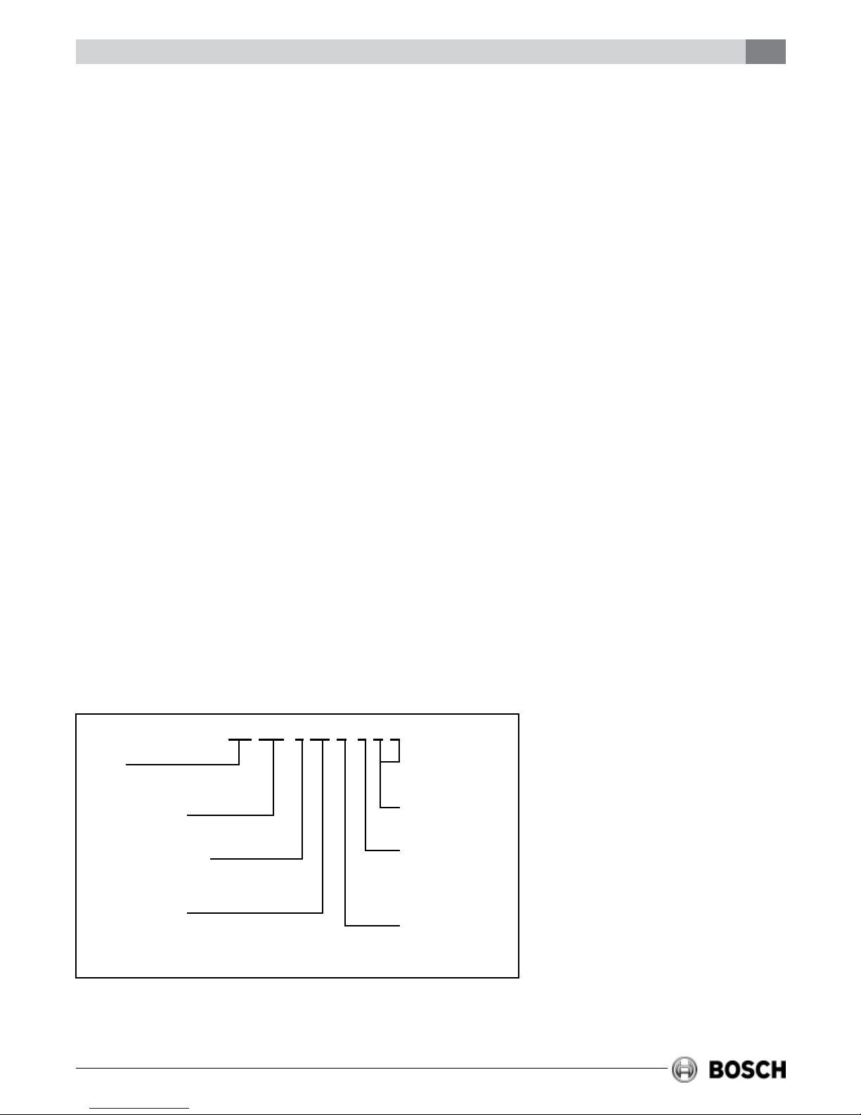
Table of Contents
TW Series / Water to Water
TABLE OF CONTENTS
Model Nomenclature .................................................................................... 3
Initial Inspection .......................................................................................... 4
Installation ................................................................................................... 4
Electrical ...................................................................................................... 5
Piping .......................................................................................................... 5
Cooling Tower / Boiler Applications ............................................................. 6
Well Water Systems ...................................................................................... 7
Earth Coupled Geothermal Systems ............................................................ 7
Typical Load Side Applications ..................................................................... 7
Water to Water Unit Controller ..................................................................... 8
Modes Of Operation .................................................................................... 8
Unit Protection ............................................................................................. 9
User Adjustable Setting Chart .................................................................... 11
Setting Up The Controller .......................................................................... 11
Initial Conguration ................................................................................... 12
System Check-Out...................................................................................... 13
Unit Start-Up .............................................................................................. 13
Heat Recovery Package .............................................................................. 14
Operating Pressures .................................................................................. 16
Chiller Mode .......................................................................................... 16
Boiler Mode ........................................................................................... 16
Wiring Diagrams ......................................................................................... 17
Two Phase - Single Stage ....................................................................... 17
Two Phase - Single Stage Solid State Unit Controller ............................. 18
Unit Check-Out........................................................................................... 19
Trouble Shooting ........................................................................................ 20
3
MODEL NOMENCLATURE
TW 060 - 3 CS C - F X X
MODEL:
TW=WATER TO WATER R-410A
NOMINAL CAPACITY:
THOUSANDS OF BTUH - COOLING
VOLTAGE DESIGNATIONS:
1- 208-230/1/60
CONTROL OPTIONS:
CS: WATER-TO-WATER UNIT NO CONTROLS
US: WATER-TO-WATER UNIT MOUNTED CONTROLLER
Revised 03-11 Subject to change without prior notice
NOT APPLICABLE
WATER CONNECTION
LOCATION
F-FRONT
WATER COIL OPTIONS
C-COPPER
N-CUPRO-NICKEL
6 720 220 047
4
TW Series / Water to Water
Initial Inspection
INITIAL INSPECTION
Be certain to inspect all cartons or crates on each
unit as received at the job site before signing the
freight bill. Verify that all items have been received
and that there is no visible damage; note any
shortages or damage on all copies of the freight
bill. In the event of damage or shortage, remember
that the purchaser is responsible for ling the
necessary claims with the carrier. Concealed
damage not discovered until after removing the
units from the packaging must be reported to the
carrier within 24 hours of receipt.
GENERAL DESCRIPTION
The Water-to-Water series unit is a heat pump that
provides the best combination of performance and
efciency available. Safety devices are built into
each unit to provide the maximum system
protection possible when the unit is properly
installed and maintained.
The Water-to-Water series units are Underwriters
Laboratories (UL) and (cUL) listed for safety. The
Water-to-Water series units are designed to operate
with entering source liquid temperature between
25° F and 110° F. (see specications data sheets
for limits).
For well water applications, the minimum
source EWT is 50˚ F, with sufcient water ow
to prevent freezing. Antifreeze solution is
required for all closed loop applications.
Cooling Tower/Boiler and Earth Coupled (Geo
Thermal) applications should have sufcient
antifreeze solution to protect against extreme
conditions and equipment failure. Frozen water
coils are not covered under warranty.
components. Only trained and qualied personnel
should install, repair, or service the equipment.
Before performing service or maintenance
operations on the system, turn off main power
to the unit. Electrical shock could cause
personal injury or death.
TW Series R-410A refrigerant systems operate
at higher pressures than standard R-22
systems. Do not use R-22 service equipment or
components on R-410A equipment.
When working on equipment, always observe
precautions described in the literature, tags, and
labels attached to the unit. Follow all safety codes.
Wear safety glasses and work gloves. Use a
quenching cloth for brazing, and place a re
extinguisher close to the work area.
LOCATION
The unit should be centrally located with respect to
the distribution system. The unit should be
installed in an indoor area that allows easy removal
of the access panels, and has enough room for
service personnel to perform maintenance or
repair. Provide sufcient room to make uid, and
electrical connections. These units are not
approved for outdoor installation; therefore, they
must be installed inside the conditioned structure.
Do not locate in areas that are subject to freezing.
INSTALLATION
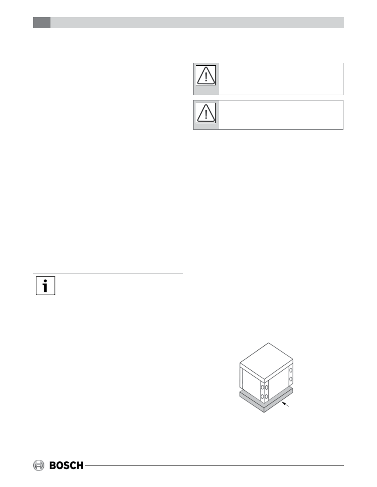
The Water-to-Water series unit should be mounted
level on a vibration absorbing pad slightly larger
than the base to minimize vibration transmission to
the building structure. It is not necessary to anchor
the unit to the oor.
MOVING AND STORAGE
If the equipment is not needed for immediate
installation upon its arrival at the job site, it should
be left in its shipping carton and stored in a clean,
dry area. Units must only be stored or moved in the
normal upright position as indicated by the “UP”
arrows on each carton at all times.
SAFETY CONSIDERATIONS
Installation and servicing of this equipment can be
hazardous due to system pressure and electrical
6 720 220 047
VIBRATION PAD
FULL SIZE
If the unit is installed on a oor over a crawl space,
it should not rest on long, unsupported oor joists.
Vibrations may be created in the joists with the
crawl space acting as an amplier box resulting in
undesirable noise. A drain pan is recommended
Subject to change without prior notice Revised 03-11
Minimal System Volume
TW Series / Water to Water
5
where water released during start-up or
maintenance could cause damage below the unit.
MINIMAL SYSTEM VOLUME
Bosch recommends that the total uid volume in the
system be not less than 6 gallons per nominal ton of
cooling capacity on both the load and source sides.
ELECTRICAL
Always disconnect power to the unit before
servicing to prevent injury or death due to
electrical shock.
All eld wiring must comply with local and national
re, safety and electrical codes. Power to the unit
must be within the operating voltage range
indicated on the unit’s nameplate. On three phase
units, phases must be balanced within 2%.
Properly sized fuse or HACR circuit breakers must
be installed for branch circuit protection. See
equipment rating plate for maximum size. The unit
is supplied with an opening for attaching conduit.
Be certain to connect the ground lead to the
ground lug in the control box. Connect the power
leads as indicated on the unit wiring diagram
(Refer to Figure #6).
PIPING
Supply and return piping must be as large as the
unit connections on the heat pump (larger on long
runs). Never use exible hoses of a smaller inside
diameter than that of the water connections on
the unit. The Water-to-Water series units are
supplied with either a copper or optional cupronickel condenser. Should your well driller express
concern regarding the quality of the well water
available or should any known hazards exist in
your area, we recommend proper testing to assure
the well water quality is suitable for use with
water source equipment. In conditions
anticipating moderate scale formation or in
brackish water a cupro-nickel heat exchanger is
recommended.
Galvanized pipe or ttings are not recommended
for use with these units due to the possible
galvanic corrosion.
Both the supply and discharge water lines will
sweat if subject to low water temperature. These
lines should be insulated to prevent damage from
condensation.
All manual ow valves used in the system must be
ball valves. Globe and gate valves must not be
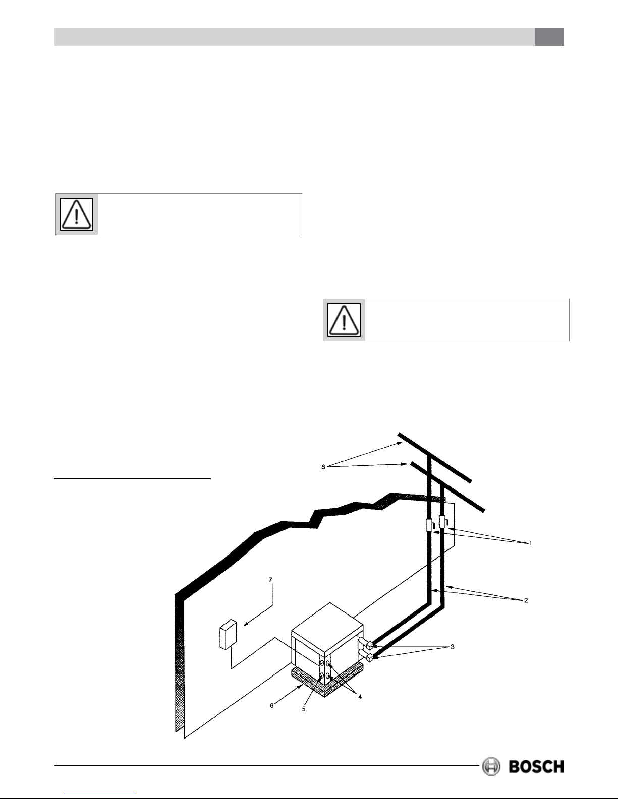
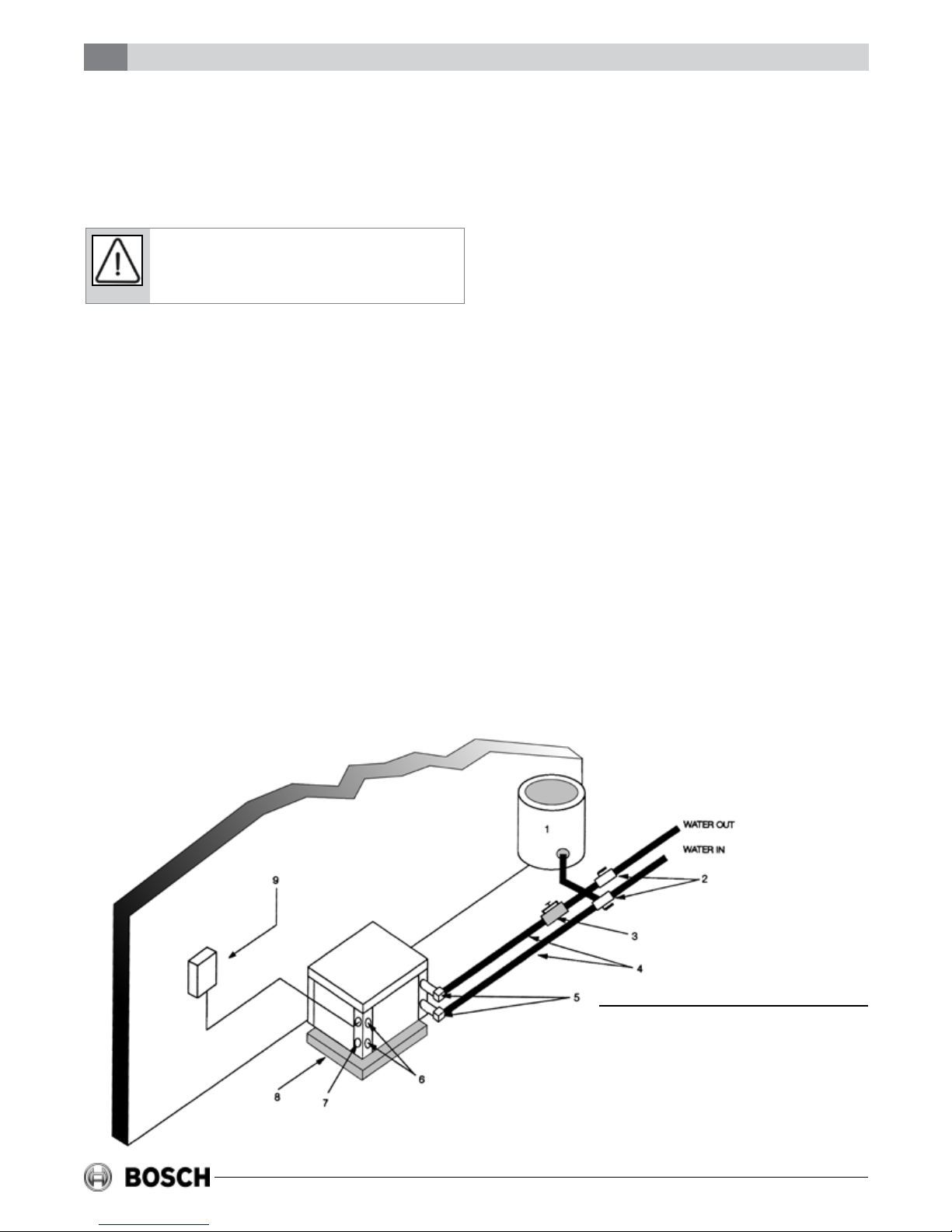
COOLING TOWER/BOILER APPLICATION
(SOURCE SIDE)
1. BALL VALVES
2. HOSE KITS
3. P/T PLUGS
4. LOAD SIDE CONNECTIONS*
5. LOW VOLTAGE CONTROL CONNECTION*
6. VIBRATION PAD
7. LINE VOLTAGE DISCONNECT
8. SUPPLY AND RETURN LINES OF
CENTRAL SYSTEM
* NOTE: Water and electrical connection locations vary depending on model. Connect as required per unit labels.
Figure #1
Revised 03-11 Subject to change without prior notice
6 720 220 047
6
TW Series / Water to Water
Cooling Tower / Boiler Application
used due to high pressure drop and poor throttling
characteristics.
Never exceed the recommended water ow rates.
Serious damage or erosion of the water to
refrigerant heat exchanger could occur.
Improper heat exchanger uid ow due to piping,
valving or improper pump operation is hazardous
to the unit and constitutes abuse which will void
the heat exchanger and compressor warranty.
Always check carefully for water leaks and repair
appropriately. Units are equipped with female pipe
thread ttings. Consult the specication sheets for
sizes. Thread sealant should be used when
connecting water piping connections to the units to
insure against leaks and possible heat exchanger
fouling. Do not overtighten the connections.
Flexible hoses should be used between the unit and
the rigid system to avoid possible vibration. Ball
valves should be installed in the supply and return
lines for unit isolation and unit ow balancing.
COOLING TOWER / BOILER
APPLICATION (Figure #1)
To assure adequate cooling and heating
performance, the cooling tower and boiler uid
loop temperature should be maintained between
50° F to 100° F. In the cooling mode, heat is
rejected from the unit into the condenser water
loop. A cooling tower provides evaporative cooling
to the loop water; thus, maintaining a constant
supply temperature to the unit. When utilizing an
open cooling tower, chemical water treatment is
mandatory to ensure the water is free of corrosive
materials. A secondary heat exchanger (plate frame
between the unit and the open cooling tower) may
also be used. It is imperative that all air is
eliminated from the closed loop side of the heat
exchanger to prevent condenser fouling.
In the heating mode, heat is absorbed from the
condenser water loop to the unit. A boiler can be
utilized to maintain the loop within the proper
temperature range. In milder climates a “ooded
tower” concept is often used. This concept involves
adding make-up water to the cooling tower sump to
maintain the desired loop temperature. No unit
should be connected to the supply or return piping
until the water system has been completely cleaned
and ushed to remove any dirt, piping chips or
other foreign material. Supply and return hoses
should be connected together during this process
to ensure the entire system is properly ushed.
After the cleaning and ushing has taken place, the
unit may be connected to the water loop and should
have all valves wide open.
Pressure/temperature ports are recommended in
both the supply and return lines for system ow
balancing. Water ow can be accurately set by
measuring the refrigerant-to-water heat exchangers
* NOTE: Water and electrical connection locations vary
depending on model. Connect as required per unit labels.
6 720 220 047
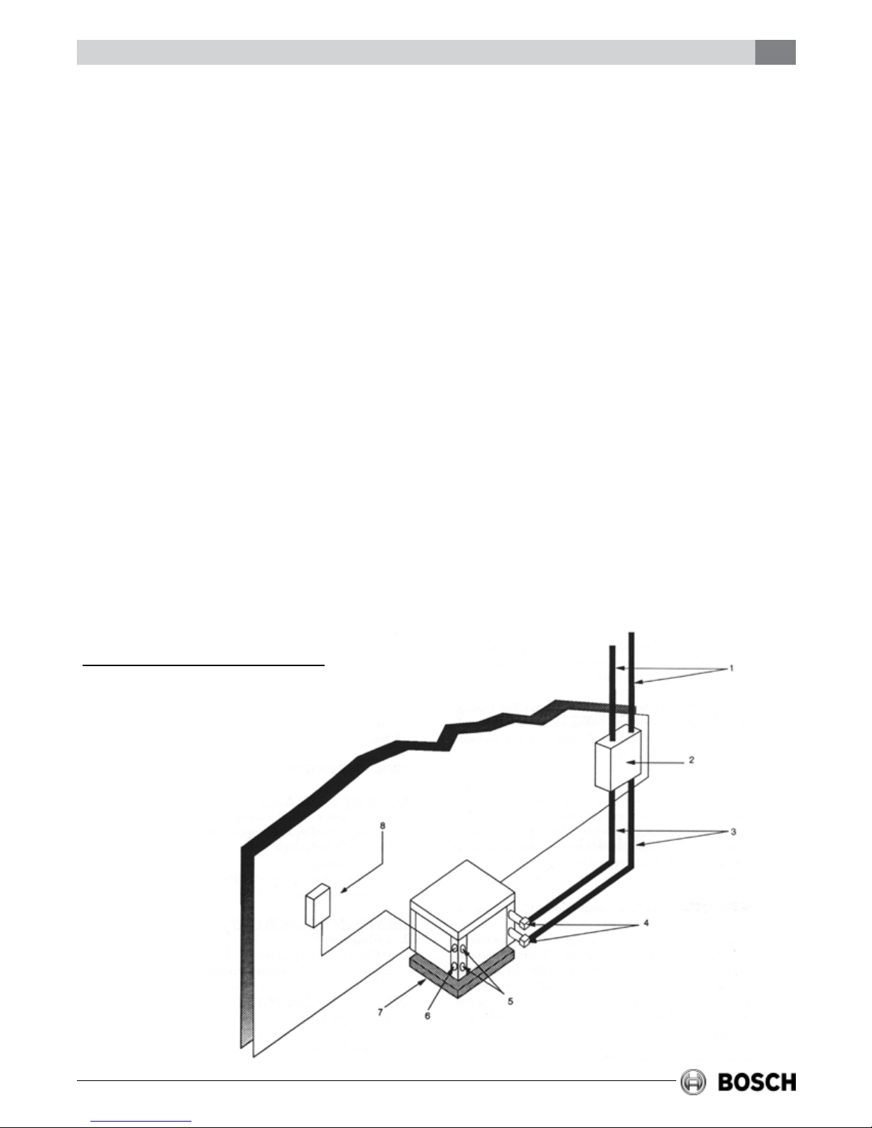
WELL WATER APPLICATION (SOURCE SIDE)
1. PRESSURE TANK
2. BALL VALVES
3. SOLENOID VALVE (SLOW CLOSING)
4. HOSE KIT
5. P/T KIT
Figure #2
Subject to change without prior notice Revised 03-11
6. LOAD SIDE CONNECTIONS*
7. LOW VOLTAGE CONTROL CONNECTION*
8. VIBRATION PAD
9. LINE VOLTAGE DISCONNECT
Well Water Systems
TW Series / Water to Water
7
water side pressure drop. See specication sheets
for water ow and pressure drop information.
WELL WATER SYSTEMS (Figure #2)
Water quantity should be plentiful, between 1.5
and 3.0 gpm per ton of cooling, and of good quality.
To avoid the possibility of freezing in the heating
mode, the well water should be above 50˚F.
Water pressure must always be maintained in the
heat exchanger by placing a water control valve on
the outlet of the water-to-water unit. A bladder type
expansion tank may be used to maintain pressure
on the system. All solenoid valves should be slow
closing to avoid water hammer.
The discharge water from the water-to-water unit is
not contaminated in any manner and can be
disposed of in various ways depending on the local
codes (i.e. discharge well, dry well, storm sewer,
drain eld, stream, pond, etc.) Pilot operated or
slow closing valves are recommended to reduce
water hammering.
EARTH COUPLED GEOTHERMAL
SYSTEMS (Figure #3)
Closed loop and pond applications require
specialized design knowledge. No attempt at these
installations should be made unless the dealer has
received specialized training.
Utilizing the Ground Loop Pumping Package
(GLP), makes the installation easy. Anti-freeze
solutions are utilized when entering loop
temperatures drop below 50˚F or where piping
will be routed through areas subject to freezing. A
ow rate between 2.5 to 3.0 gpm per nominal ton
of cooling is recommended for this application.
See GLP Pump Curve for sizing information.
TYPICAL LOAD SIDE APPLICATIONS
There are many load side applications for which
the water-to-water heat pump/ liquid chiller is
ideally suited.
SOME TYPICAL USES ARE AS
FOLLOWS
Hydronic baseboard heating, hydronic in-slab oor
heating, forced air fan coil heating or cooling, ice
and snow melting, heating potable water, (when
allowed by code) heating swimming pool and spa*,
process uid heating or cooling.
When specifying load side uid volume it is
important to consider the heat pump output
capacities and ow rates. Insufcient load side
uid volume may cause unstable heat pump
operation (short cycling). Pressure/temperature
ports should be used to set ow rates.
EARTH COUPLED APPLICATION (SOURCE SIDE)
1. POLYBUTYLENE OR POLYETHELENE WITH
INSULATION
2. GROUND LOOP PUMPING PACKAGE (GLP)
3. GROUND LOOP CONNECTION KIT
4. P/T PLUGS
5. LOAD SIDE CONNECTIONS*
6. LOW VOLTAGE CONTROL CONNECTION*
7. VIBRATION PAD
8. LINE VOLTAGE DISCONNECT
Figure #3
* NOTE: Water and electrical connection locations vary depending
on model. Connect as required per unit labels.
Revised 03-11 Subject to change without prior notice
6 720 220 047

8
TW Series / Water to Water
Water to Water Unit Controller
*A water-to-water series Heat Pump/Liquid Chiller
can be utilized for direct pool/spa heating without a
secondary heat exchanger. In this application
cupro-nickel heat exchangers must be used.
Automatic chemical feeders must never be installed
up stream of the unit. An external bypass should be
installed to avoid over-owing the heat exchanger
to prevent coil erosion. The pool pH levels and
chemical balances must be maintained to avoid
possible heat exchanger damage.
WATER TO WATER UNIT CONTROLLER
(OPTIONAL)
Bosch’s water to water heat pump controller offers a
low cost, simple solution to the control of a water to
water heat pump unit. The control is congurable to
provide cooling only, heating only or auto change over
control strategies based on the application of the unit
in a given system.
Features:
• Selectable mode of operation. Cooling, Heating or
Auto Changeover.
• Adjustable temperature differential for heating
and cooling set point.
• Adjustable auto changeover set point with adjust-
able dead band setting.
• Intelligent auto reset of a fault condition avoids
nuisance hard lockouts.
• LED display of control temperature and set
points.
• ˚F or ˚C Display.
• 50\60 Hertz operation.
• Brown out low voltage protection
All of the unit’s safeties are tied back into the
controller for system protection.
UNIT SENSORS
The unit controller is provided with two sensors:
Water Sensor: This sensor will control unit
operation in the cooling or heating mode based on
the water temperature on the load side. It may be
eld mounted for example on the return water line
or in a water tank when provided with a eld
supplied immersion well. The location will depend
on the specic requirements of the job.
Changeover Sensor: This sensor will put the unit in
either the heating or cooling mode depending on
the set point. It may be mounted in a location that
would be indicative if the unit should be in either
the heating or cooling mode, for example outdoors.
The sensor may be located up to 1000 feet from the
unit (additional eld supplied wiring required).
MODES OF OPERATION
The controller will memorize the last mode used
before power is removed and will run in that mode
after it is turned on. In all modes the control will
display temperature degree differential setting for ve
seconds once it is powered and this setting may be
adjusted during this time. Thereafter the display will
switch to the monitored water temperature. When
switching from one mode to another the set point (the
decimal point is used to distinguish it from water
temperature) for the new mode is displayed for 5
seconds and then monitored water temperature.
During this time the set point may be adjusted.
• Pump operation congurable for continuous or
cycling operation with the compressor.
• Compressor lead-lag operation on units with dual
compressors.
• Malfunction output and service LED can be set to
steady or pulsing to indicate fault condition.
• Color LED’s indication of mode of operation.
• Set point retention in non volatile memory in the
event of a power failure.
• Five minute delay on break or power interruption
for compressor short cycling protection.
6 720 220 047
OFF MODE
In the OFF mode all outputs are disabled and mode
indication LED’s will be off.
The control will rst display temperature
differential setting with the ability for the user to
adjust it and then will display “OFF” and nally
water temperature.
HEATING MODE
When the unit is operated in the heating mode and
the controlled water temperature is below the set
point minus the differential setting, terminal Y1 will
close and the unit will operate (rst stage
Subject to change without prior notice Revised 03-11
 Loading...