

Bosch TSTBM-RRS--TW-A Installation Manual
Thermostat
Installation Manual
Series
TSTBM-RRS--TW-A REMOTE TEMPERATURE SENSOR
(REQUIRES TSTBM3H2CPH6W-A)
TSTBM-RRS--TW-A
6 720 220 377 Revised 02-13

Table Of Contents
2 TSTBM-RRS--TW-A
TABLE OF CONTENTS
Thermostat Quick Reference ................................................................................. 3
Wireless Range ................................................................................................... 3
Mounting Locations ............................................................................................... 3
Remote Sensor Locations ..................................................................................... 3
Wireless Range ................................................................................................... 4
Mounting Options .................................................................................................. 4
Installing Batteries ................................................................................................ 5
Connecting to the Master Thermostat ................................................................... 6
Easy Communication Link Set up ....................................................................... 6
Technician Setup Menu ......................................................................................... 7
Sensor Only Mode ................................................................................................. 9
Adjustable Remote Mode....................................................................................... 9
Specications ...................................................................................................... 11
Contact Your Local Bosch Dealer. ........................................................................ 11
Limited Warranty ................................................................................................. 12
Warranty .............................................................................................................. 13
6 720 220 377
Subject to change without prior notice Revised 02-13
Mounting Locations
the temporary setpoint hold.
must
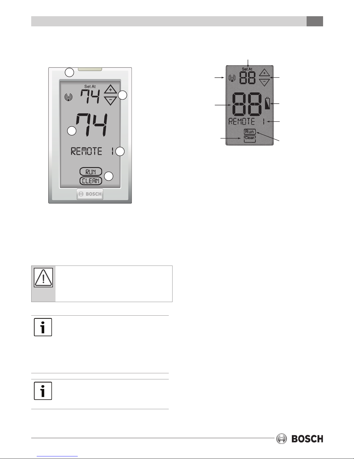
THERMOSTAT QUICK REFERENCE
Getting to know your indoor remote
sensor TSTBM-RRS--TW-A
2
3
1
4
5
Wireless Icon
Temperature
Indicates the current
ambient temperature.
Clean Key
Pressing the CLEAN key
will allow 30 seconds to
clean the display. The keys
will be inoperable during
this time. NOTE: The Show
Set mode must be set to
YES in tech setup menu
before the CLEAN key will
be displayed.
Setpoint Temperature
Displays the user selectable
setpoint temperature.
3TSTBM-RRS--TW-A
Setpoint Adjustment Keys
NOTE: The SHOW SET must
be set to YES
menu before the setpoint
keys will be shown in the
display.
Low Battery Indicator
Replace batteries when
this indicator is shown.
Remote Label
Each indoor remote
sensor can be labeled.
The label options can be
found during tech setup.
Run Key
RUN only shows if the
remote sensor setpoint
has been changed.
Pressing RUN will cancel
Note: The SHOW SET
be set to YES in tech setup
menu before the RUN key
will be shown in the display.
in tech setup
1. LCD Display
2. Glow in the Dark Light Button*
3. Temperature Setpoint Buttons**
4. Remote Name
5. Run and Clean Keys**
Mercury Notice: All Bosch thermostats are
mercury free. However, if the product you are
replacing contains mercury, dispose of it
properly. Your local waste management
authority can give you instructions on recycling.
*NOTE ABOUT THE LIGHT BUTTON:
This button is used to light up the display. DO
NOT hold the light button down for longer
than 3 seconds or you will enter the
technician setup screens. If you inadvertently
enter the tech setup press and release the
light button a second time to exit the tech
screens.
**NOTE ABOUT SETPOINT, RUN AND
CLEAN KEYS: These keys will only be
shown if they have been turned on in
Technician Setup menu.
WIRELESS RANGE
Range between the TSTBM-RRS--TW-A and the
TSTBM3H2CPH6W-A master thermostat is up to 100
feet with no obstructions and up to 50 feet in
standard residential metal, brick, and concrete
construction.
MOUNTING LOCATIONS
REMOTE SENSOR LOCATIONS
The remote sensor should be mounted or placed
approximately 4 to 5 feet above the oor. Select an area
with average temperature and good air circulation.
Do not install remote room sensors in locations that are:
• On an exteriorwall
• In direct sunlight
• Where there may be concealed chimneys or pipes
behind the wall
• Close to a window or door leading outside
• Close to objects radiating heat such as replaces,
lighting, space radiators, or any other appliance
• In areas that do not require conditioning
• In dead spots or where drafts can occur (behind
doors or in corners)
Revised 02-13 Subject to change without prior notice
• Close to hot or cold air ducts
6 720 220 377
4 TSTBM-RRS--TW-A
Mounting Options
WIRELESS RANGE
Range between the TSTBM-RRS--TW-A and the
TSTBM3H2CPH6W-A master thermostat is up to 100
feet with no obstructions and up to 50 feet in
standard residential metal, brick, and concrete
construction.
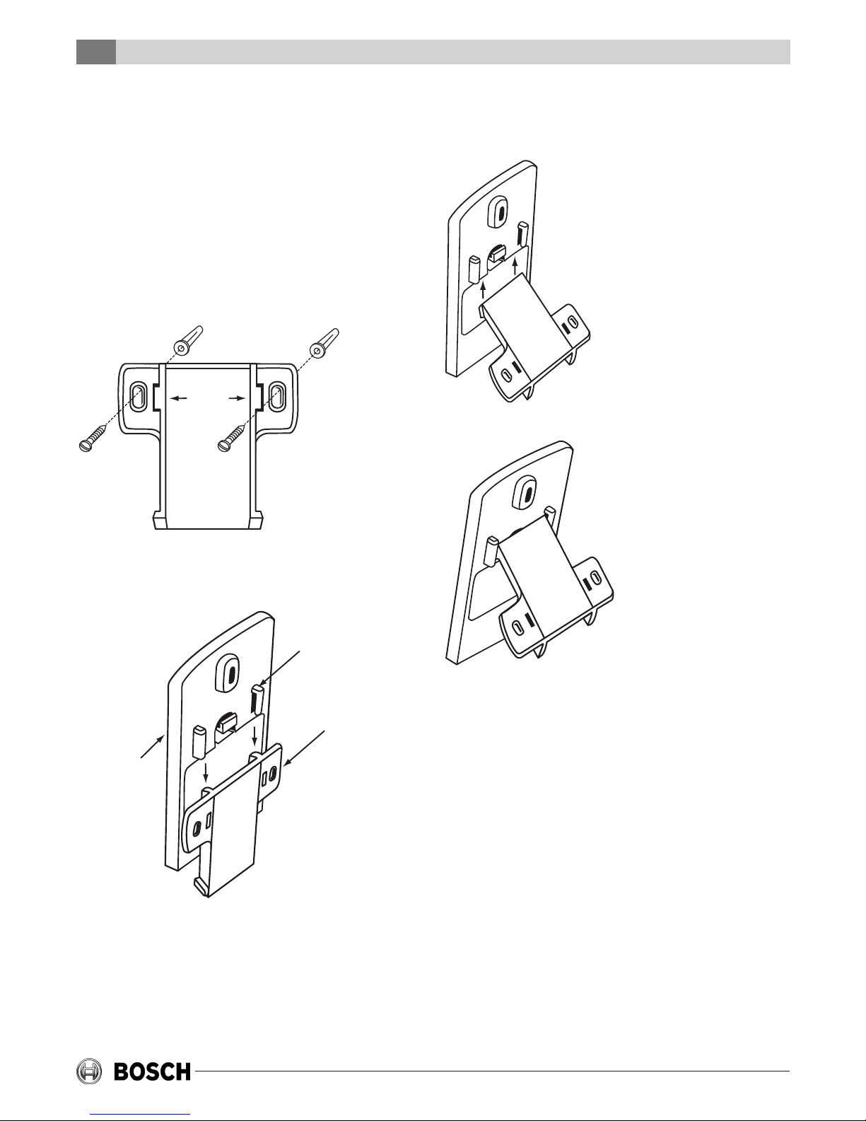
MOUNTING OPTIONS
Wall Mount - Removable
1. Mount T-bracket on the Wwall.
Wall
mount
slots
Desk or Counter Option
1. Slide the T-bracket up into the slot holders.
2. T-bracket will stop on the top of the slot holders.
T-bracket
2. Slide the Remote Sensor over the mounted
T-bracket.
Wall mount
slot holders.
Back View
of Subbase
of Remote
Sensor
T-bracket
mounted on
the wall
6 720 220 377
Subject to change without prior notice Revised 02-13
Installing Batteries
5TSTBM-RRS--TW-A
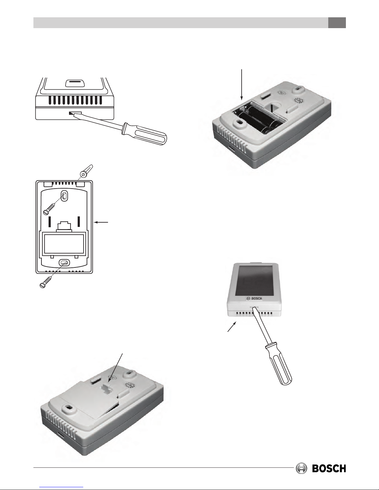
Wall Mount - Permanent
1. Remove the TSTBM-RRS--TW-A from the
subbase.
2. Mount subbase to the wall.
Inside View
of Subbase
of Remote
Sensor
2. Once you have removed the door from the back
of the remote, insert 2 AA Alkaline batteries and
replace the battery door.
Inserting Batteries for Permanent
Wall Mount
1. Remove the TSTBM-RRS--TW-A from the
subbase. The TSTBM-RRS--TW-A is held on the
subbase by a plastic tab on the bottom of the
remote sensor. Push in with a small at head
screwdriver to remove the TSTBM-RRS--TW-A
from the subbase.
INSTALLING BATTERIES
Installing Batteries for Temporary Wall
Mount or Table Placement
1. Use the nger tab on the back of the remote to
remove the battery door.
Revised 02-13 Subject to change without prior notice
Bottom of
Remote Sensor
6 720 220 377
 Loading...