

Bosch TSTBM3H2CPH6W-A, tTSTBM3H2CPH6W-A Installation Manual
Thermostat
Installation Manual
Series
TTSTBM3H2CPH6W-A THERMOSTAT AND
WIRELESS COMMUNICATING BASE MODULE
TSTBM3H2CPH6W-A
6 720 220 376 Revised 02-13
Table of Contents
2 TSTBM3H2CPH6W-A
TABLE OF CONTENTS
Thermostat Applications Guide ............................................................................. 3
Power Type ............................................................................................................ 3
Thermostat Quick Reference ................................................................................. 3
Installation Tips ..................................................................................................... 4
Removing the Private Label Badge ........................................................................ 4
Wall locations ........................................................................................................ 4
Base Module—Basement Installation ..................................................................... 5
Base Module—Attic Installation ............................................................................. 5
Wiring .................................................................................................................... 5
Base Module Subbase Installation ........................................................................ 5
Thermostat Installation and wiring ........................................................................ 6
Battery Installation ................................................................................................ 6
Mount Thermostat and Base Module ..................................................................... 7
Wiring Schematicss ............................................................................................... 8
Terminal Designations on Base Module ............................................................... 12
Terminal Designations on TSTBM3H2CPH6W-A Master Thermostat ................... 12
Powering the TSTBM3H2CPH6W-A Master Thermostat ...................................... 12
Establishing Communication between TSTBM3H2CPH6W-A
Master Thermostat and the Base Module ............................................................ 13
Using Multiple TSTBM3H2CPH6W-A wireless thermostats ................................. 13
Technician Setup Menu ....................................................................................... 14
Understanding Swing And Staging ..................................................................... 22
HUM Terminal ...................................................................................................... 22
DHM Terminal ...................................................................................................... 22
Humidication / Dehumidication Recommendation for Bosch Heat Pump ...... 23
Setting Target Humidity Setpoint ........................................................................ 23
Ambient Humidity Display ................................................................................... 23
Recommended Cooling Settings: ........................................................................ 24
Set Time .............................................................................................................. 24
Programming ....................................................................................................... 24
Specications ..................................................................................................... 27
Troubleshooting .................................................................................................. 27
Contact your local Bosch Dealer. ......................................................................... 28
Limited Warranty ................................................................................................. 29
Warning: If you are setting up this thermostat for an AC unit with electric
heat, or gas furnace, it is imperative that the the “FAN OPERATION”
menu feature is set to ELE or GAS, which ever applies. The default
setting is GAS; if electric heat strips are installed and the default value
of GAS is used, it is possible that the electric heat strips can become
energized without the blower motor on when there is a call for heat.
Reference the Tech Menu Setup section on how to change this feature.
6 720 220 376
Subject to change without prior notice Revised 02-13
Thermostat Quick Reference
3TSTBM3H2CPH6W-A
The TSTBM3H2CPH6W-A offers the
following:
• 3 stages of heating
• 2 stages of cooling
• Temperature averaging with remote sensors
• Wireless control
• 5+1+1 & 7 Day Programmable
THERMOSTAT APPLICATIONS GUIDE
Description
Gas or Oil Heat Yes
Electric Furnace Yes
Heat Pump (No Aux. or Emergency Heat) Yes
Heat Pump (with Aux. or Emergency Heat) Yes
Multi-stage Systems Yes
Heat Only Systems Yes
Cool Only Systems Yes
Dual Fuel Systems Yes
Millivolt No
Humidity Yes
Auto Change Over Yes
POWER TYPE
• Battery Power*
• Hardwire (Common Wire)
• Hardwire (Common Wire) with Battery Backup
* If using remote sensors the thermostat must be
hardwired.
A trained, experienced technician must
install this product. Carefully read these
instructions. You could damage this product
or cause a hazardous condition if you fail to
follow these instructions.
This thermostat is shipped from the factory to
operate a conventional heating and cooling
system. This thermostat will also operate a
heat pump system. See the “heat pump”
con guration step in the Tech Menu setup of
this manual to congure the thermostat for
heat pump applications.
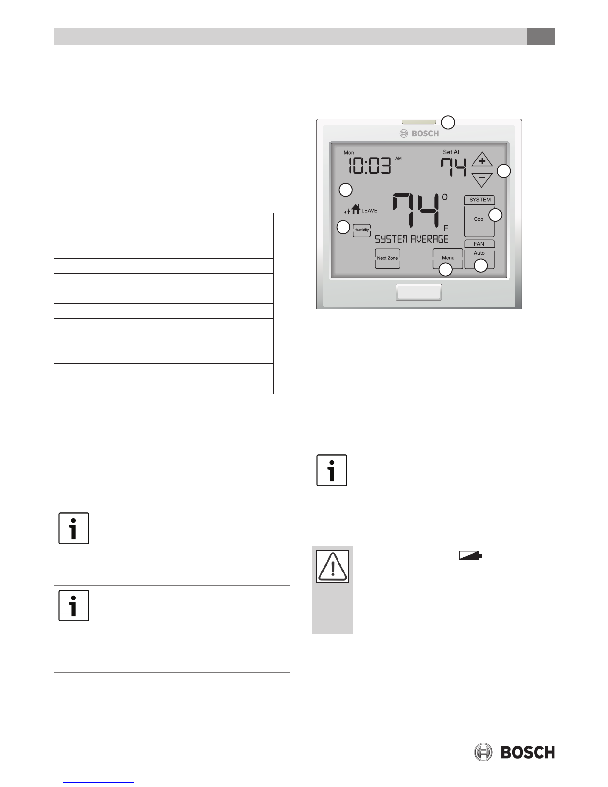
THERMOSTAT QUICK REFERENCE
Getting to know your thermostat
2
5
1
4
7
6
1. LCD Display
2. Glow in the Dark Light Button*
3. Fan Button
4. System Button
5. Temperature Setpoint Buttons
6. Menu Button
7. Humidity Button
NOTE ABOUT THE LIGHT BUTTON:
This button is used to light up the display, but
it is also used to set up communication with
the base module. DO NOT hold the light
button down for more then 10 seconds,
unless you are performing the initial
communication setup steps.
The low battery indicator
when the AA battery power is low. If the user
fails to replace the battery within 21 days, the
thermostat display will only show the low
battery indicator as a nal warning before the
thermostat becomes inoperable. The batteries
are located on the back of the thermostat.
3
is displayed
Revised 02-13 Subject to change without prior notice
6 720 220 376
1
2
7
4
THERMOSTAT QUICK REFERENCE
4 TSTBM3H2CPH6W-A
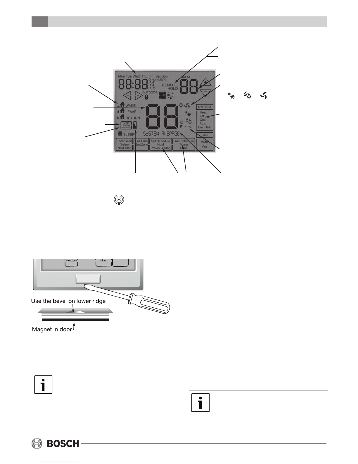
Installation Tips
Days of the week and time. Flashes ambient
humidity level. May also flash outside temperature
when used with TSTBM-OTS--TW-A. OUTDOOR will show.
Programmable Time
Period Icons:
This thermostat has
4 programmable
time periods per day.
Temperature:
Indicates the current
system temperature.
Humidity:
Shows the humidity target
setpoint settings and keys.
Clean Display:
Pressing CLEAN DISPLAY
will allow 30 seconds to clean
the display. The keys will be
inoperable during this time.
CLEAN will appear if your
contractor has programmed a
filter change reminder. Press
CLEAN when filter has been
replaced to reset the filter
change reminder timer.
Low Battery Indicator:
Replace batteries when
this indicator is shown.
Wireless Icon
Program Menu Options:
Shows different options
during programming.
REMOTE indicates a remote
has control of the system.
HOLD is displayed when thermostat
program is permanently overridden.
Displays the user selectable
setpoint temperature.
System operation indicators:
COOL HEAT FAN
The COOL, HEAT or FAN icon will display
when the COOL, HEAT or FAN is on.
NOTE: The compressor delay feature is
active if these icons are flashing. The
compressor will not turn on until the
5 minute delay has elapsed.
Additional Stages of Heating or Cooling;
+1 represents 1 additional stage of
cooling or heating (2 total); +2 means
2 additional stages of heating (3 total)
System Information:
Shows which zone or zones are
controlling your system. Shown only
when one or more indoor sensors
TSTBM-RRS--TW-A are connected.
INSTALLATION TIPS
REMOVING THE PRIVATE LABEL BADGE
Gently slide a scredriver into the bottom edge of the
badge. Gently trun the screwdriver counter
clockwise. The badge should pry off easily. Do not
use force.
All Bosch thermostats use the same
universal magnetic badge. Contact your local
Bosch distributor to learn more about our
free private label program.
WALL LOCATIONS
The thermostat should be installed approximately 4
to 5 feet above the oor. Select an area with average
temperature and good air circulation.
Do not install thermostats in locations that are:
• On an exterior wall
• In direct sunlight
• Where there may be concealed chimneys or pipes
behind the wall
• Close to a window or door leading outside
• Close to objects radiating heat such as replaces,
lighting, space radiators, or any other appliance
• In areas that do not require conditioning
• In dead spots or where drafts can occur (behind
doors or in corners)
• Close to hot or cold air ducts
Pick an installation location that is easy for
the user to access. The temperature of the
location should be representative of the
building.
6 720 220 376
Subject to change without prior notice Revised 02-13
Base Module—Basement Installation
Installation
5TSTBM3H2CPH6W-A
BASE MODULE—BASEMENT
INSTALLATION
Wireless Range
Range between the TSTBM3H2CPH6W-A and the
base module is up to 100 feet with no obstructions
and up to 50 feet in standard residential metal,
brick, and concrete construction. To extend the
range try placing the base unit higher if in a
basement or further away from large metal objects.
Do not install the base module in locations:
• Where temperatures could exceed 150°F
• That could be exposed to rain or snow
• That could be exposed to freezing conditions
• That are behind a chimney
• Where high moisture is possible
The base module is NOT water or
weatherproof and should only be installed in a
conditioned space.
WIRING
1. If you are replacing a thermostat, make note of
the terminal connections on the thermostat
that is being replaced. In some cases the wiring
connections will not be color coded. For
example, the green wire may not be connected
to the G terminal.
2. Loosen the terminal block screws. Insert wires
then retighten terminal block screws.
All components of the control system and the
thermostat installation must conform to
Class II circuits per the NEC Code.
Wire specications
Use shielded or non-shielded 18 - 22 gauge
thermostat wire.
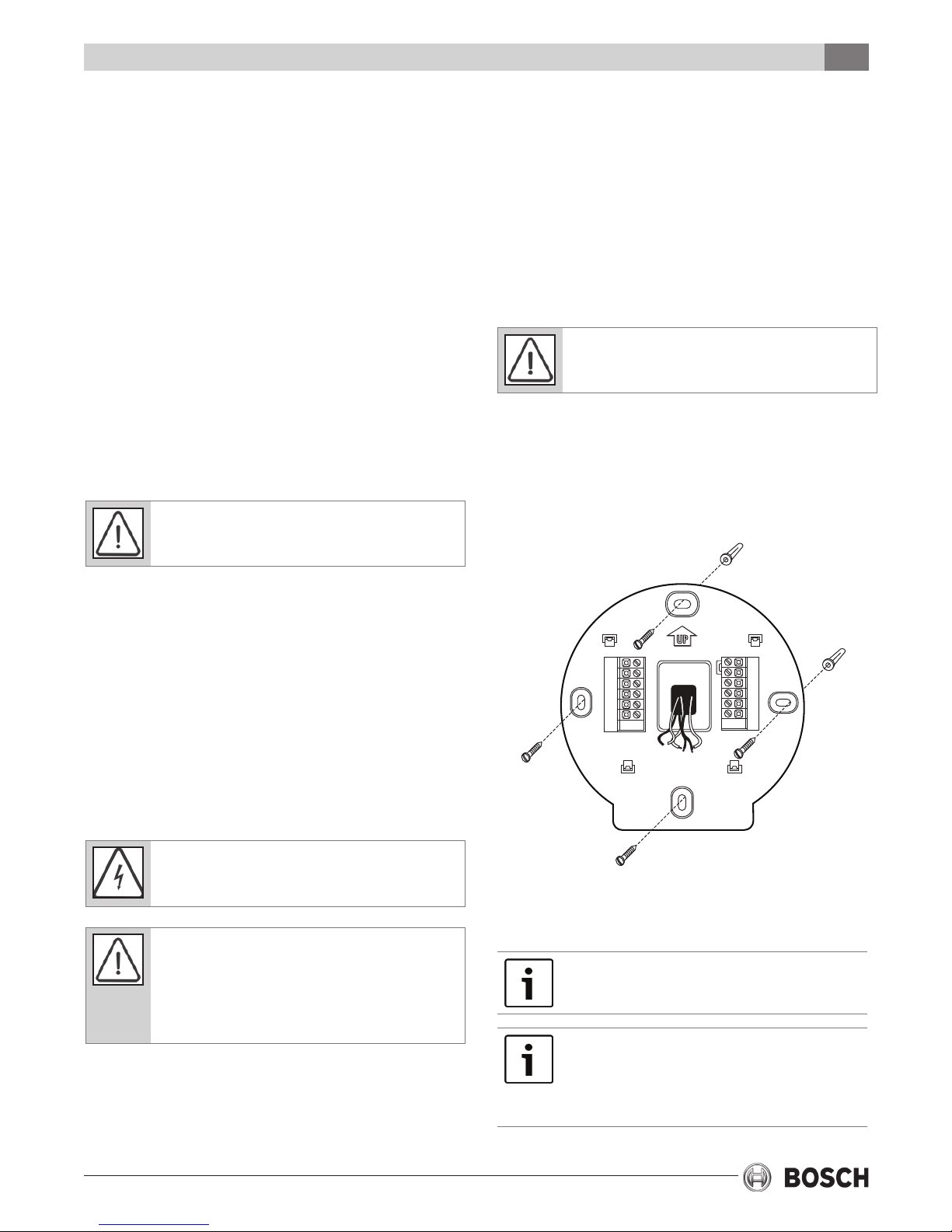
BASE MODULE SUBBASE
INSTALLATION AND WIRING
Vertical mount
BASE MODULE—ATTIC INSTALLATION
Attic installation of the base module should be
avoided. Instead, locate a closet near the air
conditioning unit, then mount the base module high
on the wall inside the closet or on the ceiling of the
closet. This location will insure the base module is
below the 150ºF maximum ambient temperature
specication.
For vertical mount put one screw top and one screw
bottom. For horizontal mount put one screw left
and one screw right.
Failure to disconnect the power before
beginning to install this product can cause
electrical shock or equipment damage.
Mercury Notice: All Bosch thermostats are
mercury free. However, if the product you are
replacing contains mercury, dispose of it
properly. Your local waste management
authority can give you instructions on recycling
and proper disposal.
UP
Rh
Rc
G
Y1
Y2
D
Horizontal mount
Horizontal mount
C
O
B
W1/E
W2
H
Vertical mount
For vertical mount put one screw top and one
screw bottom. For horizontal mount put one screw
left and one screw right.
Wire the base module’s subbase the same
way you would wire a hardwired thermostat
subbase.
To establish communication from the base
module to master thermostat, refer to the
directions in the TSTBM3H2CPH6W-A
Thermostat-Base Module Communication
setup procedure below in this manual.
Revised 02-13 Subject to change without prior notice
6 720 220 376
6 TSTBM3H2CPH6W-A
Thermostat Installation and Wiring
The base module must be hardwired
(C and R terminals connected to 24V power).
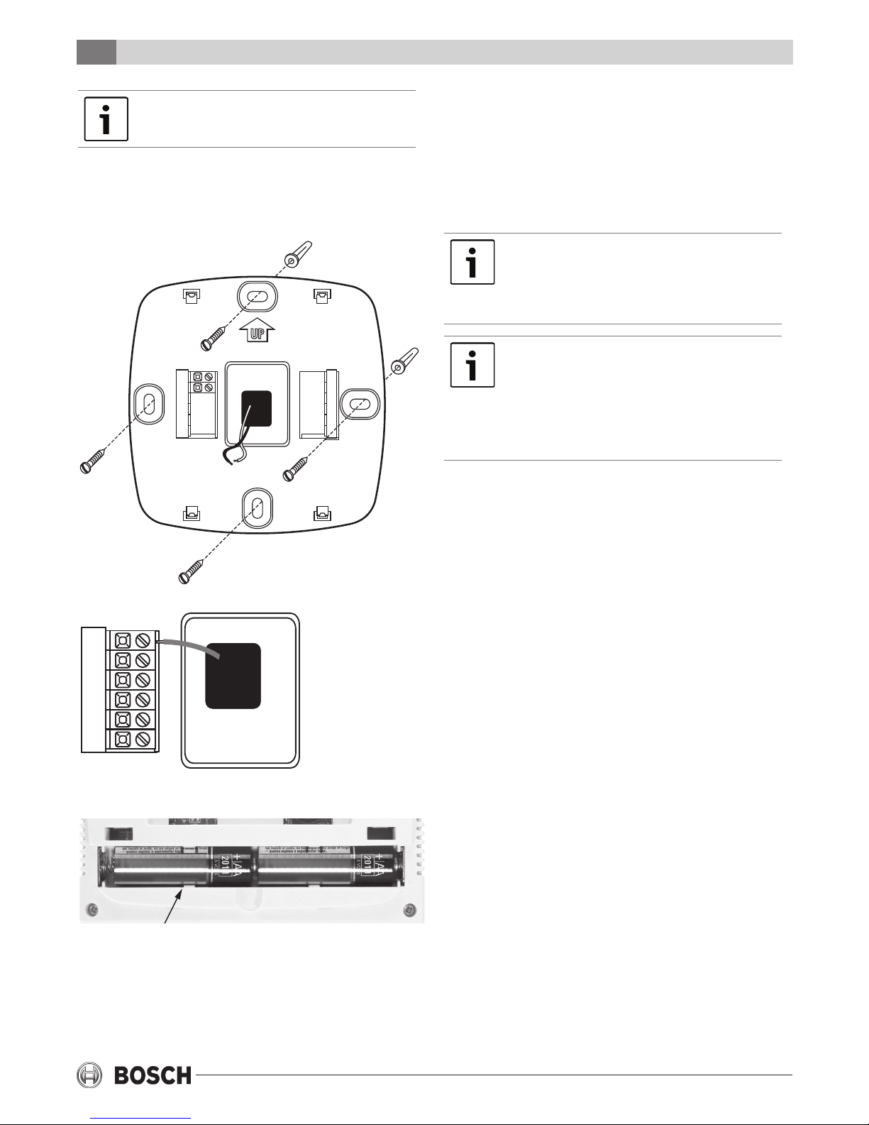
THERMOSTAT INSTALLATION AND
WIRING
Vertical mount
UP
C
R
Horizontal
mount
Horizontal
mount
BATTERY INSTALLATION
Battery installation is optional if there are no
remotes connected to the Master Thermostat (C
terminal connected). If you connect an outdoor
remote and/or indoor remote sensors it is required
the thermostat be hardwired.
To ensure a solid t between the thermostat
and the subbase, mount the subbase on a
at wall with the drywall anchors ush to the
wall. Using the screws and drywall anchors
that were provided with the thermostat.
The TSTBM3H2CPH6W-A can be battery
powered only if used as a stand-alone
thermostat solution. The TSTBM3H2CPH6W-A
must be hardwired (C and R terminals
connected to 24V power) if remote sensors
(TSTBM-RRS--TW-A or TSTBM-OTS--TW-A)
are used.
Vertical mount
C
R
On the back of the thermostat insert 2 AA
Alkaline batteries (included).
6 720 220 376
Subject to change without prior notice Revised 02-13
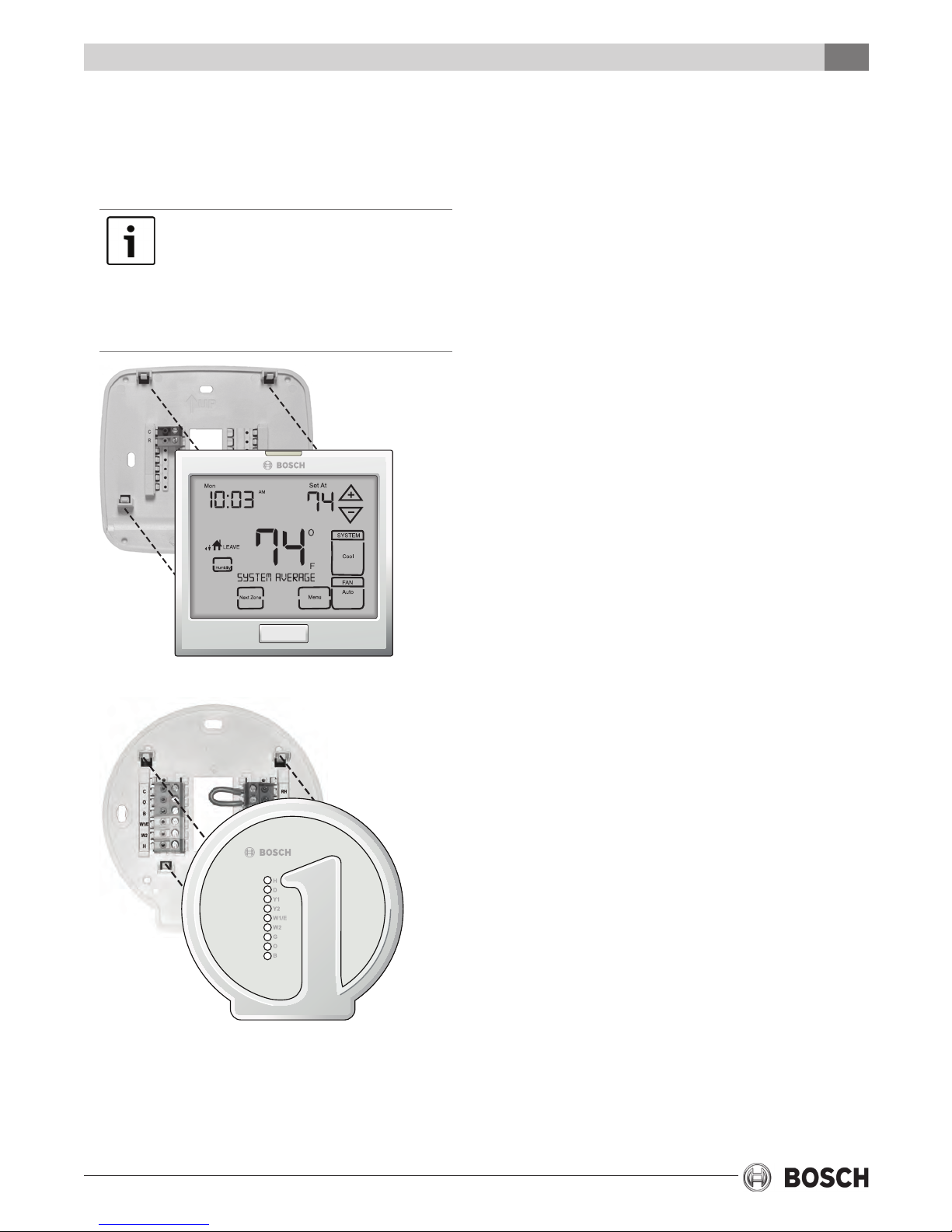
MOUNT THERMOSTAT AND BASE
MODULE
Align the 4 tabs on the subbase with corresponding
slots on the back of the thermostat or base module.
Then push gently until the thermostat or base module.
To insure a solid t between the
thermostat and the subbase:
1. Mount subbase to a at wall
2. Use screws provided
3. Drywall anchors should be ush with the wall
4. Wires should be pushed into the wall
7TSTBM3H2CPH6W-AMount Thermostat And Base Module
Revised 02-13 Subject to change without prior notice
6 720 220 376
8 TSTBM3H2CPH6W-A
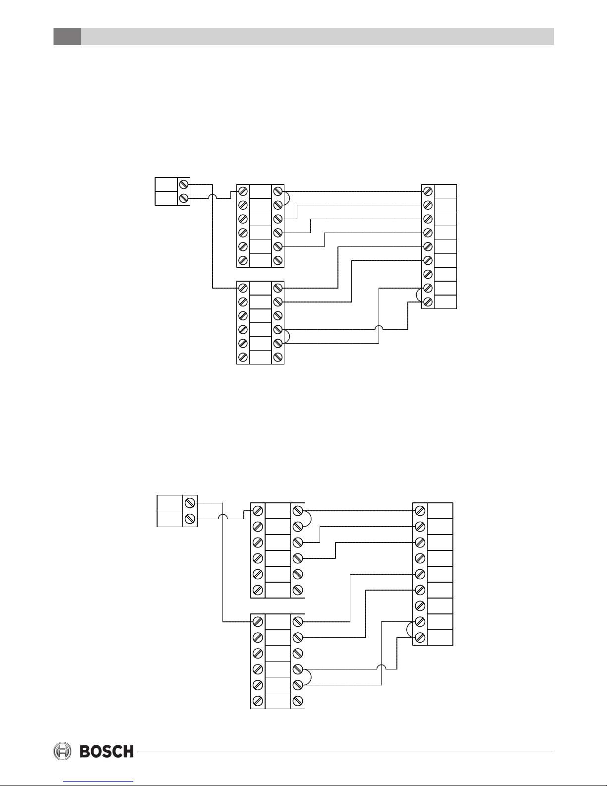
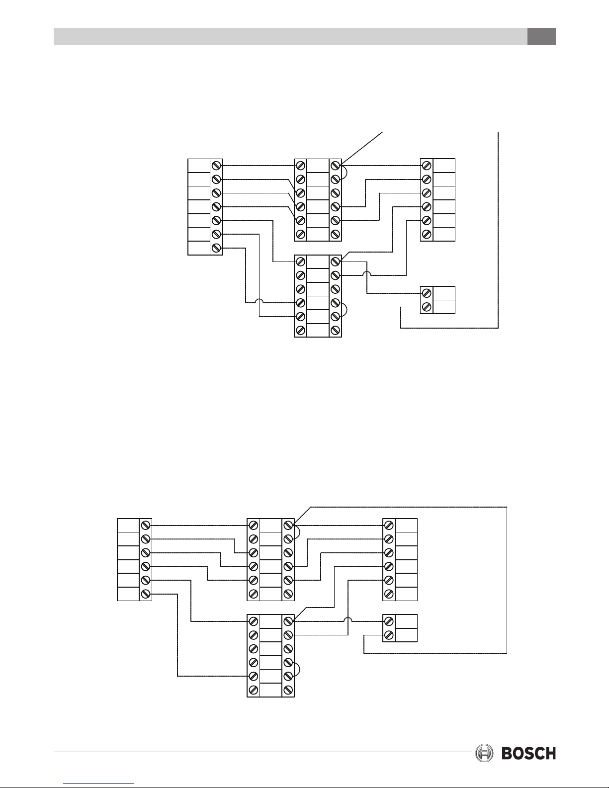
TYPICAL WIRING SCHEMATICS
WIRELESS WITH BASE MODULE TSTBM3H2CPH6W-A
3H/2C HEAT PUMP
TSTBM3H2CPH6W-A
THERMOSTAT
C
R
BASE MODULE
RH
RC
G
Y1
Y2
D
C
O
B
W1/E
W2
H
Wiring Schematics
PACKAGED
HEAT PUMP
R
G
Y1
Y2
C
O
B
W1
W2/E
TSTBM3H2CPH6W-A
THERMOSTAT
C
R
2H/1C HEAT PUMP
BASE MODULE
RH
RC
G
Y1
Y2
D
C
O
B
W1/E
W2
H
PACKAGED
HEAT PUMP
R
G
Y1
Y2
C
O
B
W1
W2/E
6 720 220 376
Subject to change without prior notice Revised 02-13
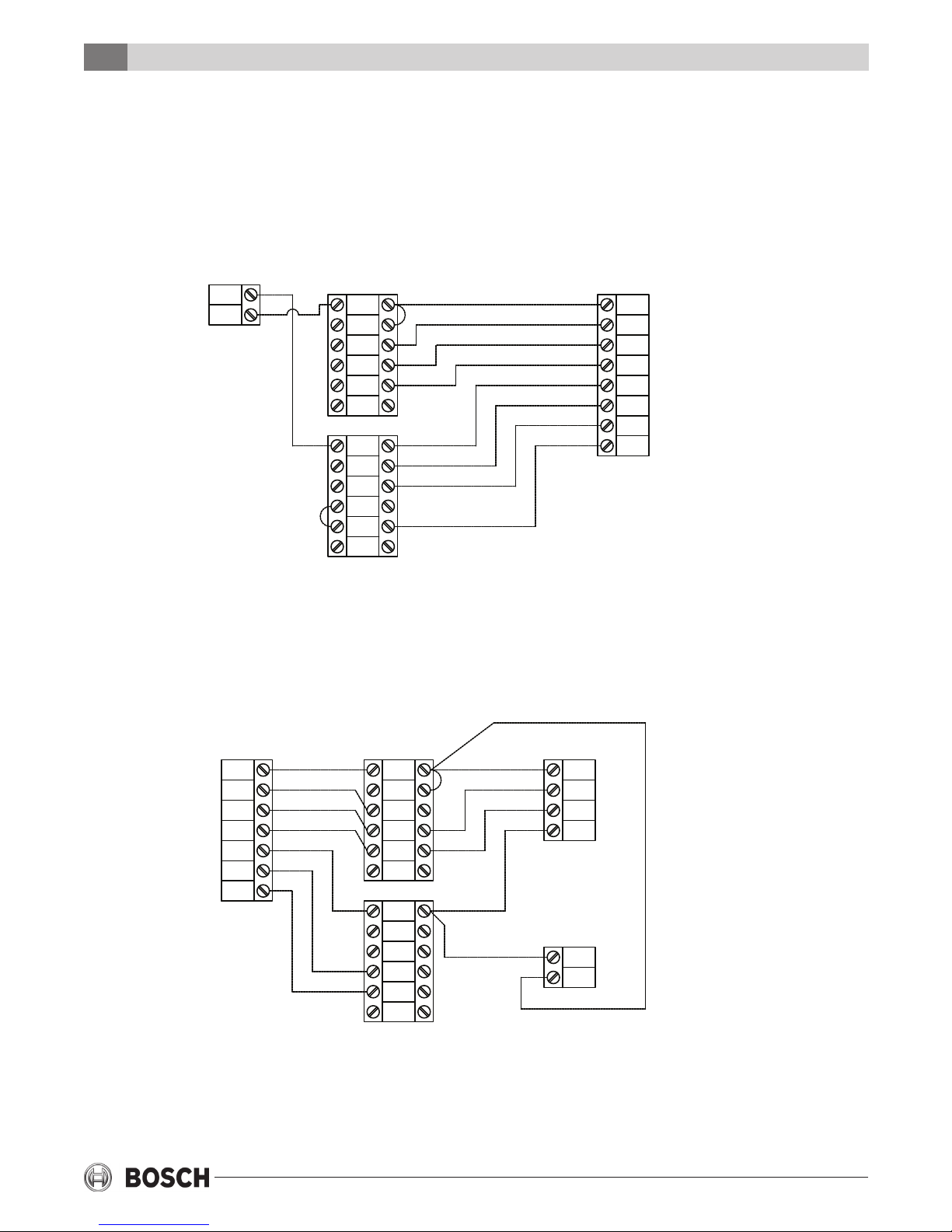
3H/2C SPLIT HEAT PUMP
9TSTBM3H2CPH6W-AWiring Schematics
FAN COIL / AIR
HANDLER
R
G
Y1
Y2
C
W1
W2/E
BASE MODULE
RH
RC
G
Y1
Y2
D
C
O
B
W1/E
W2
H
COMPRESSOR
SECTION
R
Y1
Y2
C
O
B
TSTBM3H2CPH6W-A
THERMOSTAT
C
R
3H/2C HEAT PUMP WITH GAS/OIL
FURNACE HEAT BACKUP
FAN COIL /
FURNACE
R
G
Y/Y1
Y2
C
W/W1
BASE MODULE
RH
RC
G
Y1
Y2
D
C
O
B
W1/E
W2
H
R
Y1
COMPRESSOR
SECTION
Y2
C
O
B
TSTBM3H2CPH6W-A
C
R
THERMOSTAT
Revised 02-13 Subject to change without prior notice
6 720 220 376
10 TSTBM3H2CPH6W-A
JUMP "E" & "W2" AT THE TSTBM3H2CPH6W-A
THERMOSTAT WHEN THE HEAT PUMP EQUIPMENT
DOES NOT HAVE AN EMERGENCY HEAT TERMINAL
TSTBM3H2CPH6W-A
THERMOSTAT
C
R
BASE MODULE
RH
RC
G
Y1
Y2
D
C
O
B
W1/E
W2
H
Wiring Schematics
PACKAGED
HEAT PUMP
R
G
Y1
Y2
C
O
B
W
2H/2C AIR CONDITIONING W/
ELECTRIC HEAT BACKUP
FAN COIL / AIR
HANDLER
R
G
Y1
Y2
C
W1
W2
BASE MODULE
RH
RC
G
Y1
Y2
D
C
O
B
W/E
W2
H
TSTBM3H2CPH6W-A
COMPRESSOR
SECTION
R
Y1
Y2
C
THERMOSTAT
C
R
6 720 220 376
Subject to change without prior notice Revised 02-13
 Loading...