

Page 1
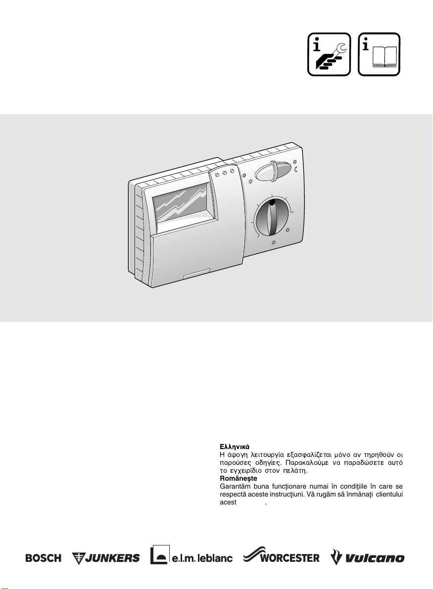
TR 200
Deutsch
Die einwandfreie Funktion ist nur gewährleistet, wenn diese
Anleitung beachtet wird. Wir bitten, diese Schrift dem Kunden auszuhändigen.
English
Correct function of this appliance can only be guaranteed if
these instructions are observed. Please hand this document
over to the customer.
Français
Un fonctionnement impeccable n’est assuré que si les instructions ci-après sont respectées. Nous vous prions de bien
vouloir les transmettre au client.
Español
Para garantizar un funcionamiento correcto es importante
atenerse a estas instrucciones de instalación. Por favor, entrégueselas al cliente.
Italiano
Soltanto attenendosi alle istruzioni presenti può essere garantito un perfetto funzionamento. Vi preghiamo di consegnare al cliente questo manuale.
Português
O perfeito funcionamento do aparelho só pode ser garantido, se esta instrução de serviço fôr observada com atenção.
Pedimos que este documento seja entregue ao cliente.
6 720 604 477 (00.12)
20°C
15
10
5
Nederlands
De juiste werking is alleen gewaarborgd wanneer deze gebruiksaanwijzing in acht wordt genomen. Wij verzoeken u,
dit document aan de klant te overhandigen.
Türkçe
Cihaz∂n kusursuz biçimde iµlev görmesi ancak bu k∂lavuza
uymakla mümkündür. Bu k∂lavuz, kullan∂c∂ya verilmelidir.
Dansk
En korrekt funktion kan kun sikres, hvis nærværende vejledning overholdes. Nærværende materiale bedes udleveret til
kunden.
∂ППЛУИО¿
∏ ¿„ФБЛ ПВИЩФ˘ЪБ›· ВН·ЫК·П›˙ВЩ·И МfiУФ ·У ЩЛЪЛıФ‡У ФИ
·ЪФ‡ЫВ˜ Ф‰ЛБ›В˜. ¶·Ъ·О·ПФ‡МВ У· ·Ъ·‰ТЫВЩВ ·˘Щfi
ÙÔ ÂÁ¯ÂÈÚ›‰ÈÔ ÛÙÔÓ ÂÏ¿ÙË.
Româneµte
Garantåm buna funcøionare numai în condiøiile în care se
respectå aceste instrucøiuni. Vå rugåm så înmânaøi clientului
acest prospect.
25
30
4477-00.2O
OSW
Page 2
TR 200
2
Page 3
TR 200
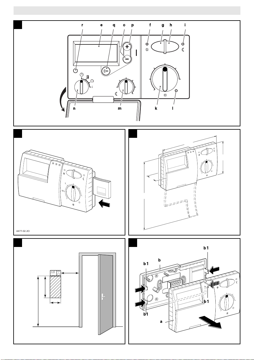
eopfghi
1
C
4477-01.1/O
qr
20°C
2515
15°C
10
5
20
25
5
30
3010
lkmn
2
4477-02.2O
4
0,6m
0,3m
1,2 - 1,5m
10
15
min.
0,3m
3
176
98
20°C
25
15
30
10
20°C
25
i
30
46
192
5
b
b1
b1
a
4477-05.2O
4192-03.1/G
5
4477-03.2O
b1
20°C
25
b1
15
10
30
5
3
Page 4
•
TR 200
Deutsch
1 Sicherheitshinweise ......................................................5
2 Anwendung ...................................................................5
3 Technische Daten ......................................................... 5
4 Montage ........................................................................5
5 Elektrischer Anschluß ................................................... 6
6 Bedienung .................................................................... 6
• Sprache einstellen..................................................... 12
7 Regler-Meldung .......................................................... 14
8 Allgemeine Hinweise ..................................................14
9 Fehlersuche ................................................................15
10 Individuelle Heizzeiten .............................................. 132
English
1 Safety Instructions ......................................................16
2 Application .................................................................. 16
3 Technical Data ............................................................ 16
4 Mounting .....................................................................16
5 Mains Connection ....................................................... 17
6 Operation ....................................................................17
• Setting the language ................................................. 23
7 Regulator Malfunction Message .................................25
8 General Information .................................................... 25
9 Elimination of malfunctions ......................................... 26
10 Individual Heating Times ..........................................132
Français
1 Instructions de sécurité ............................................... 27
2 Utilisation .................................................................... 27
3 Caractéristiques techniques .......................................27
4 Montage ......................................................................27
5 Branchement électrique .............................................. 28
6 Utilisation .................................................................... 29
• Sélectionner la langue............................................... 35
7 Message du thermostat ..............................................37
8 Conseils généraux ...................................................... 37
9 Recherche de pannes ................................................ 38
10 Temps de chauffage individuels ...............................132
Español
1 Instrucciones de seguridad ......................................... 39
2 Utilización ................................................................... 39
3 Datos técnicos ............................................................39
4 Instalación .................................................................. 40
5 Conexión eléctrica ......................................................40
6 Manejo ........................................................................41
• Selección del idioma ................................................. 46
7 Avisos del regulador ...................................................48
8 Indicaciones generales ............................................... 49
9 Búsqueda de averías .................................................. 50
10 Horas de calentamiento individuales ........................ 132
Italiano
1 Avvertenze ..................................................................51
2 Applicazione ............................................................... 51
3 Dati tecnici ..................................................................51
4 Montaggio ...................................................................51
5 Collegamento elettrico ................................................ 52
6 Messa in esercizio ......................................................52
• Impostare la lingua....................................................58
7 Segnalazioni del cronotermostato ambiente .............. 61
8 Informazioni generali ..................................................61
9 Ricerca di anomalie ....................................................62
10 Tempi di riscaldamento individuali ............................ 132
Portugues
1 Indicações de segurança ............................................ 63
2 Aplicação .................................................................... 63
3 Dados técnicos ...........................................................63
4 Montagem ...................................................................63
5 Ligação eléctrica ......................................................... 64
6 Comando .................................................................... 65
• Ajustar o idioma ........................................................ 70
7 Indicação do regulador ...............................................72
8 Indicações gerais ........................................................ 73
9 Procura de avarias ..................................................... 74
10 Horários individuais de aquecimento ........................ 132
4
Nederlands
1 Veiligheidsvoorschriften ..............................................75
2 Gebruik .......................................................................75
3 Technische gegevens .................................................75
4 Montage ...................................................................... 75
5 Elektrische aansluiting ................................................76
6 Bediening .................................................................... 77
• Taal instellen .............................................................82
7 Melding van de regelaar .............................................84
8 Algemene opmerkingen ..............................................85
9 Fouten opsporen .........................................................86
10 Afzonderlijke verwarmingstijden ...............................132
Türkçe
1 Emniyet Kurallar∂ ........................................................87
2 Kullan∂m Sahas∂ .......................................................... 87
3 Teknik Özellikler .........................................................87
4 Montaj .........................................................................87
5 Elektrik Baπlant∂s∂ .......................................................88
6 Termostat∂n Kullan∂m∂/ Kumandas∂ ............................88
Lisan∂n Programlanmas∂............................................ 94
7 Kombiden Termostata Ar∂za Bildirimi .........................96
8 Genel Aç∂klamalar ......................................................96
9 Hata Arama ................................................................. 97
10 Is∂tma Program∂ ........................................................132
Dansk
1 Sikkerhedsforskrifter ................................................... 98
2 Anvendelse ................................................................. 98
3 Tekniske data .............................................................98
4 Montering .................................................................... 98
5 Elektrisk tilslutning ......................................................99
6 Betjening ..................................................................... 99
• Indstilling af sprog....................................................105
7 Termostat-melding .................................................... 106
8 Almindelige råd .........................................................107
9 Fejlsøgning ...............................................................108
10 Individuelle varmetider ..............................................132
∂ППЛУИО¿
1 Àԉ›ÍÂȘ ·ÛÊ¿ÏÂÈ·˜ .............................................109
2 ÃÚ‹ÛË .......................................................................109
3 TВ¯УИО¿ ¯·Ъ·ОЩЛЪИЫЩИО¿ ..........................................109
4 ∂ÁηٿÛÙ·ÛË ............................................................109
5 ∏ПВОЩЪИО‹ Ы‡У‰ВЫЛ .................................................110
6 ГВИЪИЫМfi˜ ..................................................................111
•
¶ЪФБЪ·ММ·ЩИЫМfi˜ БПТЫЫ·˜ ..................................116
7 ª‹У˘М· ıВЪМФЫЩ¿ЩЛ ................................................118
8 °ÂÓÈΤ˜ ˘Ô‰Â›ÍÂȘ ..................................................119
9 ¢È¿ÁÓˆÛË Ï·ıÒÓ ......................................................120
10 ∞ЩФМИОФ› ¯ЪfiУФИ ı¤ЪМ·УЫЛ˜ ....................................132
Româneste
1 Recomandåri privind siguranøa .................................121
2 Utilizare .....................................................................121
3 Date tehnice .............................................................. 121
4 Montare .....................................................................121
5 Racorduri electrice ....................................................122
6 Deservire ..................................................................122
• Selectarea limbi .......................................................127
7 Semnalizarea regulatorului .......................................129
8 Recomandåri de ordin general .................................130
9 Detectarea defecøiunilor ............................................131
10 Timpi de încålzire individuali .....................................132
Page 5
TR 200
1 Sicherheitshinweise
Der Regler darf ausschließlich in Verbindung mit den aufgeführten Gasheizgeräten verwendet werden, der entsprechende Anschlußplan ist zu beachten.
Keinesfalls darf der Regler an das
230-V-Netz angeschlossen werden.
Vor der Montage des Reglers muß die
Spannungsversorgung (230 V, 50 Hz)
zum Heizgerät unterbrochen werden.
Der Regler ist nicht für die Montage in
Feuchträumen geeignet.
2 Anwendung
Der TR 200 ist ein Raumtemperaturregler mit
Digitalschaltuhr (Wochenprogramm; drei
Heiz- und drei Absenkschaltpunkte je Wochentag) zur Regelung der unten aufgeführten stetiggeregelten Gas-Heizgeräte.
TYP Elektr.
ZE/ZWE .. - 2 K... Bild nein
ZE/ZWE .. - 2 A... Bild
ZR/ZWR/ZSR...-3 Bild
ZR/ZWR/ZSR...-4 Bild
Heizgeräte mit
Bosch Heatronic Bild
Der TR 200 wird bei Wohnflächen bis ca.
2
80 m
empfohlen und entspricht den gesetzli-
Anschluß
10
nein
10
nein
10
nein
11
ja
chen Vorschriften.
Für Anlagen mit Fußbodenheizung sind
Raumtemperaturregler wie der TR 200 nicht
geeignet. In diesen Anlagen empfehlen wir
eine witterungsgeführte Regelung.
2.1 Lieferumfang
Zum Lieferumfang des TR 200 gehört der
Raumtemperaturregler mit eingeschobener
Kurzbedienungsanleitung (
9
Bild ).
Fernstöranzeige aktiv
2
2.2 Zubehör
Zum TR 200 ist ein externer Raumtemperaturfühler RF 1 lieferbar. Dieser ist zum Beispiel dann sinnvoll einzusetzen, wenn der
Montageort des Reglers zur Temperaturmessung ungeeignet ist (siehe Kapitel 4).
Weiterhin kann
bauseits
ein Fernschalter
(z. B in Form eines Telefoncommanders) angeschlossen werden (siehe Kapitel 6.8).
Der Fernschalter muß einen potentialfreien
Kontakt enthalten, der für 5 V DC geeignet ist.
3 Technische Daten
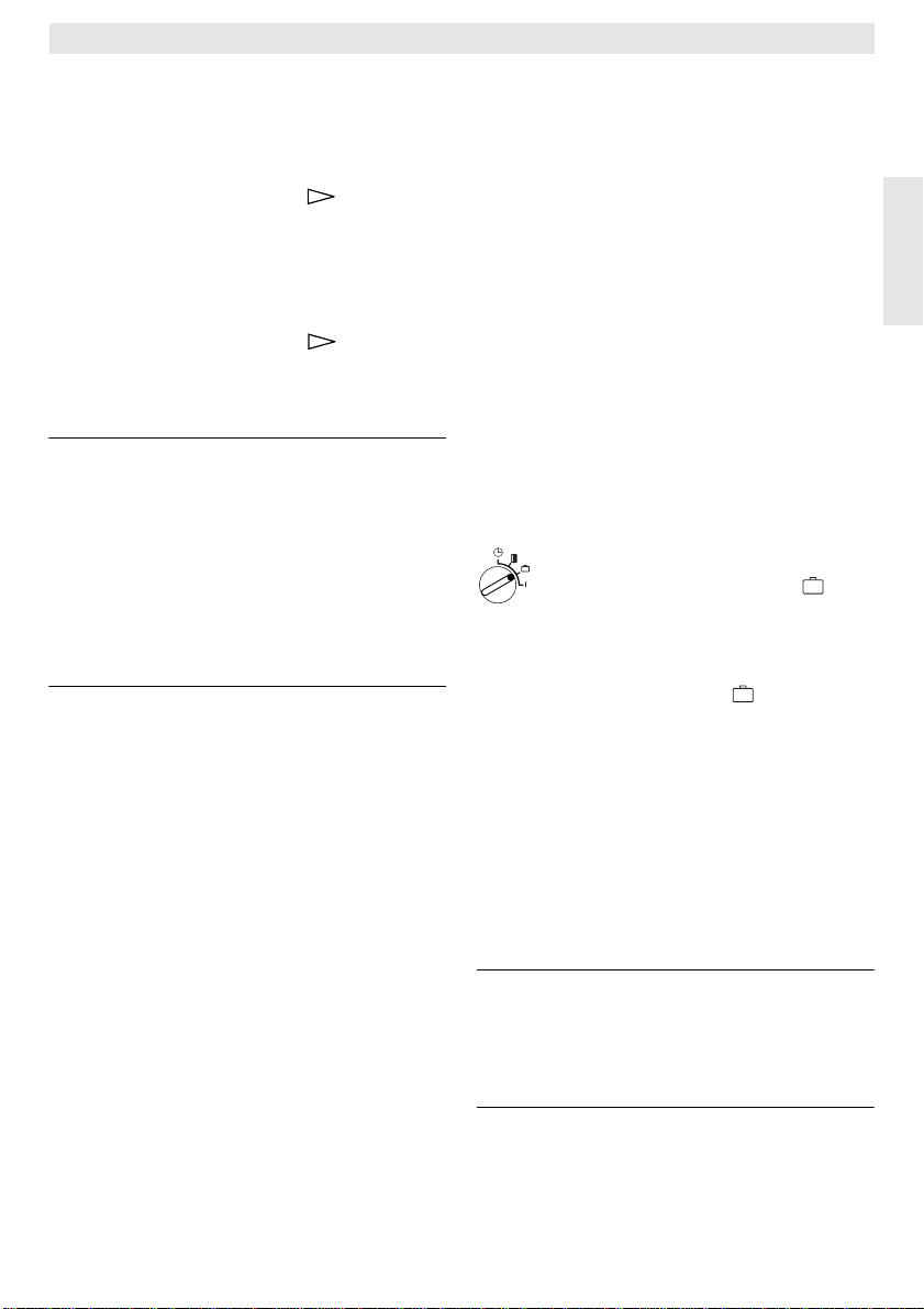
Geräteabmessungen
Nennspannung 24 V DC
Nennstrom 0,03 A
Regelbereich 5…30 °C
Regelausgang stetig, 2,8…21,5 V DC
zulässige
Umgebungstemperatur 0…+40 °C
Gangreserve ca. 2 Stunden
Schutzart IP 20
siehe Bild
3
4 Montage
Vor der Montage des Reglers muß die
Spannungsversorgung (230 V, 50 Hz)
zum Heizgerät unterbrochen werden.
4.1 Wahl des Montageortes
Wichtig für die Regelqualität des TR 200 ist
die Wahl eines geeigneten Montageortes. Der
Montageraum muß für die Temperaturregelung der gesamten Heizungsanlage geeignet
sein. An den dort installierten Heizkörpern
dürfen keine Thermostatventile montiert sein.
Statt dessen sollten Handventile mit Voreinstellung eingebaut sein, damit die Leistung
der Heizkörper im Montageraum des TR 200
so knapp wie möglich einstellbar ist.
Als Montageort möglichst eine Innenwand
wählen und darauf achten, daß weder Zugluft
noch Wärmestrahlung (auch nicht von hinten,
z. B. durch Leerrohr, Hohlwand usw.) auf den
Regler einwirken kann.
Deutsch
5
Page 6
TR 200
Unterhalb und oberhalb des Reglers muß
ausreichend Platz vorhanden sein, damit die
Raumluft ungehindert durch die Lüftungsöffnung zirkulieren kann (schraffierte Fläche in
4
Bild ).
Deutsch
Sind die oben genannten Bedingungen nicht
alle erfüllt, so wird empfohlen, den externen
Raumtemperaturfühler RF 1 (Zubehör) einzusetzen und diesen an einer geeigneteren Stelle anzubringen.
Beim Anschluß des Raumtemperaturfühlers
RF 1 wird automatisch der im Regler eingebaute Fühler abgeschaltet.
4.2 Montage des Reglers
• Das Oberteil
liche Haken
Oberteil
• Der Sockel
– mit zwei Schrauben
delsübliche Unterputzdose
(a)
vom Sockel
(b1)
am Sockel eindrücken und
(a)
abziehen (Bild ).
(b)
kann wahlweise
(b)
lösen, seit-
5
(c)
auf eine han-
(d)
mit
ø 55 mm montiert werden,
oder
– mit 4 Dübeln (6 mm) und Schrauben
(Ø 3,5 mm) Linsenkopf direkt an die
Wand geschraubt werden (Bild );
6
dabei auf die richtige Montagerichtung achten (Klemmenbeschriftung lesbar)!
• Elektrischen Anschluß entsprechend ausführen (siehe Kapitel 5).
• Regleroberteil
(a)
aufstecken.
4.3 Montage des Zubehörs
Die Zubehöre externer Raumtemperaturfühler
RF 1 und Fernschalter (falls vorhanden) entsprechend den gesetzlichen Vorschriften und
der zugehörigen Einbauvorschrift montieren.
5 Elektrischer Anschluß
Folgender Leitungsquerschnitt ist vom
TR 200 zum Heizgerät zu verwenden:
Länge bis 20 m 0,75 mm
Länge bis 30 m 1,0 mm
2
bis 1,5 mm
2
bis 1,5 mm
Länge über 30 m 1,5 mm
Unter Berücksichtigung der geltenden Vorschriften müssen für den Anschluß mindestens Elektrokabel der Bauart H05 VV... eingesetzt werden.
6
Alle 24-V-Leitungen (Meßstrom) müssen von
230 V oder 400 V führenden Leitungen getrennt verlegt werden, damit keine induktive
Beeinflussung stattfindet (Mindestabstand
100 mm).
Sind induktive äußere Einflüsse z. B. durch
Starkstromkabel, Fahrdrähte, Trafostationen,
Rundfunk- und Fernsehgeräte, Amateurfunkstationen, Mikrowellengeräte o. ä. zu erwarten, so sind die Meßsignal führenden Leitungen geschirmt auszuführen.
Es ist der entsprechende elektrische Anschlußplan (Bild bis ) zu befolgen.
9 11
5.1 Elektrischer Anschluß des Zubehörs
Externer Raumtemperaturfühler RF 1 (falls
vorhanden) wie im Bild dargestellt an-
7
schließen.
Bei Bedarf können die Leitungen des RF 1 mit
einem Kabel mit verdrillten Zwillingsleitungen
verlängert werden. Dadurch wird sichergestellt, daß die Meßwerte des Fühlers nicht beeinflußt werden.
Fernschalter (falls bauseits vorhanden) wie im
8
Bild dargestellt anschließen. Erforderliche
Mindestanforderungen siehe Kapitel 2.2 Zubehör.
Bei geschlossenem Schaltkontakt des Fernschalters geht die Heizung auf Sparbetrieb.
Bei geöffnetem Schaltkontakt wird die am
Regler eingestellte Betriebsart übernommen
8
(
Bild ).
6 Bedienung
Der TR 200 besitzt einige Bedienelemente,
die nach Installation und Inbetriebnahme nur
noch selten benutzt werden müssen.
Deshalb sind alle Bedienelemente, die nur
wenig benutzt werden, mit einer Klappe abgedeckt.
Die bei geschlossener Klappe sichtbaren Bedienelemente gehören zur sogenannten
2
„1. Bedienebene“. Alle anderen Bedienele-
2
mente bilden die „2. Bedienebene“ und „3. Be-
2
dienebene“ bzw. „Serviceebene“ für den
Fachmann.
Alle Sonder-Betriebszustände werden durch
Text in der Anzeige oder Kontrolleuchten angezeigt, ebenso die Störanzeige (nur bei den
Heizgeräten mit Bosch Heatronic).
Page 7
TR 200
Bei geschlossener Klappe wird die aktuelle
Uhrzeit und die gemessene Raumtemperatur
(in 0,5-°C-Schritten) angezeigt.
6.1 Die „1. Bedienebene“
20°C
15
25
3010
5
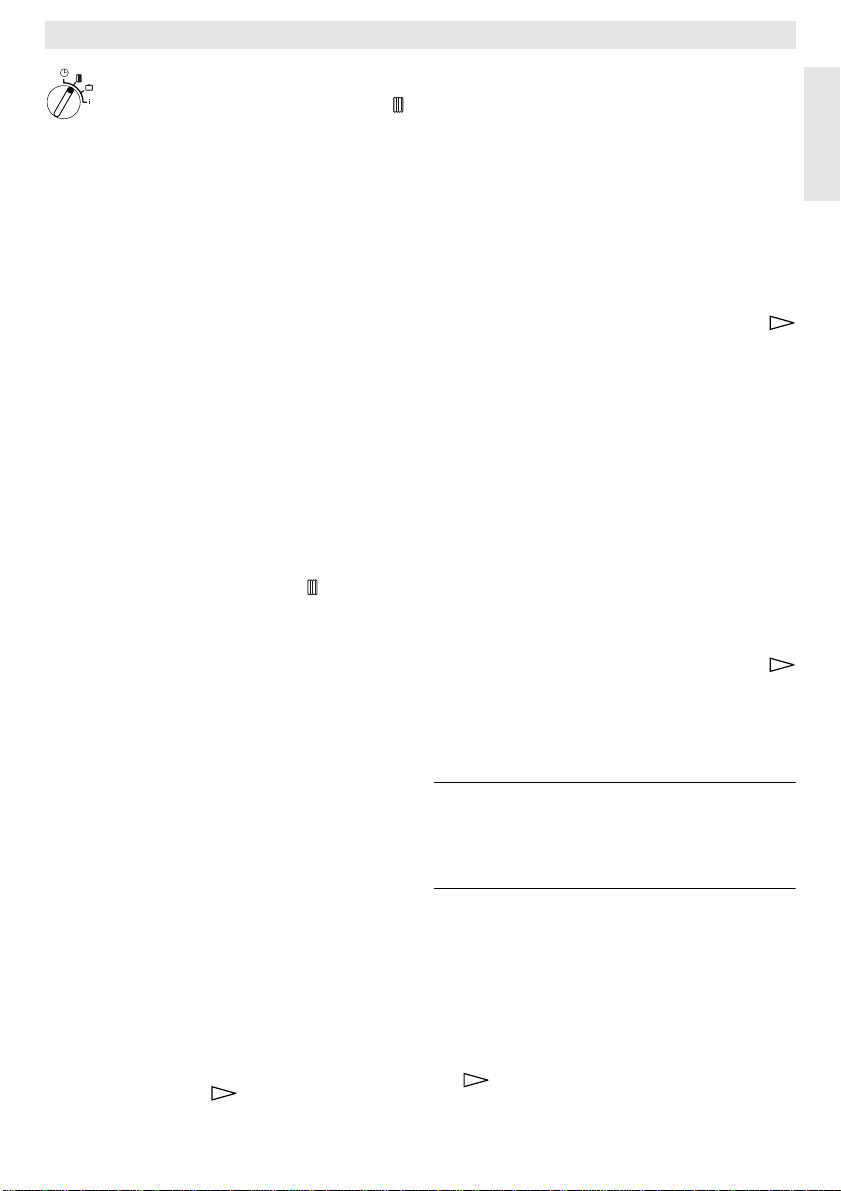
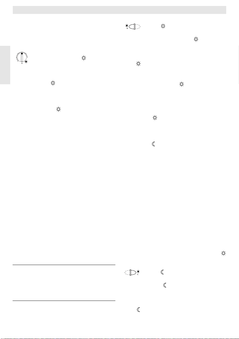
Am Drehknopf
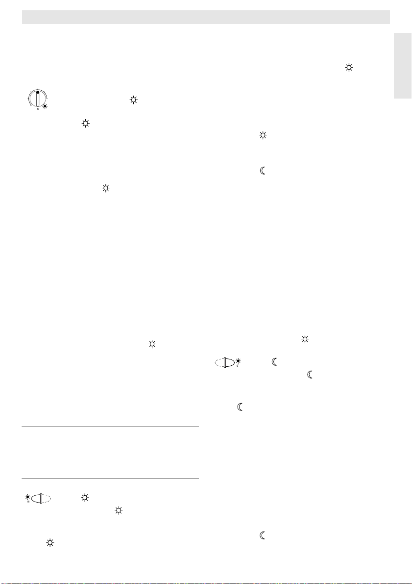
6.1.1 Drehknopf „Heizen“ (k)
(k)
wird die Raumtemperatur eingestellt, auf die der Regler im normalen
Heizbetrieb regeln soll.
Der Regler regelt immer dann auf diese Temperatur, wenn die zugehörige rote Kontrolleuchte
Steht der Drehknopf
zugehörige rote Kontrolleuchte
(l)
leuchtet.
(k)
auf „5“, leuchtet die
(l)
nicht. Der
Regler regelt dann auf etwa 5 °C und gewährleistet damit Frostschutz im Raum. D. h. die
Heizung ist oberhalb von 6 °C ausgeschaltet.
6.1.2 Die Betriebszustände
Automatikbetrieb
Die Grundeinstellung des Reglers ist Automatikbetrieb.
Automatikbetrieb bedeutet automatischer
Wechsel zwischen normalem Heizbetrieb und
Sparbetrieb zu den von der Schaltuhr
(e)
vor-
gegebenen Zeiten.
Der Regler regelt im normalen Heizbetrieb
(=„Tag“) auf die am Drehknopf
(k)
eingestellte Temperatur, die zugehörige rote Kontrolleuchte
(l)
leuchtet dauernd.
Der Regler regelt im Sparbetrieb (=„Nacht“)
auf die eingestellte Spartemperatur, die zugehörige rote Kontrolleuchte
(l)
leuchtet nicht.
(Einstellung der Spartemperatur siehe
Kapitel 6.2.1)
Hinweis: Jedes Verlassen der Automatik wird
durch eine Kontrollampe oder Text
angezeigt.
Es kann jederzeit zum Automatikbetrieb zurück gekehrt werden.
Taste „Dauerheizen“ (g)
Ein Druck auf die Taste (g) schaltet die Betriebsart Dauerheizen ein.
Der Regler regelt dauernd auf die am Drehknopf
(k)
eingestellte Temperatur.
Die zugehörige rote Kontrolleuchte (f) leuchtet.
Ebenso leuchtet die zugehörige rote Kontrolleuchte
(l)
(außer der Drehknopf
(k)
steht
auf Stellung „5“).
Der an der Schaltuhr eingestellte Sparbetrieb
wird ignoriert.
Die Betriebsart „Dauerheizen“ bleibt so lange
bestehen, bis:
• die Taste
(g)
nochmals gedrückt wird; es
ist dann wieder Automatikbetrieb eingestellt
oder
• die Taste
(h)
gedrückt wird; es ist dann
Sparbetrieb eingestellt.
In beiden Fällen erlischt die zugehörige rote
Kontrolleuchte
(f)
und der Regler heizt ent-
sprechend der dann gültigen Temperatur.
Tip
Drücken Sie diese Taste, wenn Sie aus-
☞
nahmsweise später zu Bett gehen (z. B. Party). Später wieder auf Automatikbetrieb
zurückschalten.
Auch bei Krankheit kann Dauerheizen angenehm sein. Vergessen Sie aber auch dann
nicht, auf Automatikbetrieb zurückzuschalten.
Während des Winterurlaubs oder im Sommer
kann für längere Zeit eine niedrigere Heiztemperatur gewählt werden, indem man die Taste
Dauerheizen drückt und zusätzlich die Temperatur am Drehknopf
(k)
absenkt.
Taste „Sparbetrieb“ (h)
Ein Druck auf die Taste (h) schaltet die Betriebsart Sparbetrieb ein.
Der Regler regelt dauernd auf die am Drehknopf
(m)
eingestellte Temperatur (Einstel-
lung der Spartemperatur siehe Kapitel 6.2.1).
Die zugehörige gelbe Kontrolleuchte
(i)
leuch-
tet.
Die zugehörige rote Kontrolleuchte
(l)
ist aus.
Der an der Schaltuhr eingestellte normale
Heizbetrieb wird ignoriert.
Die Betriebsart „Sparbetrieb“ bleibt bestehen,
bis
•
Mitternacht
(00.00 Uhr)
oder
• die Taste
(h)
nochmals gedrückt wird; es
ist dann wieder Automatikbetrieb eingestellt
Deutsch
7
Page 8
oder
• die Taste
Dauerheizen eingestellt.
In allen Fällen erlischt die zugehörige gelbe
Kontrolleuchte
Deutsch
sprechend den dann gültigen Temperaturen.
Tip
Verwenden Sie diese Funktion, wenn
☞
Sie die Wohnung ausnahmsweise verlas-
(g)
gedrückt wird; es ist dann
(i)
und der Regler heizt ent-
sen (z. B. beim Einkaufen) und die Wohnung
nicht mehr beheizt werden soll. Sobald Sie zurückkommen drücken Sie die Taste
(h)
neut, der Regler arbeitet wieder im
Automatikbetrieb und heizt entsprechend der
dann gültigen Temperatur.
Wenn Sie die
oder einmal
Sie die Taste
Wohnung abends verlassen
früher zu Bett gehen
(h)
. Der Regler beendet um
, drücken
Mitternacht den Sparbetrieb und heizt am
nächsten Morgen wie gewohnt im Automatikbetrieb.
6.2 Die „2. Bedienebene“
Die „2. Bedienebene“ wird nach Öffnen der
Klappe zugänglich.
Mit dem Öffnen der Klappe wird automatisch
der Programmiermodus eingestellt. Die Anzeige richtet sich nach der Stellung des Drehschalters
10
5
(n)
.
15°C
20
25
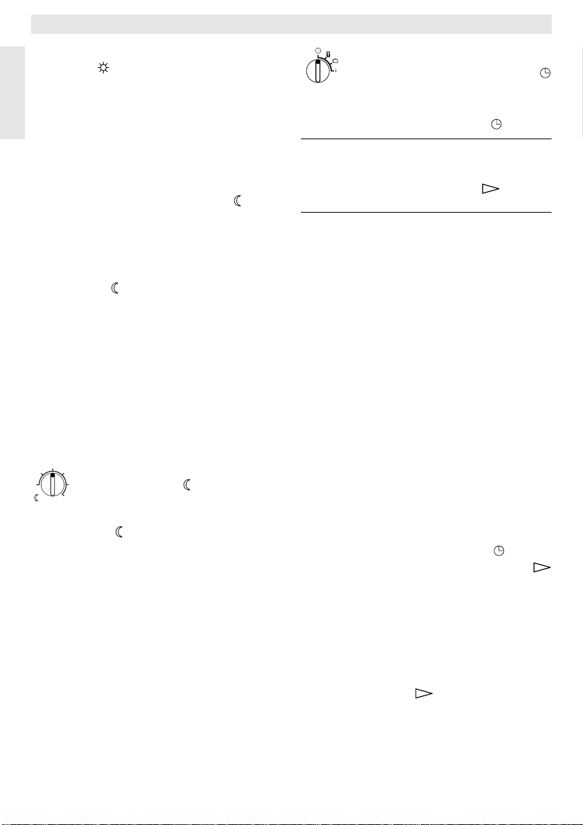
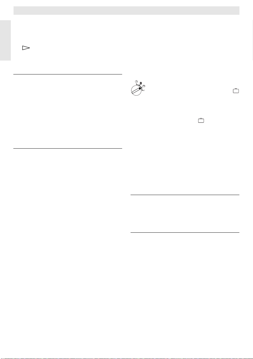
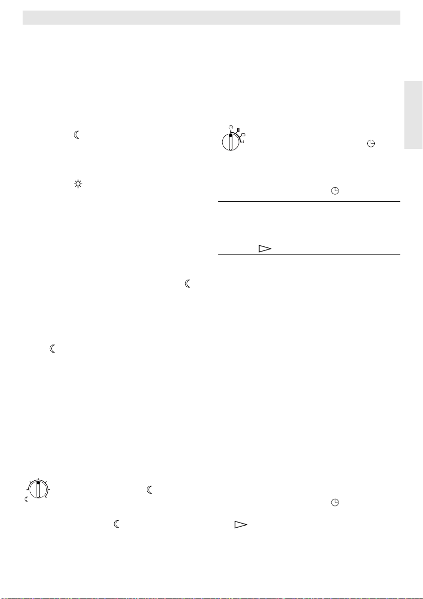
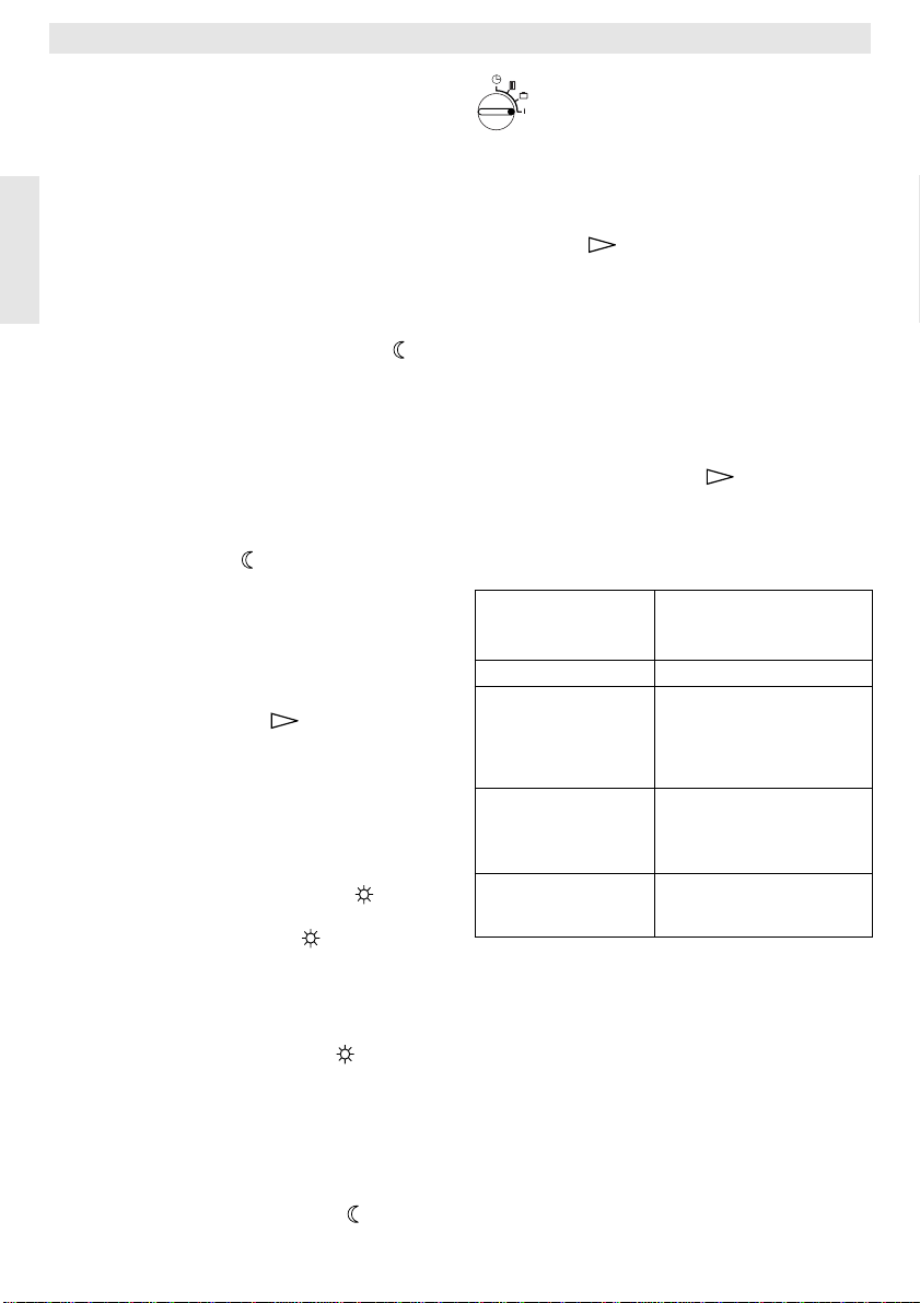
6.2.1 Drehknopf
30
„Spartemperatur“ (m)
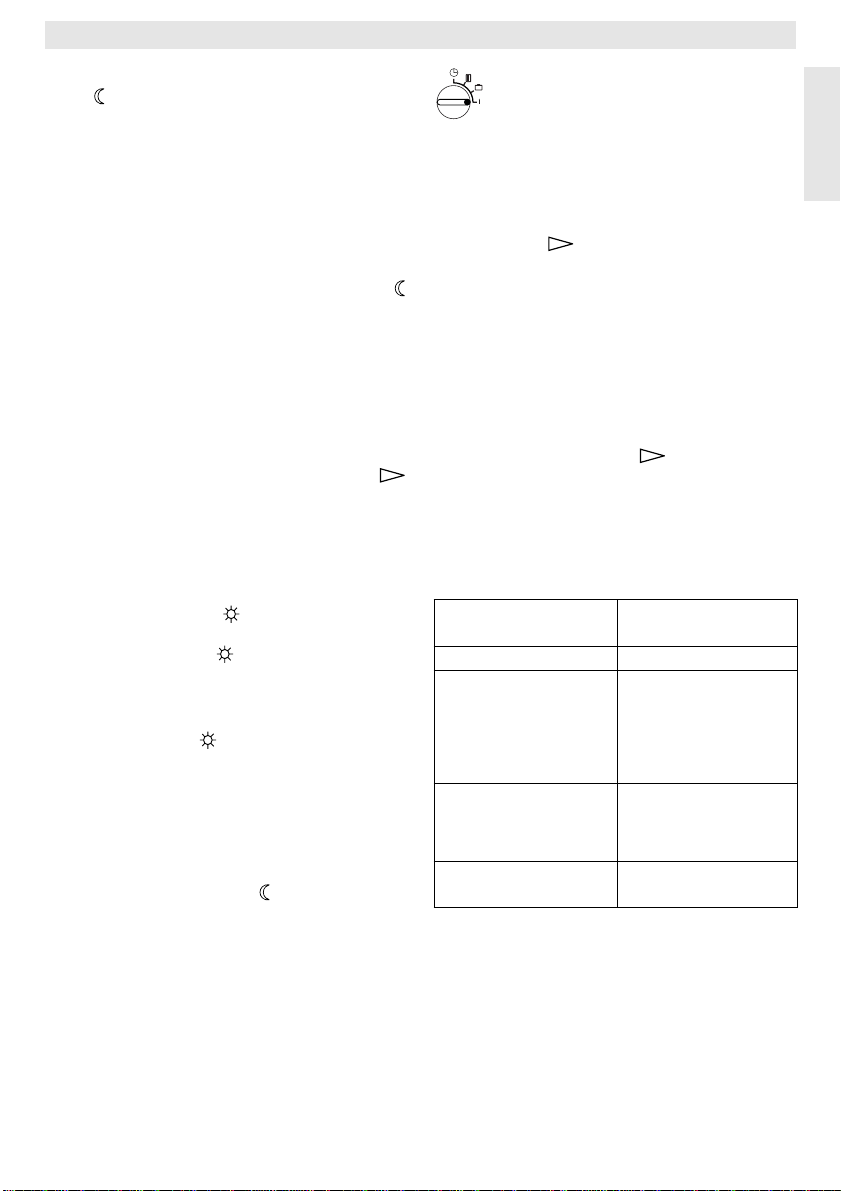
6.2.3 Drehschalter in Stellung
„Uhr stellen“
Uhrzeit einstellen
Den Drehschalter (n) auf Stellung drehen.
Hinweis: Bei Inbetriebnahme oder längerem
er-
In der Anzeige (e) erscheint:
Stromausfall erscheint
In diesem Fall aktuellen Wochentag
einstellen, dann Taste (q) drükken.
Uhr stellen +/12:00
Die Uhrzeit wird durch Drücken der Tasten „–“
(o) oder „+“ (p) eingestellt.
Ein kurzer Druck verstellt die Uhrzeit um 1 Minute, bei längerem Drücken läuft die Zeit
schnell weiter oder zurück. Dabei werden die
Sekunden jeweils auf „0“ gestellt. Sobald die
Taste losgelassen wird, läuft die Zeit „normal“
weiter.
Tip
Uhrzeiten vor 12.00 (Mittags) lassen
☞
sich mit der „–“Taste (o) schneller einstellen.
Klappe schließen, wenn keine weiteren Änderungen vorgenommen werden sollen.
In der Anzeige (e) erscheint:
17:53 21.5°C
TR 200
Tag wählen +/-.
Am Drehknopf
tur eingestellt, auf die der Regler im Automatikbetrieb bei „Sparen“ und im „Sparbetrieb“
(h)
regeln soll.
6.2.2 Allgemeines zur Uhr
Die Schaltuhr ermöglicht, bis zu drei mal am
Tag die Heizung zu einem festgelegten Zeitpunkt automatisch einschalten zu lassen und
drei mal am Tag die Heizung zu einem festgelegten Zeitpunkt automatisch ausschalten zu
lassen.
Diese Zeitpunkte können für jeden Tag einzeln festgelegt werden.
(m)
wird die Raumtempera-
8
Wochentag einstellen
Den Drehschalter (n) auf Stellung drehen.
Wenn
Uhr stellen +/- angezeigt wird, Taste
(q) drücken. In der oberen Zeile der Anzeige
(e) erscheint:
Tag wählen +/-
Der aktuelle Wochentag wird durch Drücken
der Tasten „–“ (o) oder „+“ (p) eingestellt.
Soll anschließend die Uhrzeit eingestellt werden, dann die Taste (q) drücken.
Klappe schließen, wenn keine weiteren Änderungen vorgenommen werden sollen.
Page 9
TR 200
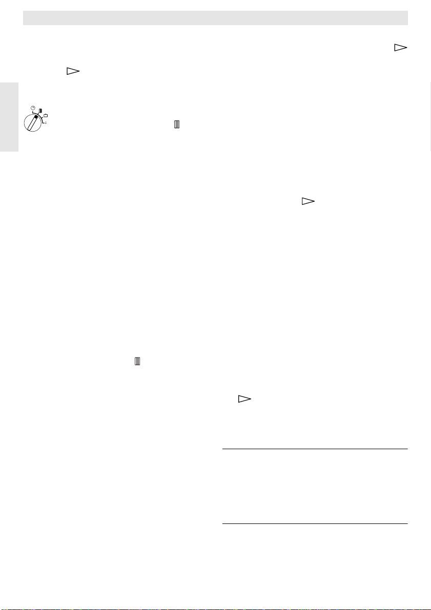
6.2.4 Drehschalter in Stellung
„Heizung“
In der Anzeige (e) erscheint:
1. Heizbeginn
6:00
Heizprogramm einstellen
Die Schaltuhr ermöglicht, bis zu drei mal am
Tag die Heizung zu festgelegten Zeitpunkten
automatisch einschalten zu lassen und bis zu
drei mal am Tag die Heizung zu festgelegten
Zeitpunkten automatisch ausschalten zu lassen.
Diese Zeitpunkte können für jeden Tag einzeln festgelegt werden.
Ebenso ist es möglich, daß für jeden Tag die
gleichen Zeiten eingestellt werden.
Um effektiv programmieren zu können, ist es
sinnvoll, die Heizzeiten in die Tabelle (siehe
Kapitel 10) einzutragen. Das Heizprogramm,
das an den meisten Tagen (auch in leicht abgewandelter Form) vorkommt, sollte dann im
ersten Schritt für alle Tage eingegeben werden. Die abweichenden Zeiten lassen sich danach ohne großen Aufwand verändern.
Den Drehschalter (n) in Stellung drehen. In
der Anzeige (e) erscheint:
Tag wählen +/-
Taste „–“ (o) oder „+“ (p) drücken. Es erscheint
chentag) in der oberen Zeile.
In der Einstellung
Tag um die gleiche Zeit mit „Heizen“ begonnen und jeden Tag um die gleiche Zeit mit
„Sparen“ begonnen.
Wurde ein einzelner Wochentag (z. B. Donnerstag) gewählt, so wird immer an diesem
Wochentag zur vorgegebenen Zeit das zugehörige Programm gültig. D. h. es wird jeden
Donnerstag um die gleiche Zeit mit „Heizen“
oder mit „Sparen“ begonnen.
Ein einzelner Wochentag wird durch Drücken
der Tasten „–“ (o) oder „+“ (p) eingestellt.
Zwischen
alle Wochentage angezeigt.
Für den angezeigten Wochentag/alle Wochentage können die Heizzeiten eingestellt
werden. Dazu Taste (q) drücken.
alle Wochentage (oder der aktuelle Wo-
alle Wochentage wird jeden
Sonntag und Montag wird
Der gewünschte erste Heizbeginn wird durch
Drücken der Tasten „–“ (o) oder „+“ (p) eingestellt.
Ein kurzer Druck verstellt den Zeitpunkt für
Heizbeginn um 10 Minuten, bei längerem
Drücken läuft der Zeitpunkt schnell weiter
oder zurück.
Ist die gewünschte Zeit eingestellt, Taste
(q) drücken.
Nun muß der zugehörige erste Sparbeginn
eingestellt werden.
In der Anzeige (e) erscheint:
1. Sparbeginn
22:00
Der gewünschte erste Sparbeginn wird durch
Drücken der Tasten „–“ (o) oder „+“ (p) eingestellt.
Ein kurzer Druck verstellt den Zeitpunkt für
Sparbeginn um 10 Minuten, bei längerem
Drücken läuft der Zeitpunkt schnell weiter
oder zurück.
Ist die gewünschte Zeit eingestellt, Taste
(q) drücken.
In der Anzeige (e) erscheint:
2. Heizbeginn
--:--
Hinweis: --:-- bedeutet, daß dieser Schalt-
punkt nicht belegt ist, d. h. bei
Werkseinstellung oder nach längerem Stromausfall ist nur ein Heizbeginn und ein Sparbeginn eingestellt.
Jetzt kann, wenn gewünscht, die Zeit für den
zweiten Heizbeginn nach dem gleichen Schema wie für den ersten Heizbeginn eingestellt
werden.
Für den zweiten Sparbeginn, sowie wenn gewünscht, für den dritten Heiz- und Sparbeginn
ebenso vorgehen.
Werden Schaltpunkte nicht benötigt, die Taste (q) drücken, ohne etwas zu verstellen.
Deutsch
9
Page 10
TR 200
Soll ein angezeigter Schaltpunkt gelöscht
werden, die Löschtaste C (r) mit einem Stift
kurz drücken. Es erscheint
Sind die gewünschten Zeiten eingestellt, Taste (q) drücken.
Deutsch
Es erscheint
schrieben einen einzelnen/anderen Tag auswählen und die zugehörigen Zeiten eingeben.
Hinweis: Wurde nach der Programmierung
Tip
Die Schaltpunkte eines Tages brauchen
☞
nicht in der zeitlich richtigen Reihenfolge ein-
Tag wählen +/-. Nun wie oben be-
für alle Wochentage, ein einzelner
Wochentag verändert, erscheint
nach erneutem Aufruf von Programmierpunkt „
Schaltpunkten
Wird dann ein Schaltpunkt für alle
Wochentage verändert, wird das ursprüngliche Programm der einzelnen Wochentage gelöscht und muß
wie oben beschrieben wieder neu
programmiert werden.
--:-- in der Anzeige.
alle Wochentage“ bei allen
--:-- in der Anzeige.
gegeben werden. Während der Anzeige
wählen +/-
ordnet der Regler die Schaltpunkte
selbständig.
Sie können die eingestellten Schaltpunkte an-
sehen, indem Sie wie oben beschrieben vorgehen, jedoch ohne „–“ (o) oder „+“ (p) zu
drücken.
Soll über Mitternacht hinaus geheizt wer-
den, so entfällt der letzte Sparbeginn. Diesen
am darauffolgenden Tag als 1. Sparbeginn
eingeben. Der Regler erkennt die Reihenfolge
der Schaltpunkte, obwohl der 1. Heizbeginn
später liegt als der 1. Sparbeginn.
Soll an einem Wochentag grundsätzlich nicht
geheizt werden (z. B. Büro, das Sonntags
nicht benutzt wird), so geben Sie den zugehörigen Sparbeginn (ggf. am Vortag) ein, und löschen alle weiteren Schaltpunkte, bis wieder
geheizt werden soll.
Soll an einem Wochentag grundsätzlich
durchgehend geheizt werden, so geben Sie
den zugehörigen Heizbeginn (ggf. am Vortag)
ein, und löschen alle weiteren Schaltpunkte,
bis wieder gespart werden soll.
Möchten Sie am Programm umfangreiche
Änderungen durchführen, ist es evt. günstiger, vom werkseitig eingestellten Programm
auszugehen.
Um alle persönlichen Schaltpunkte zu lö-
schen, gehen Sie wie oben beschrieben vor,
bis die Anzeige
ken Sie dann kurz die Löschtaste C (r).
Dann ist wieder die Werkseinstellung (Alle Tage: 1. Heizbeginn 06:00; 1. Sparbeginn 22:00,
weitere Schaltpunkte
Klappe schließen, wenn keine weiteren Änderungen vorgenommen werden sollen.
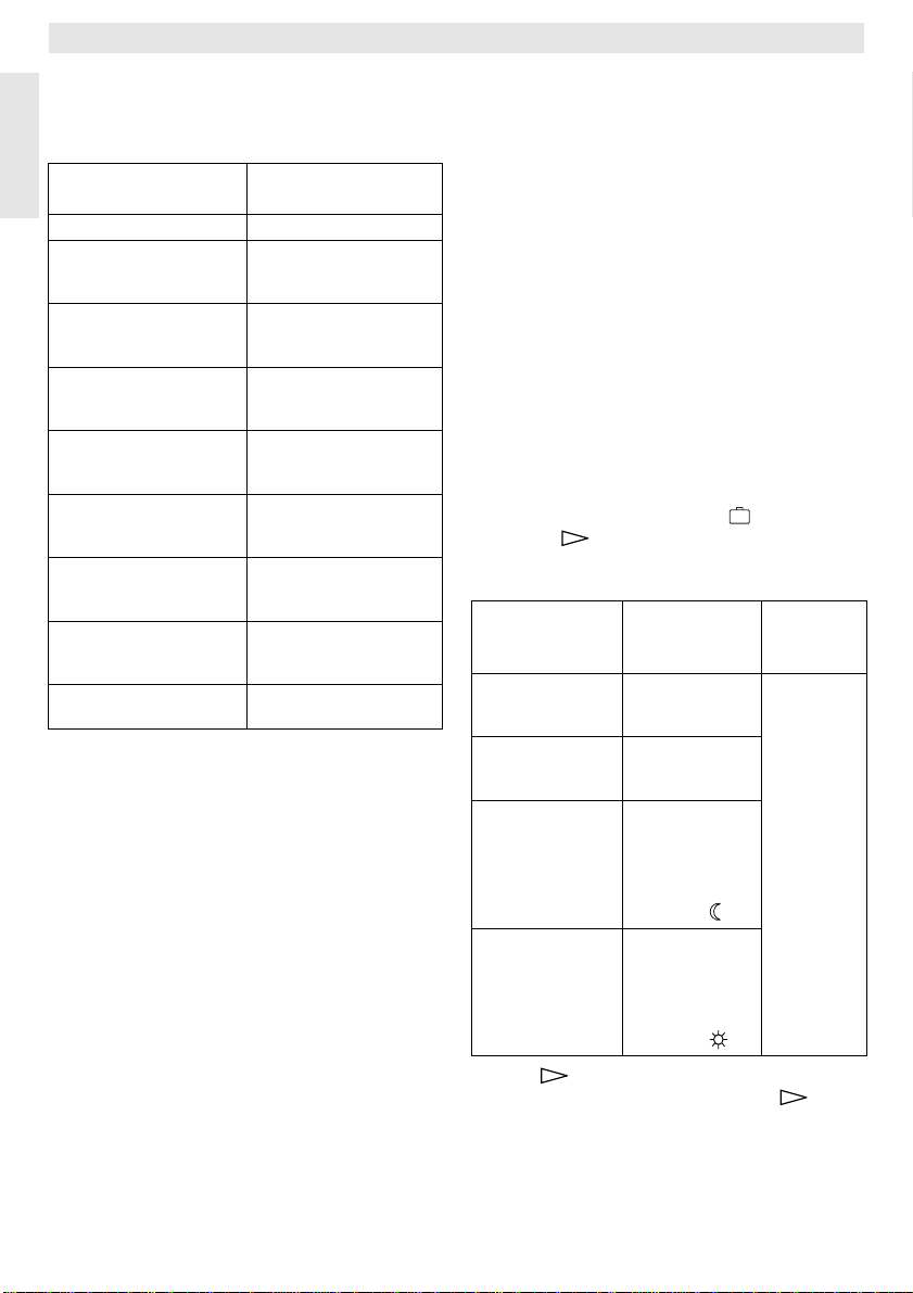
Urlaub einstellen
Drehschalter (n) in Stellung drehen. In der
Anzeige (e) erscheint:
Tag wählen +/- erscheint. Drük-
--:--) eingestellt.
6.2.5Drehschalter in Stellung
„Urlaub“
Urlaubstage +/0
Die gewünschte Zahl der Urlaubstage wird
durch Drücken der Tasten „–“ (o) oder „+“ (p)
Tag
eingestellt.
Ein kurzer Druck verstellt die Anzahl der Ur-
laubstage um 1 Tag, bei längerem Drücken
verändert sich die Tageszahl schnell.
Hinweis: Der aktuelle Tag ist als Urlaubstag
Beispiel: Sie möchten zwei Wochen Urlaub
machen, und verlassen am Samstag Nachmittag die Wohnung. Am Samstag Nachmittag zwei Wochen später ist die Rückkehr geplant, die Wohnung soll dann wieder warm
sein.
Wenn Sie nun kurz vor der Abfahrt den Urlaub
eingeben, so ist die Zahl der Urlaubstage „14“
(Samstag, Sonntag, … Donnerstag und Freitag, denn der Regler soll ja an diesem Samstag wieder wie gewohnt heizen).
Nach Schließen der Klappe erscheint in der
Anzeige (e):
mitzuzählen, d. h. der Regler beginnt sofort mit dem Urlaubsprogramm. Der Tag der Rückkehr wird
nur dann mitgezählt, wenn an diesem Tag nicht geheizt werden soll!
14 Tage Urlaub
17:53 16.5°C
10
Page 11
TR 200
Der Regler regelt ab sofort auf die am Drehknopf (m) eingestellte Temperatur. Die ver-
bleibende Tageszahl wird ständig angezeigt.
Nach Ablauf der eingegebenen Tageszahl
(um Mitternacht) beendet der Regler automatisch den Sparbetrieb und kehrt zum Automatikbetrieb zurück.
Wollen Sie noch weitere Änderungen vornehmen, dann brauchen Sie die Klappe noch
nicht zu schließen.
Tip
Beachten Sie, daß die am Drehknopf
☞
(m) eingestellte Temperatur für Ihre Haustie-
re, Zimmerpflanzen, usw. für die gesamte
Urlaubsdauer unschädlich sein sollte.
Beabsichtigen Sie, schon Vormittags zurück-
zukommen, kann es sinnvoll sein, schon ab
Mitternacht mit dem Heizen zu beginnen, anstatt bis zum 1. Heizbeginn zu warten. Drükken Sie in diesem Fall, nachdem Sie die
Urlaubstage eingestellt haben, die Taste
(q). In der Anzeige erscheint: „
Sie können nun die Betriebsart nach dem Urlaubsende mit der Taste „+“ (p) oder „–“ (o)
auf Dauerheizen oder Automatik einstellen.
Haben Sie Dauerheizen gewählt, dann wird
nach dem letzten Urlaubstag ab Mitternacht
auf die am Drehknopf (k) eingestellte Temperatur geheizt. Vergessen Sie nicht, bei Ihrer
Rückkehr die Taste (g) zu drücken, um
Dauerheizen zu beenden.
Soll der Urlaubs-Betrieb vorzeitig aufgeho-
ben werden, so kann:
entweder die Taste (g) zweimal nacheinander gedrückt werden,
oder die Tageszahl wie oben beschrieben auf
„0“ gesetzt werden.
Es kann auch ein mehrtägiges Dauerheizen
erreicht werden, indem man die Tageszahl
wie oben beschrieben einstellt und die Spartemperatur am Drehknopf (m) auf den gewünschten Wert erhöht.
Automatik +/-
“.
6.2.6Drehschalter in Stellung i
Eingestellte Werte anzeigen lassen
Drehschalter (n) in Stellung „i“ drehen. In der
oberen Anzeige (e) erscheint der aktuelle Wochentag.
Wenn Sie die -Taste (q) drücken, wird die
folgende Gruppe anzeigt. Jeder Wert in der
Gruppe wird, wenn er vorhanden ist, für 5 Sekunden angezeigt, dann springt der Regler
zum nächsten. Wollen Sie die Werte schneller
lesen, dann können Sie mit der „+“-Taste (p)
weiterspringen.
Wollen Sie die Werte länger lesen, so drücken
Sie kurz die Taste „–“ (o), dann bleibt die Anzeige auf diesem Parameter stehen.
Durch Drücken der Taste (q) wird das automatische Weiterschalten zum nächsten Parameter wieder aktiviert.
In der 1. Gruppe, erscheinen folgende allgemeine Werte im 5-Sekunden-Takt in der Anzeige (e), nicht vorhandene Werte werden
übersprungen:
Anzeige-Beispiel
(Ablauf im 5-Sek.-Takt)
Temperaturen
Raumtemp. Hier
21,5 °C
Raumtemp. Fern
21,0 °C
Raumtemp. Soll
21,5 °C
ParameterBeschreibung
Titel der 1. Gruppe
Gemessene Raumtem-
peratur am Regler
Hier“ wird nur angezeigt,
„
wenn externer Fühler
(Zubehör) angeschlossen ist.
Gemessene Raumtemperatur am
externen Fühler (Zubehör).
Solltemperatur, mit der
der Regler arbeitet.
Deutsch
11
Page 12
TR 200
In der 2. Gruppe werden die Werte des Heizprogramms im 5-Sekunden-Takt angezeigt,
nicht vorhandene Werte werden übersprungen:
Anzeige-Beispiel
Deutsch
(Ablauf im 5-Sek.-Takt)
Heizprogramm
Donnerstag
1. Heizbeginn
6:00
1. Sparbeginn
9:00
2. Heizbeginn
11:30
2. Sparbeginn
13:00
3. Heizbeginn
17:30
3. Sparbeginn
22:00
Freitag
ParameterBeschreibung
Titel der 2. Gruppe
Heizprogramm für
Wochentag (oder alle
Wochentage)
Eingestellter
1. Heizbeginn für
Wochentag
Eingestellter
1. Sparbeginn für
Wochentag
Eingestellter
2. Heizbeginn für
Wochentag
Eingestellter
2. Sparbeginn für
Wochentag
Eingestellter
3. Heizbeginn für
Wochentag
Eingestellter
3. Sparbeginn für
Wochentag
Heizprogramm für nächsten Wochentag usw .
Danach beginnt die automatische Anzeige
wieder von vorn, sie läuft so lange, bis der
Drehschalter (n) verstellt oder die Klappe ge-
schlossen wird.
Sprache einstellen
Drehschalter (n) in Stellung i drehen.
Taste „–“ (o) gedrückt halten, bis diese Anzei-
ge erscheint:
Sprache +/-
Gewünschte Sprache mit Taste „+“ (p) oder
„–“ (o) einstellen.
Verfügbare Sprachen:
• Deutsch • Türkisch/Türkce
• Englisch/English • Polnisch/P o polsku
• Niederländisch/Nederlands • Tschechisch/Cesky
• Spanisch/Espanol • Slowakisch/Slovensky
• Italienisch/Italiano • Ungarisch/Magyar
• Französisch/FRANCAIS • Slowenisch/Slov ensk o
• Portugiesisch/Portugues • Kroatisch/Hrvatski
• Dänisch/Dansk • Lettisch/Latviski
• Griechisch/ELLINIKA • Rumänisch/Romaneste
Klappe schließen, wenn keine weiteren Änderungen vorgenommen werden sollen.
6.3 Die „3. Bedienebene“ oder
„Serviceebene“
(Nur für den Fachmann)
Die „3. Bedienebene“ oder „Serviceebene“ für
den Fachmann wird zugänglich, indem der
Drehschalter (n) in Stellung gestellt und
die Taste (q) länger als 5 Sekunden gedrückt wird. Nicht vorhandene Werte werden
übersprungen:
AnzeigeBeispiel
ParameterBeschreibung
Einstellmöglichkeit
Raumfühler+/–
21,3 °C
Fernfühler+/–
21,4 °C
Spartemp.+/–
14,6 °C
Heiztemp.+/–
19,7 °C
Kalibrieren des
eingebauten
Fühlers
Kalibrieren des
externen Fühlers (Zubehör)
Kalibrieren des
angezeigten
Wertes gegenüber Skalenstellung
Drehknopf (m)
Kalibrieren des
angezeigten
Wertes gegenüber Skalenstellung
Drehknopf (k)
Der angezeigte Wert
kann mit den
T asten
„–“ (o) oder
„+“ (p) in 0,1K-Schritten
um max.
±3 K verändert werden
Mit der -Taste (q) kann zur nächsten Anzeige gewechselt werden. Wird die -Taste
bei der Anzeige „
Heiztemp. +/–“ nochmals ge-
drückt, so wird die „Serviceebene“ verlassen.
12
Page 13
TR 200
Hinweis: Zu beachten ist, daß vor einer Kali-
Um eine Kalibrierung aufzuheben, muß in der
„Serviceebene“ bei der entsprechenden Anzeige kurz die Löschtaste C (r) gedrückt werden, d. h. der ursprüngliche Wert ist dann wieder aktiv.
Klappe schließen, wenn keine weiteren Änderungen vorgenommen werden sollen.
6.4 Gangreserve
Die Schaltuhr verfügt nach mindestens 1-tägigem Betrieb über eine Gangreserve von ca. 2
Stunden. Während eines Stromausfalls erlischt die Anzeige. Kehrt die Stromversorgung
innerhalb der Gangreserve zurück, so ist die
Anzeige der Uhrzeit, sowie der Heiz- und
Sparbeginne wieder verfügbar.
Tip
☞
sorgung nie länger als 2 Stunden unterbrochen wird (die Heizung im Sommer nicht
abstellen, sondern am Regler niedrige Temperatur wählen; siehe Kapitel 6.1.2 TIP zu
Dauerheizen).
6.5 Sommer-/Winterzeit einstellen
Gehen Sie wie im Kapitel „Uhrzeit stellen“
vor!
Die Schaltpunkte „Heizbeginn“ und „Sparbeginn“ nicht ändern!
6.6 Kurzbedienungsanleitung
Im Fach auf der rechten Seite des Sockels befindet sich die Kurzbedienungsanleitung , in
der alles Wesentliche kurz beschrieben wird
Bild ).
(
6.7 Regler mit angeschlossenem
Bei angeschlossenem externem Raumtemperaturfühler RF 1 ist der im Regler eingebaute
Fühler wirkungslos. Dadurch sind die Temperaturverhältnisse im Bereich des externen
Raumtemperaturfühlers für die Temperaturanzeige und für die Regelung maßgebend.
brierung der Fühler diese nicht
durch Fremdwärme (Körperwärme)
beeinflußt werden dürfen. Sobald
die Klappe geöffnet wird, werden
die Meßwerte der Fühler für die Kalibrierung festgehalten.
Achten Sie darauf, daß die Stromver-
2
Raumtemperaturfühler RF 1
(Zubehör)
Setzen Sie den Raumtemperaturfühler
Tip
☞
RF1 ein, wenn im Montageort des Reglers ungünstige Meßbedingungen herrschen, die
nicht in der gesamten Wohnung gelten z. B.
Sonneneinstrahlung, Kachelofenbetrieb, usw.
6.8 Regler mit angeschlossenem Fernschalter (bauseits)
Durch diesen Zusatzschalter (nicht im Lieferprogramm) kann die Heizung aus der Ferne
eingeschaltet werden.
Die wohl häufigste Anwendung ist der Einsatz
eines Telefon-Commanders. Damit kann von
jedem Telefon aus, durch die Übermittlung eines persönlichen Codes, die Heizung eingeschaltet werden.
Vor dem Verlassen des Hauses wird am Regler der Betriebszustand eingestellt, der bei der
Rückkehr gewünscht wird (Automatik oder
Dauerheizen).
Dann wird der Schalter des Fernschalters geschlossen, der Regler arbeitet auf „Sparen“,
die rote Kontrolleuchte „Heizen“ (l) ist aus.
In der Anzeige (e) erscheint:
Fern-verriegelt
17:53 16.5°C
Wird der Schalter geöffnet (z. B. durch ein codiertes Telefonsignal), arbeitet der Regler mit
dem zuvor eingestellten Programm.
Tip
Die Wohnung ist auch am späten
☞
Abend/frühen Morgen schön warm, wenn Sie
den Regler vor Verlassen des Hauses in Position (Dauerheizen) (g) bringen und dann
erst den Schalter schließen. Vergessen Sie
jedoch nicht, den Regler nach Ihrer Rückkehr
wieder auf „Automatikbetrieb“ zu stellen.
Bei längerer Abwesenheit sollten Sie nicht
vergessen, daß die Wohnung (Wände usw.)
stark ausgekühlt sein kann und deshalb länger zum Aufheizen braucht. Schalten Sie daher die Heizung rechtzeitig ein.
6.9 Neuprogrammierung
Sollen umfangreiche Änderungen vorgenommen werden, so ist es oft am einfachsten, den
Regler in den Lieferzustand zurückzusetzen
und dann alle Schaltpunkte neu einzugeben.
Deutsch
13
Page 14
TR 200
Den Drehschalter (n) in Stellung drehen, bis
in der Anzeige (e)
dann die Löschtaste C (r) kurz drücken.
Sollen alle Einstellungen, also auch Uhrzeit
und Wochentag (und die Sprache in der An-
Deutsch
zeige) mit den Schaltpunkten gelöscht werden, so muß die Löschtaste C (r) länger als
10 Sekunden gedrückt werden.
Tag wählen +/– erscheint,
7 Regler-Meldung
Fernstöranzeige
(nicht bei allen Heizgeräten)
Bei den Heizgeräten mit Bosch Heatronic wird
eine Störung am Heizgerät zum Regler weitergeleitet.
Bei einer Störung des Heizgerätes blinkt die
Kontrolleuchte „Heizen“ (l).
In der Anzeige (e) erscheint:
Anlage prüfen
17:53 18.0°C
Hinweis: In diesem Fall handeln Sie entspre-
chend den Hinweisen in der Bedie-
nungsanleitung des Heizgerätes
oder informieren Ihren Heizungsfachmann.
8 Allgemeine Hinweise
... und Hinweise zum Energiesparen:
Bei Veränderungen der Reglereinstellungen
reagiert der Regler zeitverzögert. Der Prozessor vergleicht alle 20 Sekunden sämtliche
Soll- und Istwerte und nimmt danach die entsprechenden Korrekturen mit der erforderlichen Geschwindigkeit vor.
Der Raum (Führungsraum), in dem der
Raumtemperaturregler eingebaut ist, bestimmt die Temperatur für die anderen Räume.
Das heißt, die Raumtemperatur im Führungsraum wirkt als Führungsgröße im gesamten
Heiznetz.
Aus diesem Grund müssen, wenn im Führungsraum thermostatgeregelte Heizkörper
montiert sind, diese immer ganz geöffnet werden. Die Thermostatventile drosseln sonst die
Wärmezufuhr, obwohl der Regler ständig
mehr Wärme fordert (siehe auch Kapitel 4.1).
14
Wird in den Nebenräumen eine niedrigere
Temperatur gewünscht, oder soll der Heizkörper ganz abgestellt werden, so sind dort die
(thermostatischen) Heizkörperventile entsprechend einzustellen.
Da der Raum, in dem der Raumtemperaturregler montiert ist als Führungsraum wirkt,
kann es durch Fremdwärme (z. B. Sonneneinstrahlung, Kachelofen, usw.) zu einer ungenügenden Erwärmung der übrigen Räume
kommen (Heizung bleibt kalt). Um dem abzuhelfen kann als Zubehör der Raumtemperaturfühler RF 1 entsprechend den Hinweisen in
Kapitel 2.2, Kapitel 5.1 und Kapitel 6.7 eingesetzt werden.
Durch Reduzierung der Raumtemperatur
über Tag oder Nacht läßt sich viel Energie
sparen.
Ein Absenken der Raumtemperatur um 1 K
(°C) kann bis zu 5% Energieeinsparung bewirken.
Es ist jedoch nicht sinnvoll, die Raumtemperatur täglich beheizter Räume unter +15 °C
absinken zu lassen. Beim nächsten Aufheizen
wird nämlich sonst die Behaglichkeit durch die
ausgekühlten Wände gemindert. Um es sich
trotzdem „richtig gemütlich“ machen zu können, wird dann häufig eine höhere Raumtemperatur eingestellt und so oft mehr Energie
verbraucht, als bei einer gleichmäßigen Wärmezufuhr.
Bei guter Wärmedämmung des Gebäudes
wird möglicherweise die eingestellte Spartemperatur nicht erreicht. Trotzdem wird Energie
gespart, weil die Heizung ausgeschaltet
bleibt.
In diesem Fall können Sie auch den Sparbeginn früher einstellen.
Zum Lüften Fenster nicht auf Kippe stehen
lassen. Dadurch wird dem Raum ständig Wärme entzogen, ohne die Raumluft nennenswert zu verbessern. Vermeiden Sie da her
Dauerlüftung!
Besser kurz aber intensiv lüften (Fenster ganz
öffnen).
Während des Lüftens Temperaturregler auf
niedrigen Wert einstellen.
Page 15
TR 200
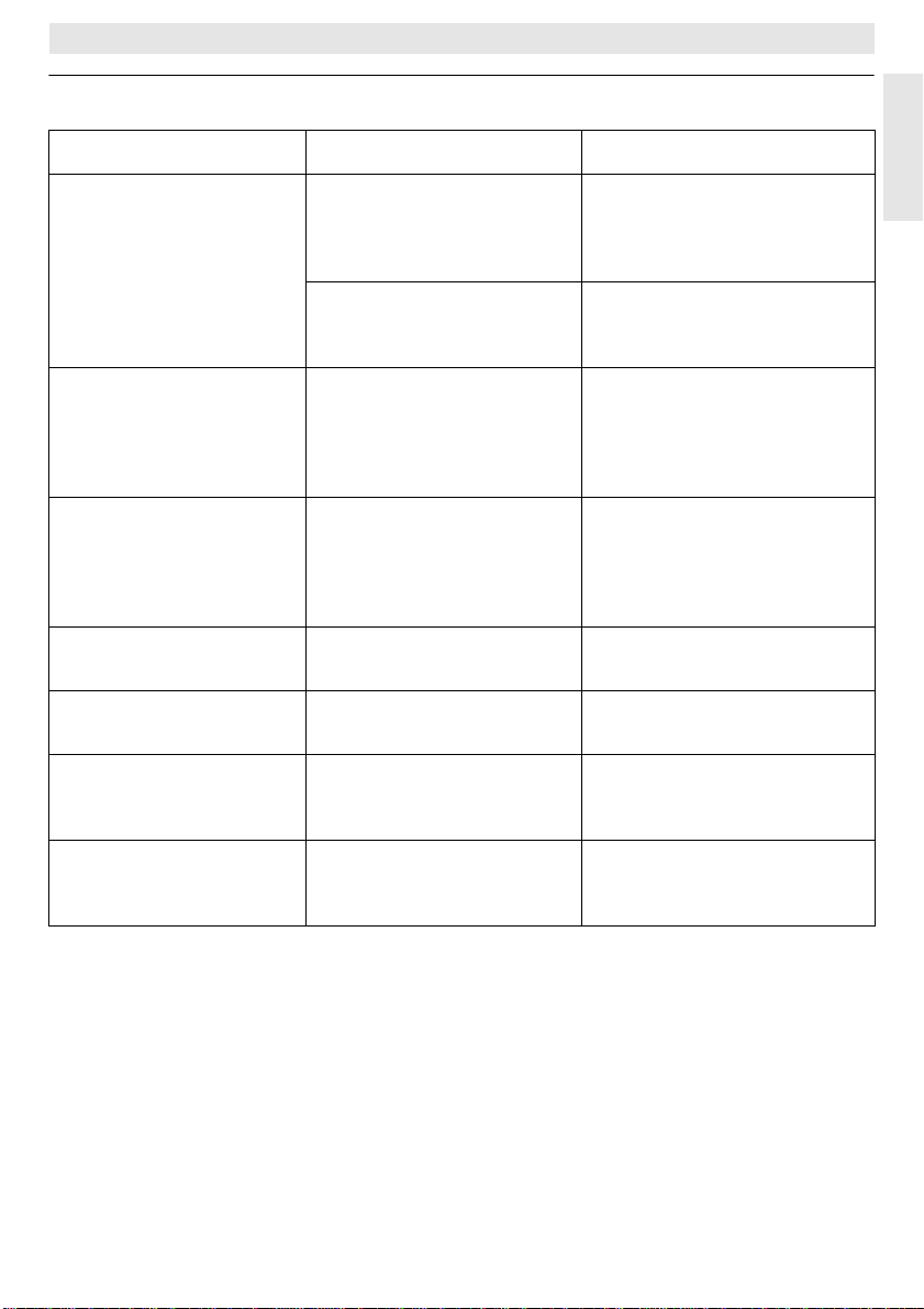
9 Fehlersuche
Beanstandung Ursache Abhilfe
eingestellte
Raumtemperatur
wird nicht erreicht
eingestellte
Raumtemperatur
wird überschritten
zu große Raumtemperaturschwankungen
Temperaturanstieg statt
Absenkung
Im Sparbetrieb
zu hohe Raumtemperatur
Falsche
oder
keine Regelung
Thermostatventil(e) im
Montageraum des Reglers
installiert
V orlauftemperaturwähler am
Heizgerät zu niedrig
eingestellt
Montageort des
Reglers ungünstig,
z. B. Außenwand,
Fensternähe, Zugluft,
…
zeitweilige Einwirkung von
Fremdwärme auf den Regler, z. B. durch Sonneneinstrahlung, Raumbeleuchtung, TV, Kamin, usw.
Tageszeit an der Schaltuhr
falsch eingestellt
Hohe Wärmespeicherung
des Gebäudes
Falsche Verdrahtung des
Reglers
Thermostatventil durch Handventil ersetzen lassen
oder
Thermostatventil ganz öffnen.
Vorlauftemperaturwähler
höher einstellen.
besseren Montageort wählen
(siehe Kapitel Montage) oder
externen Raumtemperaturfühler einsetzen (Zubehör)
besseren Montageort wählen
(siehe Kapitel Montage)
oder
externen Raumtemperaturfühler einsetzen (Zubehör)
Einstellung überprüfen
Sparbeginn früher wählen
Verdrahtung entsprechend
Anschlußplan prüfen und ggf.
korrigieren
Deutsch
keine Anzeige
oder
Anzeige reagiert nicht
sehr kurzer Stromausfall Hauptschalter des Heizgerätes
aus- und wieder einschalten
15
Page 16
TR 200
1 Safety Instructions
The regulator is to be used only in connection with the listed gas heating units.
The respective circuit diagram must be
observed.
The regulator must under no circumstances be connected to the 230 V
mains.
English
Before installing the regulator, the voltage supply (230 V, 50 Hz) to the heating
unit must be interrupted.
The regulator is not suited for installation in damp rooms.
2 Application
TR 200 is a room temperature regulator with a
digital time switch (weekly programme; three
heating and one reduction starting times per
day) for controlling the gas heating units with
continuous control listed below.
Heating unit Mains
ZE/ZWE .. - 2 K...
ZE/ZWE .. - 2 A...
ZR/ZWR/ZSR...-3
ZR/ZWR/ZSR...-4
Heating equipment
with
Bosch Heatronic Illust. yes
connection
Illustr.
Illustr.
Illustr.
Illustr.
TR 200 is in accordance with the regulations
and is recommended for floor-areas up to approx. 80 m
2
.
Room temperature regulators like TR 200 are
not suited for buildings with underfloor heating
systems. In those buildings we recommend
the use of a regulator controlled by atmospheric conditions.
2.1 Scope of delivery
TR 200 includes the room temperature regulator with inserted brief operating instructions
(illustration ).
2
9
10
10
10
11
Malfunction remote
indicator
active
no
no
no
no
2.2 Accessory
An external room temperature sensor RF 1 in
addition to TR 200 is available as accessory.
For example, the use of this temperature sensor is of advantage when the mounting location of the regulator is not suited for measurement of temperature (see chapter 4).
Furthermore, a remote control switch (e.g. a
telephone commander) can be connected by
customers (see chapter 6.8).
The remote control switch must be equipped
with a potential-free contact which is suited for
5 V DC.
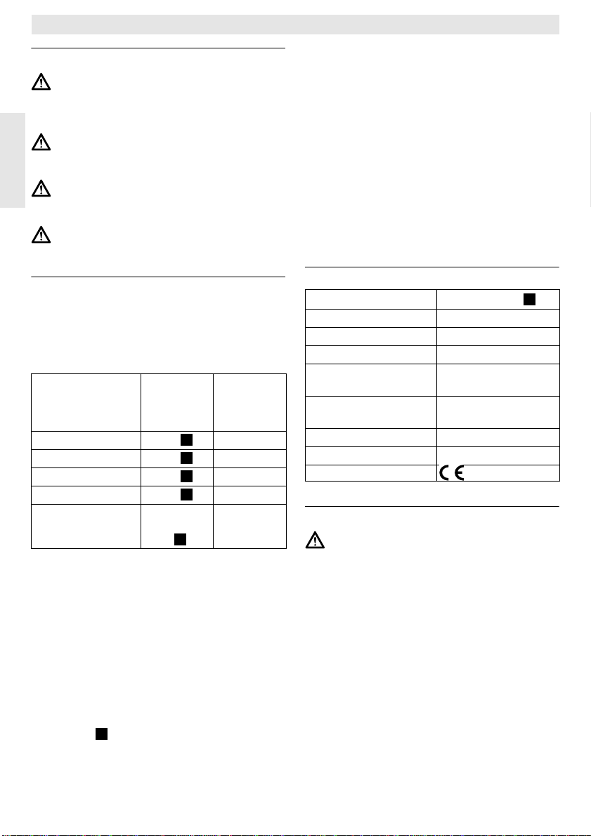
3 Technical Data
Dimensions
see illustration
Rated voltage 24 V DC
Rated current 0.03 A
Regulating range 5 to 30 °C
Regulator
output
constant, 2.8 to
21.5 V DC
Permissible ambient
temperature 0 to +40 °C
Operating reserve approx. 2 hrs.
Protection class IP 20
3
4 Mounting
Before mounting the regulator, the voltage supply (230 V, 50 Hz) to the heating
unit must be interrupted.
4.1 Selecting the mounting location
It is important for the regulation quality of
TR 200 to select a suitable mounting location.
The installation room must be suitable for the
temperature regulation of the complete heating system. The radiators installed in those
rooms must not be equipped with thermostatic
valves. Instead, hand valves with pre-adjustment should be installed so that the heating
output of the radiators in the installation room
of TR 200 can be set to the lowest possible
value.
16
Page 17
TR 200
For the mounting location, select an interior
wall if possible and take care that neither
draughts nor heat radiation (not from behind
the wall, either, e.g. through ducts or hollow
walls, etc.) can have effects on the regulator.
Adequate space must be provided above and
below the regulator so that the room air can
circulate unimpeded through the ventilation
openings (hatched area in illustration ).
4
If the above mentioned conditions cannot all
be met it is recommended to use the external
room temperature sensor RF 1 (accessory)
and to mount this on a more adequate location.
When connecting the room temperature sensor RF 1 the built-in sensor in the regulator is
automatically deactivated.
4.2 Mounting the regulator
• Loosen the top (a) from the base (b) depress the fasteners on the sides (b1) oft the
base and pull off the top (a) (illustration ).
5
• The base (b) can be mounted either
– with two screws (c) to a standard flush
connection box (d) dia. 55 mm
or
– with 4 dowels (6 mm) and tallow-drop
screws (dia. 3,5 mm) directly to the wall
(illustration );
6
Take care that the regulator is mounted in
the right position (the clip must be legible)!
• Connect with the mains accordingly (see
chapter 5).
• Fit the regulator top (a).
4.3 Mounting the accessories
The accessories external room temperature
sensor RF 1 and remote control switch (if existing) must be mounted according to the regulations and the respective mounting instructions.
5 Mains Connection
The following conductor cross sections from
TR 200 to the heating unit must be used:
Length up to 20 m 0.75 mm
Length up to 30 m 1.0 mm2 up to 1.5 mm
Length over 30 m 1.5 mm
2
up to 1.5 mm
Considering the regulations, at least cables of
the construction type H05 VV-... must be used
for mains connection.
All 24 V cables (test current) must be laid separated from cables leading 230 V or 400 V so
that no inductive influencing can take place
(minimum distance100 mm).
In case that inductive external influences e.g.
from power current cables, contact wires,
transformer towers, radio and television sets,
amateur radio sets , microwave equipment, or
similar are to be expected the cables leading
test signals must be shielded.
The corresponding electrical connection plan
(illustration
9 11
to ) is be followed.
5.1 Accessory mains connection
Connect the external room temperature sensor RF 1 (if existing) as shown in
7
illustration
.
If required, the cables of RF 1 can be extended with a cable with twisted twin conductors.
This will make sure that the measured values
of the sensor will not be influenced.
Connect the remote control switch (if existing)
as shown in illustration For minimum re-
8
quirements see chapter 2.2 accessories.
When the switching contact of the remote con-
trol switch is deactivated the heating system
will switch to economical operating mode, “F”
is displayed. When the switching contact is
activated the mode of operation set at the regulator is also activated (illustration ).
6 Operation
TR 200 has some operating elements which
are not needed often after installation and initial operation.
Therefore all operating elements which are
not needed often are covered with a lid.
The operating elements visible when the lid is
closed are part of the so-called “1
level”. All other operating elements make up
the so-called “2
nd
operating level” and the “3
operating level” res. “service level” for the expert.
2
All special operating states are indicated by a
2
displayed text or by control lights. This also
2
applies for the malfunction indicator (only for
heating equipment with Bosch Heatronic).
st
English
8
operating
rd
17
Page 18
TR 200
When the lid is closed the time is shown and
the measured room temperature is indicated
(in 0.5 °C steps).
6.1 The “1st operating level”
20°C
15
25
3010
5
The room temperature to which the regulator
English
will keep in standard heating mode is set with
6.1.1 Control knob (k)
the control knob (k) .
The regulator will always regulate the temper-
ature to this value when the respective red
control light (l) is on.
If the control knob (k) is set to “5”, the respective red control light (l) is off. The regulator will then set the temperature to approx.
5°C so that frost protection in this room is
guaranteed. This means that the heating system is switched off when the temperature exceeds 6°C.
6.1.2 The operating conditions
Automatic operating mode
The basic setting of the regulator is automatic operating mode.
Automatic operating mode means automatic
changeover between standard heating operation and economical operation at the times
pre-set with the time switch (e).
During standard heating operation (=“day”),
the regulator regulates the room temperature
to the value set with the control knob (k), the
respective red control light (l) is on.
During economical heating operation
(=“night”), the regulator regulates the room
temperature to the set economic temperature,
the respective red control light (l) is off. (Presetting of economic temperature see
chapter 6.2.1)
Note: Each time the automatic operating
mode is switched off a control light
comes on or a text is displayed.
The operating mode can be
switched back to automatic operation at any time.
Button
“Continuous heating mode” (g)
When this button is depressed (g) continuous heating operation is activated.
The regulator continuously regulates the room
temperature to the value set with the control
knob (k) .
The respective red control light (f) is on.
The respective red control light (l) is also on
(unless the control knob (k) is set to “5”).
The economical operating mode set at the
time switch is ignored.
The operating mode “continuous heating” will
be activated until:
• the button (g) is depressed again; the
regulator will switch back to the automatic
operating mode
or
• the button (h) is depressed again; the reg-
ulator will switch back to economical operating mode.
In both cases the respective red control
light (f) turns off and the regulator will regulate
the room temperature to the set value.
Tip
Depress this button if you exceptionally
☞
go to bed late (e.g. because of a party). Switch
back to automatic operating mode later.
In case of an illness it might be more comfortable to have a higher room temperature (continuous heating operation). In this case, do not
forget to switch the regulator back to the automatic operating mode.
During a winter holiday or during the summer,
a low room temperature for a longer period
can be selected by depressing the button
“continuous heating” and additionally reducing the temperature with the control knob
(k).
Button
“Economical operating mode” (h)
When the button (h) is depressed the economical operating mode is switched on.
The regulator continuously regulates the room
temperature to the value set with the control
knob “economic temperature” (setting the
economic temperature see chapter 6.2.1).
18
Page 19
TR 200
The respective yellow control light (i) is on.
The respective red control light (l) is off.
The standard heating mode set at the time
switch is ignored.
The economical operating mode will be active
until
• midnight (0000 hours)
or
• the button (h) is depressed again;
the regulator is set back to automatic oper-
ating mode
or
• the button (g) is depressed;
the regulator is set to continuous operating
mode.
In all cases the respective yellow control light
(i) will turn off and the regulator will regulate
the temperature to the set values.
Tip
Use this mode if you exceptionally
☞
leave your house (e.g. for shopping) and the
house should not be heated for this time. As
soon as you are back depress the button (h)
again, the regulator is operating in automatic
mode again and will heat according to the set
temperature.
If you leave the house in the evening or if
you would like to go to bed early depress the
button (h). The regulator terminates the eco-
nomical heating mode at midnight and will
switch back to the usual automatic operating
mode the next morning.
6.2 The “2nd operating range”
nd
The “2
operating range” is accessible after
opening the lid.
When the lid is opened the programming
mode is switched on automatically. The display depends on the setting of the control
knob (n).
15°C
10
20
25
5
6.2.1Control knob “economic
30
temperature” (m)
With this control knob (m) the temperature
to which the regulator must regulate in the automatic operating mode when set to “economic”, as well as in “economical operation
mode” (h).
6.2.2 General information on the timer
The time switch makes it possible to automatically switch on the heating system up to three
times a day at a pre-determined time and to
automatically switch it off three times a day a
pre-determined time.
Those times can be determined individually
for each day.
6.2.3Control knob set to
“Setting the clock”
Setting the time
Turn the control knob (n) to .
Note: At initial operation or after a longer
power failure the symbol
Select day +/-
is displayed. In this case set the
present day, then depress the button
(q) .
The display (e) shows:
Set clock +/12:00
The time is set by depressing the buttons “-”
(o) or “+” (p) .
Briefly depressing the button alters the time by
1 minute, when the button is depressed for a
longer period the time runs faster forward or
backward. The seconds are always set to “0”.
As soon as the button is released the clock will
operate normally.
Tip
Times before 1200 hrs. (12 noon) can
☞
be set faster with the “–” button (o).
When no more alterations are necessary
close the lid.
The display (e) shows:
17:53 21.5°C
Setting the day
Turn the control knob (n) to .
When
Set clock +/- is displayed depress the but-
ton (q). The upper line of the display (e)
shows:
Select day +/-
English
19
Page 20
TR 200
The present day is set by depressing the buttons “–” (o) or “+” (p).
If afterwards you wish to set the time, depress
the button (q).
When no more alterations are necessary
close the lid.
6.2.4Control knob set to
English
Setting the heating programme
The time switch makes it possible to automatically switch on the heating system up to three
times a day at a pre-determined time and to
automatically switch it off three times a day a
pre-determined time.
Those times can be determined individually
for each day.
It is also possible to set the same times for
each day.
To make programming more effective it is
useful to fill in the heating times into the table
provided (see chapter 10). The heating programme which is used for most days of the
week (also applicable if the times deviate
slightly) should be filled in for all days in the
first step. The deviating times can later be effortlessly altered.
Turn the control knob (n) to . The display (e)
shows:
“Heating”
Select day +/-
Depress the button “–” (o) or “+” (p). All days
(or the present day) is displayed in the upper
line.
In the setting
and “economic operation” will start at the respective times each day.
If only one day of the week (e.g. Thursday)
was selected, the set programme for this day
always starts at the pre-set time on this day,
i.e. each Thursday both “heating operation”
and “economic operation” will start at the set
times.
One single day can be set by depressing the
buttons “–” (o) or “+” (p).
Between
played.
All days both “heating operation”
Sunday and Monday All days is dis-
20
The heating times can be set for the displayed
day/all days. For this, depress the button
(q).
The display (e) shows:
1. Start heating
6:00
The required first starting time for heating is
set by depressing the button “–” (o) or “+” (p).
Briefly depressing the button alters the starting time by 10 minutes, when the button is depressed for a longer period the time runs faster forward or backward.
When the required starting time is selected
depress the button (q).
Now the respective first starting time for economic operation must be set.
The display (e) shows:
1. Start econom.
22:00
The required first starting time for economic
operation is set by depressing the button
“–” (o) or “+” (p).
Briefly depressing the button alters the starting time for economic operation by 10 minutes, when the button is depressed for a longer period the time runs faster forward or backward.
As soon as the required starting time for economic operation is selected depress the button (q).
The display (e) shows:
2. Start heating
--:--
Note: --:-- means that this starting time was
not programmed, i.e. only one starting time for heating operation and
one for economic operation is programmed at initial operation (factory
pre-setting) or after a longer power
failure.
If required, the second starting time for heating operation can now be set as described
above, in the chapter “setting the first starting
time”.
Page 21
TR 200
For the second starting time for economic operation, as well as for the third starting times
for heating and economic operation (if required), please proceed as before.
In case that certain starting times are not required, depress the button (q) without
making any alterations.
If a displayed starting time is to be cancelled,
briefly depress the cancel button C (r) with the
tip of a pen. The display shows
When the required starting times are programmed depress the button (q).
The display shows
day as described above and enter the respective times.
Note: If the programme for one single day
Tip
☞
do not have to be entered in chronological se-
was altered after having programmed all days of the week, the
display shows
times when the programme
“All days” is recalled. If one starting
time is now altered for all days of the
week, the original programme for
the various days is deleted and
must be re-programmed as described above.
The various starting times for one day
quence. In the mode
Select day +/-. Now select a
Select day +/-
--:-- .
--:-- at all starting
the regulator
arranges the starting times independently.
You can check the programmed starting times
by proceeding as described above, but without depressing “–” (o) or “+” (p).
If the heating operation is to exceed mid-
night, the last economic operation is ignored.
Enter this starting time as first starting time for
economic operation on the following day. The
regulator recognises the correct sequence of
the starting times although the first starting
time for heating operation is set to a later hour
than the first starting time for economic operation.
Should there be a day on which no heating operation is required (permanently, e.g. office
which is not busy on Sundays), please enter
the required starting time for economic operation (if necessary, the day before) and cancel
all further starting times up to the time you
wish normal heating operation to commence.
If on one day of the week continuous heat-
ing operation is required, please enter the required starting time for heating operation (if
necessary, the day before) and cancel all further starting times up to the time you wish economic operation to commence.
If you wish to carry out extensive alterations
to the programme, it might be better to start off
with the programme pre-set by the factory.
Proceed as described above to delete all individually set starting times, until the display
shows
Select day +/-. Briefly depress the cancel
button C (r).
After this, the programme pre-set by the facto-
ry reappears (for all days: 1
heating operation 06:00 hrs; 1
for economic operation 22:00 hrs, further
starting times
When no more alterations are necessary
close the lid.
Setting the period of absence
Turn the control knobr (n) to . The display
(e) shows:
--:--).
6.2.5Control knob set to
“Holiday”
st
starting time for
st
starting time
Days absent */O
The number of days absent is set by depressing the buttons “–” (o) or “+” (p).
Briefly depressing the button alters the
number of days absent by 1 day, when the
button is depressed for a longer period the
displayed days run faster.
Note: The present day must be entered as
Example: You would like to leave your house
for a two weeks' holiday. You leave the house
Saturday afternoon. Return is planned for Saturday, two weeks later, and you would like the
house to be heated by then.
a day absent, i.e. the regulator
starts with the holiday programme
immediately. The day of return
should only be entered if no heating
operation is required for that day!
English
21
Page 22
If you enter the number of days absent shortly
before leaving, the number entered must be
“14” (Saturday, Sunday, ... Thursday and Friday, since on the Saturday you return you
want the regulator to switch the heating system on as usual.
After closing the lid, the display (e) shows:
14 days absent
17:53 16.5°C
English
The regulator immediately regulates to the
temperature set with the control knob (m)
The remaining days until you return are always displayed. After the set number of days
(at midnight) the regulator automatically terminates economic operation and returns to automatic operation.
If you would like to carry out further alterations
do not yet close the lid.
Tip
Please note that the temperature set
☞
with the control knob (m) should be harmless to your pets, plants, etc. for the entire
course of your absence.
If you intend to return to your house in the
morning, it might be better to start heating
shortly after midnight instead of waiting for
first heating operation in the morning. In this
case, depress the button (q). after having
set the number of days absent. The display
shows:
erating mode required on return with the button “+” (p) or “–” (o), either to continuous
heating operation or to automatic operating
mode. If you have selected continuous heating operation, the temperature is regulated to
the value set with the control knob (k), beginning at midnight before your return. Do not
forget to depress the button (g) after your
return in order to terminate continuous heating
operation.
In case that the holiday operating mode
should be terminated early, it is possible to
either briefly depress the button (g) twice,
or to set the number of days absent to “0” as
described above.
Continuous heating operation for several days
can also be programmed by setting the
number of days as described above and turning up the economic temperature to the required value with the control knob (m).
“Automatic +/-”
. Now you can set the op-
TR 200
6.2.6Control knob set to i
Having the set values displayed
Turn the control knob (n) to the position i. The
upper display line (e) shows the present day.
If the button (q) is depressed, the following group is displayed. Each value in the
group (if entered) is displayed for 5 seconds
before the regulator moves to the next value.
If you wish to have the next value displayed
faster, depress the button (p).
If you wish to have the value displayed for a
longer time, briefly depress the button “–” (o)
and the display keeps showing this parameter.
By depressing the button (q) the display
moves to the next parameter after 5 seconds.
In the first group, the following general values are dis-played (e) in a five-second-time,
non-existing values are not considered:
Display example
(5-second-time
sequence)
Temperatures
Room temp. here
21.5 °C
Room temp. remote
21.0 °C
Room temp. set
21.5 °C
Parameter description
Title of the first group
Measured room tempera-
ture at the regulator “here”
is only displayed if an external sensor (accessory) is
connected.
Measured room temperature at the
external sensor (accessory).
The set temperature with
which the regulator is operating.
22
Page 23
TR 200
In the second group the values of the heating programme are displayed in a five-sec-
ond-time, values which were not entered are
not considered::
Display example
(5-second-time
sequence)
Heating program
Thursday
1. Start heating
6:00
1. Start econom.
9:00
2. Start heating
11:30
2. Start econom.
13:00
3. Start heating
17:30
3. Start econom.
22:00
Friday
Parameter description
Title of the 2nd group
Heating programme for this
day (or All days)
Set 1st starting time for heat-
ing operation for the day
Set 1st starting time for eco-
nomic operation for the day
Set 2nd starting time for heat-
ing operation for the day
Set 2nd starting time for eco-
nomic operation for the day
Set 3rd starting time for heat-
ing operation for the day
Set 3rd starting time for eco-
nomic operation for the day
Heating programme for the
next day etc.
After this the automatic display starts from the
beginning and continues until the control
knob (n) is turned to another position or the lid
is closed.
Setting the language
Turn the control knob (n) to the position i.
Depress the button “–” (o) and keep it de-
pressed until the following is displayed:
Sprache +/-
Set the required language with the button
“+” (p) or “–” (o).
Available languages:
• German/Deutsch • T urkish/Türkce
• English • Polish/P o polsku
• Dutch/Nederlands • Czech/Cesky
• Spanish/Espanol • Slov ak/Slov ensky
• Italian/Italiano • Hungarian/Magyar
• French/FRANCAIS • Slovenian/Slov ensk o
• Portuguese/Portugues • Croatian/Hrv atski
• Danish/Dansk • Lettish/Latviski
• Greek/ELLINIKA • Romanian/Romaneste
When no more alterations are necessary
close the lid.
6.3 The “3
rd
operating level”or
“service level”
(Only for experts)
rd
The “3
operating level” or “service level” for
the expert becomes accessible when the control knob (n) is set to the position and the
button (q) is depressed for longer than 5
seconds. Non-existing values are left out.
Display
example
Room sensor +/–
21.3 °C
Rem. sensor +/–
21.4 °C
Econom. temp.+/–
14.6 °C
Heating temp.+/–
19.7 °C
Parameter
description
Calibrating the built-in
sensor
Calibrating the external sensor (accessory)
Calibrating the displayed value to scale
setting
Control knob (m)
Calibrating the dis-
played value to scale
setting
Control knob (k)
Setting
The displayed
value can
be altered
with the button “–” (o)
or “+” (p) in
steps of
0.1 K by
max. ±3 K
With the button (q) the next parameter is
displayed. If the button is depressed again
when
“Heating temp. +/–” is displayed the “serv-
ice level” is left.
Note: It is important to know that the sen-
sors must not be influenced by external heating sources (body heat)
before calibration. As soon as the
lid is opened the measured values
of the sensors are recorded for calibration.
English
23
Page 24
TR 200
In order to cancel a calibration, the cancel button C (r) must be briefly depressed in the
“service level” when the respective value is
displayed. Now the original value is reactivated.
When no more alterations are necessary
close the lid.
6.4 Operating reserve
The time switch has an operating reserve of
English
approx. 2 hours after having been in continuous operation for at least one day. In case of
a power failure the display is no longer functioning. If the power supply returns within the
operating reserve, the display of the time, and
of the starting times for heating and economical operation returns.
Tip
Take care that the power supply is nev-
☞
er interrupted for longer than 2 hours (do not
switch off the heating system in the summer
but select a low temperature at the regulator;
see chapter 6.1.2 tips for continuous heating).
6.5 Setting the summer and the
standard times
Proceed as described in the chapter “setting the time”!
Do not alter the settings “start heating” and
“start economical operation”!
6.6 Brief operating instructions
The brief operating instructions where all important functions are briefly described are in
the compartment at the right side of the base
(illustration ).
6.7 Regulator with connected room tem-
If a room temperature sensor RF 1 is connected the built-in sensor in the regulator is ineffective. Now the temperature conditions surrounding the external room temperature sensor are decisive for temperature regulation.
Tip
☞
when the mounting location of the regulator
has unfavourable measuring conditions which
are not applicable for the entire house e.g. insolation, a tiled stove nearby, etc.
2
perature sensor RF 1 (accessory)
Use the room temperature sensor RF1
6.8 Regulator with connected remote
control switch (by customers)
With this remote control switch (not included
in the delivery range) the heating system can
be activated from afar.
The most common application is probably the
use of a telephone commander. With this appliance the heating system can be switched
on via any telephone with aid of a personal
identification code.
Before leaving the house the regulator is set
to the mode required at return (automatic operation mode or continuous heating operation).
Then the switching contact of the remote control switch is deactivated, the regulator is operating in the economical operating mode.
The respective red control light (l) is off.
The display (e) shows:
Remotely locked
17:53 16.5°C
If the switching contact is activated (e.g. by a
coded telephone signal) the regulator operates in the pre-set operating mode.
Tip
It will be warm in the house late at night/
☞
early in the morning if the regulator is set to
the position (continuous heating) (g) before
leaving the house, and the switch is deactivated afterwards. Do not forget to set the regulator back to “automatic operating mode” after
returning to the house.
If the house is left for a longer period you
should consider that it could become a lot
cooler (walls could cool down etc.) and therefore it will take a longer time to heat up. Do
switch the heating system on in time.
6.9 Reprogramming
If you would like to carry out extensive alterations to the programme it might be better to
set the regulator back to the programme preset by the factory and to re-enter all starting
times.
Turn the control knob (n) to the position until
the display (e) shows
depress the cancel button C (r).
Select day +/– then briefly
24
Page 25
TR 200
If all settings, even the time and the day (and
the display language) are to be deleted together with the starting times, the cancel button C (r) must be depressed for longer than 10
seconds.
7 Regulator Malfunction Message
Malfunction remote indicator
(not available with all heating systems)
For heating equipment with Bosch Heatronic,
a malfunction in the heating equipment is routed to the regulator.
In case of a malfunction of the heating unit
the control light “Heating” (l) indicates.
The display (e) shows:
Check System
17:53 18.0°C
Note: In this case please proceed as stat-
ed in the operating instructions of
the heating unit or contact your local expert for heating systems.
8 General Information
... and hints on saving energy:
When the regulator settings are altered the
regulator reacts with a time lag. Every 20 seconds the processor compares all desired and
actual values and carries out all necessary
corrections with the necessary speed.
The room in which the room temperature regulator is mounted (control room) determines
the temperature for all other rooms.
I.e. the room temperature in the control room
acts as a control input for the entire heating
network.
For this reason all thermostat regulated radiators located in the control room must be
opened completely at all times. Otherwise the
thermostat valves would reduce the heat supply although the regulator constantly requires
more heat (see also chapter 4.1).
If in the adjoining rooms a lower temperature
is wanted or if the radiator should be turned off
completely, the (thermostatic) radiator valves
must be set accordingly.
Since the room where the room temperature
regulator is mounted acts as a control room,
any external heating sources (e.g. insolation,
tiled stove, etc.) can result in insufficient
heating of the remaining rooms (the radiators
stay cold). In order to avoid this the room
temperature sensor RF 1 can be used
according to the notes in chapter 2.2,
chapter 5.1 and chapter 6.7.
When the room temperature is reduced during
the day or during the night a lot of energy can
be saved.
If the room temperature is reduced by 1 K (°C)
this can save up to 5% of energy.
It is not recommended to let the temperature
of daily heated rooms drop below +15°C.
When the room is heated up again the comfortableness is diminished by the walls which
are cooled down. So if one wants a real comfortable room temperature the regulator must
be turned up and so a lot more energy is used
up than is in case of an even heat supply.
If the building has good thermal insulation it is
possible that the set economic temperature is
not reached. But even in this case energy is
saved since the heating system is not activated.
In this case the starting time for economical
operating mode can be set earlier.
Do not let windows stand ajar for airing the
rooms since this would constantly withdraw
heat from the room without improving the air in
the room considerably. Do avoid continuous
airing!
It is better to air the room briefly but properly
(open the windows completely).
Set the temperature regulator to a lower value
during airing.
English
25
Page 26
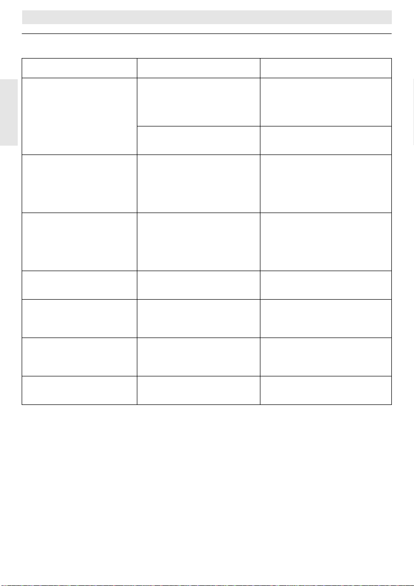
9 Elimination of malfunctions
Malfunction Cause Elimination
TR 200
the set room temperature
is not reached
English
the pre-set room temperature is exceeded
too high variation in room
temperature
rise in temperature
instead of reduction
too high room temperature in economic operating mode
wrong or no regulation wrong wiring of the regulator check the wiring according to
thermostat valve(s) are
installed in the room where
the regulator is mounted
the flow temperature of the
heating unit is set too low
the mounting location of the
regulator is inappropriate,
e.g. outside wall, close to a
window, draught,...
temporary influence of
external heating sources on
the regulator e.g. by insolation, room lighting, TV, fireplace, etc.
the time of day is set incorrectly at the time switch
high regenerative capacity
of the building
have the thermostat valve
replaced by a hand valve or
completely open the thermostat valve(s)
set the flow temperature to a
higher value
select a more appropriate
mounting location (see chapter mounting) or use an external temperature sensor
(accessory)
select a more appropriate
mounting location (see chapter mounting) or use an external temperature sensor
(accessory)
check the setting
select an earlier starting time
for economic operating mode
the circuit diagram and correct
if necessary
no display or the display
does not react
26
very short power failure switch off and on the heating
unit main switch
Page 27
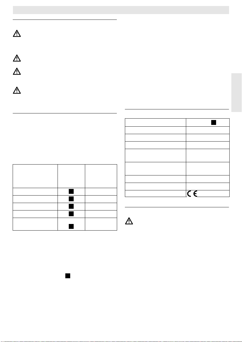
TR 200
1 Instructions de sécurité
Le thermostat ne doit être utilisé que
pour les chaudières à gaz mentionnées
dans ces instructions ; respecter le
schéma électrique correspondant.
Dans aucun cas, le thermostat ne doit
être branché sur le réseau à 230 V.
Avant de brancher le thermostat, l’alimentation (230 V, 50 Hz) de la chaudière doit être interrompue.
Le thermostat n’est pas approprié pour
une installation dans des locaux humides.
2 Utilisation
Le TR 200 est un thermostat d’ambiance à
horloge digitale programmable (programmation hebdomadaire ; trois points différents par
jour pour l’heure de mise en route du chauffage et du mode de service économique) pour le
réglage des chaudières à gaz à réglage continu qui figurent dans le tableau ci-après.
TYP Branche-
ZE/ZWE .. - 2 K...
ZE/ZWE .. - 2 A...
ZR/ZWR/ZSR...-3
ZR/ZWR/ZSR...-4
Chaudières avec
Bosch Heatronic
ment
électr.
Fig.
10
Fig.
10
Fig.
10
Fig.
11
Fig.
Les thermostats d’ambiance du type TR 200
ne sont pas appropriés pour les installations
avec chauffage au sol.
2.1 Éléments fournis avec l’appareil
Le thermostat d’ambiance TR 200 est fourni
avec une notice d’utilisation succincte se trouvant sur le côté (figure ).
2
9
Affichage de
pannes de
chaudière
actif
non
non
non
non
oui
2.2 Accessoires
Le TR 200 peut être utilisé avec le capteur de
température externe RF 1, disponible comme
accessoire. Ce dernier peut être employé par
exemple si le lieu de montage du thermostat
ne convient pas comme endroit pour mesurer
la température (voir chapitre 4).
En plus, sur le lieu de montage, il est possible
de brancher un télérupteur (p. ex. une commande à distance par téléphone) (voir
chapitre 6.8).
Le télérupteur doit disposer d’un contact sans
potentiel approprié pour 5 V DC.
3 Caractéristiques techniques
Dimensions de l’appareil
voir figure
Tension nominale 24 V DC
Courant nominal 0,03 A
Plage de réglage 5…30 °C
Sortie
thermostat
continu,
2,8…21,5 V DC
Plage de température
ambiante admissible 0…+40 °C
Réserve de marche env. 2 heures
Type de protection IP 20
3
4 Montage
Avant de commencer les travaux de
montage, il faut interrompre l’alimentation (230 V, 50 Hz) de la chaudière.
4.1 Choix du lieu de montage
Le choix d’un emplacement approprié est important pour la qualité de réglage du TR 200.
La pièce dans laquelle sera monté le thermostat doit être appropriée pour le réglage de la
température de toute l’installation de chauffage. Les radiateurs de la pièce où est installé le
thermostat d’ambiance ne doivent pas être
munis de robinets thermostatiques. Une solution utilisant de simples robinets préréglés est
recommandée afin que la capacité de réglage
de la puissance des radiateurs au niveau de la
pièce dans laquelle le thermostat TR 200 est
installé puisse être réduite le plus possible.
Français
27
Page 28
TR 200
11
Monter le thermostat si possible sur un mur intérieur et veiller à ce qu’aucun courant d’air ou
flux thermique n’influence le thermostat (même pas de derrière, p. ex. tuyaux vides, murs
creux, etc.).
Il faut qu’il y ait suffisamment de place en dessous et au-dessus du thermostat pour que l’air
ambiant puisse circuler librement à travers les
ouïes de ventilation (voir parties hachurées
sur la figure ).
4
Au cas où les conditions mentionnées ci-dessus ne seraient pas toutes remplies, il est recommandé d’utiliser le capteur de température externe RF 1 (accessoire) et de le monter à
Français
un endroit approprié.
Lorsque le capteur de température externe
RF 1 est branché sur le thermostat, le capteur
de température intégré dans le thermostat
sera automatiquement déconnecté.
4.2 Montage du thermostat
• Détacher la partie supérieure (a) de son socle (b), enfoncer les crochets (b1) placés
sur les côtés du socle et retirer la partie supérieure (a) (figure ).
5
• Le socle (b) peut être fixé soit
– à l’aide de deux vis (c) sur un boîtier de
distribution à encastrer disponible dans
le commerce (d) avec ø 55 mm,
soit
– directement au mur à l’aide de 4 che-
villes (6 mm) et de vis (Ø 3,5 mm)
(figure ) ;
6
aire attention à le placer dans le bon sens
(les marques sur les bornes doivent être lisibles) !
• effectuer le branchement électrique (voir
chapitre 5).
• remonter la partie supérieure du thermostat (a).
4.3 Montage des accessoires
Monter les accessoires, à savoir le capteur de
température externe RF 1 et le télérupteur (s’il
y en a un) conformément aux règlements en
vigueur et aux instructions de montage correspondantes.
5 Branchement électrique
Utiliser la section de conducteur suivante du
TR 200 à l’appareil de chauffage :
Longueur
inférieure à 20 m 0,75 mm
Longueur
inférieure à 30 m 1,0 mm
Longueur
supérieure à 30 m 1,5 mm
Conformément à la réglementation en vigueur, il faut, pour brancher l’appareil, utiliser
des câbles électriques du type H05 VV-... au
minimum.
Tous les câbles de 24 V (courant de mesure)
doivent être posés séparément des câbles de
230 V ou 400 V afin qu’il n’y ait pas d’influence inductive (distance minimale 100 mm).
Lorsqu’il faut s’attendre à des influences inductives extérieures par exemple par câbles à
courant fort, conducteurs aériens, postes de
transformation, postes de radio ou de télévision, stations de radiophonie d’amateurs, appareils à micro-ondes, ou autres, les câbles
qui transmettent les signaux de mesure doivent être blindés.
Respecter le schéma de raccordement électrique correspondant (figure )
5.1 Branchement électrique des
accessoires
Brancher le capteur de température externe
RF 1 (s’il y en a un) conformément à la
7
figure
.
Le cas échéant, il est possible de rallonger les
câbles du RF 1 avec un câble à conducteurs
bifilaires torsadés, assurant ainsi que les valeurs de mesure du capteur ne sont pas influencées.
Brancher le télérupteur (s’il y en a un sur les
lieux) conformément à la figure . Pour les
exigences minimales, voir chapitre 2.2 accessoires.
Lorsque le contact de commutation du télérupteur est fermé, le chauffage se met en
mode de service économique, sur le cadran
est affiché « F ». Lorsque le contact de commutation est ouvert, le chauffage travaille en
mode de service choisi sur le thermostat
(figure ).
8
2
à 1,5 mm
2
à 1,5 mm
.
8
2
2
2
28
Page 29
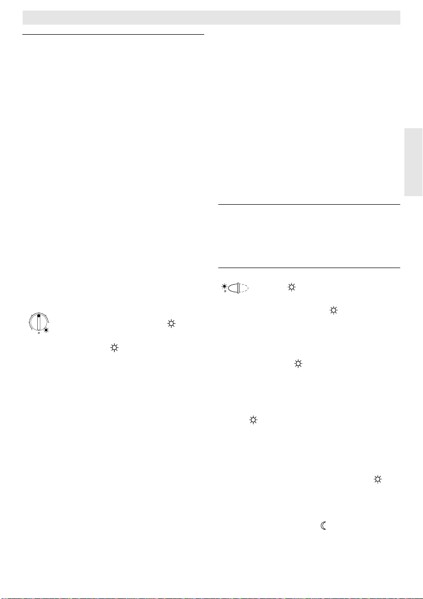
TR 200
6 Utilisation
Le TR 200 dispose de certains éléments de
commande qui, après installation et mise en
service, ne doivent être utilisé que très rarement.
C’est la raison pour laquelle tous les éléments
de commande qui ne sont que très rarement
utilisés sont recouverts d’un capot.
Lorsque le capot est fermé, les éléments de
commande qui sont toujours visibles appartiennent au « premier niveau d’utilisation » ;
tous les autres constituent le « niveau d’utilisation secondaire » et « troisième niveau
d’utilisation » ou « niveau des travaux d’entretien » pour le spécialiste.
Tous les états de service spéciaux sont affichés par un texte sur le cadran ou par des
voyants de contrôle, l’affichage de pannes
également (seulement pour les chaudières
avec Bosch Heatronic).
Lorsque le capot est fermé, l’heure actuelle et
la température ambiante mesurée sont affichées (par pas de 0,5 °C).
6.1 Le « premier niveau d’utilisation »
20°C
15
25
3010
5
Le bouton de réglage (k) permet de choisir
la température ambiante que le thermostat
doit régler en mode de service normal.
Au moment où le voyant de contrôle rouge
correspondant (l) est allumé, le thermostat rè-
gle cette température choisie.
Si le bouton de réglage (k) est positionné sur
« 5 », le voyant de contrôle correspondant
n’est pas allumé.
Le thermostat réglera alors une température
de 5 °C environ et assurera un service horsgel dans la pièce, c’est-à-dire que le chauffage sera éteint lorsque la température est supérieure à 6 °C.
6.1.2 Les modes de service
Service automatique
Le mode de service automatique constitue le
réglage de base du thermostat.
6.1.1 Bouton de réglage (k)
Le mode de service automatique assure le
changement automatique entre le mode de
service normal et le mode de service économique aux heures prédéterminées par
l’horloge (e).
En mode de service normal (=« jour »), le thermostat règle la température sélectionnée au
moyen du bouton de réglage (k) , le voyant de
contrôle rouge correspondant (l) reste constamment allumé.
En mode de service économique (=« nuit »),
le thermostat règle la température économique choisie, le voyant de contrôle rouge correspondant (l) n’est pas allumé. (Pour le réglage de la température économique, voir
chapitre 6.2.1)
Nota: Chaque fois qu’on n’utilise plus le
mode de service automatique, un
voyant de contrôle ou un texte indique
ce changement.
Il est possible à chaque moment de revenir au mode de service automatique.
Touche
« chauffage permanent » (g)
En appuyant sur la touche (g), on met en
marche le mode de service « chauffage permanent ».
Le thermostat règle constamment la température en fonction de la valeur déterminée sur le
bouton de réglage (k).
Le voyant de contrôle rouge correspondant (f)
est allumé.
De plus, le voyant de contrôle rouge
correspondant (l) est allumé (sauf si le bouton de
réglage (k) se trouve en position « 5 »).
Le mode de service économique sélectionné
sur l’horloge n’a aucune influence.
Le mode de service « chauffage permanent »
restera en fonction jusqu’à ce que :
• on appuie de nouveau sur la touche (g)
à ce moment-là, le mode de service automatique sera remis en fonction
ou
• on appuie sur la touche (h) ; à ce moment-
là, le mode de service économique sera mis
en fonction.
Français
29
Page 30
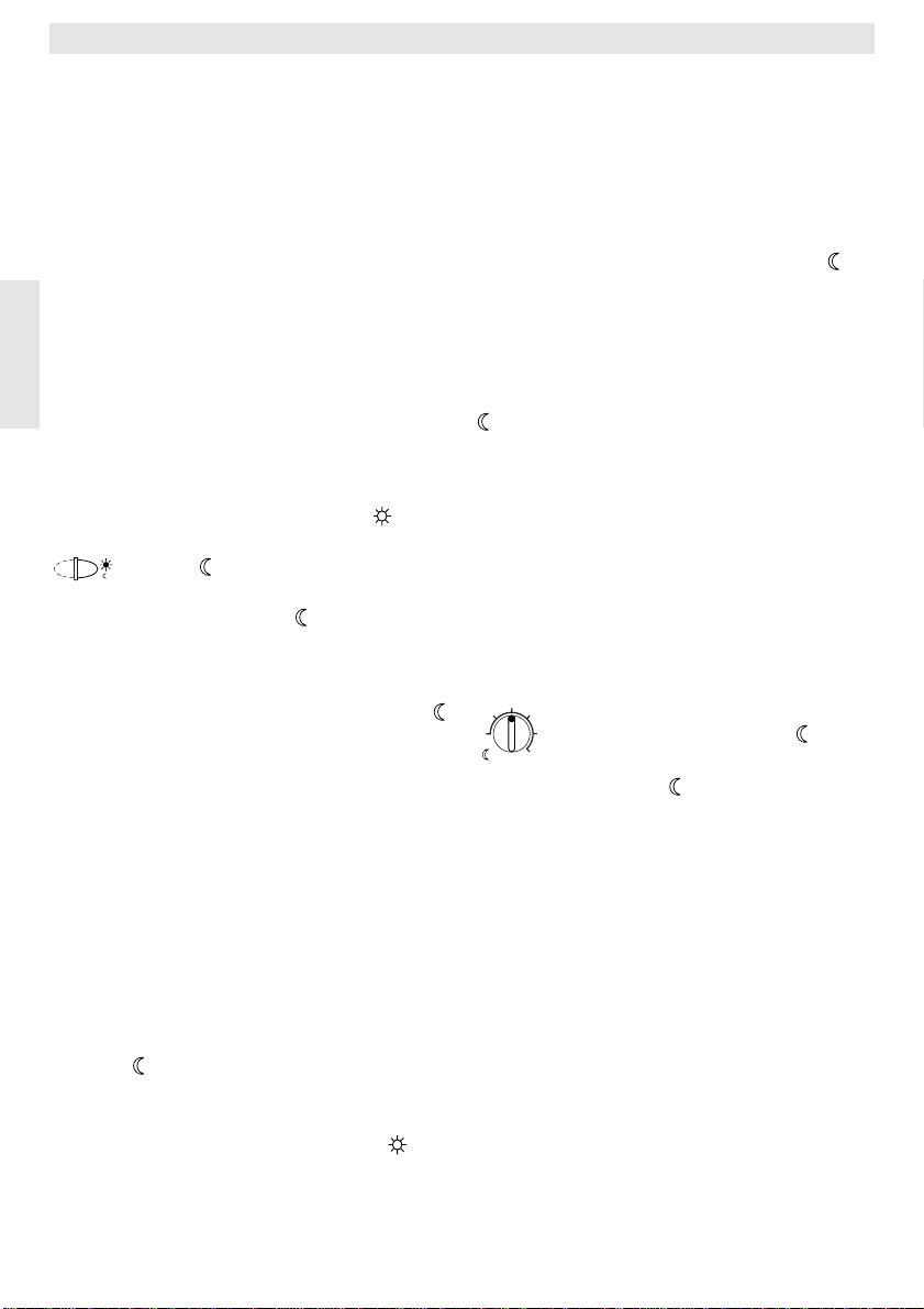
TR 200
Dans les deux cas, le voyant de contrôle rouge correspondant s’éteint (f) et le thermostat
réglera alors la température en fonction de la
température sélectionnée.
Tip
Appuyer sur cette touche lorsque, ex-
☞
ceptionnellement, on va se coucher plus tard
(en raison d’une soirée longue, par exemple).
Ne pas oublier plus tard de remettre sur mode
de service automatique.
En cas d’une maladie, il peut être agréable de
disposer d’un mode de service de chauffage
permanent. Cependant, ne pas oublier plus
tard de remettre sur mode de service automatique.
Français
Pendant les vacances d’hiver ou en été, il est
possible de choisir, pour une période assez
longue, une température de chauffage réduite
; pour ceci appuyer sur la touche « chauffage
permanent » et, en plus, abaisser la température au moyen du bouton de réglage (k).
Touche
« service économique » (h)
En appuyant sur la touche (h), on met en
marche le mode de service économique.
Le thermostat règle constamment la température en fonction de la température « économique » déterminée sur le bouton de réglage
(réglage de la température économique, voir
chapitre 6.2.1).
Le voyant de contrôle jaune correspondant (i)
est allumé.
Le voyant de contrôle rouge correspondant (l)
est éteint.
Le mode de service de chauffage normal réglé sur l’horloge n’a aucune influence.
Le mode de service « économique » restera
en fonction
• jusqu’à minuit (00.00 heure)
ou
• jusqu’à ce qu’on appuie de nouveau sur la
touche (h), à ce moment-là, le mode de
service automatique sera remis en fonction
ou
• jusqu’à ce qu’on appuie sur la touche (g),
à ce moment-là, le mode de service de
chauffage permanent sera mis en fonction.
Dans tous les cas, le voyant de contrôle jaune
correspondant s’éteint (i) et le thermostat réglera alors la température en fonction de la
température sélectionnée.
Tip
Choisissez cette fonction lorsque, excep-
☞
tionnellement, vous quittez l’appartement (p.
ex. pour faire des courses) et que l’appartement
ne doit plus être chauffé. Dès que vous êtes de
retour, appuyez de nouveau sur la touche (h),
le thermostat recommencera à travailler en mode
de service automatique et réglera alors la température en fonction de la température sélectionnée.
Si vous quittez l’appartement le soir ou que
vous alliez très tôt au lit, appuyez sur la touche
(h). Le thermostat arrête le mode de service
économique à minuit et reprend le mode de service automatique le lendemain matin comme
d’habitude.
6.2 Le « niveau d’utilisation secondaire »
Le « niveau d’utilisation secondaire » sera accessible après l’ouverture du capot.
Avec l’ouverture du capot, l’appareil se met
automatiquement en mode de programmation. L’affichage dépend de la position du bouton de réglage (n).
15°C
10
20
25
5
Le bouton de réglage (m) permet de choisir
la température ambiante que le thermostat
doit régler en mode de service automatique
en fonction « économiser » et en « mode de
service économique » (h).
6.2.2 Horloge - Généralités
L’horloge permet de mettre le chauffage automatiquement en marche jusqu’à trois fois par
jour à une heure précise, et d’arrêter automatiquement le chauffage jusqu’à trois fois par
jour à une heure précise.
Ces heures peuvent être fixées différemment
pour chaque jour.
6.2.1 Bouton de réglage « tem-
30
pérature économique » (m)
30
Page 31

TR 200
6.2.3Mettre le bouton de réglage
en position
« Mettre à l’heure »
Mettre à l’heure
Mettre le bouton de réglage (n) en position .
Nota: Lors de la mise en service ou en cas
d’une panne de courant de durée assez longue, c’est
affiché sur le cadran. Dans ce cas-la,
régler le jour actuel, puis appuyer sur
la touche (q).
Sur le cadran (e) apparaît l’affichage suivant :
SELEC. JOUR +/- qui est
REGL. HEURE +/12:00
Appuyer sur les touches « - » (o) ou « + » (p)
pour mettre à l’heure.
Appuyer brièvement sur la touche pour faire
avancer ou reculer l’heure d’une minute, appuyer plus longtemps pour faire avancer ou
reculer l’affichage plus rapidement.
Les secondes sont mises à chaque fois sur
« 0 ». Dès que la touche est relâchée, l’horloge se remet en route « normalement ».
Tip
Pour afficher les heures avant 12.00
☞
(midi), il est plus commode d’appuyer sur la
touche « – » (o).
Refermer le capot lorsqu’il n’y a plus de modifications à effectuer.
Sur le cadran (e) apparaît l’affichage suivant :
17:53 21.5°C
Réglage du jour de la semaine
Mettre le bouton de réglage(n) en position .
Si
REGL. HEURE +/- est affiché sur le cadran, ap-
puyer sur la touche (q) . Dans la ligne supérieure (e) apparaît l’affichage suivant :
SELEC. JOUR +/-
Le jour actuel de la semaine est réglé en appuyant sur les touches « – » (o) ou « + » (p).
Si, ensuite, il faut mettre à l’heure, appuyer
sur la touche (q).
Refermer le capot lorsqu’il n’y a plus de modifications à effectuer.
6.2.4Bouton de réglage en
position « Chauffage »
Régler la mise en route du programme de
chauffage
L’horloge permet de mettre automatiquement
en marche le chauffage jusqu’à trois fois par
jour à des heures précises, et d’arrêter automatiquement le chauffage jusqu’à trois fois par
jour à des heures précises. Ces heures peuvent être fixées différemment pour chaque jour.
Il est également possible de choisir les mêmes heures pour tous les jours.
Afin d’effectuer la programmation d’une manière commode, il est recommandé d’écrire
les heures de chauffage sur le tableau se trouvant (voir chapitre 10). Dans une première
étape, entrer la programmation de chauffage
valable pour la plupart des jours (même sous
forme légèrement modifiée), comme étant valable pour tous les jours. Ensuite, les différentes heures peuvent être modifiées facilement.
Mettre le bouton de réglage (n) en position .
Sur le cadran (e) apparaît l’affichage suivant :
SELEC. JOUR +/-
Appuyer sur la touche « – » (o) ou « + » (p)
Dans la ligne supérieure est affiché
TOUS JOURS (ou le jour actuel de la semaine).
Avec le réglage
mise en route du mode de service « chauffage
» et de la mise en route du mode de service «
économique » sont les mêmes pour tous les
jours de la semaine.
Lorsqu’on a choisi un jour spécial (p. ex. jeudi), c’est toujours ce jour-là et à l’heure sélectionnée, que le programme correspondant se
met en route, c’est-à-dire que tous les jeudis,
le service « chauffage » et le service « économique» se mettent en route aux mêmes heures.
Pour choisir un jour spécifique, appuyer sur
les touches « – » (o) ou « + » (p).
TOUS JOURS est affiché entre DIMANCHE et
LUNDI.
Régler les heures de mise en route du mode
de service chauffage pour le jour de la semaine affiché / pour tous jours en appuyant sur la
touche (q).
TOUS JOURS, les heures de la
31
Français
Page 32

TR 200
Sur le cadran (e) apparaît l’affichage suivant :
1. SERVICE CHAUF
6:00
La première mise en service désirée du mode
de service chauffage est réglée en appuyant
sur les touches « – » (o) ou « + » (p).
Appuyer brièvement sur la touche pour faire
avancer ou reculer de 10 minutes l’heure de la
mise en route du service chauffage, appuyer
plus longtemps pour faire avancer ou reculer
l’affichage plus rapidement.
Lorsque l’heure désirée est mise, appuyer sur
Français
la touche (q).
Maintenant, il faut régler l’heure de la mise en
route du premier service économique correspondant.
Sur le cadran (e) apparaît l’affichage suivant :
1. SERVICE ECONOM.
22:00
Régler la première mise en route du service
économique en appuyant sur la touche
« – » (o) ou « + » (p) eingestellt.
Appuyer brièvement sur la touche pour faire
avancer ou reculer de 10 minutes l’heure de la
mise en route du service économique, appuyer plus longtemps pour faire avancer ou
reculer l’affichage plus rapidement.
Lorsque l’heure désirée est mise, appuyer sur
la touche (q).
Sur le cadran (e)apparaît l’affichage suivant :
2. SERVICE CHAUF
--:--
Nota: --:-- signifie que ce point de commuta-
tion n’est pas affecté, c’est-à-dire que
lors du réglage à l’usine ou après une
panne de courant de durée assez longue, l’appareil n’est réglé que sur une
seule heure pour la mise en route du
mode de service chauffage et une pour
la mise en route du mode de service
économique.
Maintenant, il est possible, si on le souhaite,
de régler l’heure de la deuxième mise en route
du mode de service chauffage de la même façon que lors du réglage de la première mise
en route du service chauffage.
Procéder de la même façon pour la deuxième
mise en route du service économique ainsi
que, si on le souhaite, pour la troisième mise
en route du mode de service chauffage et service économique.
Si l’on n’a pas besoin de certains points de
commutation, appuyer sur la touche (q)
sans pour autant modifier quelque chose.
Si l’on désire effacer un point de commutation
affiché, appuyer brièvement sur la touche
d’effacement C (r) à l’aide d’un crayon. Sur le
cadran est affiché
Lorsque les heures souhaitées sont réglées,
appuyer sur la touche (q).
Sur le cadran est affiché
lectionner alors, comme décrit ci-dessus, un
jour / un autre jour et entrer les heures correspondantes.
Nota: Si, après la programmation de tous les
jours de la semaine, un seul jour a été
modifié, le cadran affiche pour tous les
points de commutation
vel appel du point de programmation
TOUS JOURS. Si, ensuite, un point de
commutation est modifié pour tous les
jours de la semaine, la programmation
initiale de chaque jour de la semaine
est effacée et doit être programmée à
nouveau conformément à la description ci-dessus.
Tip
Il n’est pas nécessaire d’entrer les
☞
points de commutation d’un jour dans l’ordre
--:-- .
SELEC. JOUR +/-. Sé-
--:-- après nou-
chronologique. Le thermostat effectue automatiquement le tri des points de commutation
durant l’affichage
SELEC. JOUR +/-
.
Il est possible de faire afficher les points de
commutation réglés en procédant de la manière décrite ci-dessus sans pour autant appuyer sur les touches « – » (o) « + » (p).
S’il faut chauffer après minuit, la dernière mise
en route du service économique doit être entrée, pour le lendemain, en tant que première
mise en route du service économique. Le
thermostat reconnaît l’ordre des points de
commutation, même si la première mise en
32
Page 33

TR 200
route du service chauffage a lieu après la première mise en route du service économique.
Si, un jour de la semaine, il n’est pas nécessaire de chauffer (p. ex. dans un bureau, dans
lequel on ne travaille pas le dimanche), entrer
le point de commutation correspondant pour
la mise en route du service économique (le
cas échéant, la veille) et effacer tous les
autres points de commutation jusqu’au moment de la remise en route du service chauffage.
Si, un jour de la semaine, il est nécessaire
de chauffer de façon permanente, entrer le
point de commutation correspondant pour la
mise en route du service chauffage (le cas
échéant, la veille) et effacer tous les autres
points de commutation jusqu’au moment de la
remise en route du service économique.
S’il faut effectuer de nombreuses modifica-
tions dans la programmation, il est quelquefois plus commode de partir de la programmation effectuée à l’usine.
Afin d’effacer tous les points de commuta-
tion personnels, procéder de la manière décrite ci-dessus jusqu’à ce que sur le cadran
soit affiché
vement sur la touche d’effacement C (r).
C’est alors le réglage effectué à l’usine (Tous
les jours: première mise en route du service
chauffage 06:00 ; première mise en route du
service 22:00, autres points de commutation
--:-- ) qui est appliqué.
Refermer le capot lorsqu’il n’y a plus de modifications à effectuer.
Réglage des jours de congé
Mettre le bouton de réglage (n) en position
. Sur le cadran (e) apparaît l’affichage sui-
vant :
SELEC. JOUR +/-. Appuyer alors briè-
6.2.5Bouton de réglage en
position
« Congé »
JOURS CONGES
0
Entrer le nombre souhaité de jours de congé
en appuyant sur les touches « – » (o) ou
« + » (p).
Appuyer brièvement sur la touche pour faire
avancer ou reculer de 1 jour le nombre de
jours, appuyer plus longtemps pour faire
avancer ou reculer le nombre de jours plus rapidement.
Nota: Compter le jour actuel avec le nombre
de jours de congé, c’est-à-dire que le
thermostat commence aussitôt avec la
programmation de congé. Le jour de
retour ne doit être compté avec le
nombre de jours de congé que si, ce
jour-là, il ne faut pas chauffer !
Exemple : Vous désirez partir en vacances
pour deux semaines et vous quittez votre appartement le samedi après-midi. Le retour est
prévu pour le samedi après-midi dans deux
semaines, et l’appartement doit être chauffé à
ce moment-là.
Si vous entrez les jours de congé juste avant
le départ, le nombre de jours de congé à entrer est «14 » (samedi, dimanche, ...jeudi et
vendredi, car le thermostat devra à nouveau
régler la mise en route du service chauffage le
samedi).
Avec la fermeture du capot, apparaît sur le
cadran l’affichage suivant (e) :
14 JOURS CONGES
17:53 16.5°C
Le thermostat commence à régler, dès maintenant la température choisie sur le bouton de
réglage (m). Le nombre de jours restant est
constamment affiché. Une fois les jours entrés passés (à minuit), le thermostat termine
automatiquement le mode de service économique et retourne au mode de service automatique.
Ne pas fermer le capot s’il faut effectuer
d’autres modifications.
Tip
Faites attention à ce que la température
☞
réglée sur le bouton de réglage (m) ne nuise
pas à vos animaux domestiques, plantes
d’appartement, etc. durant toute la période
de vos vacances.
Lorsque le retour est prévu dans la matinée, il
serait plus pratique de faire mettre en route le
mode de service de chauffage à partir de minuit au lieu d’attendre la première mise en route du service chauffage. Dans ce cas-là,
appuyer sur la touche (q), après avoir en-
33
Français
Page 34

TR 200
tré le nombre de jours de congé. Sur le cadran
est affiché :
AUTOMATIQUE+/-
. Après les jours
de vacances, il est alors possible de régler sur
le mode de service chauffage permanent ou
automatique à l’aide des touches « + » (p) ou
« – » (o) . Au cas où le mode de service chauffage permanent serait choisi, le thermostat
met en route le chauffage après le dernier jour
des vacances à partir de minuit pour atteindre
la température réglée sur le bouton de réglage
(k). Ne pas oublier, lors de votre retour,
d’appuyer sur la touche (g) afin d’arrêter le
mode de service de chauffage permanent.
Pour arrêter le service des jours de congé
avant terme, il est possible soit : d’appuyer
Français
deux fois de suite sur la touche (g), soit de
remettre le nombre de jours sur « 0 » conformément à la description ci-dessus.
Il est également possible de faire chauffer de
façon permanente pendant plusieurs jours, en
entrant le nombre de jours conformément à la
description ci-dessus et en choisissant la température souhaitée pour le mode de service
économique sur le bouton de réglage (m).
6.2.6Bouton de réglage
en position i
Faire afficher les valeurs réglées
Mettre le bouton de réglage (n) en position
« i ». Dans la ligne supérieure (e) apparaît le
jour actuel.
Lorsqu’on appuie sur la touche
(q), le
groupe suivant est affiché. Chaque valeur du
groupe (s’il y en a une) est affichée pendant
5 secondes, puis le thermostat affiche la suivante. Pour faire dérouler les valeurs plus rapidement, appuyer sur la touche « + » (p).
Pour faire afficher les valeurs plus longtemps,
appuyer brièvement sur la touche « – » (o),
l’affichage restera alors sur ce paramètre.
Appuyer sur la touche (q) pour réactiver le
déroulement automatique de l’affichage.
Dans le premier groupe, les valeurs générales suivantes sont affichées (e) à un rythme
de 5 secondes, les valeurs inexistantes sont
sautées :
Exemple d’affichage
(Déroulement à un
rythme de 5 sec.)
Températures Titre du premier groupe
TEMP. AMB. LOCALE
21,5 °C
TEMP. A DISTANCE
21,0 °C
TEMP. DEMANDEE
21,5 °C
Description des
paramètres
Température ambiante
mesurée sur le thermostat
« LOCAL ».
Température ambiante
mesurée sur la sonde à distance (accessoire) ; est seulement affichée lorsqu’une
sonde à distance est branchée.
Température demandée, utilisée par le thermostat.
Dans le deuxième groupe, les valeurs du
programme de chauffage sont affichées à
un rythme de 5 secondes, les valeurs inexistantes sont sautées :
Exemple
d’affichage
(Déroulement à un
rythme de 5 sec.)
POINTS COMMUT. Titre du deuxième groupe
Jeudi Programme de chauffage pour
1. SERVICE CHAUF
6:00
1. SERVICE ECON.
9:00
2. SERVICE CHAUF
11:30
2. SERVICE ECON.
13:00
3. SERVICE CHAUF
17:30
3. SERVICE ECON.
22:00
Vendredi Programme de chauffage pour le
Description des
paramètres
un jour de la semaine (ou tous les
jours de la semaine)
Première mise en route du mode
de service chauffage réglée pour
un jour de la semaine
Première mise en route du mode
de service économique réglée
pour un jour de la semaine
Deuxième mise en route du mode
de service chauffage réglée pour
un jour de la semaine
Deuxième mise en route du mode
de service économique réglée
pour un jour de la semaine
Troisième mise en route du mode
de service chauffage réglée pour
un jour de la semaine
Troisième mise en route du mode
de service économique réglée
pour un jour de la semaine
prochain jour, etc.
34
Page 35

TR 200
Puis, l’affichage automatique recommence à
partir du début, il continue le déroulement jusqu’à ce que le bouton de réglage (n) soit mis
dans une autre position ou que le capot soit
fermé.
Sélectionner la langue
Mettre le bouton de réglage (n) en position i.
Maintenir la touche « – » (o) appuyée jusqu’à
ce que dans l’affichage apparaisse le message suivant :
Sprache +/-
Choisir la langue désirée en appuyant sur les
touches « + » (p) ou « – » (o).
Langues disponibles :
• Allemand/Deutsch • Truc/Türkce
• Anglais/English • Polonais/P o polsku
• Hollandais/Nederlands • Tchèque/Cesky
• Espagnol/Espanol • Slovaque/Slovensky
• Italien/Italiano • Hongrois/Magyar
• FRANÇAIS/FRANCAIS • Slovène/Slov ensk o
• Portugais/Portugues • Croate/Hrv atski
• Danois/Dansk • Letton/Latviski
• Grec/ELLINIKA • Roumain/Romaneste
Refermer le capot lorsqu’il n’y a plus de modifications à effectuer.
6.3 « Troisième niveau d’utilisation » ou
« niveau des travaux d’entretien »
(Seulement pour le spécialiste)
Le « troisième niveau d’utilisation » ou « niveau des travaux d’entretien » prévu pour le
spécialiste est accessible lorsqu’on met le
bouton de réglage (n) en position et que
l’on maintient la touche (q) appuyée pendant plus de 5 secondes. Les valeurs inexistantes sont sautées :
Exemple
d’affichage
Description des
paramètres
Possibilités de
réglage
SONDE AMB. +/–
21,3 °C
SONDE DIST. +/–
21,4 °C
TEMP. ECO. +/–
14,6 °C
TEMP. CHAUF.
+/– 19,7 °C
Ajustage du capteur
de température intégré
Ajustage du capteur
de température
externe (accessoire)
Ajustage de la valeur
affichée par rapport à
la position sur l’échelle
Boutonde
réglage (m)
Ajustage de la valeur
affichée par rapport à
la position sur l’échelle
Bouton de
réglage (k)
A l’aide des
touches
« – » (o) ou
« + » (p), il
est possible
de modifier
la valeur affichée de
±3 K au
maximum
par pas de
0,1 K
Pour atteindre le prochain affichage, appuyer
sur la touche (q). Si la touche est appuyée encore une fois alors que l’affichage se
trouve sur
TEMP. CHAUF. +/–, on quitte le « ni-
veau des travaux d’entretien ».
Nota: Faire attention à ce que, avant d’effec-
tuer l’ajustage, les capteurs de température ne soient pas influencés par une
chaleur étrangère (chaleur du corps).
Dès que le capot est ouvert, les valeurs de mesure des capteurs sont déterminées pour l’ajustage.
Afin d’effacer un ajustage, appuyer sur la touche d’effacement C (r) dans le « niveau des
travaux d’entretien » lorsque l’affichage correspondant apparaît ; la valeur initiale sera
alors réactivée.
Refermer le capot lorsqu’il n’y a plus de modifications à effectuer.
6.4 Réserve de marche
Après avoir été alimenté par le courant électrique pendant au moins 1 jour, l’horloge dispose d’une réserve de marche de 2 heures environ. Durant une panne de courant, l’affichage
s’éteint. Lorsque l’alimentation en courant redémarre au plus tard dans les 2 heures, l’affichage de l’heure ainsi que les heures de la
mise en route du chauffage et du mode de
service économique sont à nouveau visibles.
Français
35
Page 36

TR 200
Tip
Faire attention à ce que l’alimentation
en courant ne soit jamais interrompue pendant plus de 2 heures (ne pas arrêter le chauffage en été, mais choisir une température
basse sur le thermostat ; voir chapitre 6.1.2
Conseils pour le chauffage permanent).
6.5 Réglage sur heure d’été/
l’heure d’hiver
Procéder comme décrit dans le chapitre
« Mettre à l’heure » !
Ne pas modifier les heures de la mise en route
du chauffage et du mode de service économique !
Français
6.6 Notice d’utilisation succinctes
Dans le compartiment se trouvant sur le côté
droit du socle, il y a une notice d’utilisation
succincte dans laquelle vous trouverez une
courte description des informations les plus
importantes (figure ).
6.7 Capteur de température ambiante
RF 1 (accessoire) branché sur le
thermostat
Lorsque le capteur de température ambiante
RF 1 est branché sur le thermostat, le capteur
de température intégré dans le thermostat est
hors fonction. Dans ce cas-là, c’est la température aux environs du capteur de température ambiante externe qui est prise en considération pour l’affichage de la température ainsi
que pour le réglage de la température.
Tip
Utiliser le capteur de température exter-
☞
ne RF 1 lorsque les conditions de mesure sur
2
le lieu de montage du thermostat ne sont pas
favorables ou qu’elles ne sont pas valables
pour tout l’appartement (p. ex. soleil, poêle en
faïence, etc.)
6.8 Télérupteur (sur les lieux d’installa-
tion) branché sur le thermostat
Grâce à cet interrupteur supplémentaire (qui
ne figure pas dans la gamme de livraison), il
est possible de mettre le chauffage en marche
à distance.
L’application la plus courante est l’utilisation
d’une commande à distance par téléphone.
Celle-ci permet de mettre en route le chauffage à partir de n’importe quel téléphone en
transmettant un code personnel.
Avant de quitter la maison, choisissez le mode
de service sur le thermostat que vous souhaitez avoir au moment de votre retour (service
automatique ou chauffage permanent).
Puis, fermer le contact de télérupteur, le thermostat travaille en mode de service « économique », le voyant de contrôle rouge
« chauffage » (l) est alors éteint.
Sur le cadran (e) apparaît l’affichage suivant :
BLOQUE PAR TEL.
17:53 16:5°C
Lorsque le contact sera ouvert (p. ex. par un
signal téléphonique codé), le thermostat travaille en mode de service choisi préalablement.
L’appartement sera d’une température
Tip
agréable même tard le soir / tôt le matin lorsque, avant de quitter la maison, vous choisissez sur le thermostat le mode de service
(chauffage permanent) (g) et que vous fermez
le contact seulement après. Ne pas oublier
plus tard de remettre sur mode de service
automatique.
Lors d’une absence prolongée, ne pas oublier
que l’appartement (murs, etc.) se refroidit considérablement et qu’il met, en conséquence,
plus longtemps à se réchauffer. Mettre donc le
chauffage à temps.
6.9 Nouvelle programmation
S’il faut effectuer de nombreuses modifications, il est souvent plus commode de remettre le thermostat sur la programmation effectuée à l’usine et d’entrer à nouveau tous les
points de commutation.
Mettre le bouton de réglage (n) sur la position
jusqu’à ce que sur le cadran soit affiché
SELEC. JOUR +/-. Puis appuyer brièvement sur
la touche d’effacement C (r).
Si tous les réglages, même l’heure et le jour de
la semaine (et la langue sélectionnée dans l’affichage) avec les points de commutation doivent être effacés, appuyer sur la touche d’effacement C (r) pendant plus de 10 secondes.
36
Page 37

TR 200
7 Message du thermostat
Affichage de pannes de chaudière (n’existe
pas pour toutes les chaudières)
Dans les chaudières avec Bosch Heatronic,
une panne éventuelle dans la chaudière sera
transmise au thermostat.
En cas de panne, le voyant de contrôle
« chauffage » (l) se met à clignoter.
Sur le cadran (e) apparaît l’affichage suivant :
TESTER INSTALL.
17:53 18.0°C
Nota: Dans ce cas-là, procédez conformé-
ment aux indications se trouvant dans
les instructions de service de votre
chaudière ou consulter un spécialiste.
8 Conseils généraux
... et conseils pour économiser de l’énergie :
Lorsque le réglage du thermostat a été modi-
fié, le thermostat ne réagit qu’après un petit
laps de temps. Le processeur compare toutes
les 20 secondes toutes les valeurs nominales
et réelles et effectue les corrections nécessaires à la vitesse nécessaire.
La pièce (pièce pilote) dans laquelle on a installé le thermostat, détermine la température
des autres pièces.
Cela veut dire que la température ambiante
régnant dans la pièce pilote est considérée
comme étant la température pilote pour toutes
les pièces à chauffer.
Si dans la pièce pilote les radiateurs disposent
de robinets thermostatiques, il faut donc que
ceux-ci soient toujours ouverts. Les robinets
thermostatiques auraient sinon tendance à
brider le chauffage tandis que le thermostat
demanderait toujours plus de chaleur et que la
chaudière fonctionnerait en permanence.
(Voir aussi chapitre 4.1).
Lorsque, dans des pièces voisines, on désire
une température plus basse ou même arrêter
complètement le radiateur, il suffit de régler
les robinets thermostatiques en conséquence.
Étant donné que la pièce dans laquelle est
installé le thermostat d’ambiance agit comme
pièce pilote, il peut en résulter un réchauffement insuffisant des autres pièces (c’est-àdire que le chauffage reste hors fonctionnement) lorsque la pièce pilote est chauffée par
une source de chaleur extérieure (p. ex. soleil, poêle en faïence, etc.). Pour remédier à
ce problème, il est possible d’utiliser le capteur de température ambiante RF 1 comme
accessoire conformément aux indications qui
figurent dans le chapitre 2.2, le chapitre 5.1 et
le chapitre 6.7.
Un abaissement de la température ambiante
diurne ou nocturne permet d’économiser beaucoup d’énergie. L’abaissement de la température ambiante d’un seul degré (°C) peut se traduire par une économie d’énergie pouvant aller
jusqu’à 5%.
Cependant, il n’est pas judicieux de laisser la
température ambiante des pièces chauffées
tous les jours descendre en dessous de
+15 °C. En effet, quand vous remontez le
chauffage, le confort se trouvera amoindri en
raison des murs trop refroidis. Il est vrai que,
pour être sûr d’avoir une température agréable, on a tendance à choisir une température
ambiante trop élevée ce qui se traduit souvent
par une consommation en énergie plus élevée que dans le cas d’un apport de chaleur régulier.
Lorsque le bâtiment dispose d’un bonne isolation thermique, il se peut que la température
économique choisie ne soit pas atteinte.
Pourtant on économise de l’énergie puisque
la chaudière est arrêtée.
Dans ce cas, vous pouvez fixer plus tôt l’heure
de la mise en route du mode de service économique.
Pour aérer les pièces, ne pas laisser les fenêtres en position basculée. Le pièce perd de
manière permanente de la chaleur sans que
l’air s’en trouve amélioré pour autant. Éviter
donc une aération permanente !
Mieux vaut aérer brièvement mais intensément (fenêtres grandes ouvertes).
Régler le thermostat sur une valeur plus basse durant l’aération.
Français
37
Page 38

9 Recherche de pannes
Pannes Causes possibles Remèdes
TR 200
La température ambiante
choisie n’est pas atteinte
Français
La température ambiante
souhaitée est dépassée
Différences de températures ambiantes trop élevées
Montée de la température
au lieu d’abaissement
Robinet(s) thermostatique(s) monté(s) sur les
radiateurs de la pièce où est
installé le thermostat
La température de départ
chauffage réglée sur la
chaudière est trop basse
Emplacement du thermostat mal choisi, p. ex. mur
extérieur, proximité de fenêtres, courant d’air, etc.
Des sources thermiques
extérieures telles que le
soleil, l’éclairage ambiant,
un poste de télévision, une
cheminée, etc. influencent
momentanément le thermostat
Mauvais réglage de l’heure
sur l’horloge
Faire échanger les robinets
thermostatiques contre des
robinets manuels ou ouvrir
complètement les robinets
thermostatiques.
Régler sur la chaudière la
température de départ chauffage sur une position plus
élevée
Choisir un meilleur emplacement pour le thermostat (cf.
chapitre « Montage ») ou utiliser le capteur de température
externe (accessoire)
Choisir un meilleur emplacement pour le thermostat (cf.
chapitre « Montage ») ou utiliser le capteur de température
externe (accessoire)
Contrôler le réglage
Température ambiante
trop élevée en mode de
service économique
Mauvais réglage
ou
pas de réglage du tout
Aucun affichage
ou
l’affichage ne réagit pas
38
Bâtiment dispose d’une
bonne isolation thermique
Mauvais branchement du
thermostat
Panne de courant de très
courte durée
Choisir plus tôt l’heure de la
mise en route du mode de service économique
Contrôler les connexions conformément au schéma électrique et les corriger si nécessaire
Arrêter et remettre en fonction
la chaudière en appuyant sur
l’interrupteur principal de la
chaudière
Page 39

TR 200
1 Instrucciones de seguridad
El regulador debe utilizarse exclusivamente junto con los calefactores de gas
detallados más abajo, debiéndose considerar en cada caso el respectivo esquema de conexión.
En ningún caso debe conectarse el regulador a la red de 230 V.
Antes de instalar el regulador debe interrumpirse la tensión de alimentación
(230 V, 50 Hz) en el calefactor.
El regulador no debe instalarse en recintos con humedad.
2 Utilización
EL TR 200 es un regulador de temperatura
ambiente con reloj digital (programa semanal;
tres puntos de conmutación para calentamiento y tres puntos de conmutación de descenso para cada día de la semana) para los
calefactores a gas de regulación continua detallados a continuación.
TIPO Conexión
eléctr.
ZE/ZWE .. - 2 K... Figura no
ZE/ZWE .. - 2 A... Figura no
ZR/ZWR/ZSR...-3 Figura no
ZR/ZWR/ZSR...-4 Figura no
Calefatores con
Bosch Heatronic Figura si
Se recomienda utilizar el TR 200 para superficies habitables de hasta aprox. 80 m
ejecución es conforme a las prescripciones
legales.
Los reguladores de temperatura TR 200 no
son adecuados para las instalaciones de calefacción por suelo radiante.
Indicador a
distancia de
averías
activo
9
10
10
10
11
2
. Su
2.1 Material que se adjunta
El regulador de temperatura ambiente TR 200
se suministra junto con unas instrucciones
breves de manejo (figura ) que lleva incor-
2
poradas.
2.2 Accesorios especiales
Para el TR 200 puede adquirirse un sensor de
temperatura ambiente RF 1 de instalación externa. Se recomienda su utilización, por ejemplo, si el lugar de montaje del regulador es inadecuado para medir la temperatura (ver
capítulo 4).
Además puede instalarse en la vivienda un
conmutador a distancia (p. ej. para la activación telefónica según capítulo 6.8).
El conmutador a distancia debe disponer de
un contacto, libre de potencial, adecuado
para conmutar 5 V c.c.
3 Datos técnicos
Dimensiones del aparato
según figura
Tensión nominal 24 V DC
Corriente nominal 0,03 A
Margen de regulación 5 a 30 °C
Salida de
regulación
continua;
2,8 a 21,5 V DC
Temperatura ambiente
admisible 0 a +40 °C
Autonomía de
funcionamiento aprox. 2 horas
Tipo de protección IP 20
3
Español
39
Page 40

TR 200
4 Instalación
Antes de montar el regulador debe interrumpirse la tensión de alimentación
(230 V, 50 Hz) en el calefactor.
4.1 Selección del lugar de instalación
Importante para una buena calidad de regulación del TR 200 es la elección de un lugar de
montaje correcto que sea adecuado para regular la temperatura en toda la instalación de
calefacción. Los radiadores allí instalados no
deben estar equipados con válvulas termostáticas. En lugar de ellas deben montarse válvulas manuales preajustables para que sea
mínimo el ajuste de potencia de los radiadores en el lugar de montaje del TR 200.
Seleccione como lugar de montaje en lo posible una pared interior y cuide que no afecten
al regulador ni corrientes de aire ni radiacio-
Español
nes térmicas (tampoco desde la parte trasera
del regulador, p. ej. debido a tuberías en la
pared, conductos en paredes huecas, etc.).
Arriba y debajo del regulador debe haber espacio suficiente para que el aire ambiente
pueda circular libremente por los orificios de
ventilación (área rayada en figura ).
4
Si no pueden cumplirse las condiciones mencionas arriba, se recomienda utilizar un sensor externo RF 1 (accesorio especial) que
puede montarse en un punto más adecuado
para medir la temperatura ambiente.
Al conectar el sensor de temperatura RF 1 se
desconecta automáticamente el sensor que
incorpora el regulador.
4.2 Instalación des regulador
• Soltar la parte superior (a) del zócalo (b)
presionando para ello los enganches laterales (b1) del zócalo y desmontar entonces la
parte superior (a) (figura ).
5
• El zócalo (b) puede montarse opcionalmente
– en una caja empotrada (d) de ø 55 mm,
con dos torni-llos (c) usuales en el comercio,
o
– fijarse directamente sobre la pared con
4 tacos (6 mm) y tornillos (Ø 3,5 mm) de
cabeza de lenteja (figura );
6
Fijarlo en la posición correcta (la inscripción
de los bornes debe ser legible)
40
• Conectarlo eléctricamente de la manera correspondiente (ver capítulo 5).
• Montar la parte superior del regulador (a).
4.3 Instalación de los accesorios
Montar los accesorios especiales como el
sensor de temperatura ambiente RF 1 y el
conmutador a distancia ateniéndose a los
prescripciones legales y a las respectivas instrucciones de instalación.
5 Conexión eléctrica
El cable de unión entre el TR 200 y el calefactor debe tener la sección mínima siguiente:
Longitud
hasta 20 m de 0,75 mm
Longitud
hasta 30 m de 1,0 mm
Longitud
superior a 30 m 1,5 mm
Para realizar las conexiones emplear cable
eléctrico del tipo H05 VV-....
Todos los conductores de 24 V (intensidad de
medición) deben tenderse independientemente de los conductores portadores de
230 V ó 400 V para evitar perturbaciones (separación mínima 100 mm).
Si se prevén efectos perturbadores. p. ej. al
encontrarse cerca cables portadores de alta
intensidad, líneas de toma, estaciones de
transformación, radios y televisores, estaciones de radioaficionados, aparatos de microondas, etc., deben emplearse conductores
apantallados para las señales de medición.
Atenerse al respectivo esquema eléctrico de
conexión (figuras a )
9 11
.
5.1 Conexión eléctrica de los accesorios
Si tiene que utilizar el sensor externo de la
temperatura ambiente RF 1 debe conectarlo
conforme a la figura .
7
En caso de ser necesario puede prolongarse
el RF 1 empleando un cable de hilos gemelos
retorcidos. Con ello se asegura que no se
afectan los valores de medición del sensor.
Si dispone de un conmutador a distancia, éste
debe conectarse según figura . En cuanto a
las propiedades que debe tener, consultar el
capítulo 2.2 accesorios.
8
2
a 1,5 mm
2
a 1,5 mm
2
2
2
Page 41

TR 200
Si el contacto del conmutador a distancia se
encuentra cerrado se conecta la calefacción a
servicio economizado, representándose entonces en la pantalla “F”. Si este contacto
queda abierto, se trabaja entonces en el
modo de operación ajustado previamente en
el regulador (figura ).
8
6 Manejo
Algunos de los elementos de mando del
TR 200 rara vez precisan reajustarse después de realizada la instalación y la puesta en
marcha.
Por ello se mantienen ocultos detrás de una
tapa todos los elementos de mando usados
con poca frecuencia.
Todos los elementos de mando visibles con la
tapa cerrada pertenecen al “1.
nes”. Todos los elementos de mando restantes corresponden al “2.º nivel de funciones” y
al “3er nivel de funciones”, o bien, al “nivel de
servicio” reservado para el técnico.
Todos los modos de operación especiales se
indican como texto en la pantalla o con pilotos, al igual que la indicación de fallo (sólo en
calefactores con Heatronic Bosch).
Si la tapa está cerrada se muestra la hora actual y la temperatura ambiente medida (con
una resolución de 0,5 °C).
6.1 El “1.
20°C
15
5
er
nivel de funciones”
25
3010
6.1.1 Mando giratorio (k)
Con el mando giratorio (k) se ajusta la temperatura ambiente de regulación en el modo
de calentamiento normal.
El regulador trabaja regulando a esa temperatura al encenderse el piloto rojo correspondiente (l).
Si el mando giratorio (k) está colocado en “5”
no se enciende el respectivo piloto rojo (l). El
regulador sostiene entonces 5 °C aprox. para
proteger el recinto contra heladas. O sea, que
la calefacción se mantiene apagada por encima de 6 °C.
er
nivel de funcio-
6.1.2 Los modos de operación
Funcionamiento automático
El ajuste básico del regulador corresponde al
funcionamiento automático.
Éste se encarga del cambio automático entre
el calentamiento normal y el servicio economizado de acuerdo a las horas fijadas en el
reloj de programación (e).
El regulador trabaja en el modo de calentamiento normal (=“día”) regulando la temperatura ajustada en el mando giratorio (k). El respectivo piloto rojo (l) está encendido permanentemente.
El regulador trabaja en el modo de servicio
economizado (=“noche”) regulando a la temperatura con modo economizado, quedándose apagado el respectivo piloto (l) (ajuste de
la temperatura con modo economizado según
capítulo 6.2.1)
Nota: Siempre que se abandone el modo
automático, esto se indica por un piloto o con texto.
Siempre que se quiera puede retornarse al modo de funcionamiento
automático.
Tecla
“calentamiento normal” (g)
Al pulsar la tecla (g) se conecta el modo de
operación normal de calentamiento.
El regulador mantiene constantemente la
temperatura ajustada en el mando giratorio
(k).
El piloto rojo correspondiente (f) se ilumina.
Además se ilumina también el respectivo pilo-
to rojo (l) (a no ser que el mando giratorio
(k) se encuentre en la posición “5”).
Se ignora el modo con servicio economizado
ajustado en el reloj de programación.
El modo de operación “calentamiento normal”
se mantiene hasta que:
• se pulse nuevamente la tecla (g), cambiando entonces al modo de funcionamiento automático,
o
• presionando la tecla (h) para activar el
servicio economizado.
Español
41
Page 42

TR 200
En ambos casos se apaga el piloto rojo (f) y el
regulador trabaja manteniendo la temperatura
de regulación.
Tip
Pulse esta tecla siempre que quiera
☞
mantener caliente la vivienda durante un tiempo más prolongado que el programado. No olvide sin embargo cambiar después al modo
con funcionamiento automático.
Durante las vacaciones de invierno o en verano puede seleccionarse una temperatura de
calentamiento menor durante un tiempo prolongado, presionando para ello la tecla de calentamiento normal y reduciendo
adicionalmente la temperatura en el mando
giratorio (k).
Tecla
“servicio economizado” (h)
Español
Pulsando la tecla (h) se conecta el modo de
operación con servicio economizado.
El regulador mantiene entonces constante la
“temperatura con modo economizado” ajustada en el mando giratorio (ajuste de la temperatura con modo economizado según
capítulo 6.2.1).
El piloto amarillo correspondiente (i) se enciende.
El respectivo piloto rojo (l) está apagado.
Se ignora el calentamiento normal ajustado
en el reloj de programación.
El modo de operación con “servicio economi-
zado” se mantiene hasta
• medianoche (00.00 en el reloj)
o,
• presionar la tecla (h) presionar la tecla
(h) nuevamente, con lo que se ajusta otra
vez el modo de funcionamiento automático,
o,
• presionar la tecla (g), activando así el
modo de calentamiento normal.
En todos los casos se apaga el respectivo piloto amarillo (i) y el regulador trabaja en base
a las temperaturas correspondientes ajustadas.
Tip
Utilice esta modalidad si sale un rato
de su casa y no quiere que la vivienda se siga
calentando. Al regresar a su casa, pulse la tecla (h) para que el regulador trabaje nueva-
mente con funcionamiento automático y
regule conforme a la temperatura ajustada.
Si así lo desea, puede programar que el servicio economizado se desactive por si sólo a
medianoche, presionando la tecla
(h). El regulador cambia a la mañana siguiente al
modo de funcionamiento automático habitual.
6.2 El “2.º nivel de funciones”
Para acceder al “2.º nivel de funciones” debe
abatirse la tapa.
Al abrir la tapa se ajusta automáticamente el
modo de programación. La indicación en la
pantalla depende de la posición en que se encuentre el conmutador giratorio (n).
15°C
10
20
25
5
6.2.1 Mando giratorio
30
“temperatura con modo
economizado” (m)
Con el mando giratorio (m) se ajusta la temperatura ambiente que debe mantener el regulador con funcionamiento automático en los
modos “economizar” y “servicio economizado” (h).
6.2.2 Generalidades sobre el reloj
El reloj de programación permite conectar automáticamente la calefacción a tres horas diferentes del día y desconectarla automáticamente también a otras tres horas diferentes.
Estas horas pueden fijarse individualmente
para cada día.
6.2.3Colocar el conmutador
giratorio en la posición
“Puesta a hora”
Puesta a hora del reloj
Girar el conmutador giratorio (n) a la posición
.
42
Page 43

TR 200
Nota: En la puesta en marcha o después
En la pantalla (e) se muestra:
de un corte del fluido eléctrico prolongado aparece
en este caso el día actual de la semana, y presionar después la tecla
(q) .
Elegir día +/-. Ajustar
Puesta a hora +/12:00
La hora se ajusta presionando las teclas “-”
(o) o “+” (p).
Con cada pulsación breve de las teclas se va
cambiando el tiempo en saltos de un minuto.
Los segundos se ponen cada vez a “0”. Nada
más soltar la tecla se marca el tiempo “normal”.
Tip
Las horas anteriores a las 12.00 (me-
☞
diodía) se ajustan más rápidamente con la “ –”
tecla (o).
Cerrar la tapa, si no se quieren realizar más
modificaciones.
En la pantalla (e) se muestra:
17:53 21.5°C
Ajuste del día de la semana
Girar el conmutador giratorio (n) a la posición
. Al aparecer
cla (q). En la primera línea de la pantalla (e)
se muestra:
Puesta a hora +/- , presionar la te-
Elegir dia +/-
El día de la semana actual se ajusta pulsando
las teclas “–” (o) “+” (p).
Si quiere ajustarse la hora a continuación,
presionar entonces la tecla (q).
Cerrar la tapa si no quiere realizar más modificaciones.
6.2.4Conmutador giratorio en
posición “Calefacción”
Ajuste del programa de calentamiento
El reloj de programación permite ajustar para
cada día hasta tres horas de conexión y otras
tres horas de desconexión automática de la
calefacción.
Estas horas pueden ajustarse individualmente para cada día.
Asimismo es posible ajustar las mismas horas
para Todos los días .
Para poder programar de manera más eficaz
es recomendable registrar las horas de calentamiento en la tabla (ver capítulo 10). El programa de calentamiento más frecuente para
la mayoría de los días (también con ligeras
modificaciones) debe introducirse en el primer paso y asignarse a Todos los días. Las
horas divergentes pueden modificarse después con gran facilidad.
Girar el conmutador giratorio (n) a la posición
. En la pantalla (e) aparece:
Elegir dia +/-
Presionar la tecla “–” (o) o “+” (p). Se representa entonces
mana actual) en la línea superior.
En la posición
riamente a la misma hora el modo de “Calentamiento” y “Economizar”.
En caso de haber seleccionado un día de la
semana concreto (p. ej. jueves), se activa entonces siempre el respectivo programa para
ese día. O sea que se inicia cada jueves a la
misma hora el modo de “Calentamiento” o
bien el modo “Economizar”.
Un día de la semana concreto se selecciona
presionando las teclas “–” (o) o “+” (p).
Entre
Domingo y Lunes se representa Todos los
días.
Para el día de la semana/todos los días mostrado pueden fijarse las horas de calentamiento. Presionar para ello la tecla (q).
En la pantalla (e) aparece:
Todos los días (o el día de la se-
Todos los días se comienza dia-
1. inicio calef.
6:00
La primera hora para inicio de calentamiento
se ajusta presionando las teclas “–” (o) o
“+” (p).
Con cada pulsación de la tecla se varía la
hora de inicio de calentamiento en saltos de
10 minutos, y en caso de mantenerla presionada se varía la hora más rápidamente.
43
Español
Page 44

TR 200
Tras haber ajustado el tiempo deseado, presionar la tecla (q).
Seguidamente debe ajustarse la primera hora
de inicio del servicio economizado.
En la pantalla (e) se aparece:
1. inicio econ.
22:00
La primera hora de inicio del servicio economizado se ajusta presionando las teclas
“–” (o) o “+” (p).
Con cada pulsación de la tecla se varía la
hora de inicio de calentamiento en saltos de
10 minutos, y en caso de mantenerla pulsada
se varía la hora más rápidamente.
Tras haber ajustado la hora deseada presionar la tecla (q) .
Español
En la pantalla (e) se representa:
2. inicio calef.
--:--
Nota: --:-- significa que ese punto de con-
Seguidamente puede introducirse la hora
para el segundo inicio de calentamiento procediendo de manera análoga al inicio de calentamiento descrito previamente.
Para el segundo inicio del servicio economizado, y en caso de desearlo, para los terceros
inicios de calentamiento y del servicio economizado, proceder de manera similar.
De no precisarse algunos puntos de conmutación presionar la tecla (q), cuidando en no
modificar nada.
Si se quiere borrar el punto de conmutación
mostrado, presionar brevemente la tecla de
borrado C (r) con un objeto terminado en punta. En la pantalla aparece entonces --:--.
Una vez ajustados todos los tiempos deseados presionar la tecla (q).
mutación no está ocupado, como
es el caso en el ajuste de fábrica o
después de un corte de fluido eléctrico prolongado, ya que viene ajustada únicamente una hora de inicio
de calentamiento y otra para el servicio economizado.
Se muestra entonces
ces, conforme a la descripción más arriba, un
día individual/diferente e introducir los respectivos tiempos.
Nota: Si después de la programación de
Tip
☞
conmutación de un día en orden cronológico.
Al representarse en la pantalla
regulador ordena automáticamente los puntos de conmutación.
Vd. puede visualizar los puntos de conmutación ajustados procediendo según la manera
descrita más arriba, aunque sin presionar
“–” (o) o “+” (p).
Si quiere continuarse calentando hasta pasa-
da la medianoche, se suprime la última hora
de inicio del servicio economizado. Introducir
ésta al siguiente día como 1er inicio del servicio economizado. El regulador sabe diferenciar la secuencia de los puntos de
conmutación, a pesar de que el 1er inicio de
calentamiento sea posterior al 1er inicio del
servicio economizado.
Si por principio no quiere ponerse la calefacción un día específico de la semana (p. ej. los
domingos, en una oficina), introducir entonces
la respectiva hora de inicio del servicio economizado (si es preciso el día anterior) y borrar
todos los puntos de conmutación restantes
hasta el momento en que deba calentarse
nuevamente.
Si por principio quiere calentarse conti-
nuamente un día específico de la semana introducir entonces la hora de inicio de
calentamiento (si es preciso el día anterior), y
borrar todos los puntos de conmutación restantes hasta el momento que quiera trabajarse con el servicio economizado de nuevo.
todos los días de la semana se modificase un único día, aparece en la
pantalla en todos los puntos de conmutación
nuevamente el punto de programación
entonces un punto de conmutación
para todos los días, se borra entonces el programa previo de los días
individuales de la semana, debiendo programarse de nuevo según la
descripción realizada más arriba.
No es necesario introducir los puntos de
Elegir día +/-. Elegir enton-
--:-- , después de activar
“Todos los días”. Si se modifica
Elegir día +/-
, el
44
Page 45

TR 200
Si tiene que realizar grandes modificaciones en el programa, es posiblemente más efi-
caz tomar como base el programa con los valores ajustados de fábrica.
Para borrar todos los puntos de conmuta-
ción introducidos por Vd. debe proceder de
la forma descrita más arriba hasta representarse en la pantalla
ces brevemente la tecla de borrado C (r).
Con ello se activa nuevamente el ajuste de fábrica (Todos los días : 1er inicio de calentamiento 06:00; 1er inicio del servicio economizado 22:00, demás puntos de conmutación
--:-- ).
Cerrar la tapa si no quiere realizar más modificaciones.
6.2.5Conmutador giratorio en
Ajuste de los días de ausencia
Girar el conmutador giratorio (n) a la posición
. En la pantalla (e) aparece:
Elegir día +/-. Pulse enton-
posición “Ausencia”
Dias ausencia +/0
La cantidad de días de ausencia se ajusta
presionando las teclas “–” (o) o “+” (p).
Con cada pulsación de la tecla se van variando los días de ausencia en saltos de 1 día, y
en caso de mantenerla presionada se modifica rápidamente el número de días.
Nota: El día actual debe contabilizarse
Ejemplo: va estar ausente dos semanas, y
quiere salir un sábado por la tarde de su casa.
Esta previsto que regrese el sábado por la tarde transcurridas las dos semanas, y desea
que ese día su casa esté caliente.
también al determinar los días de
ausencia, o sea, que el regulador
arranca inmediatamente con el programa de ausencia. El día de regreso se contabiliza solamente también, ¡si no va a ponerse la calefacción ese día!
Si introduce los días poco antes de salir de
casa, el número de días de ausencia es entonces “14” (sábado, domingo, ... jueves y
viernes, ya que quiere que el regulador active
la calefacción el sábado).
Al cerrar la tapa aparece en la pantalla (e):
14 dias ausencia
17:53 16.5°C
El regulador trabaja inmediatamente con la
temperatura ajustada en el mando giratorio
(m). La cantidad de días restantes se va mostrando permanentemente. Transcurridos los
días introducidos (a medianoche), el regulador finaliza automáticamente el servicio economizado y retorna al funcionamiento automático.
Si quiere realizar más modificaciones no cierre la tapa todavía.
Tip
Tenga en cuenta que la temperatura
☞
ajustada en el mando giratorio (m) tiene que
ser adecuada para los animales domésti-
cos, plantas, etc. durante toda su ausencia.
Si tiene previsto regresar ya por la mañana,
puede ser conveniente comenzar a calentar a
partir de medianoche en lugar de esperar a la
hora del 1er inicio de calentamiento. En este
caso presione Vd. la tecla (q) tras haber
ajustado los días de ausencia. En la pantalla
aparece:
ajustarse el modo de operación con calentamiento normal o automático con la tecla
“+” (p) o “–” (o) al finalizar los días de ausen-
cia. Si ha seleccionado el calentamiento normal se calienta entonces a la temperatura
ajustada en el mando giratorio
de medianoche, una vez transcurrido el último
día de ausencia. No olvide presionar la tecla
tamiento normal.
Si quiere desactivar el modo de ausencia
antes de tiempo, entonces puede: presionar
la tecla (g) dos veces seguidas, o fijar el
número de días a “0” según la descripción
realizada previamente.
“Automático +/-”.
(g) tras su regreso, para cancelar el calen-
Seguidamente puede
(k) a partir
Español
45
Page 46

TR 200
También puede ajustarse un calentamiento
normal activo durante varios días, fijando el
número de días según la descripción realizada previamente, e incrementando la temperatura al valor deseado para el servicio
economizado en el mando giratorio (m).
6.2.6Conmutador giratorio en
posición i
Representación de los valores ajustados
Girar el conmutador giratorio (n) a la posición
i. En la pantalla superior (e) se representa el
día actual de la semana.
Al presionar la tecla
(q) se muestra el grupo siguiente. Cada valor existente en el respectivo grupo se muestra durante 5 segundos, y después, el regulador pasa al siguiente. Si quiere efectuar una lectura más rápida
Español
puede ir pasando los valores con la tecla “+”
(p).
En caso de querer retener los valores presione la tecla “–” (o), la pantalla muestra entonces continuamente ese parámetro.
Presionando la tecla (q) se activa de nuevo el salto automático al siguiente parámetro.
En el 1er grupo aparecen en la pantalla (e)
los siguientes valores generales en una cadencia de 5 segundos, omitiéndose las posiciones sin valores:
Ejemplo de
indicación
(Secuencia en
cadencia de 5 s)
Temperaturas
Tmp. amb. local
21,5 °C
Tmp. amb. remota
21,0 °C
Tmp. amb consig.
21,5 °C
Descripción de
parámetros
Título del 1er grupo
Temperatura ambiente
medida en el regulador
“local” se indica únicamente si se encuentra
conectado además un
sensor externo (accesorio).
Temperatura ambiente
medida en el sensor
externo (accesorio).
Temperatura de consigna
con la que trabaja el regulador.
En el 2.º grupo se muestran los valores del
programa de calefacción en cadencia de 5 s,
omitiéndose las posiciones sin valores:
Ejemplo de
indicación
(Secuencia en
cadencia de 5 s)
Progr. calentam. Título del 2.º grupo
Jueves Programa de calentamiento
1. inicio calef.
6:00
1. inicio econ.
9:00
2. inicio calef.
11:30
2. inicio econ.
13:00
3. inicio calef.
17:30
3. inicio econ.
22:00
Viernes Programa de calentamiento
Descripción de
parámetros
para un día de la semana (o
Todos los días)
1er inicio de calentamiento
ajustado para el día seleccionado
1er inicio del servicio economizado ajustado para el día seleccionado
2.º inicio de calentamiento ajustado para el día seleccionado
2.º inicio del servicio economizado ajustado para el día seleccionado
3er inicio de calentamiento
ajustado para el día seleccionado
3er inicio del servicio economizado ajustado para el día seleccionado
para el siguiente día de la
semana, etc.
Seguidamente se inicia de nuevo la representación automática en la pantalla, siempre que
no se gire el conmutador giratorio (n) o se cierre la tapa.
Selección del idioma
Girar el conmutador giratorio (n) a la posición i.
Mantener presionada la tecla “–” (o), hasta
obtener la siguiente representación en la pantalla:
Sprache +/-
Seleccionar el idioma deseado con la tecla
“+” (p) o “–” (o).
46
Page 47

TR 200
Idiomas disponibles:
• Alemán/Deutsch • Turco/Türkce
• Inglés/English • Polaco/P o polsku
• Holandés/Nederlands • Checo/Cesky
• Español/Espanol • Eslovaco/Slov ensky
• Italiano/Italiano • Húngaro/Magyar
• Francés/FRANCAIS • Eslo veno/Slo v ensk o
• Portugués/Portugues • Croata/Hrvatski
• Danés/Dansk • Letón/Latviski
• Griego/ELLINIKA • Rumano/Romaneste
Cerrar la tapa si no se quieren realizar más
modificaciones.
6.3 El “3er nivel de funciones” o “nivel
de servicio”
(Sólo para personal técnico)
Al “3er nivel de funciones” o “nivel de servicio”
reservado para el personal técnico, se accede
colocando el conmutador giratorio (n) en la
posición y presionando la tecla (q) durante más de 5 segundos. Se omiten aquellas
posiciones sin valores:
Ejemplo de
indicación
Sens. local +/–
21,3 °C
Sens. remoto +/–
21,4 °C
Temp. econ. +/–
14,6 °C
Temp. calent. +/–
19,7 °C
Descripción
de parámetros
Calibrado del
sensor incorporado
Calibrado del
sensor externo
(accesorio)
Calibrado del
valor indicado
respecto a la
posición en la
escala del
mando giratorio
(m)
Calibrado del
valor indicado
respecto a la
posición en la
escala del
mando giratorio
(k)
Posibilidades de
ajuste
El valor
mostrado
puede
variarse
con las
teclas
“–” (o) o
“+” (p) en
pasos de
0,1° K
hasta máx.
±3 K
Con la tecla (q) puede pasarse a la siguiente representación en la pantalla. En
caso de presionar nuevamente la tecla en
la pantalla
“Temp. calent. +/–” se abandona en-
tonces el “nivel de servicio”.
Nota: Al calibrar los sensores debe cui-
darse que no se vean afectados por
fuentes de calor adicionales (calor
corporal). En el momento de abrir la
tapa se retienen los valores de medición del sensor para el calibrado.
Para cancelar el calibrado debe presionarse
brevemente la tecla de borrado C (r) encontrándose en la respectiva pantalla del “nivel
de servicio”, activándose así el valor anterior.
Cerrar la tapa si no quieren realizarse más
modificaciones.
6.4 Autonomía de funcionamiento
El reloj de programación dispone de autonomía de funcionamiento de aprox. 2 horas si ha
estado funcionando como mínimo un día entero. En caso de un corte del fluido eléctrico
se apaga la pantalla. Al volverse a alimentar
con corriente dentro del plazo de autonomía
de funcionamiento, se conservan en la pantalla la hora, así como los inicios de calentamiento y del servicio economizado.
Tip
Ponga atención en no interrumpir la ali-
☞
mentación de corriente durante un tiempo superior a las 2 horas (en lugar de desconectar
la calefacción en verano, ajuste en el regulador una temperatura menor; ver consejo en
capítulo 6.1.2 sobre el calentamiento normal).
6.5 Ajuste de la hora de verano/invierno
Proceda según el capítulo “Puesta en hora
del reloj”
No modifique las horas de activación del “inicio de calentamiento” y del “inicio de servicio
economizado”!
6.6 Instrucciones breves de manejo
En el compartimiento en el lado derecho del
zócalo se encuentran las instrucciones breves de manejo, que describen de forma somera los pasos más importantes (figura ).
2
Español
47
Page 48

TR 200
6.7 Conexión de un sensor de tempera-
tura ambiente RF 1 (accesorio especial) al regulador. Al conectar el sen-
sor de temperatura ambiente RF 1 se desactiva el sensor que incorpora el regulador. La
temperatura se determina entonces en el
punto de instalación del sensor externo.
Tip
Emplee el sensor externo para medir la
☞
temperatura ambiente si existen en el lugar
instalación del regulador unas condiciones
que no son representativas para toda la vivienda, como p. ej. radiación solar, fuentes de
calor adicionales, etc.
6.8 Conmutador a distancia (instalado en
un punto del edificio) conectado al
regulador
Con este conmutador adicional (no incluido
en el programa de suministro) puede conec-
Español
tarse a distancia la calefacción.
La aplicación más usual es posiblemente su
activación telefónica. De esta manera puede
conectarse la calefacción desde cualquier teléfono transmitiendo un código personal.
Antes de salir de casa debe ajustarse primeramente en el regulador el modo de operación
(automático o con calentamiento normal) deseado al activarlo.
Entonces se conmuta el interruptor a distancia, el regulador trabaja en el modo “economizar”, y el piloto rojo “calentamiento” (l) se
apaga.
En la pantalla (e) aparece:
Bloqueo remoto
17:53 16.5°C
Al abrirse los contactos del conmutador (p. ej.
debido a una señal telefónica codificada), el
regulador trabaja entonces con el programa
ajustado previamente.
Tip
La vivienda se mantiene también bien
☞
caliente durante toda noche o hasta la madrugada si se coloca el regulador antes de salir
de casa en la posición (calentamiento normal) (g) y se conecta después el conmutador.
No olvide, no obstante, cambiar el regulador a
su llegada al “funcionamiento automático”.
En caso de una ausencia prolongada no olvide que la vivienda (paredes, etc.) pueden haberse enfriado fuertemente, precisando por lo
tanto de un tiempo mayor para calentarse.
Por ello, conecte la calefacción a tiempo.
6.9 Nueva programación
Si desea realizar extensas modificaciones es
por lo general más fácil poner el regulador en
las condiciones de estado de suministro, e introducir entonces de nuevo todos los puntos
de conmutación.
Girar el conmutador giratorio (n) a la posición
hasta que aparezca en la pantalla (e)
Elegir día +/– y presionar brevemente entonces
la tecla de borrado C (r).
Si se quieren borrar todos los ajustes, o sea
también la hora y el día de la semana (y el
idioma de representación en la pantalla) junto
con los puntos de conmutación, debe presionarse la tecla de borrado C (r) durante más de
10 segundos.
7 Avisos del regulador
Indicador a distancia de la avería
(no disponible en todos lo calefactores)
En los calefactores dotados de Heatronic
Bosch se comunica al regulador un fallo presente en el calefactor.
En caso de una avería en el aparato de ca-
lefacción parpadea el piloto “calentamiento” (l).
En la pantalla (e) aparece:
verif. instalac.
17:53 18.0°C
Nota: proceder en este caso acorde a las
indicaciones en las instrucciones
de manejo del aparato de calefacción, o recurra a un especialista en
calefacciones.
48
Page 49

TR 200
8 Indicaciones generales
... e indicaciones para el ahorro de energía:
En caso de modificar los ajustes en el regula-
dor, éste reacciona con cierto retardo. El procesador compara cada 20 segundos todos los
valores consigna con los valores reales, realizando, de ser necesario, las respectivas correcciones a la velocidad requerida.
El lugar de montaje del regulador de temperatura (punto de referencia) determina también
la temperatura en los demás cuartos.
Esto significa que la temperatura ambiente en
lugar de referencia es utilizada para regular el
circuito de calefacción completo.
Este es el motivo por el que debe abrirse totalmente el termostato, si el radiador en el lugar de referencia lleva montado uno. Las válvulas termostáticas limitarían sino la aportación de calor necesaria requerida por el
regulador (ver también el capítulo 4.1).
Si en los demás cuartos se desea un temperatura menor, o incluso quiere apagarse el radiador, deben ajustarse las válvulas (termostáticas) del radiador en cada lugar en la manera correspondiente.
Ya que el lugar de instalación del regulador de
temperatura ambiente actúa como punto de
referencia, puede ocurrir que fuentes de calor
adicionales (p. ej. la radiación solar, calefacciones adicionales, etc.) causen un calentamiento insuficiente en los demás cuartos (la
calefacción trabaja ajustando una temperatura menor). Para evitar estos efectos puede
emplearse el sensor de temperatura ambiente RF 1 (accesorio especial) conforme a las
indicaciones en los capítulos 2.2, 5.1, y 6.6.
Reduciendo la temperatura ambiente durante
el día o la noche puede economizarse mucha
energía.
Una reducción de la temperatura ambiente en
1 K (°C) puede aportar un ahorro de energía
de hasta un 5%.
No es razonable, sin embargo, mantener la
temperatura ambiente por debajo de +15 °C
en los cuartos que se habitan diariamente, ya
que hasta que se vuelven a calentar, se reduce la sensación de bienestar por haberse enfriado las paredes. Para compensar este
efecto se aumenta usualmente la temperatura
de regulación, obteniendo así un consumo de
energía mayor al que se hubiera obtenido con
un aportación de calor uniforme.
En caso de que el edificio disponga de un
buen aislamiento térmico puede ocurrir que
no se consiga la temperatura seleccionada
para el modo economizado. Aun así se ahorra
energía, ya que la calefacción se mantiene
apagada.
En estos casos puede anticiparse la hora inicial del servicio economizado.
Para ventilar los cuartos no debe dejarse entornada la ventana. De esta manera se va
evacuando el calor permanentemente, sin renovarse además el aire suficientemente. Evite por ello una ventilación permanente.
Es mucho más efectivo airear brevemente,
pero de manera intensa (abriendo completamente la ventana).
Mientras esté ventilando, coloque el regulador de temperatura a un valor más bajo.
Español
49
Page 50

9 Búsqueda de averías
Problema Causa Solución
TR 200
No se alcanza la temperatura ambiente ajustada
Se excede la temperatura
ambiente ajustada
Español
Fluctuaciones muy grandes de la temperatura
ambiente
Incremento de la temperatura en lugar de su descenso
Temperatura ambiente
demasiado elevada al trabajar con servicio economizado
Existen válvulas termostáticas (e) en el lugar de instalación del regulador
Selector de temperatura de
entrada en el calefactor
ajustado demasiado bajo
Lugar de instalación del
regulador inadecuado, p. ej.
en una pared exterior, proximidad a una ventana,
corriente de aire, …
Fuentes de calor adicionales transitorias que afectan
al regulador, p. ej. radiación
solar, iluminación, T.V., chimenea, etc.
Hora del día mal ajustada
en el reloj de programación
Edificio con un aislamiento
térmico muy eficaz
Sustituir la válvula termostática por una válvula manual, o
abrir completamente la válvula
termostática
Ajustar el selector de temperatura de entrada a un valor más
alto
Seleccionar un lugar de instalación adecuado (ver capítulo
instalación) o emplear un sensor de temperatura ambiente
externo (accesorio especial)
Seleccionar un lugar de instalación adecuado (ver capítulo
instalación) o emplear un sensor de temperatura ambiente
externo (accesorio especial)
Controlar su ajuste
Anticipar la hora inicial para el
servicio economizadoAnticipar la hora inicial para el servicio economizado
Regulación defectuosa
o nula
No se enciende o no reacciona la pantalla
50
Cableado del regulador
incorrecto
Corte de corriente muy
breve
Controlar y corregir el
cableado conforme al
esquema de conexión
Desconectar y conectar el
interruptor principal del aparato de calefacción
Page 51

TR 200
1 Avvertenze
Il cronotermostato ambiente può essere
impiegato esclusivamente in collegamento con gli apparecchi riportati
nell’elenco. Rispettare il relativo schema
di collegamento.
Evitare in maniera assoluta di collegare
il cronotermostato alla rete elettrica
(230 V).
Prima di eseguire il montaggio del cronotermostato ambiente è indispensabile
togliere tensione (230 V/50 Hz) alla caldaia.
Il cronotermostato ambiente non è adatto per essere installato in ambienti umidi.
2 Applicazione
Il cronotermostato TR 200 è un regolatore
della temperatura ambiente munito di un orologio programmatore digitale (programmazione settimanale, tre fasce orarie programmabili
in esercizio normale e tre fasce orarie in riduzione di temperatura per ogni giorno della settimana) abbinabile agli apparecchi modulanti
sotto riportati:
TIPO Coll.
Elettrico
ZE/ZWE .. - 2 K... Figura No
ZE/ZWE .. - 2 A... Figura No
ZR/ZWR/ZSR...-3 Figura No
ZR/ZWR/ZSR...-4 Figura No
Apparecchi con
Scheda elettronica
Bosch Figura Si
Il cronotermostato TR 200 non è adatto per
l’abbinamento ad impianti a pavimento per i
quali si consiglia l’utilizzo di una centralina climatica.
2.1 Dotazione
In dotazione al TR 200 viene fornita una breve
guida per l’uso, inserita direttamente nel corpo del cronotermostato (Figura ).
Spia di
segnalazione
anomalia di
funzionamento attiva
9
10
10
10
11
2
2.2 Accessori
In abbinamento al cronotermostato TR 200
può essere fornita una sonda remota di rilevamento della temperatura ambiente. Se ne
consiglia l’utilizzo nei casi in cui il luogo d’installazione non sia adatto ad un corretto rilevamento della temperatura ambiente (vedi
capitolo 4 e 6.7).
Vi è inoltre la possibilità di attivare a distanza
la funzione «riduzione di temperatura» del
TR 200, ad esempio tramite un combinatore
telefonico (vedi capitolo 6.8).
3 Dati tecnici
Dimensioni
Tensione nominale 24 V DC
Corrente nominale 0,03 A
Campo di regolazione da 5 à 30 °C
T ensione d’uscita Modulante
Campo di temp.
amb. ammessa da 0 ...+40 °C
Autonomia ca. 2h
Tipo.di.protezione IP 20
Vedere figura
da 2,8 à 21,5 V DC
3
4 Montaggio
Prima di eseguire il montaggio del cronotermostato ambiente è indispensabile
togliere tensione (230 V/50 Hz) alla caldaia.
4.1 Scelta del luogo d’installazione
La scelta del luogo d’installazione del cronotermostato TR 200 è fondamentale per il suo
corretto funzionamento. Il locale d’installazione deve essere rappresentativo per la regolazione di tutto l’impianto di riscaldamento. Di
conseguenza, i radiatori del locale di riferimento non devono essere dotati di valvole termostatiche.
Come luogo d’installazione scegliere possibilmente una parete divisoria, avendo cura che
né correnti d’aria né radiazioni di calore possano in qualche modo influenzare la funzione
di regolazione del cronotermostato ambiente.
Italiano
51
Page 52

TR 200
1178
Dovrà inoltre essere previsto un adeguato
spazio sia nella parte superiore che in quella
inferiore del cronotermostato ambiente, per
consentire un’adeguata circolazione d’aria attraverso le apposite feritoie (superficie tratteggiata nella figura
4
).
Se tali condizioni non fossero realizzabili, si
consiglia di impiegare la sonda remota RF 1
(accessorio), installandola in un luogo idoneo.
Collegando la sonda remota RF 1 si disattiva
automaticamente la sonda integrata nel cronotermostato ambiente.
4.2 Montaggio del cronotermostato
ambiente
• Staccare la parte frontale (a) dalla base (b)
premendo verso l’interno i ganci laterali (b1)
(figura ).
5
• La base (b) può essere montata a scelta:
– avvitandola su una scatola circolare da
incasso ( ø 55 mm),
oppure
– fissandola direttamente a muro tramite
Italiano
4 tasselli (ø 6 mm)
Nota: fare attenzione a rispettare il giusto
senso di montaggio (le scritte sui morsetti
devono essere leggibili).
• Effettuare il collegamento elettrico in
conformità alle normative vigenti (vedi
capitolo 5).
• Applicare la parte frontale del cronotermo-
stato (a).
4.3 Montaggio degli accessori
Eseguire il montaggio della sonda remota
RF 1 e del comando di attivazione a distanza
(se applicati), seguendo le istruzioni dei rispettivi apparecchi ed in conformità alle normative vigenti.
5 Collegamento elettrico
Per il collegamento tra la caldaia e il TR 200,
utilizzare cavi con una sezione minima:
– da 0,75 à 1,5 mm
20 metri
– da 1 à 1,5 mm
30 metri.
– 1,5 mm
2
per lunghezza oltre i 30 metri.
2
per lunghezza max
2
per lunghezza max
Utilizzare per i collegamenti elettrici cavi conformi alle normative vigenti.
Posare la linea a bassa tensione (24 V DC) ad
una distanza minima di 100 mm da eventuali
linee 230/380 V, in modo da evitare qualsiasi
fenomeno di interferenza elettromagnetica.
Si consiglia di utilizzare cavi schermati in presenza di possibili influenze induttive esterne,
dovute per esempio a linee elettriche ad alta
tensione e/o cabine di trasformazione, apparecchi radio e televisori, forni a microonde e
simili.
Eseguire i collegamenti elettrici attenendosi
agli schemi (figura fino a ).
9
5.1 Collegamento elettrico degli
accessori
Collegare la sonda remota RF 1 (se installata)
come da schema riportato in figura .
In caso di necessità è possibile allungare (fino
a 40 m) la linea della RF 1, utilizzando un cavo
schermato 2 x 0,75 mm
2
.
In questo modo non si influenzano i valori di
temperatura misurato della sonda.
Collegare l’eventuale combinatore telefonico
come da schema di figura , accertandosi
che la portata del contatti sia compatibile con
le caratteristiche elettriche del TR 200 (vedere capitolo 2.2 e 3).
A contatto R/F chiuso, il cronotermostato funzionerà in «riduzione di temperatura». Sul display (rif. e figura ) viene visualizzata la let-
1
tera «F».
A contatto R/F aperto, il cronotermostato fun-
zionerà in base al programma impostato.
6 Messa in esercizio
Il cronotermostato TR 200 dispone di diversi
elementi di comando che, una volta eseguita
l’installazione e la messa in esercizio, verranno utilizzati solo raramente.
Per questo motivo, tutti gli elementi di comando che vengono utilizzati raramente sono protetti da uno sportello.
Gli elementi di comando accessibili a sportello
chiuso, fanno parte del cosiddetto «1° livello
di comando»; tutti gli altri fanno parte del «2°
livello di comando» e del «3° livello di coman-
52
Page 53

TR 200
do», detto anche «livello di servizio tecnico» e
riservato esclusivamente a personale tecnico
qualificato.
Tutti gli stati di funzionamento anomali o speciali, sono segnalati da messaggi sul display
oppure dall’accensione di una spia luminosa
(solo in caso di apparecchi dotati di Bosch Heatronic).
Quando lo sportello ribaltabile è chiuso, il display (e) visualizza l’ora attuale e la temperatura ambiente rilevata (a passi di 0,5 °C).
6.1 «1° livello di comando»
20°C
15
25
3010
5
6.1.1 Selettore (k)
Tramite il selettore (k) si imposta la temperatura ambiente che il cronotermostato deve
mantenere durante il. normale esercizio di riscaldamento La spia luminosa (l) indica l’attivazione della funzione.
Posizionando il selettore (k) su «5», la spia
luminosa (l) si spegne. In tale condizione
d’esercizio, il cronotermostato mantiene la
temperatura ambiente a circa 5 °C, assicurando così un’efficace protezione antigelo nel locale. Il riscaldamento è quindi disinserito in
caso di temperatura ambiente oltre i 6 °C.
6.1.2 Modalità di funzionamento
Funzionamento automatico
L’impostazione di base del cronotermostato
TR 200 è quella di «funzionamento automatico».
Con questa funzione attiva, la commutazione
tra «normale esercizio di riscaldamento» (funzione «giorno») e «riduzione di temperatura»
(funzione «notte») avviene automaticamente
agli orari precedentemente impostati.
A funzione «giorno» attivata, il cronotermostato ambiente provvederà a mantenere costantemente la temperatura impostata sul selettore (k).
La corrispondente spia rossa di controllo (l) rimarrà accesa per tutta la durata dell’attivazione.
Quando si attiva la funzione «notte», il cronotermostato ambiente provvede a mantenere
costantemente la temperatura impostata sul
selettore (m).
La spia di controllo (l) non sarà attiva (vedi
capitolo 6.2.1: «2°livello di comando»).
Avvertenza: l’esclusione del funzionamento
automatico è segnalata da una
spia rossa oppure da un messaggio sul display.
In qualunque momento è possibile reimpostare la modalità di
funzionamento automatico.
Pulsante funzione «giorno» (g)
Premendo una volta il pulsante (g) si imposta permanentemente la funzione «giorno».
Quando questa funzione è attivata, il cronotermostato ambiente regola costantemente la
temperatura sul valore impostato con il selettore (k). La corrispondente spia di controllo
rossa (f) è accesa.
Anche la spia (l) è accesa, tranne quando il
selettore (k) è impostato sul valore «5».
La funzione «giorno» resta attiva fino a quando:
• premendo nuovamente il pulsante (g)
si riattiva la modalità di funzionamento automatico.
• premendo il pulsante (h) s’imposta la fun-
zione «notte».
In entrambi i casi si spegne la spia rossa di
controllo (f) e il cronotermostato ambiente re-
gola il riscaldamento in funzione della temperatura impostata.
Premere il pulsante descritto se la fun-
Tip
☞
zione di riscaldamento risulta necessaria oltre
il normale orario programmato (ad esempio
durante una festa). In seguito, reimpostare il
cronotermostato ambiente sul funzionamento
automatico.
In caso di assenze durante il periodo invernale (es.vacanze) oppure durante il periodo estivo, è possibile selezionare una temperatura di
riscaldamento più bassa per il periodo di tempo desiderato premendo il pulsante (g) ed abbassando la temperatura tramite il selettore
(k).
Italiano
53
Page 54

Pulsante funzione «notte» (h
Premendo il pulsante (h) si attiva permanentemente la funzione «notte» (riduzione di
temperatura).
Il cronotermostato ambiente regola costantemente la temperatura sui valori impostati al
selettore (m).
La corrispondente spia gialla di controllo (i) è
accesa.
La spia rossa (l) resta spenta.
Il normale esercizio di riscaldamento pro-
grammato (funzionamento automatico), viene
ignorato.
La funzione «notte» resta attiva:
• fino a mezzanotte (ore 00.00)
oppure
• fino a quando viene nuovamente premuto il
pulsante (h), riattivando così la modalità
di funzionamento automatico.
oppure
Italiano
• fino a quando si preme il pulsante (g),
impostando permanentemente la funzione
«giorno» (normale esercizio di riscaldamento).
In tutti i casi la spia gialla (i) si spegne ed il
cronotermostato ambiente regola il riscaldamento in funzione della temperatura impostata.
Utilizzare questa funzione quando si
Tip
☞
esce dall’abitazione per brevi periodi di
tempo e si vuole disattivare il riscaldamento.
Al vostro rientro, premendo nuovamente il pulsante (h), il cronotermostato ambiente ri-
prenderà la modalità di funzionamento
automatico.
Se desiderate anticipare la fine del normale
esercizio di riscaldamento, attivate la funzione
«notte» premendo il pulsante (h).
Il cronotermostato ambiente concluderà a
mezzanotte il funzionamento in «riduzione di
temperatura» ed al mattino seguente riprenderà la modalità di funzionamento automatico.
6.2 «2° livello di comando»
Il 2° livello di comando diventa accessibile
aprendo lo sportello. La visualizzazione sul display dipende dalla posizione del
selettore (n).
TR 200
15°C
10
20
25
5
6.2.1 Selettore
30
«notte» (m)
Con il selettore (m) viene impostata la temperatura che il cronotermostato ambiente
deve mantenere quando, durante il funzionamento automatico, è attivo il programma di riduzione di temperatura o quando si attiva la
funzione «notte» premendo il pulsante (h).
6.2.2 Indicazioni generali relative
all’orologio
L’orologio programmatore consente di attivare e disattivare il riscaldamento automaticamente fino a tre volte al giorno alle ore prestabilite di serie o scelte dall’utilizzatore. Gli orari
di attivazione e disattivazione possono essere
fissati singolarmente per ogni giorno della settimana.
6.2.3Selettore (n)
in posizione
«ora»
Impostazione dell’ora
Ruotare il selettore (n) sulla posizione .
Avvertenza: nel corso della prima messa in
esercizio oppure in caso di
mancanza di energia elettrica
per periodi di tempo piuttosto
lunghi, appare sul display la
scritta
Giorno+/-. In questo caso
impostare prima l’attuale giorno
della settimana (usando i pulsanti p e o) e ,successivamen-
te, premere il pulsante (q).
Sul display (e) appare:
Ora +/12:00
L’ora attuale può essere impostata operando
con i pulsanti «–» (o) oppure «+» (p).
Premendo brevemente sul tasto, l’ora viene
spostata di 1 minuto; premendo più a lungo,
l’ora viene spostata velocemente in avanti oppure indietro. L’orologio riprende la sua normale funzione non appena si rilascia il tasto.
54
Page 55

TR 200
Richiudete lo sportello ribaltabile se non intendete più eseguire alcuna modifica del programma.
Sul display (e) appare:
17:53 21.5°C
Impostazione del giorno della settimana
Ruotare il selettore (n) sulla posizione π.
Quando sul display appare
il pulsante (q).
Sulla riga superiore del display (e) appare:
«Ora +/-», premere
Giorno +/-
Impostare l’attuale giorno della settimana premendo i pulsanti «–» (o) oppure «+» (p).
Volendo successivamente impostare anche
l’ora attuale, premere il pulsante (q).
Richiudete lo sportello se non intendete più
eseguire alcuna modifica del programma.
6.2.4Selettore in posizione
«riscaldamento»
Impostazione del programma
«riscaldamento»
L’orologio programmatore consente di attivare e disattivare il riscaldamento automaticamente fino a tre volte al giorno alle ore prestabilite o impostate dall’utilizzatore. Gli orari di
attivazione e disattivazione possono essere
fissati singolarmente per ogni giorno della settimana.
E’ inoltre possibile impostare per ogni giorno
della settimana gli stessi orari.
Per maggior comodità, vi suggeriamo di riportare gli orari di attivazione/disattivazione sulla
tabella «Programmi di riscaldamento» al
capitolo 10.
Come prima operazione si consiglia di inserire
il programma di riscaldamento, valido per la
maggior parte dei giorni. In questo modo i restanti programmi potranno essere impostati
molto più rapidamente.
Ruotare il selettore (n) nella posizione .
Sul display (e) appare:
Giorno +/-
Premere i pulsanti «–» (o) oppure «+» (p).
Sulla riga superiore del display appare la scritta
«Giorni settimana» oppure l’attuale giorno del-
la settimana.
Iniziando le operazioni di programmazione
dall’impostazione
attivazione/disattivazione impostati saranno i
medesimi per ogni giorno della settimana. Selezionando invece un singolo giorno (es. Gio-
vedì), gli orari di attivazione/disattivazione impostati riguarderanno esclusivamente la giornata di giovedì.
Il singolo giorno della settimana viene impostato premendo i pulsanti «–» (o) oppure
«+» (p). Tra
zata la scritta
E’ possibile a questo punto programmare l’inizio della prima fase di riscaldamento che, in
funzione delle impostazioni precedentemente
descritte, sarà valido per il singolo giorno o
per l’intera settimana.
A tale scopo procedere come segue:
Premere il pulsante (q). Sul display (e) ap-
pare:
«Giorni settimana» gli orari di
Domenica e Lunedì viene visualiz-
Giorni settimana.
1. Riscaldamento
6:00
L’orario d’inizio della prima fase di riscaldamento, impostato di serie alle ore 06:00, può
essere modificato agendo sui pulsanti «–» (o)
oppure «+» (p).
Premendo brevemente sul tasto, l’orario d’inizio della fase di riscaldamento si sposta di
10 minuti; premendo più a lungo l’orario viene
spostato velocemente in avanti oppure indietro.
Una volta impostata l’ora desiderata, premere
il pulsante (q).
A questo punto deve essere impostato l’orario
d’inizio della prima fase di «riduzione temperatura» (notte).
Sul display (e) appare:
1. Riduzione
22:00
Italiano
55
Page 56

TR 200
L’orario d’inizio della prima fase di riduzione
temperatura, impostato di serie alle ore 22:00,
può essere modificato agendo sui pulsanti
«–» (o) oppure «+» (p).
Premendo brevemente sul tasto, l’orario d’inizio della fase di riduzione temperatura si sposta di 10 minuti; premendo più a lungo, l’orario
viene spostato velocemente in avanti oppure
indietro.
Una volta impostato l’orario desiderato, premere il pulsante (q).
Sul display (e) appare:
2. Riscaldamento
--:--
Avvertenza: il simbolo --:-- significa che il
Italiano
A questo punto è possibile, se lo si desidera,
impostare la seconda o la terza fascia oraria
di programmazione giornaliera, operando secondo lo stesso schema seguito per l’impostazione della prima fase di riscaldamento.
In caso di punti di commutazione non necessari, premere il pulsante (q) senza modificare alcuna impostazione.
Volendo cancellare un determinato punto di
commutazione oraria, premere brevemente il
pulsante di annullamento C (r). Sul display appare il simbolo
Terminata l’impostazione degli orari desiderati, premere il pulsante (q).
Sul display appare la voce
dendo come precedentemente descritto selezionare un altro giorno della settimana ed impostare i relativi orari.
punto di commutazione non è
programmato, ovvero in caso di
impostazione di fabbrica o in
caso di mancanza di energia
elettrica per periodi abbastanza
lunghi, resta impostato un solo
orario per l’inizio del riscaldamento ed un solo orario per
l’inizio della fase di riduzione
temperatura.
--:--.
Giorno +/-. Proce-
Tip
I punti di commutazione di un giorno
non devono necessariamente essere impostati seguendo un ordine temporale. Con la visualizzazione
Giorno +/-
il cronotermostato
ambiente dispone i punti di commutazione automaticamente nella corretta sequenza.
Operando come precedentemente descritto,
è possibile visualizzare i programmi impostati,
purchè non si agisca sui pulsanti «–» (o) op-
pure «+» (p).
Volendo proseguire la fase di riscaldamento
oltre la mezzanotte, non impostare l’orario
d’inizio dell’ultima fase di riduzione temperatura. Impostare questa fase quale prima riduzione di temperatura del giorno successivo.
Se in un determinato giorno della settimana
non si vuole attivare il riscaldamento (p. es.
l’ufficio che domenica resta vuoto), cancellare
tutti i punti di commutazione impostati fino
all’ora del giorno in cui si desidera una riattivazione del riscaldamento.
Se in un determinato giorno della settimana si
vuole riscaldare continuamente l’ambiente,
impostare l’orario d’attivazione del riscaldamento desiderato e cancellare ogni altro punto di commutazione relativo al medesimo
giorno.
Volendo apportare modifiche molto vaste alla
programmazione esistente, è consigliabile
partire dal programma di serie (impostazione
di fabbrica).
Per cancellare tutti i punti di commutazio-
ne da Voi impostati, procedere come sopra
descritto fino a quando sul display compare la
voce
Giorno +/-. Premere brevemente il pulsan-
te di annullamento C (r).
In questo modo si torna ad avere l’impostazio-
ne di serie dei programmi (Tutti i giorni: 1° riscaldamento ore 06:00; 1a riduzione ore
22:00; ulteriori punti di commutazione:
Richiudete lo sportello se non si intende più
eseguire alcuna modifica del programma.
--:--).
56
Page 57

TR 200
6.2.5Selettore in posizione
«Ferie»
Impostare la voce «Ferie»
Ruotare il selettore (n) nella posizione .
Sul display (e) appare:
Giorni ferie +/0
L’impostazione del numero di giorni di ferie
avviene premendo il pulsante «–» (o) oppure
«+» (p).
Premendo brevemente il pulsante, i giorni si
spostano uno alla volta; mantenendo premuto
più a lungo il pulsante, il numero dei giorni
avanza più rapidamente.
Avvertenza: il giorno attuale va considerato
quale giorno di ferie, vale a dire
che il cronotermostato ambiente inizia il programma «ferie»
immediatamente dopo la programmazione.
Il giorno in cui si rientrerà dalle
ferie va escluso dal conteggio
totale dei giorni; in caso contrario il programma «riscaldamento» si riattiverà soltanto il giorno
successivo al vostro rientro.
Esempio: si desidera fare due settimane di
ferie e si lascia l’abitazione sabato pomeriggio. Il ritorno è previsto per il pomeriggio del
sabato di due settimane più tardi. Al ritorno,
l’appartamento deve essere nuovamente riscaldato.
Poco prima della partenza, programmando la
funzione «ferie», bisogna impostare il numero
«14». Infatti, per effettuare il conteggio dei
giorni, bisogna partire considerando il primo
sabato quale giorno di ferie e il venerdì di due
settimane più tardi quale ultimo giorno. Operando in questo modo, il programma «riscaldamento» sarà regolarmente attivo il sabato
del rientro dalle ferie.
Chiudendo lo sportello ribaltabile, appare la
seguente visualizzazione:
14 giorni ferie
17:53 16.5°C
Il cronotermostato attiverà immediatamente
la funzione «notte», regolando la temperatura
ambiente sul valore impostato sul selettore
(m). Il restante numero di giorni di ferie viene
visualizzato permanentemente.
Una volta scaduto il numero di giorni di ferie,
il cronotermostato ambiente riprende automaticamente la modalità d’esercizio automatico.
Tip
Verificare che la temperatura impostata
☞
sul selettore (m), mantenuta per tutta la durata delle ferie, non rechi danno ad eventuali
piante, animali domestici o altro.
In caso s’intenda tornare nel corso della mattinata, può essere consigliabile far partire il riscaldamento subito dopo la mezzanotte
anziché attendere l’inizio della prima fase di riscaldamento impostata.
In questo caso, dopo aver impostato i giorni di
ferie, premere il pulsante (q). Sul display
compare la scritta:
pulsante «+» (p) oppure «–» (o) è possibile
impostare la funzione «iscaldamento permanente» (Funz. Risc.) oppure «Automatico».
Selezionando «Funz. Risc.», allo scadere
dell’ultimo giorno di ferie, a partire dalla mezzanotte, il cronotermostato ambiente regola
costantemente il riscaldamento sul valore di
temperatura impostato al selettore (k).
Volendo interrompere anticipatamente la funzione «ferie» è possibile, operando come sopra descritto, impostare «0» come numero di
giorni di ferie, oppure premere due volte di seguito il pulsante (g).
Impostando i giorni come sopra descritto ed
aumentando la temperatura impostata sul selettore (m) al valore che si desidera, è pos-
sibile ottenere un riscaldamento continuo per
la durata di diversi giorni.
Automatico +/-
. Premendo il
Italiano
57
Page 58

6.2.6Selettore in posizione i
Visualizzazione dei valori impostati
Ruotare il selettore (n) in posizione «i». Sulla
riga superiore del display (e) viene visualizzato l’attuale giorno della settimana.
Premendo il pulsante (q) si visualizza il
giorno successivo. La visualizzazione sul display cambia automaticamente ogni 5 secondi, consentendo una verifica di tutti i valori precedentemente impostati. Volendo far scorrere
i valori più velocemente, agire sul pulsante
«+» (p). Volendo far scorrere più lentamente i
valori, premere brevemente il pulsante «-»
(o):
il parametro mostrato rimane visualizzato sul
display fino a che non si preme nuovamente il
pulsante (q).
La seguente tabella indica il 1° gruppo di valori che vengono visualizzati sul display (e); i
valori non impostati vengono ignorati:
Italiano
Esempio di
visualizzazione
(al ritmo di 5 secondi)
Temperatura Titolo del 1° gruppo
Temp. Locale
Temp. ambiente remota
Temp. ambiente
impostata
21,5 °C
21,0 °C
21,5 °C
Descrizione dei
parametri
Temperatura ambiente
misurata dalla sonda
interna del cronotermostato
Temperatura ambiente
misurata dalla sonda
remota (accessorio RF1)
se collegata
Temperatura ambiente
impostata dall’utilizzatore
TR 200
Nel 2° gruppo di valori, vengono visualizzati
gli orari di attivazione e disattivazione del riscaldamento; i valori non impostati vengono
ignorati:
Esempio di
visualizzazione
(al ritmo di 5 secondi)
Programma
riscaldamento Titolo del 2° gruppo
Giovedì Programma di riscaldamento
1 – Riscaldamento
6:00
1 – Riduzione
9:00
2. – Riscaldamento
11:30
2 – Riduzione
13:00
3 – Riscaldamento
17:30
3 – Riduzione
22:00
Venerdì Programma di riscaldamento
Descrizione
dei parametri
per giorno della settimana
(oppure giorni settimana)
Primo riscaldamento impostato per giorno della settimana
Prima riduzione impostata per
giorno della settimana
Secondo riscaldamento impostato per giorno della settimana
Seconda riduzione impostata
per giorno della settimana
Terzo riscaldamento impostato per giorno della settimana
Terza riduzione impostata per
giorno della settimana
per successivo giorno della
settimana ecc.
In seguito, la visualizzazione automatica ricomincia da capo e continua fino a quando il selettore di programma (n) non viene spostato
oppure non viene chiuso lo sportello.
Impostare la lingua
Ruotare il selettore di programma (n) sulla posizione i.
Mantenere premuto il pulsante «–» (o) fino a
quando, sul display, non verrà visualizzata la
seguente scritta:
Sprache +/-
58
Page 59
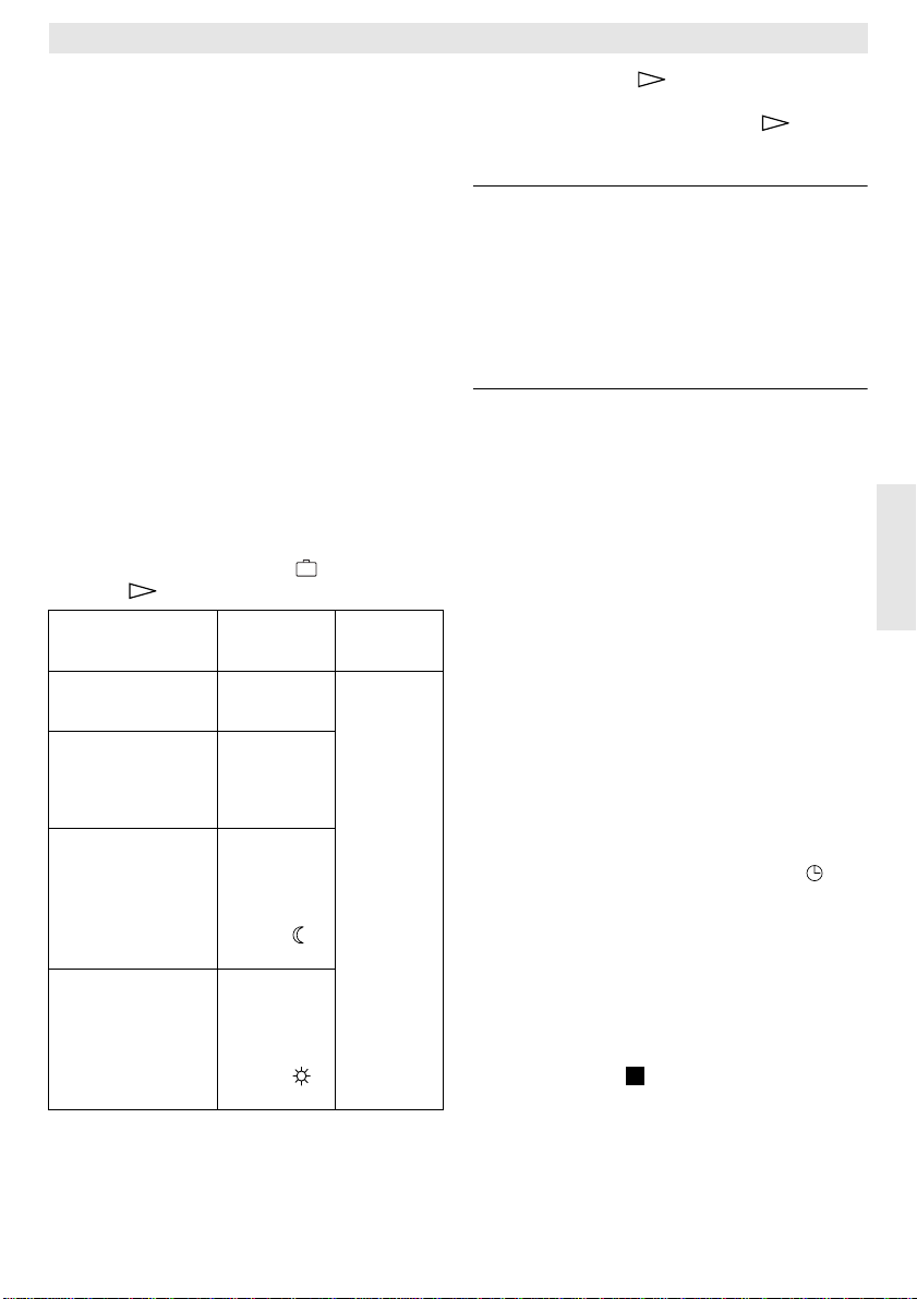
TR 200
Impostare la lingua che si desidera, operando
con il pulsante «+» (p) oppure «–» (o).
Lingue disponibili:
• T edesco/Deutsch • T urco/Türkce
• Inglese/English • Polacco/Po polsku
• Olandese/Nederlands • Ceco/Cesky
• Spagnolo/Espanol • Slovacco/Slovensky
• Italiano • Ungherese/Magyar
• Francese/FRANCAIS • Sloveno/Slovensko
• Portoghese/Portugues • Croato/Hrvatski
• Danese/Dansk • Lettone/Latviski
• Greco/ELLINIKA • Rumeno/Romaneste
Richiudete lo sportello se non intendete più
eseguire alcuna modifica del programma.
6.3 «3° livello di comando» oppure «livello di servizio tecnico»
(Riservato al personale specializzato)
Il «3°livello di comando» oppure «livello di
servizio tecnico» è accessibile impostando il
selettore (n) nella posizione e premendo il
pulsante (q) per più di 5 secondi:
Esempio di
visualizzazione
Sens. Locale +/–
21,3 °C
Sens. Remoto +/–
21,4 °C
Rid. Temp. +/–
14,6 °C
Temp. risc. +/–
19,7 °C
Descrizione
dei parametri
Calibrare la
sonda incorporata
Calibrare la
sonda esterna
(accessorio
opzionale
RF1)
Calibrare il
valore visualizzato rispetto
alla posizione
della scala
Selettore
(m)
Calibrare il
valore visualizzato rispetto
alla posizione
della scala
Selettore
(k)
Impostazioni
possibili
Operando
con il pulsante «-» (o)
oppure
«+» (p), il
valore visualizzato può
essere modificato a passi
di 0,1 K (°C)
per un massimo di
± 3 K (°C).
Tramite il pulsante (q) è possibile passare
alla successiva voce di visualizzazione. Premendo nuovamente il pulsante dopo la
voce «
Temp. risc. +/-» si esce dal «livello di ser-
vizio».
Avvertenza: tenere presente che, calibran-
do le sonde, è importante che
queste non vengano influenzate da fonti di calore esterne (es.
calore del corpo umano). Non
appena si apre lo sportello, i valori di misurazione delle sonde
vengono bloccati per consentirne la taratura.
Per annullare una determinata taratura, premere brevemente il pulsante di annullamento
C (r) in corrispondenza della rispettiva voce
visualizzata sul display. In questo modo si ritorna al valore impostato di fabbrica.
Richiudete lo sportello se non intendete più
eseguire alcuna modifica del programma.
6.4 Autonomia
Dopo almeno un giorno d’esercizio, l’orologio
programmatore ha a disposizione un’autonomia di circa 2 ore. In caso di mancanza di
energia elettrica, il display si spegne. Se l’alimentazione viene ripristinata entro le 2 ore di
autonomia, tutte le funzioni del cronotermostato TR 200 saranno nuovamente attive.
Tip
Evitare di disattivare l’alimentazione
☞
elettrica per un periodo superiore alle 2 ore.
6.5 Impostazione dell’ora legale/ora
solare
Procedere come descritto nel capitolo «impostazione dell’ora».
Non modificare le programmazioni «riscaldamento» e «riduzione di temperatura»!
6.6 Breve guida per l’uso
Nella fessura situata sul lato destro del
TR 200 si trova una breve guida per l’uso, in
cui sono descritti brevemente tutti i punti più
importanti (figura ).
2
Italiano
59
Page 60

TR 200
6.7 Cronotermostato collegato con
sonda remota RF1 (accessorio)
Collegando la sonda remota, si disattiva automaticamente la sonda incorporata nel cronotermostato ambiente.
In questo modo diventano determinanti le
condizioni di temperatura riscontrate in prossimità della sonda RF1.
Utilizzare la sonda remota se nel luogo
Tip
☞
d’installazione del cronotermostato ambiente
vi sono condizioni sfavorevoli di temperatura
che comunque non sono rappresentative per
tutto l’appartamento (esempio: radiazioni solari, correnti d’aria, vicinanza a fonti di calore,
ecc.).
6.8 Cronotermostato collegato con
comando a distanza
Il cronotermostato TR 200 è predisposto per
essere attivato con un comando a distanza.
L’applicazione più frequente si realizza abbinando il cronotermostato TR 200 ad un combinatore telefonico (non di nostra fornitura).
Italiano
Con questo sistema è possibile avviare il riscaldamento anche se si è lontani da casa,
utilizzando un qualunque telefono da cui trasmettere un codice personale.
Con questo sistema è possibile avviare il riscaldamento anche se si è lontani da casa,
utilizzando un qualunque telefono da cui trasmettere un codice personale. Per poter realizzare l’attivazione del riscaldamento a distanza, è indispensabile impostare sul cronotermostato la modalità d’esercizio che si
desidera trovare attiva al vostro rientro (funzionamento automatico o riscaldamento permanente).
Quando il contatto ON-OFF del comando a distanza è chiuso (figura ), si attiva permanentemente la funzione «notte» del cronotermostato ambiente; la spia luminosa (l) si spegne e, contemporaneamente, appare sul
display la seguente voce:
Sul display (e) appare:
8
Blocco remoto
17:53 16.5°C
Aprendo il contatto (ad esempio tramite un segnale telefonico in codice), il cronotermostato
ambiente torna ad operare secondo il programma precedentemente impostato.
Tip
Se avete precedentemente impostato il
☞
programma «riscaldamento permanente» (g)
non dimenticate, al vostro rientro, di impostare
nuovamente il cronotermostato ambiente su
«funzionamento automatico».
In caso di lunghe assenze, non trascurate il
fatto che i muri dell’abitazione potrebbero essersi molto raffreddati e che potrebbe essere
pertanto necessario anticipare l’attivazione
del riscaldamento per riportare la temperatura
ambiente ai valori desiderati.
6.9 Nuova programmazione
Volendo eseguire numerose modifiche ai programmi, si rivela spesso molto più semplice
reimpostare gli orari di attivazione/disattivazione partendo dalla programmazione impostata di serie.
Allo scopo, ruotare il selettore di programma
(n) sulla posizione . Sul display (e) appare la
voce
«Giorno +/-»; premere brevemente il pul-
sante di annullamento C (r).
Volendo cancellare tutte le impostazioni, dun-
que anche l’ora, il giorno della settimana e la
lingua sul display insieme ai punti di commutazione, è necessario premere il pulsante di
annullamento C (r) per oltre 10 secondi.
60
Page 61

TR 200
7 Segnalazioni del
cronotermostato ambiente
Spia di malfunzionamento
Il cronotermostato ambiente TR 200 è in grado di segnalare eventuali malfunzionamenti
della caldaia a cui è collegato, se quest’ultima
è dotata di quadro elettrico Bosch Heatronic.
L’anomalia di funzionamento, è segnalata dal
lampeggio della spia di controllo (l).
Sul display (e) appare:
Verif. autom.
17:53 18.0°C
Avvertenza: In questo caso attenersi alle in-
dicazioni contenute nel libretto
d’uso e manutenzione dell’apparecchio di riscaldamento oppure contattare uno dei centri
assistenza autorizzati.
8 Informazioni generali
... e consigli per risparmiare energia:
Quando si modificano le impostazioni di tem-
peratura del cronotermostato ambiente, un
microprocessore elabora i dati di funzionamento ad intervalli di 20 secondi, trasmettendo successivamente alla caldaia i segnali relativi con la tempestività necessaria.
Il locale in cui viene installato il cronotermostato ambiente determina la temperatura di
tutti gli altri locali dell’appartamento.
Per questo motivo è indispensabile che, nel
locale di riferimento, non ci siano valvole termostatiche sui radiatori o, se presenti, esse siano bloccate in posizione di tutta apertura.
La presenza di valvole termostatiche sui restanti radiatori dell’appartamento consentirà
di regolare la temperatura di ogni singolo locale.
Verificare che eventuali correnti d’aria, irraggiamento solare o esposizioni a fonti di calore,
non influenzino la funzione di regolazione del
cronotermostato ambiente.
In tal caso è consigliabile l’installazione della
sonda remota RF 1, seguendo le indicazioni
contenute nei capitoli 2.2, 5.1, 6.7.
Un abbassamento dei valori di temperatura
ambiente, consente di risparmiare notevoli
quantità d’energia.
Ad esempio, riducendo la temperatura ambiente di 1K (°C) si ottengono risparmi fino al
5%.
Non è comunque consigliabile abbassare i valori di temperatura al di sotto dei +15 °C in
quanto il conseguente raffreddamento dei
muri comporterebbe un eccessivo dispendio
di energia per ripristinare la corretta temperatura durante la successiva fase di riscaldamento. L’impostazione di valori di temperatura notevolmente superiori a quanto desiderato, non riduce il tempo di messa a regime
dell’impianto.
Evitate di lasciare costantemente socchiuse
le finestre: ciò comporterebbe una continua
fuoriuscita di calore dall’ambiente senza consentire un buon ricambio d’aria nei locali.
E’ preferibile un’aerazione breve ed intensa,
ottenibile aprendo le finestre per alcuni minuti.
Durante la fase di aerazione, impostare il cronotermostato ambiente su bassi valori di temperatura.
Italiano
61
Page 62

9 Ricerca di anomalie
Anomalia Causa Rimedio
TR 200
La temperatura ambiente
programmata non viene
raggiunta
La temperatura ambiente
programmata viene superata
Ampie oscillazioni della
temperatura ambiente
Italiano
Aumento della temperatura invece di un abbassamento
Temperatura ambiente
troppo alta nella fase di
«riduzione temperatura»
Nel locale di riferimento vi
sono installate una o più valvole termostatiche
Selettore della temperatura
di mandata della caldaia
impostato su valori troppo
bassi
Il luogo d’installazione del
cronotermostato ambiente
non è adeguato (vicinanza
ad una finestra, presenza di
correnti d’aria, ecc.)
Influenze temporanee di
fonti di calore estranee sul
cronotermostato ambiente
(radiazioni solari, lampade,
televisore, camino, ecc..)
Programmazione errata del
cronotermostato ambiente
Edificio con elevata inerzia
termica (i muri cedono
all’ambiente il calore accumulato durante la fase di
riscaldamento)
Sostituire le valvole termostatiche con valvole manuali,
oppure aprire completamente
le valvole termostatiche
Impostare il selettore su valori
più alti
Scegliere un luogo più
idoneo per l’installazione
(vedi capitolo «Montaggio»),
oppure applicare la sonda
remota RF1 (accessorio)
Scegliere un luogo più
idoneo per l’installazione
(vedi capitolo «Montaggio»),
oppure applicare la sonda
remota RF1 (accessorio)
Controllare la fascia oraria
programmata
Anticipare l’inizio della fase
«riduzione temperatura»
Il cronotermostato non
effettua alcun tipo di
regolazione
Il display non visualizza
l’ora attuale, oppure il
doppio punto non
lampeggia
62
Errato collegamento
elettrico del
cronotermostato ambiente
Breve interruzione
dell’alimentazione elettrica
Controllare il collegamento
basandosi sugli schemi di
9 10 11
fig. , ,
Spegnere e riaccendere
l’apparecchio di
riscaldamento, agendo
sull’interruttore principale
Page 63

TR 200
1 Indicações de segurança
O regulador só deve ser utilizado em ligação com os aparelhos de aquecimento, observar o respectivo plano de ligação.
O regulador não deve de maneira nenhuma ser ligado à rede de 230 V.
Antes da montagem do regulador é necessário interromper a alimentação de
tensão (230 V, 50 Hz) ao aparelho de
aquecimento.
O regulador não é apropriado para a
montagem em recintos húmidos.
2 Aplicação
O TR 200 é um regulador de temperatura ambiente com relógio digital (programa semanal;
três pontos de aquecimento e de redução por
dia da semana) para regular os aparelhos de
aquecimento a gás de regulação constante
indicados abaixo.
TYP Ligação
eléctrica
ZE/ZWE .. - 2 K... Figura não
ZE/ZWE .. - 2 A... Figura não
ZR/ZWR/ZSR...-3 Figura não
ZR/ZWR/ZSR...-4 Figura não
Aparelhos de
aquecimento com
Bosch Heatronic Figura sim
O TR 200 é recomendado para áreas de habitação até aprox. 80 m
disposições legais.
Para equipamentos com aquecimento de solo, não são apropriados reguladores de temperatura ambiente como o TR 200.
2.1 Extensão do fornecimento
Com o TR 200 ambém é fornecido um regulador de temperatura ambiente com breve instrução de serviço (Figura ).
Indicação de
avaria
a distância
activa
9
10
10
10
11
2
e corresponde às
2
2.2 Acessórios
Com o TR 200 ambém pode ser fornecido um
sensor de temperatura ambiente RF 1. Este
por exemplo é útil, quando o local de montagem do regulador não é apropriado para a
medição de montagem (veja capítulo 4).
Além disso é possível ligar um telecomando
(p. ex. em forma de um comando de telefone)
(veja capítulo 6.8).
O telecomando deve conter um contacto livre
de potencial, que é apropriado para 5 V DC.
3 Dados técnicos
Dimensões do
aparelho veja figura
Tensão nominal 24 V DC
Corrente nominal 0,03 A
Área de regulação 5…30 °C
Saída de
regulação
T emper atura ambiente
admissível 0…+40 °C
Reserva de marcha aprox. 2 horas
Tipo de protecção IP 20
contínua,
2,8…21,5 V DC
3
4 Montagem
Antes da montagem do regulador é necessário interromper a alimentação de
tensão (230 V, 50 Hz) ao aparelho de
aquecimento.
4.1 Selecção do local de montagem
Importante para a qualidade de regulação do
TR 200, é a selecção de um local de montagem apropriado. O recinto de montagem deve
ser apropriado para a regulação de temperatura de todo o equipamento de aquecimento.
Não devem ser montados válvulas de termostato nos corpos de aquecimento instalados
neste local. Ao invés disto deveriam ser montados válvulas manuais com pré-ajuste, para
que a potência do corpo de aquecimento no
recinto de montagem do TR 200 possa ser
ajustada o mais estreito possível.
Português
63
Page 64

TR 200
8
Como local de montagem deveria ser seleccionada uma parede interior, e deveria observar que não haja corrente de ar nem incidência de calor (também não por de trás, p. ex.
através de tubos vazios, paredes ocas etc.)
sobre o regulador.
Por cima e por baixo do regulador deve haver
espaço suficiente, para que o ar ambiente
possa circular pela abertura de ar sem ser impedido (superfícies listrada na figura ).
4
Se todas as condições mencionadas acima
não forem satisfeitas, é recomendado utilizar
um sensor externo de temperatura ambiente
RF 1 (acessório) e instalá-lo num local apropriado.
Ao ligar o sensor de temperatura ambiente RF
1, é automaticamente desligado o sensor
montado no regulador.
4.2 Montagem do regulador
• Soltar a parte superior (a) da base (b) , premir o gancho lateral (b1) na base e puxar a
parte superior (a) (figura ).
5
• A base (b) pode
– ser montada com dois parafusos (c) so-
bre uma tomada embutida corrente no
comércio (d) com ø 55 mm,
ou
Português
– com 4 buchas (6 mm) e parafusos
(Ø 3,5 mm) de cabeça lenticular, directamente à parede (figura );
6
observar o sentido de montagem correcto
(descrição de borne legível)!
• Realizar a ligação eléctrica de acordo (veja
capítulo 5).
• Introduzir a parte superior do regulador (a).
4.3 Montagem dos acessórios
Os acessórios de sensores exteriores de temperatura ambiente RF 1 e de interruptores à
distância (caso existentes) devem ser montados de acordo com a respectiva instrução de
instalação.
5 Ligação eléctrica
O seguinte diâmetro de potência deve ser utilizado entre o TR 200 e o aparelho de aquecimento:
Comprimento
até 20 m 0,75 mm
Comprimento
até 30 m 1,0 mm
Comprimento
superior a 30 m 1,5 mm
Considerando as disposições vigentes, é necessário utilizar no mínimo cabos eléctricos
do tipo H05 VV-....
Todas as ligações de 24 V (corrente de medição) devem ser instaladas separadas de ligações de 230 V ou 400 V, para que não haja
uma influencia inductiva (distância mínima
100 mm).
Se houver a possibilidade de influencias exteriores devido à p. ex. cabos de alta tensão, fios, estações de transformadores, aparelhos
de rádio e televisão, estações de rádio amadores, aparelhos de micro-ondas ou aparelhos semelhantes, será necessário blindar as
linhas que conduzem sinais de medição.
Deve ser seguido o respectivo plano de conexão eléctrica (figura a ).
9 11
5.1 Ligação eléctrica dos acessórios
O sensor externo de temperatura ambiente
RF 1 (caso existente), deve ser ligado como
indicado na figura
7
.
Se necessário é possível alongar as ligações
do RF 1 com um cabo com linha dupla transpostas. Desta forma é assegurado que os valores de medição do sensor não sejam influenciados.
Telecomando (caso existente) deve ser ligado como indicado na figura
nimas requeridas encontram-se no
capítulo 2.2 Acessórios.
Se o contacto do telecomando estiver fechado, o aquecimento passa para o funcionamento económico, na indicação aparece “F”.
Quando o contacto estiver aberto, o regulador
passa para o tipo de funcionamento ajustado
no regulador (figura ).
8
2
até 1,5 mm
2
até 1,5 mm
. Exigências mí-
2
2
2
64
Page 65

TR 200
6 Comando
O TR 200 possui alguns elementos de comando, que após a instalação e colocar em
funcionamento, são raramente utilizados.
Por este motivo é que os elementos de comando pouco utilizados encontram-se sob
uma capa.
Os elementos visíveis com a tampa fechada,
pertencem ao “1° nível de comando”. Todos os
outros elementos de comando formam o “2°
nível de comando” e o “3° nível de comando”
ou “Nível de serviço” para o especialista.
Todas as situações de funcionamento especiais são indicadas através de texto ou lâmpadas de controle, assim como a indicação de
avaria (apenas para aparelhos de aquecimento com Bosch Heatronic).
Com a capa fechada, é indicada a hora actual
e a temperatura ambiente medida (em passos
de 0,5-°C).
6.1 O “1° nível de comando”
20°C
15
25
3010
5
Com o botão giratório (k) é ajustada a temperatura ambiente, na qual o regulador deve
ajustado durante o funcionamento de aquecimento normal.
O regulador ajusta-se sempre nesta temperatura, quando a respectiva lâmpada de controle vermelha (l) está iluminada.
Se o botão giratório (k) está na posição “5”,
não ilumina-se a respectiva lâmpada de controle vermelha (l). O regulador ajusta-se então em aprox. 5 °C e assegura assim a protecção contra geada no recinto. Isto quer dizer
que o aquecimento está desligado acima de
6 °C.
6.1.2 As situações de funcionamento
Funcionamento automático
O ajuste básico do regulador é o funcionamento automático.
Funcionamento automático significa uma comutação automática entre o funcionamento
de aquecimento normal e o funcionamento
económico durante os períodos indicados
pelo relógio de conexão (e).
6.1.1 Botão giratório (k)
No funcionamento de aquecimento normal o
regulador ajusta-se (=“dia”) na temperatura
ajustada no botão giratório (k), a respectiva
lâmpada de controle vermelha (l) lestá permanentemente ligada.
No funcionamento económico o regulador
ajusta-se (=“Noite”) na temperatura de economia ajustada, a respectiva lâmpada de controle vermelha (l) está apagada. (Os ajustes
para a temperatura económica encontram-se
no capítulo 6.2.1)
Indicação: Cada vez que sair do funciona-
mento automático, isto será indicado através de uma lâmpada de
controle ou texto.
É possível voltar para o funcionamento automático a qualquer hora.
Tecla
“Aquecimento contínuo” (g)
Premindo a tecla (g) , é ligado o tipo de funcionamento de aquecimento contínuo.
O regulador ajusta-se continuamente na temperatura ajustada com o botão giratório (k).
A respectiva lâmpada de controle vermelha
(f) ilumina-se.
Também ilumina-se a respectiva lâmpada de
controle vermelha (l) (a não ser que o botão
giratório (k) esteja na posição “5”).
O funcionamento económico ajustado no relógio de conexão é ignorado.
O tipo de funcionamento “Aquecimento contínuo” permanece activo, até:
• a tecla (g) ser premida novamente; é
ajustado novamente para o funcionamento
automático
ou
• até a tecla (h) ser premida; é ajustado o
funcionamento económico.
Em ambos os casos, a respectiva lâmpada de
controle vermelha (f) se apaga e o regulador
aquece de acordo com a temperatura válida.
Tip
Premir esta tecla, se excepcionalmente
☞
desejar ir deitar-se mais tarde (p. ex. festa).
Mais tarde deverá comutar de volta para o
funcionamento automático.
Português
65
Page 66

TR 200
Também no caso de doenças pode ser agradável um aquecimento contínuo. Mas também não esqueça-se de comutar de volta
para o funcionamento automático.
Durante as férias de inverno ou no verão,
pode ser seleccionada uma temperatura de
aquecimento reduzida durante um prolongado perído, premindo a tecla de aquecimento
contínuo e adicionalmente reduzindo a temperatura com o botão giratório
(k).
Tecla
“Funcionamento económico” (h)
Uma pressão sobre a tecla (h) é suficiente
para comutar para o tipo de funcionamento
económico.
O regulador ajusta-se continuamente na temperatura “Temperatura económica” ajustada
com o botão giratório (O ajuste da temperatura económica encontra-se no
capítulo 6.2.1).
A respectiva lâmpada de controle amarela (i)
ilumina-se.
A respectiva lâmpada de controle vermelha (l)
está apagada.
O funcionamento de aquecimento normal
ajustado no relógio de conexão é ignorado.
Português
O tipo de funcionamento “Funcionamento
económico” permanece até
• meia noite (00.00)
ou
• até premir a tecla (h) mais uma vez; é
ajustado novamente no funcionamento au-
tomático
ou
• até premir a tecla (g); está agora
ajustado no aquecimento contínuo.
Em todos os casos a respectiva lâmpada de
controle amare-la (i) apaga-se e o regulador
aquece de acordo com as temperaturas válidas.
Tip
Utilize esta função, se desejar sair de
☞
casa (p. ex. fazer compras) e não desejar que
o apartamento continue a ser aquecido. Logo
que voltar para casa, deverá premir a
tecla (h) novamente, o regulador trabalha
novamente no funcionamento automático e
aquece de acordo com a temperatura válida.
Se sair de casa a noite ou desejar deitar-se
mais cedo, deverá premir a tecla
(h). O re-
gulador termina o funcionamento económico
à meia-noite e aquece na próxima manhã
como de costume no funcionamento automático.
6.2 O “2° nível de comando”
O “2° nível de comando” é acessível após
abrir a tampa basculante.
Abrindo a capa é automaticamente ajustado o
modo de programação. A indicação depende
da posição do interruptor giratório (n).
15°C
10
20
25
5
6.2.1 Botão giratório (m)
30
“Temperatura económica”
Com o botão giratório (m) é ajustada a temperatura ambiente, na qual o regulador deverá ajustar no funcionamento automático “Economizar” e no “Funcionamento económico”
(h).
6.2.2 Dados gerais sobre o relógio
Com o relógio é possível ligar automaticamente o aquecimento até três vêzes ao dia à
uma hora determinada e desligar automaticamente três vêzes ao dia também à uma hora
determinada.
Estes horários podem ser individualmente determinados para cada dia.
6.2.3Colocar o interruptor
giratório na posição
“Selecao Hora”
Ajustar a hora
Girar o interruptor giratório (n) para a posição
.
Indicação: Ao colocar em funcionamento ou
após prolongada falta de corrente, aparece
Seleccao Dia+/-. Neste
caso deverá ajustar o dia da semana actual, e em seguida premir a tecla (q) .
66
Page 67

TR 200
Na indicação aparece (e):
Selecao Hora +/12:00
A hora é ajustada premindo as teclas “-” (o)
ou “+” (p).
Uma leve pressão altera a hora por 1 minuto,
premindo por mais tempo, a hora é alterada
rapidamente para frente ou para trás. Neste
caso os segundos são respectivamente colocados em “0”. Logo que a tecla for solta, a
hora continua a passar normalmente.
Tip
Hora antes de 12.00 (dia) podem ser
☞
mais rapidamente ajustadas com a tecla “–”
(o).
Fechar a tampa, se não desejar realizar mais
nenhuma alteração.
Na indicação aparece (e):
17:53 21.5°C
Ajustar o dia da semana
Girar o interruptor giratório (n) para a posição
. Quando for indicado
rá premir a tecla (q). Na linha superior da
indicação (e) aparece:
Selecao Hora +/-, deve-
Seleccao Dia +/-
O dia da semana actual é ajustado premindo
a tecla “–” (o) ou “+” (p).
Se em seguida desejar ajustar a hora, deverá
premir a tecla (q).
Fechar a capa, se não desejar realizar mais
nenhuma alteração.
6.2.4 Interruptor giratório na posição “Aquecimento”
Ajustar o programa de aquecimento
Com o relógio é possível ligar automaticamente o aquecimento até três vêzes ao dia à
uma hora determinada e desligar automaticamente três vêzes ao dia também à uma hora
determinada.
Estes horários podem ser individualmente determinados para cada dia.
Também é possível ajustar as mesmas horas
para cada dia.
Para poder programar de forma efectiva, é
sensato, introduzir as horas de aquecimento
na tabela (veja capítulo 10). O programa de
aquecimento, que ocorre na maioria dos dias
(também levemente alterado), deveria ser introduzir em primeiro passo para todos os dias.
As horas divergentes podem ser alteradas em
seguida sem grande dispêndio.
Colocar o interrutor giratório (n) na posição .
Na indica-ção (e) aparece:
Seleccao Dia +/-
Premir a tecla “–” (o) ou “+” (p). Aparecem todos os
Dias da Semana (ou o dia da semana ac-
tual) na linha superior.
No ajuste todos
dia á mesma hora com “aquecimento” e todo
dia é iniciado á mesma hora com “economizar”.
Se foi seleccionado um dia da semana individual (p. ex. quinta-feira), o respectivo programa tornar-se-á válido para a hora determinada. Isto significa que a cada quinta-feira á
mesma hora é iniciado com “aquecimento” ou
“economizar”.
Um dia da semana individual é ajustado premindo as teclas “–” (o) ou “+” (p).
Entre
Domingo e Segunda-Feira é indicado todos
Dias da Semana.
Para o dia da semana/todos dias da semana
podem ser ajustadas horas de aquecimento.
Para isto deverá premir a tecla (q).
Na indicação (e) aparece:
Dias da Semana, é iniciado cada
1. Inicio Aquet
6:00
O primeiro início de aquecimento é ajustado
premindo a tecla “–” (o) ou “+” (p).
Uma breve pressão altera o horário para o início de aquecimento por 10 minutos, premindo
por mais tempo o horário movimenta-se para
frente ou para trás.
Logo que a hora desejada estiver ajustada,
deverá premir a tecla (q).
Português
67
Page 68

TR 200
Agora deve ser ajustado o primeiro início de
economia.
Na indicação (e) aparece:
1. Inicio Econo.
22:00
O desejado primeiro início de economia é
ajustado premindo a tecla “–” (o) ou “+” (p).
Uma breve pressão altera o início de economia por 10 minutos, premindo por mais tempo
o horário movimenta-se para frente ou para
trás.
Logo que a hora desejada estiver ajustada,
deverá premir a tecla (q).
Na indicação (e) aparece:
1. Inicio Aquect
--:--
Indicação: --:-- significa, que o ponto de co-
Agora é possível, se desejado, ajustar o horá-
Português
rio para o segundo início de aquecimento de
acordo com o mesmo esquema que para o
primeiro início de aquecimento.
Deverá proceder da mesma forma para o segundo início de economia, assim como se desejado, para o terceiro início de aquecimento
e de economia.
Se não forem necessários pontos de comutação, deverá premir a tecla (q) , sem alterar nada.
Se desejar anular um ponto de comutação indicado, deverá premir por instantes a tecla de
anulação C (r) com um pino. Aparece
indicação.
Logo que as horas desejadas estiverem ajustadas, deverá premir a tecla (q).
Aparece
cionar um dia individual ou um outro dia e introduzir a respectiva hora.
mutação não está ocupado, ou
seja, no caso de um ajuste de fábrica ou após uma prolongada
falta de corrente, só está ajustado
um início de aquecimento e um
início de economia.
Seleccao o Dia +/-. Agora deverá selec-
--:-- na
Indicação: Se após a programação de todos
Tip
☞
precisam ser introduzidos na sequência de
hora certa. Durante a idicação
os dias da semana, desejar alterar um certo dia da semana, aparece após uma repetida chamada
do ponto de programação “Dias
da Semana”, em todos pontos
de comutação,
Se um ponto de comutação for alterado para todos dias da semana, é anulado o programa anterior dos dias da semana e deve ser
programado novamente como já
descrito acima.
--:-- na indicação.
Os pontos de comutação de um dia não
Seleccao Dia +/-
, o regulador arruma automaticamente os pontos de comutação.
Poderá ver os pontos de comutação ajustados, procedendo como descrito acima, no entanto sem premir “–” (o) ou “+” (p).
Se desejar que seja aquecido além de meia-
noite, é anulado o último início de economia.
Este deve ser introduzido como primeiro dia
do início de economia para o próximo dia. O
regulador reconhece a sequência dos pontos
de comutação, apesar de que o primeiro início
de aquecimento é mais tarde do que o primeiro início de economia.
Se desejar que num dia da semana não seja
aquecido (p. ex. escritório, que não é utilizado
no domingo), então introduza o respectivo início de economia (se necessário no dia anterior), e anule todos os outros pontos de comutação, até que deva ser aquecido novamente.
Se desejar que num dia de semana seja
aquecido permanentemente, então introduza o respectivo início de aquecimento (se necessário no dia anterior), e anule todos os outros pontos de comutação, até que deva ser
economizado novamente.
Se desejar realizar grandes alterações no
programa, é talvez vantajoso, iniciar a partir
do programa ajustado de fábrica.
Para anular todos os pontos de comutação
pessoais, deverá proceder de acordo como
descrito acima, até que a indicação
Seleccao Dia +/- apareça. Premir então por ins-
tantes a tecla de anulação C (r).
68
Page 69

TR 200
Agora está ajustado novamente o ajuste de
fábrica (Todos os dias: 1. início de aquecimento 06:00; 1. início de economia 22:00, outro pontos de comutação
Fechar a tampa, se não desejar realizar outras alterações.
6.2.5Colocar o interruptor giratório na posição “Férias”
Ajustar para férias
Girar o interruptor giratório (n) para a posição
. Na indicação (e) aparece:
--:--).
Dias Ausente +/0
O número desejado de dias de férias é ajustado premindo as teclas “–” (o) ou “+” (p).
Uma breve pressão altera o número de dias
de férias por um dia, premindo por mais tempo, o número de dias de férias altera-se mais
rapidamente.
Indicação: O dia actual deve ser contado
Exemplo: Deseja viajar de férias durante
duas semanas, e sai de casa no sábado à tarde. No sábado à tarde em duas semanas, retornará, e o mais tardar a este horário o apartamento deve estar aquecido.
Se um pouco antes da partida, realizar a programação, os números de dias de férias é
“14” (Sábado, domingo, ...quinta-feira e sexta-feira, pois o regulador deverá aquecer neste sábado como de costume).
Após fechar a tampa aparece a indicação (e):
como dia de férias, isto significa,
que o regulador começa imediatamente com o programa de férias. O dia de retorno só é contado,
se não desejar que seja aquecido
neste dia!
14 Dias Ausente
17:53 16.5°C
O regulador regula a partir de já a temperatura ajustada no botão giratório (m). O número restante de dias é continuamente indicado.
Após o decorrer do número de dias indicado
(à meia-noite), o regulador termina automaticamente o funcionamento economico e retorna para o funcionamento automático.
Se desejar realizar outras alterações, não necessita fechar a tampa.
Tip
Observe que a temperatura ajustada no
☞
botão giratório (m) não seja nociva para os
animais domésticos e plantas dentro da ca-
sa, etc. durante o perído de férias.
Se já desejar voltar pela parte da manhã,
pode ser sensato, iniciar a aquecer a partir da
meia-noite, ao invés de aguardar até o
primeiro início de aquecimento. Neste caso
deverá premir a tecla (q), após ter
ajustado os dias de férias. Na indicação
aparece:
o tipo de funcionamento após o fim das férias
com a tecla “+” (p) ou “–” (o) no
funcionamento de aquecimento permanente
ou automático. Se tiver seleccionado o
funcionamento permanente, é aquecido na
temperatura ajustada no botão giratório (k)
a partir da meia-noite do último dia de férias.
Não se esqueça de premir a tecla (g)
quando voltar, para terminar o aquecimento
permanente.
Se o funcionamento de férias tiver que ser
interrompido antecipadamente, poderá:
premir duas vêzes a tecla (g),
ou colocar o número de dias na posição “0”
como descrito acima.
Também pode ser alcançado um aquecimento permanente por vários dias, ajustando o
número de dias como descrito acima e aumentando a temperatura de início ao valor desejado no botão giratório (m).
“Automatico +/-”
. Agora poderá ajustar
Português
69
Page 70

6.2.6Interruptor giratório
na posição i
Indicação do valor ajustado
Girar o interruptor giratório (n) para a posição
“i”. Na indicação superior (e) aparece o dia da
semana actual.
Se premir a tecla (q) , é indicado o seguinte grupo. Cada valor no grupo é , se existente,
indicado durante 5 segundos, em seguida o
regulador pula para o próximo. Se desejar ler
os valores com mais rapidez, então é possível
pular para frente com a tecla “+”- (p).
Se desejar ler os valores por mais tempo, deverá premir brevemente a tecla “–” (o), a indicação permanecerá neste parâmetro.
Premindo a tecla (q), é activada a comutação automática para o próximo parâmetro.
No primeiro grupo, aparecem na indicação
(e) os seguintes valores gerais num intervalo
de 5 segundos, valores não existentes são
pulados:
Indicação-Exemplo
(num intervalo de 5
seg.)
Temperaturas Título do 1. grupo
Português
Temp. reg. sensor
21,5 °C
Temp. no. sensor
21,0 °C
Temp. regulada
21,5 °C
Parâmetros-Descrição
Temperatura ambiente
medida no regulador “local”
só é indicada, se estiver
conectado um sensor externo
(acessório).
Temperatura ambiente
medida no sensor externo
(acessório).
Temperatura nominal, com a
qual o regulador trabalha.
TR 200
No segundo grupo, os valores do progra-
ma de aquecimento são indicados num inter-
valo de 5 segundos, valores não existentes
são pulados:
Indicaçãoexemplo
(num intervalo de
5 seg.)
Prog.
Aquecimento
Quinta-Feira Programa de aquecimento para
1. Início Aquect
6:00
1. Início Econ.
9:00
2. Início Aquect
11:30
2. Início Econ.
13:00
3. Início Aquect
17:30
3. Início Econ.
22:00
Sexta-Feira Programa de aquecimento para
Parâmetros-descrição
Título do 2. grupo
dia da semana (ou todos dias
da semana)
1. início de aquecimento
ajustado para dia de semana
1. início de economia ajustado
para dia da semana
2. início de aquecimento
ajustado para dia da semana
2. início de economia ajustado
para dia da semana
3. início de aquecimento
ajustado para dia da semana
3. início de economia ajustado
para dia da semana
próximo dia da semana etc.
Em seguida a indicação automática começa
do início, ela funciona até que o interruptor giratório (n) seja mudado de posição ou a tampa seja fechada.
Ajustar o idioma
Colocar o interruptor giratório (n) na posição i.
Manter premida a tecla “–” (o) , até aparecer
a indicação:
Sprache +/-
70
Page 71

TR 200
Ajustar o idioma desejado com a tecla “+” (p)
ou “–” (o).
Idiomas à disposição:
• Alemão/Deutsch • Turco/Türkce
• Inglês/English • Polonês/Po polsku
• Holandês/Nederlands • Checo/Cesky
• Espanhol/Espanol • Eslovaco/Slovensky
• Italiano/Italiano • Hùngaro/Magyar
• Francês/FRANCAIS • Esloveno/Slovensko
• Português/Portugues • Croata/Hrvatski
• Dinamarquês/Dansk • Letão/Latviski
• Grego/ELLINIKA • Romeno/Romaneste
Fechar a tampa, se não desejar realizar nenhuma alteração.
6.3 O “3. Nível de comando” ou
“Nível de serviço”
(Apenas no seu especialista)
O “3. nível de comando” ou “Nível de serviço”
torna-se accessível para o especialista, premindo o interruptor giratório (n) na posição
e mantendo premida a tecla (q) por mais
do que 5 segundos. Valores não existentes
são pulados:
IndicaçãoExemplo
Sonda Tempra. +/–
21,3 °C
Sonda exter. +/–
21,4 °C
Temp. Econom. +/–
14,6 °C
Temp. Aqueci. +/–
19,7 °C
Parâmetrosdescrição
Calibrar do
sensor instalado
Calibrar o
sensor
externo (acessório)
Calibrar o
valor indicado
em relação á
posição da
escala
Botão girató-
rio (m)
Calibrar o
valor indicado
em relação à
posição da
escala
Botão girató-
rio (k)
Possibilidades de ajuste
O valor indicado pode ser
alterado com
as teclas
“–” (o) ou
“+” (p) em passos de
0,1-K, por no
máximo ±3 K
Com a tecla (q) é possível mudar a indicação. Premindo novamente a tecla -durante
“Temp. Aqueci. +/–”, sai-se do “Nível de serviço”.
Indicação: Deverá obsrvar que antes de ca-
librar os sensores, estes não devem sr influenciados através de
calor externo (calor do corpo).
Logo que a tampa for aberta, os
valores de medição dos sensores
serão memorizados para a calibragem.
Para anular uma calibragem, deve ser premida brevemente a tecla de anulação (r), ou seja, o valor anterior está activo novamente.
Fechar a tampa, se não desejar realizar outras alterações.
6.4 Reserva de marcha
O relógio de conexão possui, após um funcionamento mínimo de 1 dia de funcionamento,
de uma reserva de marcha de aprox. 2 horas.
Durante uma falha de corrente eléctrica a indicação apaga-se. Se o abastecimento de
corrente voltar a funcionar dentro da reserva
de funcionamento, a indicação da hora, assim
como os inícios de aquecimento e economia
estão novamente à disposição.
Observe, que a alimentação de corren-
Tip
☞
te não seja interrompida por mais do que 2 horas (o aquecimento não deve ser desligado
durante o verão, mas deverá seleccionar uma
temperatura reduzida no regulador, veja
capítulo 6.1.2 Conselhos para aquecimento
contínuo).
6.5 Ajustar o horário de verão/inverno
Proceda como descrito no capítulo “Ajustar
a hora”!
Os pontos de comutação “Início de aquecimento” e “Início de funcionamento económico” não devem ser alterados!
6.6 Breve instrução de serviço
No compartimento do lado direito da base encontra-se uma breve instrução de serviço, na
qual encontram-se as mais importantes descrições (figura ).
2
Português
71
Page 72

TR 200
6.7 Regulador com sensor de temperatura ambiente RF 1 (acessório) ligado
Se estiver conectado um sensor de temperatura externo RF 1, o sensor instalado no regulador não tem efeito. Desta maneira, as condições de temperatura na área externa do
sensor ambiente são determinantes para a indicação de temperatura e para a regulação.
Tip
Aplicando o sensor de temperatura am-
☞
biente RF1, se no local de montagem do regulador existirem condições de medição
desfavoráveis que não valem para toda a habitação, p. ex. incidência de luz solar, funcionamento de fogão de azulejos etc.
6.8 Regulador com telecomando
(montado)
Com este interruptor adicional (não no programa de fornecimento) é possível ligar o
aquecimento à distância.
A aplicação mais comum é a utilização de um
comando telefónico. Deste modo é possível ligar o aquecimento através de um telefone,
transmitindo um código pessoal.
Antes de sair de casa, é ajustada uma situação de funcionamento no regulador, que é desejado ao voltar para casa (Automático ou
aquecimento contínuo).
Português
Então o comutador do interruptor à distância
é fechado, o regulador trabalha em “economia”, a lâmpada vermelha de controle está
fechada, “Aquecer” (l) está desligado.
Na indicação (e) aparece:
Comando telef.
17:53 16.5°C
Quando o interruptor é aberto (p. ex. através
de um sinal de telefone codificado), o regulador trabalha com o programa ajustado anteriormente.
Tip
O lar também permanece quente, mes-
☞
mo no ínicio da noite/de manhã cedo, se deixar o regulador na posição antes de sair de
casa (aquecimento contínuo) (g) e apenas em
seguida ligar o interruptor. No entanto não se
esqueça de colocar o regulador de volta na
posição “Funcionamento automático” ao voltar para casa.
No caso de longa ausência não deveria esquecer, de que a habitação (paredes etc.) podem estar fortemente arrefecidas e portanto
necessitem de mais tempo para aquecer-se.
6.9 Nova programação
Se desejar realizar maiores alterações, é
mais simples colocar o regulador na situação
de fornecimento e em seguida programar novamente todos os pontos de comutação.
Girar o interruptor giratório (n) para a posição , até aparecer
ção (e), em seguida premir brevemente a tecla de anulação C (r).
Se desejar anular todos os ajustes com os
pontos de comutação, portanto também a
hora e o dia da semana (e o idioma na indicação), deverá premir a tecla de anulação C (r)
por mais do que segundos.
Seleccao Dia +/– na indica-
7 Indicação do regulador
A indicação de avaria à distância
(não em todos os aparelho de aquecimento)
No caso de aparelhos de aquecimento Bosch
Heatronic, uma avaria no aparelho de aquecimento é transmitida ao regulador.
No caso de uma avaria do aparelho de
aquecimento, pisca a lâmpada de controle
“Aquecimento” (l).
Na indicação (e) aparece:
Yer instalacao
17:53 18.0°C
Indicação: Neste caso proceda de acordo
com as indicações na instrução
de serviço do aparelho de
aquecimento ou informe-se no
seu especialista de aquecedores.
72
Page 73

TR 200
8 Indicações gerais
... e indicações para poupar energia:
No caso de alterações dos ajustes do regula-
dor, o regulador reage atrasado. O processor
compara a cada 20 segundos todos os valores nominais e reais e realiza em seguida as
respectivas correcções com a necessária velocidade.
O recinto (recinto guia), no qual o regulador
de temperatura está instalado, determina a
temperatura nos outros recintos.
Ou seja, a temperatura no recinto guia é determinante para toda a rede de aquecimento.
Por este motivo é necessário, se no recinto
guia estiverem montados corpos de aquecimento com termostatos, que estes estejam
completamente abertos. Caso contrário as
válvulas de termostato reduzem o abastecimento de calor, apesar do regulador exigir
sempre mais calor (veja também
capítulo 4.1).
Se desejar uma temperatura reduzida nos recintos adjacentes, ou se desejar desligar
completamente o corpo de aquecimento, deverá ajustar as devidas válvulas do corpo de
aquecimento (termostático) de forma respectiva.
DJá que o recinto onde se encontra o regulador de temperatura ambiente funciona como
recinto guia, é possível que haja um aquecimento insuficiente (p. ex. devido à incidência
de raios solares, fogão de ladrilhos, etc.) dos
outros recintos (o aquecimento permanece
frio). Para solucionar este problema é possível aplicar o sensor de temperatura ambiente
RF 1 como acessório, de acordo com as indicações no capítulo 2.2, capítulo 5.1 e
capítulo 6.7.
Reduzindo a temperatura ambiente por 1 K
(°C) é possível alcançar uma economia de
energia de 5%.
No entanto não é sensato reduzir diariamente
a temperatura ambiente de recintos aquecidos abaixo de +15 °C. Durante o próximo processo de aquecimento a comodidade é reduzida devido à paredes arrefecidas. Para no
entanto alcançar um certo conforto, é então
ajustada uma temperatura ambiente mais alta
e por muitas vêzes consumido mais energia,
do que seria necessária para um aquecimento uniforme.
No caso de prédios com bom isolamento, é
possível que não seja alcançada a temperatura económica ajustada. Apesar disto é poupada energia, pois o aquecimento permanece
desligado.
Neste caso poderá iniciar o funcionamento
económico antecipadamente.
Para ventilar os recintos não deverá deixar as
janelas na posição inclinada. Desta forma escapa continuamente calor do recinto, sem
que a qualidade do ar ambiente melhore. Evite portanto uma ventilação permanente!
É melhor ventilar de forma curta e intensiva
(Abrir completamente a janela).
Durante a ventilação deverá ajustar o regulador de temperatura num valor reduzido.
Português
73
Page 74

9 Procura de avarias
Reclamação Causa Solução
TR 200
A temperatura ambiente
ajustada não é alcançada
A temperatura ambiente
ajustada é ultrapassada
Oscilações de temperatura ambiente muito altas
Aumento de temperatura
Português
ao invés de redução
Temperatura ambiente
demasiadamente altra no
funcionamento económico
A(s) válvula(s) de termostato estão instaladas no
recinto de montagem do
regulador
O selector de temperatura
de avanço no aparelho de
aquecimento está ajustada
num valor muito baixo
O local de montagem do
regulador é desfavorável, p.
ex. parede e xterna, perto de
janelas, corrente de ar...
Influência temporária de
aquecimento externo no
regulador, p. ex. devido à
raios solares, iluminação do
recinto, aparelhos de TV,
lareiras, etc.
A hora do dia no relógio de
conexão está ajustada correctamente
Alto acúmulo de calor no
prédio
A válvula de termostato deve
ser substituida por uma válvula manual ou deverá abrir
completamente a válvula de
termostato
Ajustar o selector de temperatura de avanço num v alor mais
alto
Seleccionar um local de montagem mais favorável (veja
capítulo Montagem) ou aplicar
um sensor de temperatura
ambiente (acessório)
Seleccionar um local de montagem mais favorável (veja
capítulo Montagem) ou
aplicar um sensor de temperatura ambiente externo (acessório)
Controlar o ajuste
Seleccionar mais cedo o início
do funcionamento económicoa
Regulação errada
ou nenhuma regulação
Nenhuma indicação
ou a indicação não reage
74
Ligação errada do regulador Controlar de acordo com o
plano de ligação e se necessário corrigir
Uma curta falha de corrente Desligar e ligar o interruptor
principal do aparelho de aquecimento
Page 75

TR 200
1 Veiligheidsvoorschriften
De regelaar mag uitsluitend worden gebruikt in combinatie met de genoemde
gasverwarmingsapparaten. Het desbetreffende aansluitschema moet in acht
worden genomen.
In geen geval mag de regelaar worden
aangesloten op het 230 V stroomnet.
Vóór de montage van de regelaar moet
de spanningstoevoer (230 V, 50 Hz)
naar het verwarmingsapparaat worden
onderbroken.
De regelaar is niet geschikt voor de
montage in vochtige ruimten.
2 Gebruik
De TR 200 is een ruimtetemperatuurregelaar
met digitale schakelklok (weekprogramma;
drie verwarmings- en drie verlagingsschakelpunten per weekdag) voor de regeling van de
hieronder genoemde continu geregelde gasverwarmingsapparaten.
TYPE Elektr.
ZE/ZWE .. - 2 K... afb. nee
ZE/ZWE .. - 2 A... afb. nee
ZR/ZWR/ZSR...-3 afb. nee
ZR/ZWR/ZSR...-4 afb. nee
Verwarmingsappa-
raten met
Bosch Heatronic afb. ja
De TR 200 wordt geadviseerd bij een woonoppervlak tot ca. 80 m
aansluiting
9
10
10
10
11
2
en voldoet aan de wet-
telijke voorschriften.
Voor installaties met vloerverwarming zijn
ruimtetemperatuurregelaars als de TR 200
niet geschikt.
2.1 Meegeleverd
Meegeleverd bij de TR 200 wordt een in de
ruimtetemperatuurregelaar ingeschoven korte gebruiksaanwijzing (afbeelding ).
Afstandstoringsaanduiding actief
2
2.2 Toebehoren
Bij de TR 200 kan een externe ruimtetemperatuursensor RF 1 worden geleverd. Deze
kan bijvoorbeeld zinvol worden gebruikt als de
montageplaats van de regelaar voor de temperatuurmeting ongeschikt is (zie hoofdstuk 4).
Bovendien kan een extere afstandschakelaar (bijvoorbeeld via de telefoon te bedienen)
worden aangesloten (zie hoofdstuk 6.8).
De afstandschakelaar moet een potentiaalvrij
contact hebben dat geschikt is voor 5 V DC.
3 Technische gegevens
Afmetingen apparaat zie afbeelding
Nominale spanning 24 V DC
Nominale stroom 0,03 A
Regelbereik 5…30 °C
Regeluitgang continu, 2,8…21,5 V DC
T oegestane
omgevingstemperatuur 0…+40 °C
Gangreserve ca. 2 uur
Isolatiesoort IP 20
3
4 Montage
Vóór de montage van de regelaar moet
de spanningstoevoer (230 V, 50 Hz)
naar het verwarmingsapparaat worden
onderbroken.
4.1 Keuze van de montageplaats
Belangrijk voor de regelkwaliteit van de
TR 200 is de keuze van een geschikte montageplaats. De montageruimte moet geschikt
zijn voor de temperatuurregeling van de hele
verwarmingsinstallatie. Op de daar geïnstalleerde verwarmingsradiatoren mogen geen
thermostaatknoppen zijn gemonteerd. In
plaats daarvan moeten handmatig bediende
knoppen met voorinstelling worden ingebouwd, zodat het vermogen van de verwarmingsradiator in de montageruimte van de
TR 200 zo nauwkeurig mogelijk kan worden
ingesteld.
Nederlands
75
Page 76

TR 200
Kies als montageplaats bij voorkeur een binnenmuur en let erop dat geen tocht of warmtestraling (ook niet van achteren, bijvoorbeeld
door een lege buis of holle muur) op de regelaar kan inwerken.
Onder en boven de regelaar moet voldoende
plaats aanwezig zijn om de ruimtelucht ongehinderd door de ventilatieopening te laten circuleren (gearceerd oppervlak in
afbeelding ).
4
Als niet aan alle bovengenoemde voorwaarden is voldaan, wordt geadviseerd om gebruik
te maken van de externe ruimtetemperatuursensor RF 1 (toebehoren) en deze aan te
brengen op een geschiktere plaats.
Als de ruimtetemperatuursensor RF 1 wordt
aangesloten, wordt automatisch de in de regelaar ingebouwde sensor uitgeschakeld.
4.2 Montage van de regelaar
• Het bovenstuk (a) van de sokkel (b) losmaken, haken (b1) aan zijkant van sokkel indrukken en bovenstuk (a) lostrekken
(afbeelding ).
5
• De sokkel (b) kan naar keuze
– met twee schroeven (c) op een normale
inbouwcontactdoos (d) van ø 55 mm
worden gemonteerd,
of
– met vier pluggen (6 mm) en lenskop-
schroeven (Ø 3,5 mm) rechtstreeks op
de muur worden geschroefd
Nederlands
(afbeelding );
6
daarbij op de juiste montagerichting letten
(klemopschrift leesbaar)!
• Elektrische aansluiting overeenkomstig uitvoeren (zie hoofdstuk 5).
• Bovenstuk (a) van regelaar vaststeken.
4.3 Montage van het toebehoren
Het toebehoren externe ruimtetemperatuursensor RF 1 en afstandschakelaar (indien
aanwezig) volgens de wettelijke voorschriften
en het bijbehorende inbouwvoorschrift monteren.
5 Elektrische aansluiting
De volgende kabeldiameter moet worden gebruikt van de TR 200 naar het verwarmingsapparaat:
Lengte tot 20 m 0,75 mm2 tot 1,5 mm
Lengte tot 20 m 1,0 mm2 tot 1,5 mm
Lengte meer dan 30 m 1,5 mm
Met inachtneming van de geldende voorschriften moeten voor de aansluiting minstens
elektrische kabels van het type H05 VV-...
worden gebruikt.
Alle leidingen met 24 V (meetstroom) moeten
gescheiden worden geïnstalleerd van leidingen met 230 of 400 V, zodat geen inductieve
beïnvloeding kan plaatsvinden (minimumafstand 100 mm).
Indien inductieve externe invloeden kunnen
optreden, bijvoorbeeld door sterkstroomkabels, bovenleidingen, transformatorhuisjes,
radio- en televisietoestellen, magnetrons en
zenders van radioamateurs, moeten de leidingen voor het meetsignaal worden afgeschermd.
Het desbetreffende elektrische aansluitschema (afbeelding tot )
houden.
5.1 Elektrische aansluiting van het
toebehoren
Externe ruimtetemperatuursensor RF 1 (indien aanwezig) als in afbeelding getoond
aansluiten.
Indien nodig kunnen de leidingen van de RF 1
met een kabel met verdrilde tweelingsleidingen worden verlengd. Daardoor wordt gewaarborgd dat de meetwaarden van de sensor niet worden beïnvloed.
Afstandschakelaar (indien geïnstalleerd) aansluiten zoals getoond op de afbeelding . Zie
voor de minimumeisen hoofdstuk 2.2 Toebehoren.
Als het schakelcontact van de afstandschakelaar gesloten is, wordt de verwarming in de
spaarstand geschakeld, in het display verschijnt „F”. Als het schakelcontact geopend is,
wordt de op de regelaar ingestelde functie
overgenomen (afbeelding ).
9 11
moet worden aange-
7
8
8
2
2
2
76
Page 77

TR 200
6 Bediening
De TR 200 bezit enkele bedieningselementen
die na installatie en gebruikneming nog maar
zelden hoeven worden gebruikt.
Daarom zijn alle bedieningselementen die
slechts zelden hoeven te worden gebruikt met
een klepje afgeschermd.
De bedieningselementen die zichtbaar zijn als
het klepje gesloten is, horen bij het zogenaamde „1e bedieningsniveau”. Alle andere
bedieningselementen vormen het tweede bedieningsniveau en de servicestand voor de
verwarmingsmonteur.
Alle speciale bedrijfstoestanden worden aangeduid door tekst in het display of door controlelampjes, net als de storingsaanduiding (alleen bij de verwarmingsapparaten met Bosch
Heatronic).
Als het klepje gesloten is, worden de actuele
en de gemeten ruimtetemperatuur (in stappen
van 0,5 °C) weergegeven.
6.1 Het „1e bedieningsniveau”
20°C
15
25
3010
5
Met de draaiknop (k) wordt de ruimtetemperatuur ingesteld die de regelaar bij normale
verwarmingsfunctie moet regelen.
De regelaar regelt de verwarming altijd op
deze temperatuur als het bijbehorende rode
controlelampje (l) brandt.
Als de draaiknop (k) op „5” staat, brandt het
bijbehorende rode controlelampje (l) niet. De
regelaar regelt de verwarming dan op ongeveer 5 °C en waarborgt daardoor vorstbescherming in de ruimte. Dat betekent dat de
verwarming boven 6 °C is uitgeschakeld.
6.1.2 De bedrijfstoestanden
Automatische functie
De basisinstelling van de regelaar is automatische functie.
Automatische functie betekent automatische
wisseling tussen normale verwarmingsfunctie
en spaarstand op de tijden die met de schakelklok (e) zijn ingesteld.
6.1.1 Draaiknop (k)
De regelaar regelt de verwarming in de normale verwarmingsfunctie (=„Dag”) op de met
de draaiknop (k) ingestelde temperatuur,
de bijbehorende rode controlelamp (l) brandt
permanent.
De regelaar regelt de verwarming bij de
spaarstand (=„Nacht”) op de ingestelde
spaartemperatuur, de bijbehorende rode controlelamp (l) brandt niet. (Zie voor de instelling
van de spaartemperatuur hoofdstuk 6.2.1)
Opmerking: Als de automatische functie
wordt verlaten, wordt dit altijd
door een controlelampje of door
een tekst weergegeven.
Er kan op elk moment worden
teruggekeerd naar de automatische functie.
Toets „Continu verwarmen” (g)
Door een druk op de toets (g) wordt de
functie continu verwarmen ingeschakeld.
De regelaar regelt de verwarming continu met
de op de draaiknop (k) ingestelde temperatuur.
De bijbehorende rode controlelamp (f) brandt.
Ook het bijbehorende rode controlelampje (l)
brandt (behalve als de draaiknop (k) op
stand „5” staat).
De op de schakelklok ingestelde spaarstand
wordt genegeerd.
De functie „Continu verwarmen” blijft in stand
tot:
• de toets (g) nogmaals wordt ingedrukt;
de automatische functie is dan weer ingesteld
of
• de toets (h) wordt ingedrukt; de spaar-
stand is dan ingesteld.
In beide gevallen gaat de bijbehorende rode
controlelamp (f) uit en de regelaar verwarmt
volgens de dan geldende temperatuur.
Tip
Druk op deze toets als u bij wijze van
☞
uitzondering later gaat slapen (bijvoorbeeld
na een feestje). Later weer terugschakelen
naar automatische functie.
Ook bij ziekte kan continu verwarmen aangenaam zijn. Vergeet ook dan echter niet om terug te schakelen naar automatische functie.
Nederlands
77
Page 78

TR 200
Tijdens de wintervakantie of in de zomer kan
gedurende lange tijd een lagere verwarmingstemperatuur worden gekozen door de toets
continu verwarmen in te drukken en bovendien de temperatuur op de draaiknop
(k) la-
ger in te stellen.
Toets „Spaarstand” (h)
Door een druk op de toets (h) wordt de
spaarstand ingeschakeld.
De regelaar regelt de verwarming continu met
de op de draaiknop „Spaartemperatuur” ingestelde temperatuur (zie voor de instelling
van de spaartemperatuur hoofdstuk 6.2.1).
De bijbehorende gele controlelamp (i) brandt.
De bijbehorende rode controlelamp (l)is uit.
De op de schakelklok ingestelde normale ver-
warmingsstand wordt genegeerd.
De functie „Spaarstand” blijft in stand tot:
• middernacht (00.00 uur)
of
• de toets (h) nogmaals wordt ingedrukt;
de automatische functie weer ingesteld
of
• de toets (g) wordt ingedrukt;
dan is continu verwarmen ingesteld.
In alle gevallen gaat de bijbehorende gele
controlelamp (i) uit en de regelaar verwarmt
volgens de dan geldende temperaturen.
Tip
Gebruik deze functie als u de woning
☞
verlaat (bijvoorbeeld om boodschappen te
Nederlands
doen) en de woning niet meer hoeft worden
verwarmd. Zodra u terugkomt, drukt u de toets
(h) opnieuw in, de regelaar werkt weer volgens de automatische functie en verwarmt
volgens de dan geldende temperatuur.
Als u uw woning 's avonds verlaat of een
keer vroeg naar bed gaat, drukt u op de knop
(h). De regelaar beëindigt de spaarstand om
middernacht en verwarmt de volgende morgen
als gewoonlijk met de automatische functie.
6.2 Het „2e bedieningsniveau”
Het „2e bedieningsniveau” is toegankelijk na
het openen van het klepje.
Als het klepje wordt geopend, wordt automatisch de programmeermodus ingesteld. De
aanduiding is afhankelijk van de stand van de
draaischakelaar (n).
78
15°C
10
20
25
5
6.2.1 Draaiknop
30
„Spaartemperatuur” (m)
Met de draaiknop (m) wordt de ruimtetemperatuur ingesteld waarmee de regelaar in de automatische functie bij „Sparen” in de „Spaarstand” (h) de verwarming moet regelen.
6.2.2 Algemene opmerkingen
over de klok
Dankzij de schakelklok kunt u maximaal driemaal per dag de verwarming op een vooraf
bepaald tijdstip automatisch laten inschakelen
en driemaal per dag op een vooraf bepaald
tijdstip automatisch laten uitschakelen.
Deze tijdstippen kunnen voor elke dag apart
worden bepaald.
6.2.3Draaischakelaar in stand
„Uur instellen”
Tijd instellen
De draaischakelaar (n) in de stand draaien.
Opmerking: Bij ingebruikneming of bij lang-
durige onderbreking van de
stroom verschijnt
Dag kiezen +/-. In
dit geval de actuele dag instellen, en vervolgens toets (q)
indrukken.
In het display (e) verschijnt:
Uur instellen +/12:00
De tijd wordt ingesteld door het indrukken van
de toetsen „-” (o) en „+” (p).
Door kort indrukken wordt de tijd met 1 minuut
versteld, door lang indrukken loop de tijd snel
vooruit of achteruit. Daarbij worden de seconden telkens op „0” gezet. Zodra de toets wordt
losgelaten, loopt de tijd gewoon verder.
Tip
Tijden voor 12.00 uur ('s middags) kun-
☞
nen met de toets „-” (o) sneller worden ingesteld.
Page 79

TR 200
Klepje sluiten als geen wijzigingen meer hoeven worden uitgevoerd.
In het display (e) verschijnt:
17:53 21.5°C
Weekdag instellen
De draaischakelaar (n) in de stand draaien.
Als
Uur instellen +/- wordt aangegeven, toets
(q) indrukken. In de bovenste regel van het
display (e) verschijnt:
Dag kiezen+/-
De actuele weekdag wordt ingesteld door het
indrukken van de toetsen „–” (o) of „+” (p).
Als vervolgens de tijd moet worden ingesteld,
toets (q) indrukken.
Klepje sluiten als geen wijzigingen meer hoeven worden uitgevoerd.
6.2.4 Draaischakelaar in stand
„Verwarming”
Verwarmingsprogramma instellen
Dankzij de schakelklok kunt u maximaal driemaal per dag de verwarming op vooraf bepaalde tijdstippen automatisch laten inschakelen en maximaal driemaal per dag op vooraf
bepaalde tijdstippen automatisch laten uitschakelen.
Deze tijdstippen kunnen voor elke dag apart
worden bepaald.
Het is ook mogelijk om voor elke dag dezelfde
tijden in te stellen.
Om effectief te kunnen programmeren is het
zinvol de verwarmingstijden in de tabel op
BLZ. 98 in te vullen. Het verwarmingsprogramma dat op de meeste dagen (ook in licht
gewijzigde vorm) voorkomt, moet dan in de
eerste stap voor alle dagen worden ingevoerd. De afwijkende tijden kunnen dan zonder veel moeite worden gewijzigd.
De draaischakelaar (n) in stand draaien. In
het display (e) verschijnt:
Dag kiezen+/-
Toets „–” (o) of „+” (p) indrukken. In de bovenste regel verschijnt
le dag).
In de instelling
op dezelfde tijd begonnen met „Verwarmen”
en elke dag op dezelfde tijd begonnen met
„Sparen”.
Als één dag (bijvoorbeeld donderdag) is gekozen, geldt altijd op deze dag en op de opgegeven tijd het bijbehorende programma. Dat betekent dat op elke donderdag om dezelfde tijd
wordt begonnen met „Verwarmen” of „Sparen”.
Een afzonderlijke dag wordt ingesteld door
het indrukken van de toetsen „–” (o) of „+” (p).
Tussen
gen weergegeven.
Voor de weergegeven weekdag / alle weekdagen kunnen de verwarmingstijden worden
ingesteld. Daarvoor toets (q) indrukken.
In het display (e) verschijnt:
Zondag en Maandag worden Alle weekda-
Alle weekdagen (of de actue-
Alle weekdagen wordt elke dag
1e begin verw.
6:00
De gewenste tijd voor het eerste verwarmingsbegintijdstip wordt ingesteld door het indrukken van de toetsen „–” (o) en „+” (p).
Door een korte druk op een toets wordt het
verwarmingsbegintijdstip met 10 minuten versteld. Als de toets langer wordt ingedrukt,
loopt het tijdstip snel vooruit of achteruit.
Als de gewenste tijd is ingesteld, toets (q)
indrukken.
Nu moet het bijbehorende eerste spaarstandbegintijdstip worden ingesteld.
In het display (e) verschijnt:
1e begin sparen
22:00
Het gewenste eerste spaarstandbegintijdstip
wordt ingesteld door het indrukken van de
toetsen „–” (o) en „+” (p).
Door een korte druk op een toets wordt het
spaarstandbegintijdstip met 10 minuten versteld. Als de toets langer wordt ingedrukt,
loopt het tijdstip snel vooruit of achteruit.
Als de gewenste tijd is ingesteld, toets (q)
indrukken.
Nederlands
79
Page 80

TR 200
In het display (e) verschijnt:
2e begin verw.
--:--
Opmerking: --:-- betekent dat dit schakelpunt
Nu kan indien gewenst de tijd voor het tweede
verwarmingsbegintijdstip volgens hetzelfde
schema worden ingesteld als voor het eerste
verwarmingsbegintijdstip.
Voor het tweede spaarstandbegintijdstip, indien gewenst, voor het derde verwarmingsbegintijdstip en het spaarstandbegintijdstip op
dezelfde wijze te werk gaan.
Als schakelpunten niet nodig zijn, de toets
(q) indrukken zonder iets te verstellen.
Als een aangegeven schakelpunt moet worden gewist, de wistoets C (r) met een spits
voorwerp kort indrukken. In het display wordt
--:-- weergegeven.
Als de gewenste tijden zijn ingesteld, toets
(q) indrukken.
Dag kiezen +/- wordt weergegeven. Nu zoals bo-
ven beschreven een dag of een andere dag
kiezen en de bijbehorende tijden intoetsen.
Opmerking: Als na de programmering voor
Nederlands
niet is bezet, dat wil zeggen dat
in de fabrieksinstelling of na
langdurige onderbreking van de
stroom alleen een verwarmingsbegintijdstip en een spaarstandbegintijdstip is ingesteld.
alle weekdagen één dag is gewijzigd, wordt na het opnieuw
oproepen van het programmeerpunt
schakelpunten
weergegeven. Als vervolgens
een schakelpunt voor alle weekdagen wordt gewijzigd, wordt
het oorspronkelijke programma
van de afzonderlijke weekdagen
gewist en moet er opnieuw worden geprogrammeerd zoals
hierboven beschreven.
„Alle weekdagen” bij alle
--:-- in het display
Tip
De schakelpunten van een dag hoeven
niet in de juiste tijdsvolgorde te worden ingetoetst. Als Dag kiezen +/- wordt weergegeven,
zet de regelaar de schakelpunten automatisch
in dezelfde volgorde.
U kunt de ingestelde schakelpunten bekijken
door te werk te gaan zoals hierboven beschreven, maar zonder „–” (o) en „+” (p) in te drukken.
Als na middernacht moet worden verwarmd,
vervalt het laatste spaarstandbegintijdstip.
Toets deze voor de volgende dag als eerste
spaarstandbegintijdstip in. De regelaar herkent de volgorde van de schakelpunten, hoewel het eerste verwarmingsbegintijdstip later
ligt dan het eerste spaarstandbegintijdstip.
Als op een bepaalde dag nooit hoeft te worden
verwarmd (bijvoorbeeld een kantoor dat op
zondag niet wordt gebruikt) voert u het bijbehorende spaarstandbegintijdstip (eventueel op de
dag daarvoor) in en wist u alle andere schakelpunten tot opnieuw moet worden verwarmd).
Als op een bepaalde dag continu moet wor-
den verwarmd, voert u het bijbehorende verwarmingsbegintijdstip (eventueel op de dag
daarvoor) in en wist u alle andere schakelpunten tot opnieuw moet worden begonnen met
de spaarstand.
Als u een programma uitgebreid wilt wijzigen,
is het soms gunstiger om uit te gaan van het
in de fabriek ingestelde programma.
Om alle persoonlijke schakelpunten te wijzigen, handelt u zoals boven beschreven tot de
aanduiding
Druk daarna kort op de wistoets C (r).
Daarna is weer de fabrieksinstelling (Alle dagen: 1. Verwarming op 06:00; 1. Verwarming
af 22:00, overige schakelpunten
steld.
Klepje sluiten als geen wijzigingen meer hoeven worden uitgevoerd.
Dag kiezen +/- wordt weergegeven.
--:--) inge-
80
Page 81

TR 200
6.2.5Draaischakelaar in stand
„Vakantie”
Vakantie instellen
Draaischakelaar (n) in stand draaien. In
het display (e) verschijnt:
Vakant. dagen +/0
Het gewenste aantal vakantiedagen wordt ingesteld door het indrukken van de toetsen
„–” (o) en „+” (p).
Door kort indrukken wordt het aantal vakantiedagen met 1 dag versteld, door langer indrukken wordt het aantal dagen sneller veranderd.
Opmerking: De actuele dag moet worden
meegeteld als vakantiedag. Dat
wil zeggen dat de regelaar onmiddellijk met het vakantieprogramma begint. De dag van de
thuiskomst wordt alleen meegeteld als er op deze dag niet hoeft
te worden verwarmd.
Voorbeeld: U wilt twee weken vakantie houden en verlaat op zaterdagnamiddag uw woning. U hebt uw thuiskomst gepland op zaterdagmiddag twee weken later. De woning
moet dan weer warm zijn.
Als u kort voor vertrek de vakantie intoetst, is
het aantal vakantiedagen „14” (zaterdag, zondag, ... donderdag en vrijdag, want de regelaar moet immers op deze zaterdag weer zoals gewoonlijk verwarmen).
Na het sluiten van het klepje verschijnt in het
display (e):
14 dagen vakant.
17:53 16.5°C
De regelaar regelt met onmiddellijke ingang
met de op de draaiknop (m) ingestelde temperatuur. Het resterende aantal dagen wordt
voortdurend weergegeven. Na het verstrijken
van het ingevoerde aantal dagen (om middernacht) beëindigt de regelaar automatisch de
spaarstand en keert deze terug naar de automatische functie.
Als u nog meer wijzigingen wilt uitvoeren,
hoeft u het klepje nog niet te sluiten.
Tip
Denkt u eraan dat de op de draaiknop
☞
(m) ingestelde temperatuur voor uw huisdie-
ren, kamerplanten etc. voor de gehele duur
van uw vakantie onschadelijk moet zijn.
Als u reeds voor de middag wilt terugkeren,
kan het zinvol zijn om reeds vanaf
middernacht met het verwarmen te beginnen
in plaats van te wachten tot aan het eerste
verwarmingsbegintijdstip. Druk in dit geval
nadat u de vakantiedagen hebt ingesteld op
de toets (q). In het display verschijnt:
„Automatisch +/-”
einde van uw vakantie met de toets „+” (p) of
„–” (o) instellen op continu verwarmen of
automatisch. Als u continu verwarmen hebt
gekozen, wordt na de laatste vakantiedag
vanaf middernacht verwarmd op de op de
draaiknop (k) ingestelde temperatuur.
Vergeet niet bij uw terugkeer de toets (g) in
te drukken om continu verwarmen te
beëindigen.
Als de vakantiefunctie voortijdig moet worden
opgeheven kan:
toets (g) tweemaal achter elkaar worden in-
gedrukt,
of het aantal dagen zoals boven beschreven
op „0” worden gezet.
Continu verwarmen gedurende een aantal dagen is mogelijk als u het aantal dagen instelt
zoals boven beschreven en u de spaartemperatuur met de draaiknop (m) verhoogt tot de
gewenste waarde.
. U kunt nu de werking na het
Nederlands
81
Page 82

6.2.6Draaischakelaar in stand i
Ingestelde waarden laten weergeven
Draaischakelaar (n) in stand „i” draaien. In het
bovenste display (e) verschijnt de actuele
dag.
Als u de toets -(q) indrukt, wordt de volgende groep weergegeven. Elke waarde in de
groep wordt, als deze aanwezig is, gedurende
5 seconden weergegeven, daarna springt de
regelaar naar de volgende. Als u de waarden
sneller wilt lezen, kunt u met de toets „+”- (p)
verdergaan.
Als u de waarden langer wilt lezen, drukt u
kort op de toets „–” (o). Het display blijft dan
staan op deze parameter.
Door het indrukken van de toets (q) wordt
het automatisch verderschakelen naar de volgende parameter weer geactiveerd.
In de eerste groep worden de volgende algemene waarden met een frequentie van 5 seconden in het display (e), weergegeven. Niet
aanwezige waarden worden overgeslagen:
Displayvoorbeeld
(tussenpozen van
5 sec.)
Temperaturen Titel van de eerste groep
Ruimtetemp. hier
21,5 °C
Nederlands
Ruimtetemp. afst
21,0 °C
Gewenste temp.
21,5 °C
Parameterbeschrijving
Gemeten ruimtetemperaturen bij de regelaar „hier“
wordt alleen aangegeven als
een externe voeler (toebehoren) is aangesloten.
Gemeten ruimtetemperatuur bij
externe voeler (toebehoren).
Gewenste temperatuur
waarmee de regelaar werkt.
TR 200
In de tweede groep worden de waarden van
het verwarmingsprogramma met tussenpo-
zen van 5 seconden weergegeven. Niet aanwezige waarden worden overgeslagen:
Displayvoorbeeld
(tussenpozen
van 5 sec.)
Schakeltijden Titel van de tweede groep
Donderdag Verw armingsprogramma voor
1e begin verw.
6:00
1e begin sparen
9:00
2e begin verw.
11:30
2e begin sparen
13:00
3e begin verw.
17:30
3e begin sparen
22:00
Vrijdag Verw armingsprogramma voor
Parameterbeschrijving
weekdag (of Alle weekdagen)
Ingestelde eerste verwarmingsbegintijdstip voor weekdag
Ingesteld eerste spaarstandbegintijdstip voor weekdag
Ingestelde tweede verwarmingsbegintijdstip voor weekdag
Ingestelde tweede spaarstandbegintijdstip voor weekdag
Ingestelde derde verwarmingsbegintijdstip voor weekdag
Ingestelde derde spaarstandbegintijdstip voor weekdag
volgende dag etc.
Daarna begint de automatische weergave
weer van voren. Deze loopt tot de draaischakelaar (n) wordt versteld of het klepje wordt
gesloten.
Taal instellen
Draaischakelaar (n) in stand i draaien.
Toets „–” (o) ingedrukt houden tot deze weer-
gave verschijnt:
Sprache +/-
82
Gewenste taal instellen met toets „+” (p) of
„–” (o).
Page 83

TR 200
Beschikbare talen:
• Duits/Deutsch • T urks/Türkce
• Engels/English • PoolsPo polsku
• Nederlands • Tsjechisch/Cesky
• Spaans/Espanol • Slowaaks/Slov ensky
• taliaans/Italiano • Hongaars/Magyar
• Frans/FRANCAIS • Sloweens/Slovensko
• Portugees/Portugues • Kroatisch/Hrvatski
• Deens/Dansk • Lets/Latviski
• Grieks/ELLINIKA • Roemeens/Romaneste
Klepje sluiten als geen wijzigingen meer hoeven worden uitgevoerd.
6.3 Servicestand
(voor de verwarmingsmonteur)
Tot de servicestand voor de verwarmingsmonteur krijgt u toegang als u de draaischakelaar (n) in stand zet en de toets (q) langer dan 5 seconden ingedrukt houdt. Niet
aanwezige waarden worden overgeslagen:
Displayvoorbeeld Parameter-
Ruimtevoeler +/–
21,3 °C
Afst. voeler +/–
21,4 °C
Spaartemp. +/–
14,6 °C
Verw. temp. +/–
19,7 °C
beschrijving
Calibreren van
de ingebouwde voeler
Calibreren van
de externe
voeler (toebehoren)
Calibreren van
de aangegeven waarde
ten opzichte
van de schaalverdelingsstand
Draaiknop
(m)
Calibreren van
de aangegeven waarde
ten opzichte
van de schaalverdelingsstand
Draaiknop
(k)
Instelmogelijkheid
De aangegeven
waarde
kan met de
toetsen
„–” (o) of
„+” (p) n
stappen
van 0,1-K
max. ±3 K
worden
veranderd
Met de toets -(q) gaat u door naar de volgende weergave. Als de toets bij de aanduiding
„Verw. t emp.” +/– nogmaals wordt inge-
drukt, wordt de servicestand verlaten.
Opmerking: Er moet op worden gelet dat
voor een calibratie van de voelers deze niet door externe
warmte (lichaamswarmte) mogen worden beïnvloed. Zodra
de klep wordt geopend, worden
de meetwaarden van de voelers
voor de calibratie vastgehouden.
Om een calibratie op te heffen, moet in de servicestand bij de desbetreffende aanduiding
kort de wistoets C (r) worden ingedrukt. De
oorspronkelijke waarde is dan weer actief.
Klepje sluiten als geen wijzigingen meer hoeven worden uitgevoerd.
6.4 Gangreserve
De schakelklok beschikt na minstens een dag
te zijn gebruikt over een gangreserve van ca.
2 uur. Als de stroom uitvalt, gaat het display
uit. Als de stroom weer terugkeert binnen de
gangreserve, zijn de aanduiding van de tijd,
en de begintijden van de verwarming en de
spaarstand weer beschikbaar.
Tip
Let erop dat de stroomvoorziening nooit
☞
langer dan 2 uur wordt onderbroken (de verwarming in de zomer niet uitzetten, maar op
de regelaar een lage temperatuur instellen;
zie hoofdstuk 6.1.2 Advies voor continu verwarmen).
6.5 Zomer- en wintertijd instellen
Ga te werk zoals beschreven in het hoofdstuk
„Tijd instellen”.
De schakelpunten „begin verwarmen” en „begin sparen” niet wijzigen!
6.6 Korte gebruiksaanwijzing
In het vak aan de rechterzijde van de sokkel
bevindt zich de korte gebruiksaanwijzing
waarin alle belangrijke zaken kort worden beschreven (afbeelding ).
2
Nederlands
83
Page 84

TR 200
6.7 Regelaar met aangesloten
ruimtetemperatuursensor RF 1
(toebehoren)
Als de externe ruimtetemperatuurvoeler RF 1
is aangesloten, is de in de regelaar ingebouwde voeler zonder functie. Daardoor is de temperatuur bij de externe temperatuurvoeler
voor de temperatuuraanduidingen voor de regeling bepalend.
Tip
Gebruik de ruimtetemperatuurvoeler
☞
RF1 als de meetomstandigheden op de montageplaats van de regelaar ongunstig zijn, zoals rechtstreeks zonlicht, nabijheid van een
warmtebron, etc.
6.8 Regelaar met aangesloten
afstandschakelaar
(extern)
Door deze extra schakelaar (niet door leverbaar) kan de verwarming op afstand worden
ingeschakeld.
De meest gebruikelijke toepassing is met een
via de telefoon te bedienen afstandschakelaar. Daarmee kan via elke telefoon door het
kiezen van een persoonlijke code de verwarming worden ingeschakeld.
Voor het verlaten van het huis wordt op de regelaar de functie ingesteld die bij terugkeer
wordt gewenst (automatisch of continu verwarmen).
Daarna wordt de afstandschakelaar gesloten.
De regelaar werkt in de spaarstand. De rode
controlelamp (l) is uit.
Nederlands
In het display (e) verschijnt:
Tel. vergrendeld
17:53 16.5°C
Als de schakelaar wordt geopend (bijvoorbeeld door een code via de telefoon), werkt de
regelaar met het eerder ingestelde programma.
Tip
De woning is ook laat op de avond of
☞
vroeg in de ochtend lekker warm als u de regelaar voor het verlaten van uw huis in de
stand „Continu verwarmen” (g) zet en dan
pas de schakelaar sluit. Vergeet niet de regelaar na uw terugkeer weer op „Automatische
functie” te zetten.
Als u lang afwezig bent, houdt er dan rekening
mee dat een woning die langdurig koel is geweest (muren etc.) vrij lang nodig heeft om
warm te worden.
6.9 Nieuwe programmering
Als uitgebreide wijzigingen moeten worden
uitgevoerd, is het vaak het eenvoudigst de regelaar in de oorspronkelijke toestand terug te
zetten en dan alle schakelpunten opnieuw in
te voeren.
De draaischakelaar (n) in stand draaien tot
in het display (e)
geven, vervolgens wistoets C (r) kort indrukken.
Als alle instellingen, dus ook de tijd en weekdag (en de taal in het display) met de schakelpunten moeten worden gewist, moet de wistoets C (r) langer dan 10 seconden worden ingedrukt.
Dag kiezen +/– wordt weerge-
7 Melding van de regelaar
Afstandstoringsaanduiding
(niet bij alle verwarmingsapparaten)
Bij de verwarmingsapparaten met Bosch Hea-
tronic wordt een storing van het verwarmingsapparaat doorgegeven aan de regelaar.
Bij een storing van het verwarmingsappa-
raat knippert het controlelampje „Verwarmen” (l).
In het display (e) verschijnt:
Installie test
17:53 18.0°C
Opmerking: Ga in dit geval te werk volgens
de aanwijzingen in de ge-
bruiksaanwijzing van het verwarmingsapparaat of neem
contact op met uw verwarmingsinstallateur.
84
Page 85

TR 200
8 Algemene opmerkingen
... en tips om energie te besparen:
Als de instellingen van de regelaar worden
veranderd, reageert de regelaar met een tijdsvertraging. De processor vergelijkt elke 20 seconden alle gewenste en werkelijke waarden
en voert daarna de desbetreffende correcties
met de vereiste snelheid uit.
De ruimte (hoofdruimte) waarin de ruimtetemperatuurregelaar is ingebouwd bepaalt de
temperatuur voor de overige ruimten.
Dat betekent dat de ruimtetemperatuur in de
hoofdruimte de bepalende temperatuur voor
het complete verwarmingsnet is.
Daarom moeten thermostaatgeregelde verwarmingsradiatoren altijd geheel worden geopend als deze in de hoofdruimte zijn gemonteerd. De thermostaatknoppen reduceren anders de warmtetoevoer terwijl de regelaar om
steeds meer warmte vraagt (zie ook hoofdstuk 4.1).
Als in de bijruimten een lagere temperatuur
wordt gewenst of de verwarmingsradiator geheel moet worden uitgezet, moeten daar de
(thermostatische) radiatorknoppen overeenkomstig worden ingesteld.
Omdat de ruimte waarin de ruimtetemperatuurregelaar is gemonteerd als regelruimte
werkt, kan externe warmte (zoals rechtstreeks
zonlicht of een warmtebron) leiden tot een onvoldoende verwarming van de overige ruimten (verwarming blijft koud). Voor het oplossen van dit probleem kan als toebehoren de
ruimtetemperatuurregelaar RF 1 volgens de
aanwijzingen in hoofdstuk 2.2, hoofdstuk 5.1
en hoofdstuk 6.7 worden gebruikt.
Door het verlagen van de ruimtetemperatuur
overdag of 's nachts kan veel energie worden
bespaard.
Het verlagen van de ruimtetemperatuur met
1 K (°C) kan een energiebesparing van 5% tot
gevolg hebben.
Het is echter niet zinvol om de temperatuur in
een dagelijks verwarmde ruimte beneden +15
°C te laten dalen. Als de ruimte de volgende
keer wordt verwarmd, wordt het verwarmen
namelijk door de afgekoelde muren vertraagd.
Om een behaaglijke temperatuur te krijgen
wordt dan vaak een hogere temperatuur ingesteld en daardoor meer energie verbruikt dan
bij een gelijkmatige warmtetoevoer het geval
zou zijn geweest.
Bij een goede warmte-isolatie van het gebouw
wordt mogelijkerwijs de ingestelde temperatuur van de spaarstand niet bereikt. Toch
wordt energie bespaard, omdat de verwarming uitgeschakeld blijft.
In dit geval kunt u ook het schakeltijdstip voor
het begin van de spaarstand eerder instellen.
Bij het ventileren het venster niet op een kier
laten staan. Daardoor wordt voortdurend
warmte aan de ruimte onttrokken zonder dat
de ruimtelucht noemenswaardig wordt verbeterd. Voorkom daarom permanente ventilatie.
Het is beter om kort, maar intensief te luchten
(raam geheel openen).
Tijdens het luchten temperatuurregelaar op
lagere waarde instellen.
Nederlands
85
Page 86

9 Fouten opsporen
Klacht Oorzaak Oplossing
TR 200
Ingestelde ruimtetemperatuur wordt niet bereikt
Ingestelde ruimtetemperatuur wordt overschreden
Te grote temperatuurschommelingen
Temperatuurstijging in
plaats van -daling
In de spaarstand een te
hoge ruimtetemperatuur
V erkeerde
of geen regeling
Nederlands
Geen weergave of displa y
reageert niet
Thermostaatknop(pen) in
montageruimte van de regelaar geïnstalleerd.
Aanvoertemperatuurkeuzeknop op verwarmingsapparaat te laag ingesteld
Montageplaats van de regelaar ongunstig, bijvoorbeeld
buitenmuur, vlakbij venster
of op plaats met tocht…
Tijdelijke inwerking van
warmte op de regelaar, bijvoorbeeld door zonlicht,
kunstlicht, televisietoestel,
haard etc.
Actuele tijd op de schakelklok verkeerd ingesteld
Grote warmte
opslag van het gebouw
V erkeerde bedrading van de
regelaar
Stroom is gedurende zeer
korte tijd onderbroken
geweest
Thermostaatknop laten vervangen door handmatig
bediende knop of thermostaatknop geheel openen.
Keuzeknop voor aanvoertemperatuur hoger instellen
Betere montageplaats kiezen
(zie hoofdstuk Montage) of
externe ruimtetemperatuursensor gebruiken (toebehoren)
Betere montageplaats kiezen
(zie hoofdstuk Montage) of
externe ruimtetemperatuursensor gebruiken (toebehoren)
Instelling
controleren
Begin van spaarstand vroeger
kiezen
Controleren of bedrading volgens aansluitschema verloopt
en indien nodig wijzigen
Hoofdschakelaar van het verwarmingsapparaat uit- en
weer inschakelen
86
Page 87

TR 200
1 Emniyet Kurallar∂
Bu termostat, yaln∂zca aµaπ∂da belirtilen
ECA kombi cihazlar∂nda kullan∂labilir.
∑lgili baπlant∂ µemas∂ dikkate al∂nmal∂d∂r.
Termostat, 220 V µebekeye kesinlikle
baπlanmamal∂d∂r.
Termostat baπlanmadan önce kombi
cihaz∂ gerilim beslemesi (220 V, 50 Hz)
kesilmelidir.
Bu termostat, nemli ortamlara montaj
için uygun deπildir.
2 Kullan∂m Sahas∂
TR 200, digital program saatli bir oda
termostat∂ olup, aµaπ∂da belirtilen, sürekli güç
regülasyonlu ECA kombi cihazlar∂n∂n ∂s∂
kontrolü için geliµtirilmiµtir.
Kombi Tipi Elektrik
Baπlant∂s∂
ZWE 24 - 2 K Ωema Hay∂r
ZWE 24 - 2 A Ωema Hay∂r
Bosch-Heatronic
Ωema Evet
Üniteli Kombiler
TR 200, 80 m
2
'ye kadar olan oturma mahalleri
için önerilir.
TR 200 gibi oda termostatlar∂, zeminden
∂s∂tmal∂ tesisatlar için uygun olmay∂p, bu tür
tesisatlarda, d∂µ hava termostat∂ kullan∂m∂
tavsiye olunur.
2.1 Ambalaj Kutusu Muhteviyat∂
TR 200 Oda Termostat∂ + Özet Kullanma
K∂lavuzu (Bk. Resim ).
2
2.2 Aksesuar
TR 200 ile birlikte kullan∂ma yönelik olarak
ekstern (harici) bir s∂cakl∂k sensörü (RF 1)
sipariµi de mümkündür (opsiyonel). Bu
sensörün kullan∂m∂, örneπin TR 200 montaj
mahalinin s∂cakl∂k ölçümüne uygun olmamas∂
halinde gündeme gelebilecektir (Bk.
Bölüm 4).
Bundan baµka, sisteme bir uzaktan kumanda
µalteri (örn. telefonla kumanda) baπlant∂s∂ da
mümkündür (Bk. 6.8).
Bu µalter, 5 V DC için uygun olan,
potensiyalsiz bir kontaπa sahip olmal∂d∂r.
„Kombi Ar∂za
Göstergesi“
aktif
9
10
11
3 Teknik Özellikler
Cihaz Ölçüleri
Nominal Gerilim 24 V DC
Nominal Ak∂m 0,03 A
Regülasyon Aral∂π∂ 5…30 °C
Termostat Ç∂k∂µ∂ Sürekli,
Rezerve Çal∂µma Süresi 0…+40 °C
Koruma Türü Yakl. 2 Saat
Sertifikasyon IP 20
Bk. Resim
2,8…21,5 V DC
3
4 Montaj
Termostat∂n montaj∂ndan önce kombi
cihaz∂na olan gerilim beslemesi (220 V,
50 Hz) kesilmelidir.
4.1 Montaj Mahali Seçimi
TR 200'ün regülasyon kalitesi için, uygun bir
montaj mahali seçimi çok önemlidir. Cihaz∂n
monte edileceπi oda, kalorifer tesisat∂n∂n
s∂cakl∂k regülasyonu için uygun olmal∂d∂r. Bu
odadaki radyatörlerde termostatik radyatör
vanas∂ bulunmamal∂d∂r. Bu radyatörlerin ∂s∂l
gücünün mümkün olduπunca ayarlanamaz
olmas∂n∂ temin amac∂yla, termostatik radyatör
vanas∂ yerine, ön ayarl∂ manuel radyatör
vanalar∂ tercih edilmelidir.
Montaj yeri olarak mümkün olduπunca bir iç
duvar seçilmeli ve termostat∂n, hava
ak∂m∂ndan veya ∂s∂dan etkilenmemesine
dikkat edilmelidir (cihaz∂n arkas∂ndan da olsa
bu tür bir etkileµim olmamal∂d∂r: örn. boµ bir
boru veya duvar oyuπu nedeniyle).
Oda havas∂n∂n bir engelle karµ∂laµmadan
cihaz∂n hava menfezinden sirküle olabilmesi
için termostat∂n alt ve üst k∂sm∂nda yeterli yer
b∂rak∂lmal∂d∂r (Bk. Resim 'teki taral∂ alan).
4
Yukar∂da an∂lan koµullar∂n tümü
saπlanam∂yorsa, bu durumda, RF 1 ekstern
(harici) s∂cakl∂k sensörü, uygun bir yer
seçilmek suretiyle kullan∂lmal∂d∂r (opsiyonel
aksesuar).
RF 1 harici sensörün baπlanmas∂ halinde,
termostat içindeki dahili sensör otomatik
olarak devre d∂µ∂ kalacakt∂r.
87
Türkçe
Page 88

TR 200
4.2 Termostat∂n Montaj∂
• Termostat kapaπ∂n∂ (a), yan taraflardaki
t∂rnaklar∂ (b1) içeriye doπru itmek suretiyle
konsoldan (b) çekerek ç∂kart∂n (Bk.
Resim ).
5
• Konsol (b), isteπe baπl∂ olarak aµaπ∂daki
alternatif yöntemlerle duvara monte
edilebilir:
– ø 55 mm'lik s∂va alt∂ bir priz kutusuna (d)
2 civata (c) ile montaj (Bk. Resim ),
veya
– 4 dübel (6 mm) ve mercimek baµl∂ civata
(ø 3,5 mm) ile direkt olarak duvara
montaj (Bk. Resim );
6
• Elektrik baπlant∂s∂n∂ belirtildiπi gibi yap∂n
(Bk. Bölüm 5).
• Termostat kapaπ∂n∂ (a) yerine tak∂n.
4.3 Opsiyonel Aksesuar Montaj∂
Harici oda s∂cakl∂k sensörünü (RF 1) ve
uzaktan kumanda µalterini (örn. telefon
µalteri), yasal hükümlere ve ilgili montaj
talimatlar∂na uygun olarak monte edin.
5 Elektrik Baπlant∂s∂
TR 200 - Kombi aras∂ndaki kablo kesitleri
aµaπ∂daki gibi olmal∂d∂r:
20 m'ye kadar 0,75 mm2 - 1,5 mm
30 m'ye kadar 1,0 mm2 - 1,5 mm
30 m'den daha uzun 1,5 mm
Elektrik kablosu kalitesi için, yürürlükte olan
yerel talimatlar dikkate al∂nmal∂d∂r.
Endüktif etkileµim olmamas∂ için bütün 24 V
kablolar∂ (ölçüm ak∂m∂), 220 V veya 380 V
Türkçe
ileten kablolardan ayr∂ olarak döµenmelidir
(min. mesafe 100 mm).
Kuvvetli ak∂m kablolar∂, tramvay telleri, trafo
istasyonlar∂, radyo - TV cihazlar∂, amatör
telsiz istasyonlar∂, mikro dalga cihazlar∂, v.s.
gibi endüktif d∂µ etkiler söz konusu ise, bu
durumda, ölçüm sinyali ileten kablolar, izoleli
olarak çekilmelidir.
Elektrik baπlant∂s∂nda, ilgili µema dikkate
al∂nmal∂d∂r (Bk. Resim - - ).
9 10 11
5.1 Opsiyonel Aksesuarlar∂n Elektrik
Baπlant∂s∂
Mevcut olmas∂ halinde harici oda s∂cakl∂k
sensörü (RF 1), Resim 'ye uygun olarak
7
baπlanmal∂d∂r.
∑htiyaç halinde RF 1'in kablolar∂, burmal∂ ikili
bir kablo ile uzat∂labilir. Bu sayede sensörün
ölçüm deπerleri etkilenmemiµ olacakt∂r.
Mevcut olmas∂ halinde uzaktan kumanda
6
µalteri (örn. telefon µalteri) ise, Resim 'e
8
uygun olarak baπlanmal∂d∂r. Gerekli asgari
koµullar için Bölüm 2.2 (Aksesuar) dikkate
al∂nmal∂d∂r.
Uzaktan kumanda µalteri µalt kontaπ∂n∂n
kapal∂ olmas∂ halinde, ∂s∂tma devresi,
ekonomik iµletmeye geçer ve göstergede „F“
görüntüye gelir. Kontaπ∂n aç∂k olmas∂ halinde
ise, termostatta ayarlanan iµletme tarz∂na
geçilir (Resim ).
8
6 Termostat∂n Kullan∂m∂/
Kumandas∂
TR 200, montaj ve iµletmeye alma iµleminden
sonra ender olarak kullan∂lan bir tak∂m
kumanda elemanlar∂na sahiptir.
Bu yüzden, çok az kullan∂lacak olan tüm
kumanda elemanlar∂ bir klape ile kapat∂lm∂µt∂r.
Klape kapal∂yken görünür olan kumanda
2
elemanlar∂ 1. kumanda düzlemini, diπer tüm
2
elemanlar ise 2. kumanda düzlemini ve servis
2
teknisyeni için olan 3. kumanda düzlemini
(servis düzlemini) teµkil etmektedir.
Tüm özel iµletim durumlar∂, displayde text ile
veya kontrol ledleriyle gösterilmekte olup,
Bosch-Heatronic üniteli kombilerde ar∂za
göstergesi de aktiftir.
Klape kapal∂yken, displayde aktüel saat ve
ölçülen oda s∂cakl∂π∂ (0,5 °C'l∂k ad∂mlarla)
görüntüdedir.
6.1 1. „Kumanda Düzlemi“ (Bk. Resim )
20°C
15
25
3010
5
6.1.1 Kalorifer Kumanda
Düπmesi (k)
Bu düπmeyle (k), normal kalorifer ∂s∂tmas∂
iµletmesinde, termostat∂n regüle etmesi
gereken oda s∂cakl∂π∂ seçimi yap∂lmaktad∂r.
1
88
Page 89

TR 200
Bu seçimden sonra termostat, k∂rm∂z∂ kontrol
lâmbas∂ (l) yand∂π∂ sürece, sürekli bu
s∂cakl∂πa uygun µekilde regülasyon
yapacakt∂r.
Düπme (k) „5“ konumunda ise, k∂rm∂z∂
kontrol lâmbas∂ (l) yanmaz. Bu durumda
termostat 5 °C ' a göre regülasyon yaparak
donma tehlikesini önler (kalorifer ∂s∂tmas∂
devre d∂µ∂d∂r).
6.1.2 Termostat ∑µletme Alternatifleri
Otomatik ∑µletme
Termostat∂n temel iµletme ayar∂ otomatik
iµletmedir.
Otomatik iµletmenin anlam∂, program saati (e)
ile belirlenen zamanlara uygun olarak, normal
∂s∂tma iµletmesi ve ekonomik iµletme aras∂nda
otomatik dönüµümdür.
Normal ∂s∂tma iµletmesinde (= „Gündüz“)
termostat, kumanda düπmesinde (k)
ayarlanan s∂cakl∂πa göre regülasyon yapar ve
k∂rm∂z∂ kontrol lâmbas∂ (l) sürekli yanar.
Ekonomik iµletmede (= „Gece“) termostat,
ayarlanan ekonomik s∂cakl∂πa göre
regülasyon yapar ve k∂rm∂z∂ kontrol
lâmbas∂ (l) yanmaz (ekonomik s∂cakl∂k ayar∂
için Bölüm 6.2.1'e bak∂n∂z).
Aç∂klama: Otomatik iµletmeden her ç∂k∂µ, bir
kontrol lâmbas∂yla veya text ile
gösterilmekte olup, otomatik
iµletmeye geri dönüµ her zaman
mümkündür.
Butonu „Sürekli Is∂tma“ (g)
Bu butona (g) bas∂ld∂π∂nda, sürekli ∂s∂tma
iµletmesi devreye girmektedir.
Termostat, kumanda düπmesinde (k)
ayarlanan s∂cakl∂πa uygun olarak sürekli
regülasyon yapar.
K∂rm∂z∂ kontrol lâmbas∂ (f) yanar.
Ayr∂ca diπer k∂rm∂z∂ kontrol lâmbas∂ da (l)
yanar (kumanda düπmesinin (k) „5“
konumunda bulunmas∂ durumunda yanmaz).
Program saatinde ayarlanan ekonomik
iµletme dikkate al∂nmaz.
Sürekli ∂s∂tma iµletmesi:
• butonuna (g) tekrar bas∂l∂ncaya kadar
(bu durumda tekrar otomatik iµletme
ayarlanm∂µ olur).
veya
• butonuna (h) bas∂l∂ncaya kadar
(bu durumda ekonomik iµletme ayarlanm∂µ
olur) devam eder.
Her iki durumda da k∂rm∂z∂ kontrol lâmbas∂ (f)
söner ve termostat, bundan sonra geçerli
olacak s∂cakl∂πa göre regülasyona baµlar.
Tip
Bu butona, normalden geç yat∂lacaksa
☞
(örn. bir parti verilmesi halinde) bas∂lmal∂,
daha sonra otomatik iµletmeye tekrar geri
dönülmelidir.
Hastal∂k hallerinde de sürekli ∂s∂tma
iµletmesine gerek duyulabilir. Ancak, daha
sonra tekrar otomatik iµletmeye geri
dönülmelidir.
K∂µ tatilinde veya yaz∂n, sürekli ∂s∂tma
butonuna (g) basmak ve ilaveten kumanda
düπmesiyle (k) s∂cakl∂π∂ düµürmek
suretiyle, uzunca bir zaman için düµük
s∂cakl∂k iµletmesi seçimi de yapmak
mümkündür.
Butonu „Ekonomik ∑µletme“ (h)
Bu sar∂ butona (h) bas∂ld∂π∂nda, ekonomik
iµletme devreye girmektedir.
Termostat, kumanda düπmesinde (m)
ayarlanan s∂cakl∂πa uygun olarak sürekli
regülasyon yapar (ekonomik iµletme s∂cakl∂k
ayar∂ için 6.2.1 bölümüne bak∂n).
Sar∂ kontrol lâmbas∂ (i) „Ekonomik ∑µletme“
yanar.
K∂rm∂z∂ kontrol lâmbas∂ (l) „Kalorifer Devrede“
sönüktür.
Program saatinde (e) ayarl∂ olan normal
∂s∂tma iµletmesi dikkate al∂nmaz.
Ekonomik iµletme:
• Gece yar∂s∂na kadar (saat 00.00)
veya
• butonuna (h) tekrar bas∂l∂ncaya kadar (bu
durumda tekrar otomatik iµletme
ayarlanm∂µ olur)
veya
• butonuna (g) bas∂l∂ncaya kadar (bu
durumda sürekli ∂s∂tma ayarlanm∂µ olur)
devam eder.
Bu üç durumda da sar∂ kontrol lâmbas∂ (i)
söner ve termostat, bundan sonra geçerli
olacak s∂cakl∂πa göre regülasyona baµlar.
Türkçe
89
Page 90

Tip
Bu fonksiyonu, program d∂µ∂ olarak evi
terkedecekseniz (örn. al∂µveriµ nedeniyle) ve
ev art∂k ∂s∂t∂lmayacak ise kullan∂n. Eve geri
döndüπünüzde butonuna (h) tekrar bas∂n,
termostat yeniden otomatik iµletmede
çal∂µmaya baµlayacak ve ayarl∂ s∂cakl∂πa
uygun olarak regülasyon yapacakt∂r.
Ωayet akµamlar∂ d∂µar∂ya ç∂kacaksan∂z veya
erken yatacaksan∂z butonuna (h) bas∂n.
Termostat, ekonomik iµletmeyi gece yar∂s∂
sona erdirir ve ertesi sabah otomatik
iµletmeyle ∂s∂tmaya devam eder.
6.2 „2. Kumanda Düzlemi“
2. kumanda düzlemine klape aç∂ld∂π∂nda
ulaµ∂lmaktad∂r.
Klapenin aç∂lmas∂yla otomatik olarak
programlama modülü devreye girer. Display,
program seçim µalteri (n) konumuna göre, en
son ayarlanan deπeri gösterir.
15°C
10
20
25
5
6.2.1 Kumanda Düπmesi
30
„Ekonomik ∑µletme“ (m)
Bu düπmeyle (m), termostat∂n otomatik
iµletmede, „Ekonomi“ de ve „Ekonomik
∑µletme“ de (h) regüle etmesi gereken oda
s∂cakl∂π∂ seçimi yap∂l∂r.
6.2.2 Program Saati
Program saati; kaloriferi, günde üç defaya
kadar, belirli bir saatte otomatik olarak
çal∂µt∂rmaya ve günde üç kez, belirli bir saatte
otomatik olarak devreden ç∂karmaya imkân
saπlar.
Bu zaman noktalar∂, her gün için ayr∂ ayr∂
programlanabilir.
Türkçe
6.2.3Program Seçim Ωalteri ( )
Saatin Ayarlanmas∂
Program seçim µalterini (n) „ “ konumuna
getirin.
Aç∂klama: ∑µletmeye almada veya uzun süreli
Konumunda
elektrik kesintisinde „
Gün Secimi +/-“
görüntüye gelir. Bu durumda
haftan∂n aktüel gününü ayarlay∂n
(Bk. Sayfa 102) ve sonra „ “ (q)
butonuna bas∂n.
TR 200
Displaye (e) aµaπ∂daki görüntü gelir:
Saat ayari+/12:00
Saat ayar∂, „–“ (o) veya „+“ (p) butonlar∂na
basmak suretiyle yap∂labilir.
Butonlara k∂sa bir süre bas∂l∂nca saat ayar∂
1 dakika deπiµir, uzun süreli bas∂l∂nca ise saat
ayar∂, ileri veya geri olmak üzere h∂zla deπiµir.
Bu esnada saniyeler „0“ a ayarlan∂r. Buton
b∂rak∂l∂nca saat çal∂µmaya baµlar.
Tip
12.00 (öπle) ' den önceki saat ayar∂, „–“
☞
(o) butonuyla daha h∂zl∂ yap∂labilmektedir.
Saat ayar∂ tamamlan∂nca klapeyi tekrar
kapat∂n.
Displaye (e) aµaπ∂daki görüntü gelir.
17:53 21.5°C
Haftan∂n Günü Ayar∂
Program seçim µalterini (n) „ “ konumuna
getirin. Displayde „
Saat Ayar∂ +/-'“ görüntüye
geldiπinde „ “ (q) butonuna bas∂n.
Displayin (e) üst sat∂r∂na aµaπ∂daki görüntü
gelir:
Gün Secimi +/-
Haftan∂n aktüel günü, „–“ (o) veya „+“ (p)
butonlar∂na basmak suretiyle ayarlan∂r.
Bu iµlemden sonra saat ayar∂ yap∂lacak ise
„“ (q) butonuna bas∂lmal∂d∂r.
Ayar tamamlan∂nca klapeyi tekrar kapat∂n.
6.2.4 Program Seçim Ωalteri „ “
Konumunda
Is∂tma Program∂n∂n Ayarlanmas∂
Program saati ; kaloriferi, günde üç defaya
kadar, belirli bir saatte otomatik olarak
çal∂µt∂rmaya ve yine günde üç defaya kadar,
belirli bir saatte otomatik olarak devreden
ç∂karmaya imkân saπlar.
Bu zaman noktalar∂, her gün için ayr∂ ayr∂
programlanabilir.
Her gün için ayni saatlerin ayarlanmas∂ da
mümkündür.
90
Page 91

TR 200
Efektif bir programlama yapabilmek için,
∂s∂tma zamanlar∂n∂n 110. sayfadaki tabloya
yaz∂lmas∂nda fayda vard∂r. En s∂k kullan∂lacak
olan ∂s∂tma program∂, ilk ad∂m olarak bütün
günler için girilmelidir. Bu iµlemden sonra,
farkl∂l∂k arzeden diπer zamanlar kolayl∂kla
deπiµtirilebilir.
Program seçim µalterini (n) „ “ konumuna
getirin.
Displaye (e) aµaπ∂daki görüntü gelir:
Gün Secimi +/-
„–“ (o) veya „+“ (p) butonuna bas∂n. Displayin
üst sat∂r∂nda Hergün (veya haftan∂n aktüel
günü) görüntüye gelir.
Hergün ayar∂nda, haftan∂n her günü ayni
saatte „Is∂tma“ ve yine haftan∂n her günü ayni
saatte „Ekonomik Is∂tma“ ile baµlama söz
konusudur.
Haftan∂n sadece bir gününün (örn. Perµembe)
seçilmesi halinde, sürekli olarak haftan∂n bu
gününde ve belirlenmiµ olan saatte, ilgili
program geçerli olacakt∂r. Yâni her Perµembe
günü ayni saatte „Is∂tma“ veya „Ekonomik
Is∂tma“ baµlayacakt∂r.
Haftan∂n günü ayar∂, „–“ (o) veya „+“ (p)
butonlar∂na basmak suretiyle yap∂l∂r.
Pazar ve Pazartesi aras∂nda Hergün
görüntüye gelir.
Displayde görüntüye gelen gün veya haftan∂n
tüm günleri için ∂s∂tma zamanlar∂ ayarlanabilir.
Bunu yapmak için „ “ (q) butonuna bas∂n.
Displaye (e) aµaπ∂daki görüntü gelir:
1. Isitma Basl.
6:00
Arzulanan ilk ∂s∂tma baµlang∂ç zaman∂, „–“ (o)
veya „+“ (p) butonlar∂na basmak suretiyle
programlan∂r.
Butonlara k∂sa süreli bas∂l∂nca, ∂s∂tma
baµlang∂ç zaman∂ 10 dakika deπiµir, uzun
süreli bas∂l∂nca ise, ileri veya geri olmak üzere
h∂zla deπiµir.
Arzu edilen zaman ayarlan∂nca, „ “ (q)
butonuna bas∂n.
Ωimdi art∂k ilk „Ekonomik Is∂tma Baµlang∂c∂“
n∂n ayarlanmas∂ gerekir.
Displaye (e) aµaπ∂daki görüntü gelir:
Eko. Isit. Basl.
6:00
Arzulanan ilk ekonomik ∂s∂tma baµlang∂c∂,
„–“ (o) veya „+“ (p) butonlar∂na basmak
suretiyle programlan∂r.
Butonlara k∂sa süreli bas∂l∂nca, ekonomik
∂s∂tma baµlang∂ç zaman∂ 10 dakika deπiµir,
uzun süreli bas∂l∂nca ise, ileri veya geri olmak
üzere h∂zla deπiµir.
Arzu edilen zaman ayarlan∂nca, „ “ (q)
butonuna bas∂n.
Displaye (e) aµaπ∂daki görüntü gelir:
2. Isitma Basl.
--:--
Aç∂klama: --:-- iµareti, bu µalt noktas∂n∂n henüz
Ωimdi art∂k, µayet arzu ediliyorsa, ilk ∂s∂tma
baµlang∂c∂nda olduπu gibi, ayni µemaya göre
ikinci ∂s∂tma baµlang∂ç zaman∂ ayarlanabilir.
∑kinci ekonomik ∂s∂tma baµlang∂c∂ için veya
istenmesi halinde üçüncü ∂s∂tma ve ekonomik
∂s∂tma baµlang∂çlar∂ için ayni µekilde hareket
edilebilir.
Ωalt noktalar∂na ihtiyaç duyulmamas∂ halinde,
herhangi bir deπiµiklik yapmadan „ “ (q
butonuna bas∂n.
Görüntüye gelen bir µalt noktas∂n∂n silinmesi
isteniyorsa, k∂sa süreli olmak üzere bir pim ile
„C'“ (r) butonuna bas∂n. Displayde,
görüntüye gelecektir.
Arzulanan zamanlar ayarlan∂nca, „ “ (q)
butonuna bas∂n.
Displayde
art∂k, yukar∂da izah edildiπi gibi, tek bir gün
veya diπer bir gün seçimi yap∂l∂p, ilgili
zamanlar programlanabilir.
boµ olduπunu ifade eder, yâni
fabrika ayar∂nda veya uzun süreli
elektrik kesintisinden sonra sadece
1 ∂s∂tma baµlang∂c∂ ve 1 ekonomik
∂s∂tma baµlang∂c∂ ayarlanm∂µt∂r.
--:-- iµareti
Gün Secimi +/- görüntüye gelir. Ωimdi
Türkçe
91
Page 92

TR 200
Aç∂klama: Haftan∂n tüm günleri için
Tip
☞
zamansal olarak doπru s∂rada
programlanmas∂na gerek yoktur. Gün Secimi +/-
görüntüdeyken termostat, µalt noktalar∂n∂
otomatik olarak düzenler.
„–“ (o) veya „+“ (p) butonlar∂na basmaks∂z∂n,
yukar∂da izah edildiπi gibi hareket etmek
suretiyle, ayarlanan µalt noktalar∂n∂
gözlemleyebilirsiniz.
Gece yar∂s∂ndan sonra da ∂s∂tma yap∂lacak
ise, son ekonomik ∂s∂tma baµlang∂c∂n∂n
programlanmas∂na gerek yoktur. Bu
durumda, bu baµlang∂ç zaman∂n∂, bir sonraki
günün 1. ∂s∂tma baµlang∂c∂ olarak
programlayabilirsiniz. 1. ∂s∂tma baµlang∂c∂n∂n
1. ekonomik ∂s∂tma baµlang∂c∂ndan daha geç
olmas∂na raπmen termostat, µalt noktalar∂n∂n
s∂ras∂n∂ alg∂layacakt∂r.
Haftan∂n herhangi bir gününde, genelde
∂s∂tma yap∂lmayacak ise (örn. pazar günü
kullan∂lmayan bir büro), bu durumda ilgili
ekonomik ∂s∂tma baµlang∂c∂n∂ programlay∂n
(muhtemelen 1 gün öncesine) ve tekrar ∂s∂tma
yap∂lacak zamana kadar diπer tüm µalt
Türkçe
noktalar∂n∂ silin.
Haftan∂n herhangi bir gününde, genelde
sürekli ∂s∂tma gerekiyor ise, bu durumda ilgili
∂s∂tma baµlang∂c∂n∂ programlay∂n
(muhtemelen 1 gün öncesine) ve tekrar
ekonomik ∂s∂tma baµlang∂c∂ zaman∂na kadar
diπer tüm µalt noktalar∂n∂ silin.
programlama yap∂ld∂ktan sonra tek
bir günde deπiµiklik yap∂ld∂πunda,
„Hergün“ programlama noktas∂
yeniden çaπ∂r∂l∂r ise, tüm µalt
noktalar∂nda gelir. Bu durumda, haftan∂n tüm
günleri için bir µalt noktas∂
deπiµtirilir ise, haftan∂n herbir günü
için olan eski program silinir ve
yukar∂da izah edildiπi gibi tekrar
yeni program yapmak gereπi
ortaya ç∂kar.
Herhangi bir güne ait µalt noktalar∂n∂n
--:-- iµareti görüntüye
Programda kapsaml∂ deπiµiklikler yapmak
istiyorsan∂z, fabrika taraf∂ndan ayarlanan
programdan hareket etmenizde yarar vard∂r.
Tüm özel µalt noktalar∂n∂ silmek için,
displayde
kadar yukar∂da izah edildiπi gibi hareket edin.
Sonrada k∂sa bir süre için „C“ silme
butonuna (r) bas∂n.
Böylelikle tekrar fabrika ayar∂na dönmüµ
olursunuz (Tüm Günler: 1. Is∂tma Baµlang∂c∂
06:00, 1. Ekonomik Is∂tma Baµlang∂c∂ 22:00,
diπer µalt noktalar∂
Baµka deπiµiklik gerekli deπil ise klapeyi
kapat∂n.
Tatil Program∂
Program seçim µalterini (n) „ “ konumuna
getirin.
Displayde (e) aµaπ∂daki görüntü gelecektir:
Gün Secimi +/- görüntüye gelinceye
--:--).
6.2.5 Program Seçim Ωalteri „ “
Konumunda
Tatil Günleri +/0
Arzu edilen tatil günü say∂s∂, „–“ (o) veya
„+“ (p) butonlar∂na basmak suretiyle ayarlan∂r.
Butonlara k∂sa süreli bas∂ld∂π∂nda tatil günü
say∂s∂ 1 gün deπiµir, uzun süreli bas∂l∂nca ise
gün say∂s∂ h∂zla deπiµir.
Aç∂klama: ∑çinde bulunulan günü tatil günü
Örnek: ∑ki hafta tatil yapmak ve Cumartesi
öπleden sonra yola ç∂kmak istiyorsunuz. ∑ki
hafta sonra Cumartesi öπleden sonra geri
dönüµünüz planland∂ ve geldiπinizde evin
s∂cak olmas∂n∂ istiyorsunuz.
Yola ç∂kmadan k∂sa bir süre önce tatil
program∂n∂ girerseniz, bu durumda tatil günü
say∂s∂ „14“ olacakt∂r (Cumartesi, Pazar,
....Perµembe ve Cuma, termostat bu
Cumartesi tekrar ∂s∂tmaya geçmelidir).
olarak saymak gerekir, çünkü
termostat derhal tatil program∂na
baµlar. Tatilden geri dönüµ günü,
ancak bu günde ∂s∂tma
yap∂lmamas∂ halinde birlikte
say∂lmal∂d∂r !
92
Page 93

TR 200
Klape kapat∂l∂nca displaye (e) aµaπ∂daki
görüntü gelir:
14 Tatil Günleri
17:53 16.5°C
Termostat, „Ekonomik ∑µletme“ kumanda
düπmesiyle (m) ayarlanan s∂cakl∂πa uygun
olarak derhal regülasyona baµlar. Geri kalan
günlerin say∂s∂ sürekli görüntüye gelir.
Programlanan gün say∂s∂ bittikten sonra (gece
yar∂s∂) termostat, ekonomik iµletme
program∂n∂ otomatik olarak nihayetlendirir ve
otomatik iµletmeye geri döner.
Daha baµka deπiµiklikler yapmak istiyorsan∂z
klapeyi aç∂k b∂rakabilirsiniz.
Tip
„Ekonomik ∑µletme“ kumanda
☞
düπmesiyle (m) ayarlanan s∂cakl∂π∂n, ev
hayvanlar∂, bitkiler, v.s. için, tüm tatil süresi
boyunca uygun olup olmad∂π∂ hususu dikkate
al∂nmal∂d∂r.
Öπleden önce eve geri dönmeyi
planl∂yorsan∂z, 1. ∂s∂tma baµlang∂c∂ zaman∂na
kadar beklemek yerine gece yar∂s∂ndan
itibaren ∂s∂tmaya baµlamak daha doπru olsa
gerektir. Bu durumda, tatil günlerini
programlad∂ktan sonra, „ “ (q) butonuna
bas∂n. Displayde „
gelecektir. Ωimdi art∂k, tatil bittikten sonraki
iµletme tarz∂n∂, „+“ (p) veya „–“ (o)
butonlar∂yla, sürekli ∂s∂tma veya otomatik
iµletmeye ayarlayabilirsiniz. Ωayet sürekli
∂s∂tmay∂ seçtiyseniz, bu durumda, son tatil
günü gece yar∂s∂ndan itibaren, „Is∂tma“
kumanda düπmesiyle (k) ayarlanan s∂cakl∂πa
uygun olarak ∂s∂tma yap∂lacakt∂r. Sürekli
∂s∂tmay∂ sona erdirmek için, tatil dönüµünde,
„Sürekli Is∂tma“ (g) butonuna yeniden
basmay∂ unutmay∂n.
Tatil program∂na zaman∂ndan önce son
vermek için:
„Sürekli Is∂tma“ butonuna (g) ard∂ ard∂na iki
defa bas∂lmal∂ veya gün say∂s∂, yukar∂da izah
edildiπi gibi „0“ a getirilmelidir.
Gün say∂s∂n∂ yukar∂da izah edildiπi gibi
ayarlamak ve ekonomik ∂s∂tma s∂cakl∂π∂n∂
„Ekonomik ∑µletme“ kumanda düπmesiyle (m)
arzulanan deπere yükseltmek suretiyle, birçok
güne yay∂lm∂µ sürekli ∂s∂tma da saπlanabilir.
Otomatik +/-“ görüntüye
6.2.6 Program Seçim Ωalteri „i“
Konumunda
Ayarlanan Deπerlerin Okunmas∂
Program seçim µalterini (n) „i“ konumuna
getirin. Displayin (e) üst sat∂r∂nda, haftan∂n
aktüel günü görüntüye gelir.
„ “ (q) butonuna bas∂ld∂π∂nda, bir sonraki
grup görüntüye gelir. Mevcut olmas∂ halinde,
gruptaki herbir deπer, 5 saniye süreyle
ekranda kal∂r, daha sonra termostat, bir
sonrakine atlar. Deπerleri daha h∂zl∂ okumak
isterseniz, „+“ (p) butonuyla atlama
yapabilirsiniz.
Deπerleri daha uzun süre okumak isterseniz,
k∂sa bir süre için „–“ (o) butonuna bas∂n.
Display bu parametrede duracakt∂r.
„ “ (q) butonuna basmak suretiyle, bir
sonraki parametreye otomatik atlama, tekrar
aktif hale gelecektir.
1. grupta, aµaπ∂daki genel deπerler, 5 saniye
arayla ekrana (e) gelir. Mevcut olmayan
deπerler ise atlan∂r:
Ekran Görüntü Örneπi
(5 saniye süreli görüntü)
S∂cakl∂klar 1. Grup Baµl∂π∂
Oda S∂c. Ortam
21,5 °C
Oda S∂c. Ekst.
21,0 °C
∑stenen S∂c.
21,5 °C
Parametre Tan∂m∂
Termostatta ölçülen oda
s∂cakl∂π∂ „ortam“,
ancak ekstern (harici)
sensörün baπl∂ olmas∂
halinde görüntüye gelir.
Ekstern (harici)
sensörde ölçülen oda
s∂cakl∂π∂
Termostat∂n regüle
ettiπi, olmas∂ gereken
oda s∂cakl∂π∂
Türkçe
93
Page 94

TR 200
2. Grupta, ∂s∂tma program∂ deπerleri, 5 saniye
süreyle görüntüye gelir. Mevcut olmayan
deπerler atlan∂r:
Ekran Görüntü
Parametre Tan∂m∂
Örneπi
(5 saniye süreli görüntü)
Is∂tma Program∂
Perµembe
1. Is∂tma Baµl.
6:00
1. Eko. Is∂t. Baµl.
9:00
2. Is∂t. Baµl.
11:30
2. Eko. Is∂t. Baµl.
13:00
3. Is∂t. Baµl.
17:30
3. Eko. Is∂t. Baµl.
22:00
Cuma
2. Grup Baµl∂π∂
Haftan∂n günü için ∂s∂tma
program∂ (veya haftan∂n
tüm günleri için)
Haftan∂n günü için
ayarlanm∂µ 1. ∂s∂tma
baµlang∂c∂
Haftan∂n günü için
ayarlanm∂µ 1. ekonomik
∂s∂tma baµlang∂c∂
Haftan∂n günü için
ayarlanm∂µ 2. ∂s∂tma
baµlang∂c∂
Haftan∂n günü için
ayarlanm∂µ 2.ekonomik
∂s∂tma baµlang∂c∂
Haftan∂n günü için
ayarlanm∂µ 3. ∂s∂tma
baµlang∂c∂
Haftan∂n günü için
ayarlanm∂µ 3.ekonomik
∂s∂tma baµlang∂c∂
Haftan∂n bir sonraki günü
için ∂s∂tma program∂, v.s.
Daha sonra otomatik gösterge tekrar baµtan
baµlar ve program seçim µalterinin (n)
konumu deπiµtirilinceye veya klape
kapat∂l∂ncaya kadar devam eder.
Lisan∂n Programlanmas∂
Program seçim µalterini (n) „i“ konumuna
getirin.
Türkçe
Aµaπ∂daki görüntü ekrana gelinceye kadar
„–“ (o) butonunu bas∂l∂ tutun:
Sprache +/-
Arzulad∂π∂n∂z lisan∂, „+“ (p) veya „–“ (o)
butonuyla ayarlay∂n.
Mevcut diller:
• Almanca/Deutsch • Türkçe/Türkce
• ∑ngilizce/English • Lehçe/Po polsku
• Flamanca/Nederlands • Çekçe/Cesky
• ∑spanyolca/Espanol • Slovakça/Slovensky
• ∑talyanca/Italiano • Macarca/Magyar
• Frans∂zca/FRANCAIS • Slovence/Slovensko
• Portekizce/Portugues • H⁄rvatça/Hrvatski
• Danca/Dansk • Letonca/Latviski
• Yunanca/ELLINIKA • Rumence/Romaneste
Baµka bir deπiµiklik gerekli deπilse klapeyi
kapat∂n.
6.3 „3. Kumanda Düzlemi“ veya
„Servis Düzlemi“
(Sadece Servis Teknisyeni için)
„3. Kumanda Düzlemi“ ne veya „Servis
Düzlemi“ ne; program seçim µalterini (n) „ “
konumuna getirmek ve „ “ (q) butonuna
5 saniyeden fazla basmak suretiyle ulaµ∂l∂r.
Mevcut olmayan deπerler atlan∂r:
Ekran Görüntü
Örneπi
Oda Sensörü +/21,3 °C
Ekst. Sensör +/21,4 °C
Kal. S∂c. +/14,6 °C
Kal. Sic. +/–
19,7 °C
Parametre
Tan∂m∂
Tak∂lan
sensörün
kalibrasyonu
Ekstern
(harici)
sensörün
kalibrasyonu
kumanda
düπmesinin
(m) skala
konumuna
göre,
gösterilen
deπerin
kalibrasyonu
kumanda
düπmesinin
(k) skala
konumuna
göre,
gösterilen
deπerin
kalibrasyonu
Ayar ∑mkân∂
Gösterilen
deπer,
„–“ (o) veya
„+“ (p)
butonlar∂yla,
0,1 K'lik
ad∂mlarla,
max. ± 3 K'e
kadar
deπiµtirilebilir.
„ “ (q) butonuyla bir sonraki göstergeye
geçilebilir. „ “ (q) butonuna,
„Kal Sic. +/-“
görüntüdeyken bir kez daha bas∂l∂rsa, bu
durumda „Servis Düzlemi¡“ terkedilir.
94
Page 95

TR 200
Aç∂klama: Sensörün kalibrasyonundan önce,
Bir kalibrasyonu iptal etmek için, „Servis
Düzlemi“ nde ve ilgili göstergede, k∂sa bir
süre için „C“ silme butonuna (r) bas∂lmal∂d∂r.
Bundan sonra eski deπer tekrar aktif olacakt∂r.
Daha baµka bir deπiµiklik yap∂lmayacak ise
klapeyi kapat∂n.
6.4 Çal∂µma Rezervi
Program saati, asgari 1 gün iµletmede kalmak
µart∂yla yaklaµ∂k 2 saatlik bir rezerve süresine
sahiptir. Elektrik kesildiπinde gösterge
(display) söner. Rezerve süresi içinde elektrik
tekrar gelirse, bu durumda saat, ∂s∂tma ve
ekonomik iµletme baµlang∂ç zaman ayarlar∂
bozulmaz.
Tip
☞
devam etmemesi gerektiπini unutmay∂n!
(yaz∂n kaloriferi kapatmay∂n, bunun yerine
termostatta daha düµük s∂cakl∂π∂ ayarlay∂n).
6.5 Yaz/K∂µ Saati Ayar∂
„Saatin Ayarlanmas∂“ bölümündeki gibi
hareket edin.
„Is∂tma Baµlang∂c∂“ ve „Ekonomik ∑µletme
Baµlang∂c∂“ µalt noktalar∂n∂ (ayarlar∂n∂)
deπiµtirmeyin.
6.6 K∂sa (Özet) Kullanma K∂lavuzu
Konsolun saπ arka taraf∂ndaki cepte mini bir
kullanma k∂lavuzu mevcut olup, bu k∂lavuzda
tüm temel iµlemler özetlenmiµtir (Bk.
Resim ).
6.7 RF 1 Oda S∂cakl∂π∂ Sensörü
RF 1 oda s∂cakl∂π∂ sensörünün baπlanmas∂
halinde, termostat içindeki dahili sensör devre
d∂µ∂ kal∂r (etkisizdir). Bu nedenle, harici
s∂cakl∂k sensörünün bulunduπu ortamdaki
s∂cakl∂k µartlar∂ baz al∂n∂r.
yabanc∂ ∂s∂dan etkilenmemesine
dikkat edilmelidir. Klape aç∂l∂r
aç∂lmaz, sensörün ölçüm
deπerleri, kalibrasyon için dikkate
al∂nmaktad∂r.
Elektrik kesintisinin 2 saatten fazla
2
(Ops. Aks.) Baπlant∂l∂ Termostat
Harici s∂cakl∂k sensörü; termostat∂n
Tip
☞
monte edildiπi mahalde, evin tamam∂ için
geçerli olmayacak uygunsuz referans
µartlar∂n∂n hüküm sürmesi halinde tercih
edilmelidir (örn. güneµ ∂µ∂n∂, soba kullan∂m∂,
v.s.).
6.8 Uzaktan Kumanda Ωalteri (Örn.
Telefon Ωalteri) Baπlant∂l∂ Termostat
Bu ilâve µalter (sevkiyat program∂na dahil
deπildir) vas∂tas∂yla kalorifer tesisat∂n∂n
uzaktan kumandas∂ (örn. telefonla) mümkün
olmaktad∂r.
En s∂k kullan∂lan uzaktan kumanda µekli,
telefonla olan∂d∂r. Her telefon aparat∂ndan,
kiµisel bir kodun iletilmesiyle, kalorifer
iµletmesi devreye sokulabilir.
Ev terkedilmeden önce termostatta, eve
dönüldüπünde arzulanan iµletme tarz∂
ayarlan∂r (otomatik veya sürekli ∂s∂tma).
Bundan sonra uzaktan kumandan∂n µalteri
kapan∂r, termostat „Ekonomik ∑µletme“ de
çal∂µ∂r ve k∂rm∂z∂ kontrol lâmbas∂ (l)
sönüktür.
Displaye (e) aµaπ∂daki görüntü gelir:
Ekst. Kilitli
17:53 16.5°C
Ωalter aç∂ld∂π∂nda (örn. kodlu bir telefon
sinyaliyle) termostat, önceden ayarlanan
programla çal∂µmaya baµlar.
Tip
Ωayet evi terketmeden önce termostat∂
☞
(Sürekli Is∂tma) (g) konumuna getirir ve
sonra µalteri kapat∂r iseniz, eviniz hem akµam
geç vakit ve hemde sabah erken s∂cak
kalacakt∂r. Ancak eve geri döndükten sonra
termostat∂, tekrar „Otomatik ∑µletme“ ye
getirmeyi unutmay∂n.
Evin uzun süreli terkedilmesi halinde, evin
(duvarlar∂n, v.s.) iyice soπuyacaπ∂ ve bu
nedenle tekrar ∂s∂tman∂n uzun süreceπi
unutulmama- l∂d∂r. Bu yüzden kalorifer,
zaman∂nda çal∂µt∂r∂lmal∂d∂r.
Türkçe
95
Page 96

TR 200
6.9 Yeniden Programlama
Geniµ kapsaml∂ deπiµiklikler yap∂lmak
istendiπinde, termostat∂ fabrika ayar∂na
getirmek ve sonra tüm µalt noktalar∂n∂ yeniden
girmek en basit yoldur.
Program seçim µalterini (n), ekranda (e)
Gün Secimi +/–“ görüntüye gelinceye kadar „ “
„
konumuna getirin. Sonra „C“ silme butonuna
(r) k∂sa bir süre bas∂n.
Ωalt noktalar∂yla birlikte tüm ayarlar∂n (saat,
haftan∂n günü ve lisan dahil) silinmek istenmesi
halinde, „C“ silme butonuna (r) 10 saniyeden
daha uzun süre basmak gerekir.
7 Kombiden Termostata Ar∂za
Bildirimi
Bölüm 2'de belirtilen kombi cihazlar∂nda
(Bosch-Heatronic üniteli kombiler), cihazdaki
bir ar∂za, termostata da bildirilmektedir. Kombi
cihaz∂nda bir ar∂za olduπunda, kontrol
lâmbas∂ „ “ (l) yan∂p sönmeye baµlar.
Displaye (e) aµaπ∂daki görüntü gelir:
Tesisat Kontrol
17:53 18.0°C
Aç∂klama: Bu durumda, kombi cihaz∂
kullanma talimat∂nda belirtilen
aç∂klamalara göre hareket edin
veya yetkili servise baµvurun.
8 Genel Aç∂klamalar
… ve Enerji Tasarrufuyla ∑lgili Bilgiler.
Ayarlarda yap∂lan deπiµikliklere termostat,
Türkçe
gecikmeli olarak reaksiyon gösterir. Prosesör,
her 20 saniyede bir olmak üzere tüm referans
ve aktüel deπerleri karµ∂laµt∂r∂r ve gerekli h∂zla
ilgili düzeltmeleri yapar.
Termostat∂n monte edildiπi referans oda,
diπer odalar∂n s∂cakl∂π∂n∂ belirler.
Yâni, referans odan∂n s∂cakl∂π∂, tüm kalorifer
µebekesi için referans teµkil eder.
Bu nedenle, referans odadaki radyatörlerde
termostatik radyatör vanas∂ mevcut ise, bu
vanalar tamamen aç∂lmal∂d∂r. Aksi takdirde,
termostat∂n sürekli ∂s∂ talep etmesine raπmen,
termostatik radyatör vanalar∂, ∂s∂ ak∂µ∂n∂
sürekli engelleyecektir (Bk. Bölüm 4.1).
96
Yan odalarda daha düµük s∂cakl∂k arzu
ediliyorsa veya bu odalardaki radyatörlerin
kapal∂ kalmas∂ isteniyorsa, bu durumda, bu
odalardaki termostatik radyatör vanalar∂,
istenildiπi gibi ayarlanmal∂d∂r.
Termostat∂n monte edildiπi oda, referans oda
olarak etki ettiπi için, yabanc∂ ∂s∂ kaynaklar∂
(örn. güneµ ∂µ∂n∂, soba, v.s.) nedeniyle diπer
odalar∂n yetersiz ∂s∂nmas∂na yol açabilir
(kalorifer soπuk kalabilir). Bu durumda, 2.2,
5.1 ve 6.7 bölümlerindeki aç∂klamalara uygun
µekilde RF 1 harici sensör, opsiyonel
aksesuar olarak devreye sokulabilir
(kullan∂labilir).
Oda s∂cakl∂π∂n∂n gündüz veya gece
düµürülmesiyle önemli ölçüde enerji tasarrufu
saπlanabilir.
Oda s∂cakl∂π∂n∂n 1 K (°C) düµürülmesiyle
% 5'e kadar enerji tasarrufu saπlamak
mümkündür.
Ancak, hergün ∂s∂t∂lmas∂ gereken odalar∂n
s∂cakl∂π∂n∂ + 15 °C ' ∂n alt∂na düµürmek doπru
deπildir. Aksi takdirde soπuyan duvarlar
nedeniyle tekrar ∂s∂tmak için daha uzun
zaman ve daha fazla enerji gerekli olacakt∂r.
Dolay∂s∂yla düzenli ∂s∂tma tercih edilmelidir.
Binan∂n ∂s∂ yal∂t∂m∂n∂n iyi olmas∂ halinde,
ayarlanan ekonomik iµletme s∂cakl∂π∂na
ulaµ∂lamama ihtimali söz konusudur. Ancak
kalorifer iµletmesi kapal∂ kalacaπ∂ için, buna
raπmen enerji tasarrufu saπlanacakt∂r.
Bu durumda, ekonomik iµletme baµlang∂c∂n∂
daha erkene ayarlayabilirsiniz.
Havaland∂rma için pencereleri hafif aç∂k
konumda b∂rakmay∂n. Bu durumda,
havaland∂rma tam saπlanamayacaπ∂ gibi,
odadan sürekli bir ∂s∂ kayb∂ olacakt∂r.
En iyisi k∂sa ve tam havaland∂rma yap∂n
(pencereleri tam açarak).
Havaland∂rma s∂ras∂nda termostat∂ düµük
s∂cakl∂πa ayarlay∂n.
Page 97

TR 200
9 Hata Arama
Ωikayet Nedeni Giderilmesi
Ayarlanan oda s∂cakl∂π∂na ulaµ∂lam∂yor
Ayarlanan oda s∂cakl∂π∂
deπeri aµ∂l∂yor
Oda s∂cakl∂π∂ deπerinde
büyük oynamalar var
S∂cakl∂k düµmesi yerine
yükselmesi söz konusu
Ekonomik iµletmede
yüksek oda s∂cakl∂π∂
Yanl∂µ regülasyon
veya
regülasyon yok
Termostat∂n monte edildiπi
odadaki radyatörlerde
termos- tatik radyatör vanas∂
(vanalar∂) mevcut
Kombi cihaz∂ndaki kalorifer
gidiµ suyu s∂cakl∂k düπmesi
düµük ayarlanm∂µ
Termostat∂n montaj mahali
uygun deπil (örn. d∂µ duvar,
pencere yak∂n∂, hava ak∂m∂,
v.s.)
Zaman zaman termostata
yabanc∂ ∂s∂ etkisi söz
konusu (örn. güneµ ∂µ∂n∂,
oda ayd∂nlatmas∂, TV, soba,
v.s.)
Program saatindeki gündüz
zaman∂ yanl∂µ ayarlanm∂µ
Binan∂n ∂s∂ yal∂t∂m∂ çok iyi Ekonomik iµletme baµlang∂c∂n∂
Termostat kablolar∂ hatal∂
baπlanm∂µ
Termostatik radyatör
vanalar∂n∂ manuel kumandal∂
radyatör vanalar∂yla deπiµtirin
veya termostatik radyatör
vanalar∂n∂ tam aç∂n
Kalorifer gidiµ suyu s∂cakl∂k
düπmesini daha yüksek
deπere ayarlay∂n
Daha uygun bir montaj mahali
seçin (Bk. Bölüm: Montaj)
veya
harici s∂cakl∂k sensörü kullan∂n
(ops. aksesuar)
Daha uygun bir montaj mahali
seçin (Bk. Bölüm: Montaj)
veya
harici s∂cakl∂k sensörü kullan∂n
(ops. aksesuar)
Ayar∂ kontrol edin
daha erkene ayarlay∂n
∑lgili baπlant∂ µemas∂na göre
kablo baπlant∂lar∂n∂ kontrol
edin, gerekiyorsa düzeltin
Displayde görüntü yok
veya
display reaksiyon
göstermiyor
Çok k∂sa süreli elektrik
kesintisi
Kombinin ana µalterini
kapay∂p tekrar aç∂n
Türkçe
97
Page 98

TR 200
1 Sikkerhedsforskrifter
Benyt kun TR 200 i forbindelse med gaskedler, og kun på nedenstående typer.
Forbind termostaten til kedlen iht. tilslutningsskema.
TR 200 må ikke tilsluttes 230 V.
Sørg for at spændingsforsyningen
(230 V, 50 Hz) til kedlen er afbrudt, før
termostaten tilsluttes.
Termostaten er ikke egnet til montering
i fugtige rum.
2 Anvendelse
TR 200 r en rumtermostat med digitalt kontaktur (ugeprogram; tre koblingstidspunkter
for varmedrift og tre koblingstidspunkter for
sænket drift/ugedag) til regulering af gaskedler, af nedenstående typer:
TYPE El-
ZE/ZWE .. - 2 K...
ZE/ZWE .. - 2 A...
ZR/ZWR/ZSR...-3
ZR/ZWR/ZSR...-4
Kedler med Bosch
Heatronic
diagram
Fig.
Fig.
Fig.
Fig.
Fig.
TR 200 har vist sig velegnet til etageopvarmning med indtil ca. 80 m
der lovens bestemmelser.
TR 200 er ikke velegnet til gulvvarmeanlæg.
Til disse anlæg anbefales det at montere en
vejrkompenserende styring uden ur.
2.1 Levering
Rumtermostaten TR 200 er ved leveringen
forsynet med en kort apparatbeskrivelse, som
er stukket ind i siden på termostaten (Fig.
Dansk
Fjernfejlindikator aktiv
nej
9
nej
10
nej
10
nej
10
11
ja
2
boligareal og opfyl-
2.2 Tilbehør
TR 200 leveres uden ekstern rumtemperaturføler. Den eksterne rumtemperaturføler RF 1
kan købes som tilbehør. Det anbefales at benytte en sådan rumtemperaturføler, hvis termostatens monteringssted ikke er velegnet til
temperaturmåling (se afsnit 4).
Desuden er det muligt at tilslutte en fjernbetjeningskontakt (f.eks. i form af en telefoncommander) på monteringsstedet (se
afsnit 6.8).
Fjernbetjeningskontakten skal være forsynet
med en potentialfri kontakt, som er egnet til
5 V DC.
3 Tekniske data
Mål
Driftsspænding 24 V DC
Strømf orbrug 0,03 A
Reguleringsområde 5…30 °C
Reguleringsudgang konstant,
Reguleringstemperatur 0…+40 °C
Gangreserve ca. 2 timer
Tæthedsgrad IP 20
se Fig
2,8…21,5 V DC
4 Montering
Sørg for at spændingsforsyningen
(230 V, 50 Hz) til kedlen er afbrudt, før
termostaten tilsluttes.
4.1 Valg af monteringssted
Af hensyn til reguleringskvaliteten for TR 200
er det vigtigt, at denne placeres på et egnet
sted. Monteringsrummets temperatur skal
kunne danne baggrund for regulering af det
samlede varmeanlæg. På radiatorerne i mon-
2
).
teringsrummet bør der ikke være monteret
termostatventiler. Bedre er det at montere
håndventiler, således at radiatorernes ydelse
i monteringsrummet for TR 200 kan indstilles
bedst mulig.
Som monteringssted bør der vælges en indervæg, hvor TR 200 ikke udsættes for hverken
træk eller varmestråling.
3
98
Page 99

TR 200
8
Under og over termostaten skal der være tilstrækkelig friplads til at rumluften uhindret kan
cirkulere gennem ventilationsåbningerne
(skraveret felt i
4
).
Hvis ovennævnte betingelser ikke er opfyldt,
anbefales det at benytte den eksterne rumtemperaturføler RF 1 (tilbehør) og montere
den på et egnet sted.
Tilsluttes rumtemperaturføleren RF 1, frakobles automatisk føleren i termostaten.
4.2 Montering af termostat
• Før montering skal apparatets overdel (a)
løsnes og trækkes af soklen (b). Krogene
på siden (b1) af soklen trykkes ind og overdelen (a) trækkes af (Fig. ).
5
• Soklen (b) kan enten
– monteres på en almindelig indmurings-
dåse (d) Ø 55 mm med to (2) skruer (c)
eller
– fastgøres direkte i væggen med 4 dyvler
(6 mm) og skruer (Ø 3,5 mm, linsehoved) (Fig. );
6
vær opmærksom på at soklen monteres i
den rigtige retning (klemmeskriften skal
kunne læses)!
• Termostaten tilsluttes iht. afsnit 5.
• Fastgør termostatens overdel (a).
4.3 Montering af tilbehør
Tilbehørsdelene rumtemperaturføler RF 1 og
fjernbetjeningskontakt (hvis en sådan findes)
monteres iht. gældende forskrifter og tilhørende monteringsforskrifter.
5 Elektrisk tilslutning
Termostaten TR 200 tilsluttes kedlen med et
kabel med følgende tværsnitsareal:
Længde indtil 20 m 0,75 mm
Længde indtil 30 m 1,0 mm2 - 1,5 mm
Længde over 30 m 1,5 mm
Af hensyn til gældende forskrifter skal der
mindst benyttes el-kabler af typen H05 VV-...
2
- 1,5 mm
Alle 24-V-ledninger (målestrøm) skal nedlægges adskilt fra 230 V hhv. 400 V førende ledninger for at undgå enhver form for induktiv
påvirkning (mindsteafstand 100 mm).
Hvis der kan forventes induktive ydre påvirkninger som f.eks. fra stærkstrøm, køreledninger, transformatorstationer, radio og fjernsyn,
amatørradiostationer, mikrobølgeovne o.lign.,
skal de målestrømsførende ledninger fremstilles med beskyttelse.
Følg det elektriske tilslutningsskema
9 11
(Fig. - ):
5.1 Elektrisk tilslutning af tilbehør
ilslut den eksterne rumtemperaturføler RF 1
(hvis en sådan findes) som vist i Fig.
Ledningerne på RF 1 kan efter behov forlænges med et kabel med snoede tvillingsledninger. Dette sikrer, at følerens måleværdier ikke
påvirkes.
Tilslut fjernbetjeningskontakten (hvis en sådan er monteret) som vist i Fig . Nødvendi-
8
ge mindstekrav, se afsnit afsnit 2.2 Tilbehør.
Er koblingskontakten på fjernkontakten luk-
ket, er varmefunktionen indstillet på sparedrift. I displayet fremkommer et „F“. Er koblingskontakten på fjernkontakten åben, varmes
med den funktion, som er indstillet på termostaten (Fig. ).
6 Betjening
TR 200 råder over forskellige betjeningselementer, hvoraf kun få benyttes, når termostaten er installeret og taget i drift.
Af den grund er alle de betjeningsindstillinger,
som kun benyttes en gang imellem, beskyttet
med et blændstykke.
De betjeningsindstillinger, som er tydelige,
når blændstykket er monteret, hører til det så-
2
kaldte „1. betjeningsniveau“. De betjenings-
2
indstillinger, som er tydelige, når blændstykket er monteret, hører til det såkaldte „1. betje-
2
ningsniveau“. Alle andre betjeningsniveauer
danner det „2. betjeningsniveau“ og det „3. betjeningsniveau“ eller „Serviceniveau“ for installatøren.
Alle specielle driftstilstande samt fejlmeldinger fremkommer i form af tekst i displayet eller
vises med kontrollamper (kun ved de i afsnit 2
nævnte kedler).
7
.
Dansk
99
Page 100

TR 200
Når blændstykket er monteret, vises det aktuelle klokkeslæt og den målte rumtemperatur (i
skridt på 0,5-°C).
6.1 „1. betjeningsniveau“
20°C
15
25
3010
5
6.1.1 Drejeknap (k)
Drejeknappen (k) bruges til at indstille den
rumtemperatur, som gælder for termostaten i
normal drift.
Termostaten regulerer iht. denne rumtemperatur, når den tilhørende røde kontrollampe (l)
lyser.
Står drejeknappen (k) på „5“, lyser den tilhørende røde kontrollampe (l) ikke. Termostaten
regulerer iht. ca. 5 °C og sikrer dermed, at
rummet forbliver frostfrit. Det vil sige, at varmen slukkes over en temperatur på 6 °C.
6.1.2 Driftsfunktioner
Automatisk drift
Termostatens grundindstilling er den automatiske drift.
Ved automatisk drift forstås automatisk skift
mellem normal drift og sparedrift efter de på
kontakturet r (e) indstillede tidspunkter.
Termostaten regulerer i normal drift (=„Dag“)
iht. den temperatur, som er indstillet på drejerknappen (k) , lyser konstant.
Termostaten regulerer i sparedrift (=„Nat“) iht.
den indstillede sparetemperatur, den tilhørende røde kontrollampe (l) lyser ikke. (indstilling
af sparetemperatur, se afsnit 6.2.1)
OBS: En kontrollampe lyser eller tekst vises,
hvis den automatiske drift forlades.
Det er altid muligt at vende tilbage til
den automatiske drift.
Dansk
Tast „Konstant opvarmning“ (g)
Et tryk på tasten (g) tilkobler funktionen
konstant opvarmning.
Termostaten regulerer konstant iht. den på
drejeknappen (k) indstillede temperatur.
Den tilhørende røde kontrollampe (f) lyser.
Desuden lyser den tilhørende røde kontrol-
lampe (l) (bortset fra hvis drejeknappen (k)
står på „5“).
Den på kontakturet indstillede sparedrift ignoreres.
Funktionen „Konstant opvarmning“ gælder,
indtil:
• der trykkes på tasten (g) en gang til; derefter er automatisk drift indstillet igen
eller
• der trykkes på tasten (h); derefter er sparedrift indstillet.
I begge tilfælde slukker den tilhørende røde
kontrollampe (f) og termostaten regulerer iht.
den temperatur, som herefter er gyldig.
Tip
Tryk på denne tast, hvis De undtagel-
☞
sesvist går senere i seng (f.eks. party). Husk
at stille tilbage på automatisk drift igen på et
senere tidspunkt.
Også i tilfælde af sygdom kan det være behageligt at benytte funktionen konstant opvarmning. Også her bør De stille tilbage på
automatisk drift på et senere tidspunkt.
Vælg en lavere rumtemperatur i et længere
stykke tid om sommeren eller når De holder
vinterferie ved at trykke på tasten for konstant
opvarmning samtidig med at temperaturen reduceres med drejeknappen (k).
Tast „Sparedrift“ (h)
Vælg denne sparefunktion ved at trykke på tasten (h) .
Termostaten regulerer konstant iht. den på
drejeknappen (m) indstillede „sparetempe-
ratur“ (indstilling af sparetemperatur, se
afsnit 6.2.1).
Den tilhørende gule kontrollampe (i) lyser.
Den tilhørende røde kontrollampe (l) er sluk-
ket.
Den på kontakturet indstillede normale var-
mefunktion ignoreres.
„Sparedriften“ bibeholdes, indtil
• midnat (kl. 00.00)
eller
• der trykkes på tasten (h) igen; herefter er
automatisk drift indstillet igen
eller
• der trykkes på tasten (g); herefter er konstant opvarmning indstillet igen.
I alle tilfælde slukker den tilhørende gule kontrollampe (i) og termostaten opvarmer iht. de
temperaturer, som herefter gælder.
100
 Loading...