

Bosch Titanus ProSens TP-1 A, Titanus ProSens TP-2 A Installation Instructions Manual
Bosch Sicherheitssysteme GmbH - 1 - F.01U.045.264 | de/en/fr | A6 | 2007.03
Installationshinweise
Rauchansaugsystem
TITANUS PRO⋅SENS
®
TP-1 A
TITANUS PRO⋅SENS
®
TP-2 A
Installation Instructions
Aspirating Smoke Detector
TITANUS PRO⋅SENS
®
TP-1 A
TITANUS PRO⋅SENS
®
TP-2 A
Instructions de mise en place
Système aspirant de
détection d’incendie
TITANUS PRO⋅SENS
®
TP-1 A
TITANUS PRO⋅SENS
®
TP-2 A
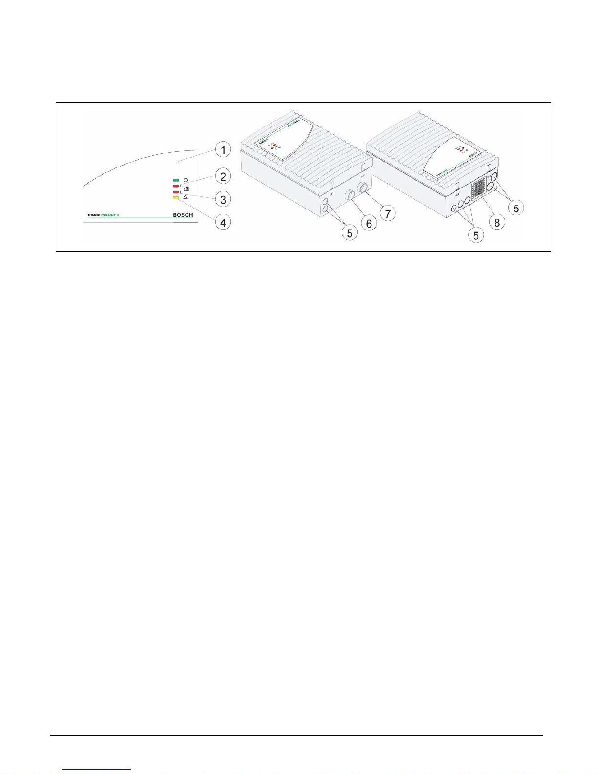
1
Betriebs-LED
1
Operation LED
1
LED « en service »
2
Alarm-LED für Detektormodul 2
2
Alarm LED for detector module 2
2
LED d’alarme pour cellule de détection 2
3
Alarm-LED für Detektormodul 1
3
Alarm LED for detector module 1
3
LED d’alarme pour cellule de détection 1
4
LED Sammelstörung
4
Collective fault LED
4
LED de dérangement collectif
5
Vorgestanzte Kabeleinführungen zum
Anschluss an BMZ oder Stromversorgung (Ein-/Ausgang)
5
Pre-punched cable entries for connection to fire panel or power supply (input/output)
5
Entrées de câbles prédécoupées pour la
connexion au tableau de signalisation
ou à l’alimentation (entrée/sortie)
6
Anschluss Rohrsystem 1
6
Connection pipe system 1
6
Raccordement canalisation 1
7
Anschluss Rohrsystem 2
7
Connection pipe system 2
7
Raccordement canalisation 2
8
Anschluss für Luftrückführung
8
Connection for air-return pipe
8
Connexion pour retour d’air
Bosch Sicherheitssysteme GmbH - 2 - F.01U.045.264 | de/en/fr | A6 | 2007.03
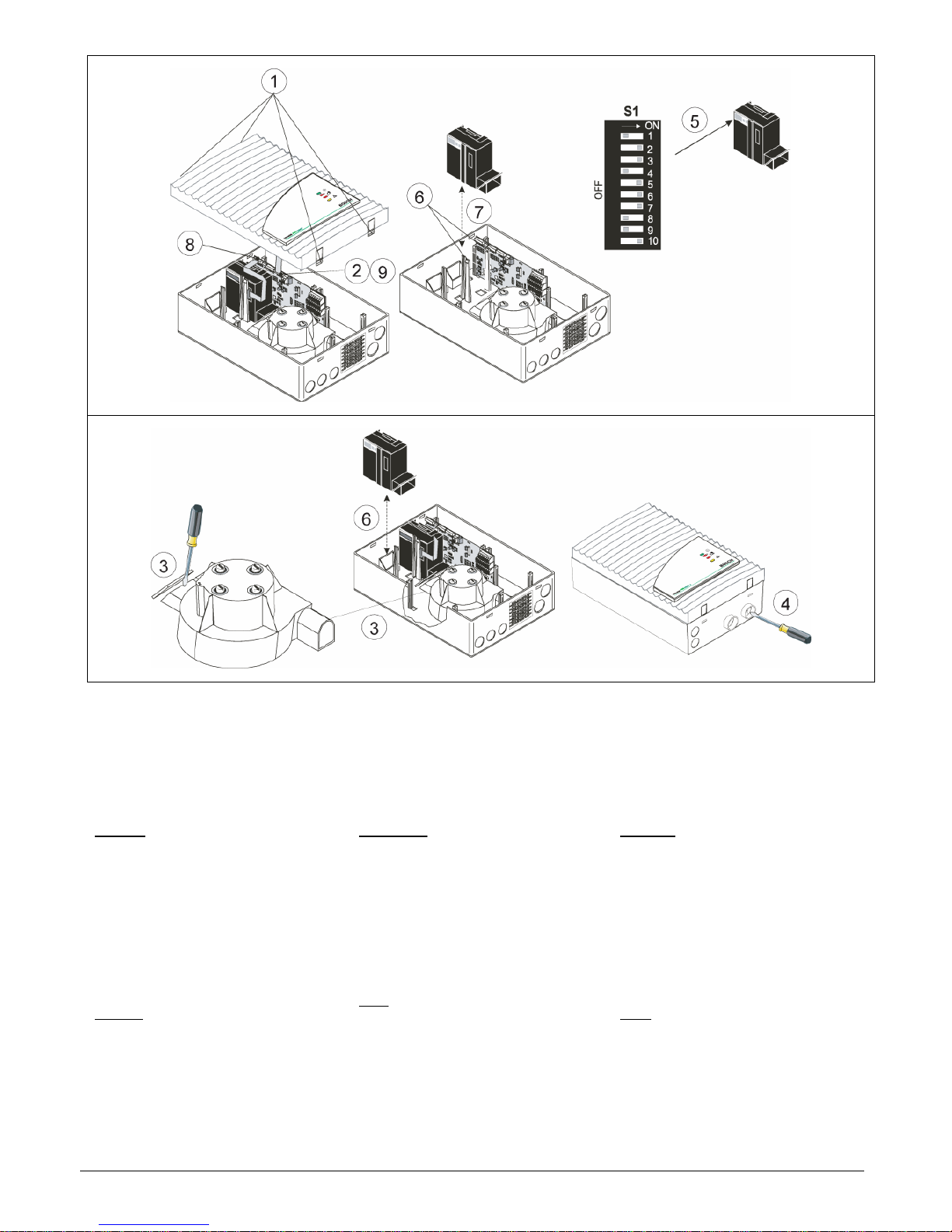
Einbau Detektormodul Installation of the Detector Module Mise en place de la cellule de dé-
tection
Führen Sie alle nachfolgenden Arbeiten im
spannungslosen Zustand des Gerätes aus.
Detektormodule nicht unter Spannung anoder abstecken!
Make sure the device is powered down
before you perform the following steps.
Don’t plug or unplug detector modules
while device is power supplied!
N’effectuez les travaux suivants que quand
l’appareil est débranché.
Ne pas connecter ou déconnecter cellules
de détection quand l’appareil est alimentée.
Achtung:
Es dürfen nur die Detektormodule des Typs
DM-TP-80, DM-TP-25 und DM-TP-05 mit der
VdS-Zertifizierung (Anerkennungsnummer
G 204082) eingesetzt werden.
1. Öffnen Sie das Gerät durch vorsichtiges
Entriegeln der Gehäuse-Schnellverschlüsse
und heben Sie den Gehäusedeckel etwas
ab.
2. Ziehen Sie das Anschlusskabel der Anzeigeplatine vorsichtig von der Grundplatine ab
und entfernen Sie den Gehäusedeckel.
Hinweis:
Soll das Gerät lediglich mit einem Detektormodul bestückt werden (TITANUS PRO·SENS
®
TP-1 A), so gehen Sie weiter zu Punkt 5. Zur
Bestückung mit zwei Modulen für das TITANUS
PRO·SENS
®
TP-2 A folgen Sie den weiteren
Anweisungen.
Please note:
Only detector modules specified as DM-TP-80,
DM-TP-25 or DM-TP-05 and approved by the
VdS Certification Authority (approval number
G 204082) may be used.
1. Open the device by carefully unlocking the
housing quick locks. Then slightly lift the
housing lid.
2. Carefully unplug the connection cable of the
display board out of the base board and remove the housing lid.
Note:
If the device will be provided with only one
detector module (TITANUS PRO·SENS
®
TP-1 A), please skip to point 5. In case of the
TITANUS PRO·SENS
®
TP-2 A with two modules, please go on as explained in the following.
Attention:
Seulement les cellules de détection du type
DM-TP-80, DM-TP-25 et DM-TP-05 qui sont
reconnues par la certification du VdS avec le
numéro d'acceptation G 204082 peuvent être
utilisées.
1. Ouvrez l’appareil en enfonçant légèrement
les pattes de fermeture rapide. Ensuite, soulevez un peu le couvercle.
2. Déconnectez le câble d’affichage avec
précaution de la carte principale et retirez le
couvercle.
N. B.:
Si vous n'utilisez qu'une seule cellule de détection (TITANUS PRO·SENS
®
TP-1 A), allez à
l'étape 5. Pour le TITANUS PRO·SENS
®
TP-2 A avec deux cellules de détections, suivez les instructions ci-dessous.

Bosch Sicherheitssysteme GmbH - 3 - F.01U.045.264 | de/en/fr | A6 | 2007.03
3. Für den Einbau des zweiten Detektormoduls
wurde die Lüfterabdeckung für den zweiten
Ansaugkanal ab Werk bereits entfernt.
4. Außerdem ist der Anschluss des zweiten
Rohrsystems (gekennzeichnet durch “II“) ab
Werk vorbereitet.
5. Die Einstellungen am Detektormodul (Kontakte des Schalters S1) sind ab Werk erfolgt.
Weitere Informationen siehe auch “Einstellungen des Detektormoduls“.
6. Spreizen Sie die zur Fixierung des Detektormoduls vorgesehenen Halteklammern an
der entsprechenden Montageposition etwas
auseinander.
7. Setzen Sie das Detektormodul vorsichtig ein,
bis es hörbar einrastet und somit durch die
Halteklammern fixiert wird.
Hinweis:
Vergewissern Sie sich, dass das eingesetzte Detektormodul fest und sicher durch die
Halteklammern fixiert wird, indem Sie die
Halteklammern zusätzlich etwas von Hand
zusammendrücken.
8. Verbinden Sie das Detektormodul durch das
Flachbandkabel mit der Grundplatine. Achten Sie hierbei auf die Anschlüsse und Beschriftungen der Grundplatine.
9. Schließen Sie die Anzeigeplatine wieder an
die Grundplatine an. Achten Sie hierbei ebenfalls auf die Anschlüsse und Beschriftungen der Grundplatine.
3. For installing the second detector module,
the fan cover of the second suction pipe has
been removed ex factory.
4. Additionally, the connection for the second
pipe system, marked by “II”, is prepared ex
factory.
5. The required settings at the detector module
(by setting the contacts of switch S1) have
been made ex factory. For further information see also “Detector module settings”.
6. Carefully spread the brackets a little. They
are used to fix the detector module in the
corresponding mounting position.
7. Carefully place the detector module between
the brackets until it audibly snaps and thus,
is fixed by the support clamps.
Note:
Press the brackets additionally by hand to
make sure that the inserted detector module is tightly and safely fixed by the brackets.
8. Connect the detector module to the base
board via the ribbon cable. Note the connections and labeling of the base board.
9. Reconnect the display board to the base
board. Note the connections and labeling of
the base board.
3. Pour l’installation de la seconde cellule de
détection, la couverture de ventilateur de la
deuxième pipe de succion a été enlevée ex
usine .
4. En outre, le raccordement de la deuxième
canalisation (caractérisé par "II") est préparée départ usine.
5. Les réglages nécessaires à la cellule de
détection (en réglant le commutateur S1)
sont éffectués ex usine. Pour des renseignements supplémentaires cf. aussi « Réglages de la cellule de détection »).
6. Ecartez un peu les guides de fixation de la
cellule de détection à la position correspondante.
7. Insérez la cellule de détection jusqu’au clic
qui indique une bonne fixation.
N. B.:
Vérifiez que la cellule est bien insérée et
bien maintenue par les guides de fixation
en les serrant un peu à la main.
8. Connectez le câble plat de la cellule de
détection à la carte principale. Faites attention à la numérotation des connecteurs sur
la carte principale.
9. Reconnectez l’affichage à la carte principale. Faites attention au marquage des
connecteurs sur la carte principale.
Bosch Sicherheitssysteme GmbH - 4 - F.01U.045.264 | de/en/fr | A6 | 2007.03
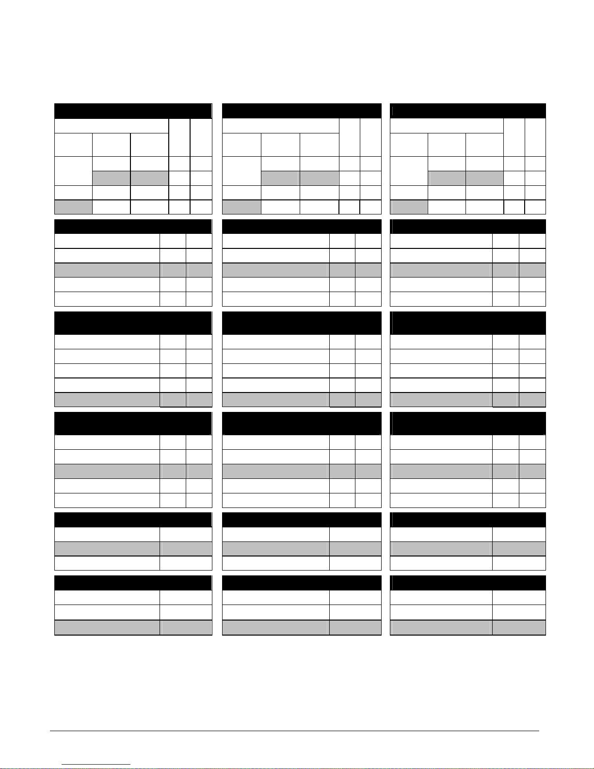
Einstellungen des Detektormoduls Detector Module Settings Réglages de la cellule de détection
Die ab Werk erfolgten Standardeinstellungen
des Schalters S1 sind jeweils grau hinterlegt.
on = ein
off = aus
The standard settings of the S1 switch carried out
ex factory have a grey background.
on
off
Les réglages standard du DIP-switch S1
accomplies départ usine sont représentés sur
fond gris.
on = ouvert
off = fermé
Einstellung der Ansprechsensibilität
Setting the response sensitivity
Réglage de la sensibilité de response
Detektormodul (DM) Detector module (DM) Cellule de détection (DM)
DM-TP-
80
DM-TP-
25
DM-TP-
05
S1.1 S1.2
DM-TP-
80
DM-TP-
25
DM-TP-
05
S1.1 S1.2
DM-TP-
80
DM-TP-
25
DM-TP-
05
S1.1 S1.2
2 %/m 0,4 %/m on on 2 %/m 0,4 %/m on on 2 %/m 0,4 %/m on on
nicht
möglich
1 %/m 0,2 %/m off on
not possi-
ble
1 %/m 0,2 %/m off on
ne pas
utiliser
1 %/m 0,2 %/m off on
1,6 %/m 0,5 %/m 0,1 %/m on off 1,6 %/m 0,5 %/m 0,1 %/m on off 1,6 %/m 0,5 %/m 0,1 %/m on off
0,8 %/m 0,25 %/m 0,05 %/m off off 0,8 %/m 0,25 %/m 0,05 %/m off off 0,8 %/m 0,25 %/m 0,05 %/m off off
Einstellung der Alarmverzögerung
Setting the alarm delay
Réglage de la temporisation d’alarme
S1.3 S1.4
S1.3 S1.4
S1.3 S1.4
0 Sekunden off off 0 seconds off off 0 secondes off off
10 Sekunden on off 10 seconds on off 10 secondes on off
30 Sekunden off on 30 seconds off on 30 secondes off on
60 Sekunden on on 60 seconds on on 60 secondes on on
Einstellung der Auslöseschwelle
“Luftstromstörung“
Setting the activating threshold
“air flow fault”
Réglage du seuil
« dérangement débit d’air »
S1.5 S1.6
S1.5 S1.6
S1.5 S1.6
I on off I on off I on off
II off on II off on II off on
III off off III off off III off off
IV on on IV on on IV on on
Einstellung der Verzögerung
“Luftstromstörung“
Setting the delay
“air flow fault“
Réglage de la temporisation
« dérangement débit d’air »
S1.7 S1.8
S1.7 S1.8
S1.7 S1.8
0,5 Minuten off on 0,5 minutes off on 0,5 minutes off on
2 Minuten on off 2 minutes on off 2 minutes on off
15 Minuten on on 15 minutes on on 15 minutes on on
60 Minuten off off 60 minutes off off 60 minutes off off
Einstellung der Störungsspeicherung
Setting the fault signal
Automaintien du dérangement
S1.9
S1.9
S1.9
nicht speichernd off non-latched off sans automaintien off
speichernd on latched on avec automaintien on
Einstellung LOGIC⋅SENS
Setting LOGIC⋅SENS
Réglage LOGIC⋅SENS
S1.10
S1.10
S1.10
aus off off off
sans LOGIC
⋅
SENS
off
ein on on on
avec LOGIC⋅SENS
on
 Loading...