

Bosch TA Installation And Maintenance Manual
Installation and Maintenance Manual
TA Series
6 720 220 046
Revised 05-12

©Copyright 2012 Bosch, Inc All rights reserved
Table of Contents
TABLE OF CONTENTS
Model Nomenclature ......................................................3
Initial Inspection ............................................................4
General Description .......................................................4
Moving And Storage .......................................................4
Safety Considerations ....................................................4
Location .........................................................................4
Installation .....................................................................4
Mounting Vertical Units ..................................................4
Mounting Horizontal Units .............................................5
Condensate Drain ..........................................................5
Duct System ...................................................................6
Piping .............................................................................6
Electrical ........................................................................6
Ecm Interface Board Thermostat Connections .............7
Safety Devices And The UPM Controller ........................9
Sequence Of Operation ...............................................12
Electric Heater Package Option ...................................12
Sequence Of Operation Two Stage Units .....................13
Cooling Mode ..............................................................13
TA Series
3
Heating Mode ..............................................................13
Well Water Systems ......................................................13
Installation Of Pressure Regulating Valves ...................13
Cooling Tower/Boiler Systems .....................................14
Earth Coupled Systems ...............................................14
System Checkout .........................................................14
Unit Start-Up ................................................................14
Heat Recovery Package ...............................................15
Typical Connection Piping ...........................................15
Water Tank Preparation: ...............................................15
HR Water Piping: ..........................................................16
Water Tank Rell: .........................................................16
Initial Start-Up: ............................................................16
Maintenance ................................................................17
Typical Wiring Diagrams ...............................................21
Operating Pressures & Temperatures ..........................23
Unit Check-Out Sheet ..................................................27
Troubleshooting ...........................................................28
MODEL NOMENCLATURE
TA 049 - 1 VT C - F L T
SERIES:
TA
NOMINAL CAPACITY:
VOLTAGE DESIGNATIONS:
1 - 208/1/60 & 230/1/60
CABINET CONFIGURATION:
VT - VERTICAL
HZ - HORIZONTAL
CF - COUNTERFLOW
HEAT EXCHANGER MATERIAL:
C - COPPER
N - CUPRO-NICKEL
Revised 05-12
SUPPLY AIR LOCATION:
T - TOP (VT ONLY)
E - END BLOW (HZ ONLY)
B - BOTTOM (CF ONLY)
RETURN AIR LOCATION:
S - STRAIGHT THRU
(HZ ONLY)
L - LEFT
R - RIGHT
WATER CONNECTION
LOCATION:
F-FRONT
6 720 220 046
4 TA Series
Initial Inspection
INITIAL INSPECTION
Be certain to inspect all cartons or crates on each unit
as received at the job site before signing the freight
bill. Verify that all items have been received and that
there are no visible damages; note any shortages or
damages on all copies of the freight bill. In the event
of damage or shortage, remember that the purchaser
is responsible for ling the necessary claims with the
carrier. Concealed damages not discovered until after
removing the units from the packaging must be
reported to the carrier within 24 hours of receipt.
GENERAL DESCRIPTION
These Water-to-Air Heat Pumps provide the best
combination of performance and ef ciency
available. Safety devices are built into each unit to
provide the maximum system protection possible
when properly installed and maintained.
The TA Water-to-Air Heat Pumps are Underwriters
Laboratories (UL) and (cUL) listed for safety. The
water-to-Air Heat Pumps are designed to operate
with entering uid temperature between 20°F to
80°F in the heating mode and between 50°F to
110°F in the cooling mode.
50°F Min. EWT for well water applications with
suffi cient water fl ow to prevent freezing.
Antifreeze solution is required for all closed
loop applications. Cooling Tower/Boiler and
Earth Coupled (Geo Thermal) applications
should have suffi cient antifreeze solution to
protect against extreme conditions and
equipment failure. Frozen water coils are not
covered under warranty.
This product should not be used for
temporarily heating/cooling during
construction. Doing so may effect the units
warranty.
less than 6 tons, no more than three high. “Do not
stack units larger than 6 tons.”
SAFETY CONSIDERATIONS
Installation and servicing of this equipment can be
hazardous due to system pressure and electrical
components. Only trained and quali ed personnel
should install, repair, or service the equipment.
Untrained personnel can perform basic functions of
maintenance such as cleaning coils and replacing
lters.
Before performing service or maintenance
operations on the system, turn off main power
to the unit. Electrical shock could cause
personal injury or death.
When working on equipment, always observe
precautions described in the literature, tags, and
labels attached to the unit. Follow all safety codes.
Wear safety glasses and work gloves. Use a
quenching cloth for brazing, and place a re
extinguisher close to the work area.
LOCATION
Locate the unit in an indoor area that allows easy
removal of the lter and access panels, and has
enough room for service personnel to perform
maintenance or repair. Provide suf cient room to
make uid, electrical, and duct connection(s). If the
unit is located in a con ned space such as a closet,
provisions must be made for return air to freely enter
the space. On horizontal units, allow adequate room
below the unit for a condensate drain trap and do
not locate the unit above supply piping. These units
are not approved for outdoor installation; therefore,
they must be installed inside the structure being
conditioned. Do not locate in areas that are subject
to freezing.
MOVING AND STORAGE
If the equipment is not needed for immediate
installation upon its arrival at the job site, it should
be left in its shipping carton and stored in a clean,
dry area. Units must only be stored or moved in the
normal upright position as indicated by the “UP”
arrows on each carton at all times. If unit stacking is
required, stack units as follows: Vertical units less
than 6 tons, no more than two high. Horizontal units
6 720 220 046
INSTALLATION
Remove all shipping blocks under blower
housing. Loosen compressor mounting bolts.
MOUNTING VERTICAL UNITS
Vertical units up to six tons are available in left or
right air return con gurations. Vertical units should
be mounted level on a vibration absorbing pad
Subject to change without prior notice Revised 05-12
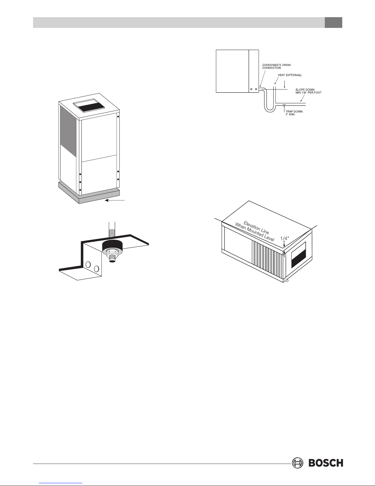
Mounting Horizontal Units
slightly larger than the base to minimize vibration
transmission to the building structure. It is not
necessary to anchor the unit to the oor.
(See Figure #1).
MOUNTING HORIZONTAL UNITS
VIBRATION
PAD
FULL SIZE
Figure #1
TA Series
Figure #3
5
pan is usually placed on a plywood base isolated
from the ceiling joists by additional layers of
vibration absorbing mesh. In both cases, a 3/4”
drain connected to this secondary pan should be
run to an eave at a location that will be noticeable.
If the unit is located in a crawl space, the bottom of
the unit must be at least 4” above grade to prevent
ooding of the electrical parts due to heavy rains.
Figure #2
While horizontal units may be installed on any level
surface strong enough to hold their weight, they are
typically suspended above a ceiling by threaded rods.
The rods are usually attached to the unit corners by
hanger bracket kits. (See Figure #2). The rods must be
securely anchored to the ceiling. Refer to the hanging
bracket assembly and installation instructions for
details. Horizontal units installed above the ceiling
must conform to all local codes. An auxiliary drain pan
if required by code, should be at least four inches
larger than the bottom of the heat pump. Plumbing
connected to the heat pump must not come in direct
contact with joists, trusses, walls, etc.
Some applications require an attic oor installation
of the horizontal unit. In this case the unit should
be set in a full size secondary drain pan on top of a
vibration absorbing mesh. The secondary drain pan
prevents possible condensate overow or water
leakage damage to the ceiling. The secondary drain
Figure #4
CONDENSATE DRAIN
A drain line must be connected to the heat pump
and pitched away from the unit a minimum of 1/8”
per foot to allow the condensate to ow away from
the unit.
This connection must be in conformance with local
plumbing codes. A trap must be installed in the
condensate line to insure free condensate ow.
(Heat Pumps are not internally trapped). A vertical
air vent is sometimes required to avoid air pockets.
(See Figure #3). The length of the trap depends on
the amount of positive or negative pressure on the
drain pan. A second trap must not be included.
The horizontal unit should be pitched
approximately 1/4” towards the drain in both
directions, to facilitate condensate removal. (See
Figure #4)
Revised 05-12
6 720 220 046

Duct System
6 TA Series
unit.
TA
DUCT SYSTEM
A supply air outlet collar and return air duct ange
are provided on all units to facilitate duct
connections. Refer to the Bosch individual data
specication sheet for physical dimensions of the
collar and ange.
A exible connector is recommended for supply and
return air duct connections on metal duct systems. All
metal ducting should be insulated with a minimum of
one inch duct insulation to avoid heat loss or gain and
prevent condensate forming during the cooling
operation. Application of the unit to uninsulated duct
work is not recommended as the unit’s performance
will be adversely affected. Do not connect discharge
ducts directly to the blower outlet. The factory
provided air lter must be removed when using a lter
back return air grill. The factory lter should be left in
place on a free return system.
If the unit will be installed in a new installation
which includes new duct work, the installation
should be designed using current ASHRAE
procedures for duct sizing. If the unit is to be
connected to existing ductwork, a check should be
made to assure that the duct system has the
capacity to handle the air required for the unit
application. If the duct system is too small, larger
ductwork should be installed. Check for existing
leaks and repair.
The duct system and all diffusers should be sized to
handle the designed air ow quietly. To maximize
sound attenuation of the unit blower, the supply
and return air plenums should be insulated. There
should be no direct straight air path thru the return
air grille into the heat pump. The return air inlet to
the heat pump must have at least one 90 degree
turn away from the space return air grille. If air
noise or excessive air ow are a problem, the
blower speed can be changed to a lower speed to
reduce air ow. (Refer to ECM motor interface
board section in this manual and Figure #7)
PIPING
Supply and return piping must be as large as the
unit connections on the heat pump (larger on long
runs). Never use exible hoses of a smaller inside
diameter than that of the uid connections on the
optional cupro-nickel condenser. Copper is
adequate for ground water that is not high in
mineral content. Should your well driller express
concern regarding the quality of the well water
available or should any known hazards exist in your
area, we recommend proper testing to assure the
well water quality is suitable for use with water
source equipment. In conditions anticipating
moderate scale formation or in brackish water a
cupro-nickel heat exchanger is recommended.
Both the supply and discharge water lines will
sweat if subjected to low water temperature. These
lines should be insulated to prevent damage from
condensation.
All manual ow valves used in the system must be
ball valves. Globe and gate valves must not be used
due to high pressure drop and poor throttling
characteristics. Never exceed the recommended
water ow rates as serious damage or erosion of
the water to refrigerant heat exchanger could
occur.
Always check carefully for water leaks and repair
appropriately. Units are equipped with female pipe
thread ttings. Consult the specication sheets for
sizes. Teon tape sealer should be used when
connecting water piping connections to the units to
insure against leaks and possible heat exchanger
fouling. Do not overtighten the connections.
Flexible hoses should be used between the unit and
the rigid system to avoid possible vibration. Ball
valves should be installed in the supply and return
lines for unit isolation and unit water ow
balancing.
ELECTRICAL
(Refer to electrical component box layout, Figure #5)
Field wiring must comply with local and national
electric codes. Power to the unit must be within the
operating voltage range indicated on the unit
nameplate or on the performance data sheet. On
three phase units (single stage units only) phases
must be balanced within 2%.
units are supplied with either a copper or
Operation of unit on improper line voltage or with
excessive phase imbalance will be hazardous to the
unit, constitutes abuse and may void the warranty.
6 720 220 046
Subject to change without prior notice Revised 05-12
ECM Interface Board
Properly sized fuses or HACR circuit breakers must
be installed for branch circuit protection. See unit
nameplate for maximum fuse or breaker size.
The unit is provided with a concentric knock-out in
the front left corner post for attaching common
trade sizes of conduit, route power supply wiring
through this opening. Always connect the ground
lead to the grounding lug provided in the control box
and power leads to the power supply terminal block
as indicated on the wiring diagram and Figure #5.
TA Series
7
Units supplied with internal electric heat
require two (2) separate power supplies: one
for the unit compressor and one for the electric
heater elements, blower motor and control
circuit. Refer to the ELECTRIC HEATER
PACKAGE OPTION section and Figure #8 for
wiring instructions, minimum circuit ampacities
and maximum fuse/breaker sizing.
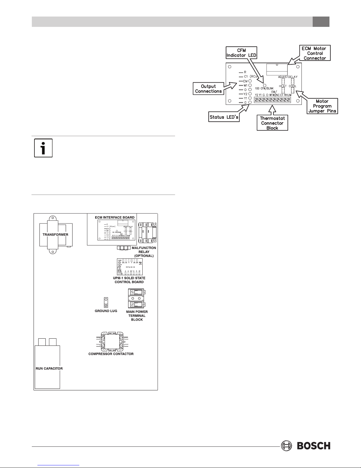
Figure #6 ECM Interface Board
ECM INTERFACE BOARD
THERMOSTAT CONNECTIONS
Thermostat wiring is connected to the 10 pin screw type
terminal block on the lower center portion of the ECM
Interface Board. In addition to providing a connecting
point for thermostat wiring, the interface board also
translates thermostat inputs into control commands for
the variable speed programmable ECM DC fan motor and
displays an LED indication of operating status. The
thermostat connections and their functions are as
follows:
Y2 Second Stage Compressor Operation
Y1 First Stage Compressor Operation
G Fan
O Reversing Valve (energized in cooling)
W1 Auxiliary Electric Heat (runs in
conjunction with compressor)
SINGLE & TWO STEP
Figure #5 - Electrical Box Component Layout
Revised 05-12
EM/W2 Emergency Heat (electric heat only)
NC Transformer 24 VAC Common (extra
connection)
C1 Transformer 24 VAC Common (primary
connection)
R Transformer 24 VAC Hot
HUM Dehumidi cation Mode
If the unit is being connected to a thermostat with a
malfunction light, this connection is made at the
unit malfunction output or relay.
6 720 220 046
8 TA Series
Thermostat Connections
If the thermostat is provided with a malfunction
light powered off of the common (C) side of the
transformer, a jumper between “R” and “COM”
terminal of “ALR” contacts must be made.
If the thermostat is provided with a malfunction
light powered off of the hot (R) side of the
transformer, then the thermostat malfunction
light connection should be connected directly
to the (ALR) contact on the unit’s UPM board.
To the left of the thermostat connection block are a
row of 2 red and 4 green LED’s. These LED’s indicate
the operating status of the unit. They are labeled as
follows:
EM (red) Emergency Heat On
W1 (red) Auxiliary Heat On
O (green) Reversing Valve Energized, unit is in
cooling mode
Y2 (green) Second Stage Compressor On
Y1 (green) First Stage Compressor On
G (green) Fan On
Just above the connector block is a single red LED
labeled CFM that will blink intermittently when the
unit is running and may icker when the unit is off.
This LED indicates the air delivery of the blower at
any given time. Each blink of the LED represent 100
CFM of air delivery so if the LED blinks 12 times,
pauses, blinks 12 times, etc. the blower is delivering
1200 CFM. Refer to Figure #7 for factory
programmed air delivery settings for the TA Series.
To the right of the thermostat connection block is a
green LED labeled dehumidify.
Just above and to the right of the thermostat
connection block are four sets of jumper pins labeled
ADJ, DELAY, HEAT and COOL. The ADJ set of pins are
labeled NORM, (+), (-) and TEST. TA units will all be set
on the NORM position from the factory, however,
air ow can be increased (+) or decreased (-) by 15%
from the pre-programmed setting by relocating the
jumper in this section. The TEST position is used to
verify proper motor operation. If a motor problem is
suspected, move the ADJ jumper to the TEST position
and energize G on the thermostat connection block. If
the motor ramps up to 100% power, then the motor
itself is functioning normally. Always remember to
replace the jumper to NORM, (+) or (-) after testing and
reset the unit thermostat to restore normal operation.
Do not set the ADJ jumper to the (-) setting
when electric heaters are installed. Doing so
may cause the heaters to cycle on their
thermal overload switches, potentially
shortening the life of the switches.
The other three sets of jumper pins are used to
select the proper program in the ECM motor for the
unit. Refer to Figure #7 for the proper jumper
placement.
Always disconnect power before changing
jumper positions on the interface board and
reset the unit afterward.
To the left of the red and green status LED’s is a row
of 1/4” male quick connects. These are used to pass
thermostat inputs on to the rest of the control
circuit. Remember to always turn off unit power at
the circuit breaker before attaching or disconnecting
any wiring from these connections to avoid
accidental short circuits that can damage unit
control components.
Figure 7: Motor Profi le Air Flow Table CFM
Two Stage Units
Model Fan
Only
TA025 600 750 950 950 950 1090 800 A
TA035 900 1000 1200 1200 1200 1400 1000 A
TA049 1200 1300 1700 1700 1700 1950 1450 B
TA061 1300 1500 2000 2000 2000 2100 1900 A
TA071 1300 1500 2100 2100 2100 2300 1900 A
Y1
COOL/
HEAT
6 720 220 046
Y2
COOL/
HEAT
AUX
HEAT
Subject to change without prior notice Revised 05-12
EMERG
HEAT
PLUS
ADJ
MINUS
ADJ
TAP COOL/
HEAT/DELAY
Safety Devices and the UPM Controller
SAFETY DEVICES AND THE
UPM CONTROLLER
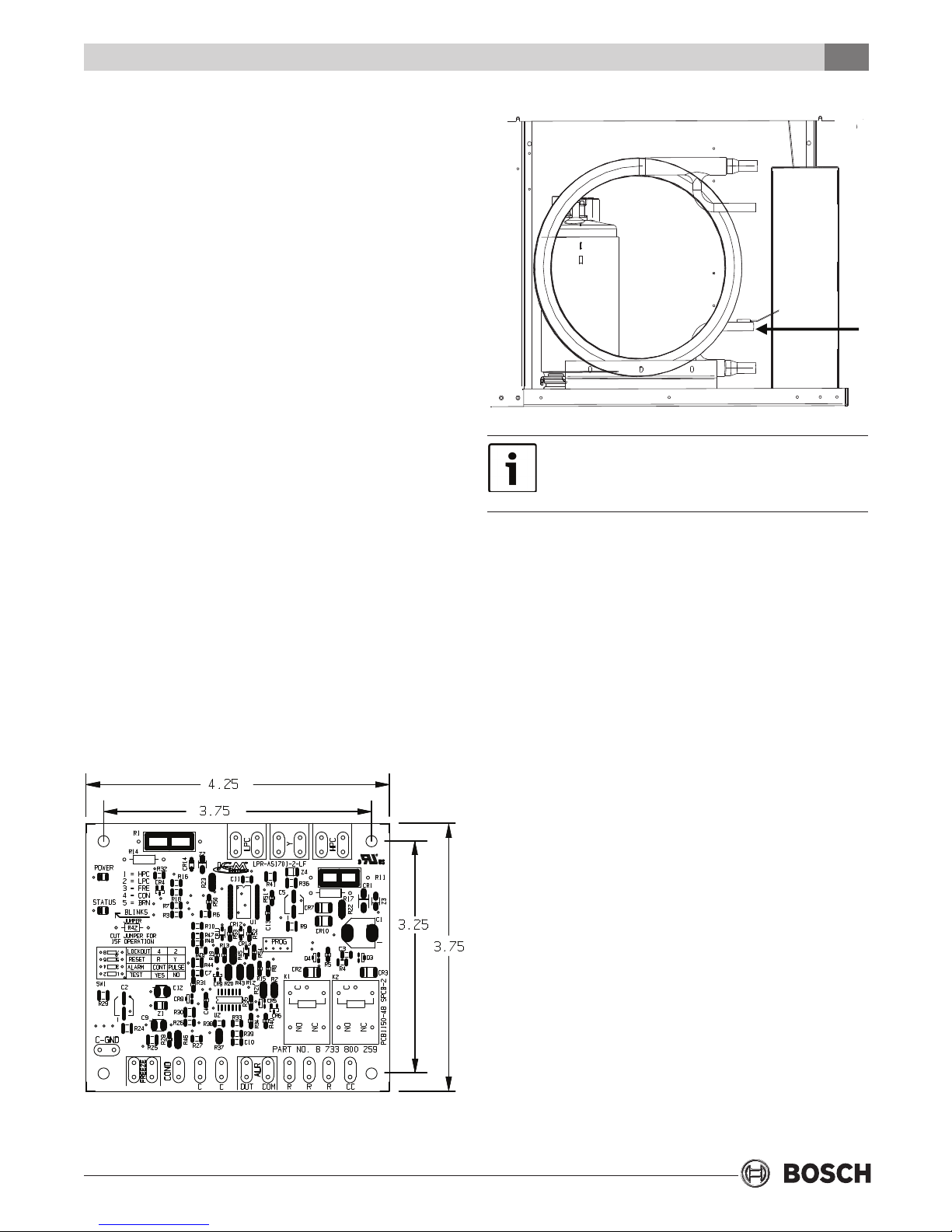
Each unit is factory provided with a Unit Protection
Module (UPM) that controls the compressor operation and monitors the safety controls that protect
the unit.
Safety controls include the following:
TA Series
9
• High pressure switch located in the refrigerant
discharge line and wired across the HPC terminals
on the UPM
• Low pressure switch located in the unit refrigerant
suction line and wired across terminals LPC1 and
LPC2 on the UPM.
• Optional freeze protection sensor, mounted close
to condensing water coil, monitors refrigerant
temperature between condensing water coil and
thermal expansion valve. If temperature drops
below or remains at freeze limit trip for 30
seconds, the controller will shut down the
compressor and enter into a soft lockout
condition. The default freeze limit trip is 30°F,
however this can be changed to 15°F by cutting
the R42 resistor located on top of DIP switch SW1.
• The optional condensate over ow protection
sensor (standard on horizontal units) is located in
the drain pan of the unit and connected to the
‘COND’ terminal on the UPM board.
Freeze
Protection
Sensor
If freeze protection sensor is not installed, a
jumper between freeze contacts must be installed
on the UPM board otherwise unit will not start.
The UPM includes the following features:
• ANTI-SHORT CYCLE TIME—5 minute delay on
break timer to prevent compressor short cycling.
• RANDOM START—Each controller has a unique
random start delay ranging from 270 to 300 seconds to
reduce the chances of multiple units simultaneously
starting after initial power up or after a power
interruption, creating a large electrical spike.
• LOW PRESSURE BYPASS TIMER—If the compressor is
running and the low pressure switch opens, then the
control will keep the compressor on for 120 seconds.
After 2 minutes if the low pressure switch remains
open, the control will shut down the compressor and
enter a soft lockout. The compressor will not be
energized until the low pressure switch closes and the
anti-short cycle time delay expires. If the low pressure
switch opens 2–4 times in 1 hour, the unit will enter a
hard lock out and need to be reset.
Revised 05-12
• BROWNOUT/SURGE/POWER INTERRUPTION
PROTECTION—The brownout protection in the UPM
board will shut down the compressor if the
incoming power falls below 18 VAC. The compressor
will remain off till the voltage goes above 18 VAC and
the anti short cycle timer (300 seconds) times out.
The unit will not go into a hard lockout.
6 720 220 046
10 TA Series
Safety Devices and the UPM Controller
• MALFUNCTION OUTPUT—Alarm output is Normally
Open (NO) dry contact. If 24 VAC output is needed
R must be wired to the ALR-COM terminal; 24VAC
will be available on the ALR-OUT terminal when the
unit is in alarm condition. If pulse is selected the
alarm output will be pulsed. The fault output will
depend on the dip switch setting for “ALARM”. If it
set to “CONST’, a constant signal will be produced
to indicate a fault has occurred and the unit
requires inspection to determine the type of fault. If
it is set to “PULSE”, a pulse signal is produced and a
fault code is detected by a remote device indicating
the fault. See L.E.D. Fault Indication below for blink
code explanations. The remote device must have a
malfunction detection capability when the UPM
board is set to “PULSE”.
• TEST DIP SWITCH—A test dip switch is provided to
reduce all time delay settings to 10 seconds during
troubleshooting or veri cation of unit operation.
Note that operation of the unit while in test mode
can lead to accelerated wear and premature failure
of the unit. The “TEST” switch must be set back to
“NO” for normal operation.
- One blink—High pressure lockout
- Two blinks—Low pressure lockout
- Three blinks—Freeze sensor lockout
- Four blinks—Condensate over ow
- Five blinks—Brownout
• INTELLIGENT RESET—If a fault condition is initiated,
the 5 minute delay on break time period is initiated
and the unit will restart after these delays expire.
During this period the fault LED will indicate the
cause of the fault. If the fault condition still exists or
occurs 2 or 4 times (depending on 2 or 4 setting for
Lockout dip switch) before 60 minutes, the unit will
go into a hard lockout and requires a manual lockout
reset. A single condensate over ow fault will cause
the unit to go into a hard lockout immediately, and
will require a manual lockout reset.
• LOCKOUT RESET—A hard lockout can be reset by
turning the unit thermostat off and then back on
when the “RESET” dip switch is set to “Y” or by
shutting off unit power at the circuit breaker when
the “RESET” dip switch is set to “R”.
• FREEZE SENSOR—The freeze sensor input is
active all the time, if a freeze option is not selected
the freeze terminals will need a jumper. There are
2 con gurable freeze points, 30°F & 15°F. The unit
will enter a soft lock out until the temperature
climbs above the set point and the anti-short cycle
time delay has expired. The freeze sensor will shut
the compressor output down after 90 seconds of
water ow loss and report a freeze condition. It is
recommended to have a ow switch to prevent the
unit from running if water ow is lost.
If unit is employing a fresh water system (no
anti-freeze protection), it is extremely important to
have the “Freeze” jumper R42 resistor set to 30°F
in order to shut down the unit at the appropriate
leaving water temperature and protect your heat
pump from freezing if a freeze sensor is included.
• L.E.D. FAULT INDICATION—Two L.E.D. indicators
are provided:
• Green: Power L.E.D. indicates 18—30 VAC
present at the board.
• Red: Fault indicator with blink codes as follows:
The blower motor will remain active during a
lockout condition.
• UPM BOARD DEFAULT SETTINGS—Your UPM
board will come from the factory with the
following default settings:
• Freeze—“Terminals not jumped” on all the time
• Tem p—30°F
• Lockout—2
• Reset—“Y”
• Alarm—“PULSE”
• Tes t—“NO”
• Dry Contact—“Normally Open (NO)”
Considerations
1. Always check incoming line voltage power supply
and secondary control voltage for adequacy.
Transformer primaries are dual tapped for 208
and 230 volts. Connect the appropriate tap to
ensure a minimum of 18 volts secondary control
voltage. 24 volts is ideal for best operation.
6 720 220 046
Subject to change without prior notice Revised 05-12
 Loading...