

Bosch T4200 14-2D, T4200 18-2D, T4200 11-2D Installation And User Instructions Manual
Installation and Users Instructions
Gas Instantaneous Water Heater
Therm 4200
T4200 11/14/18-2D
6 720 821 605 (2017/08) ZA

2
Table of contents
Therm 4200 – 6 720 821 605 (2017/08)
Table of contents
1 Key to symbols and safety instructions . . . . . . . 3
1.1 Key to symbols . . . . . . . . . . . . . . . . . . . . . . . . . . . . 3
1.2 Safety information . . . . . . . . . . . . . . . . . . . . . . . . . 3
2 Technical Characteristics and Dimensions . . . . 6
2.1 Type overview . . . . . . . . . . . . . . . . . . . . . . . . . . . . . 6
2.2 Material attached . . . . . . . . . . . . . . . . . . . . . . . . . . 6
2.3 Type plate . . . . . . . . . . . . . . . . . . . . . . . . . . . . . . . . 6
2.4 Description of appliance . . . . . . . . . . . . . . . . . . . . . 6
2.5 Accessory (not supplied with the appliance) . . . . 6
2.6 Dimensions . . . . . . . . . . . . . . . . . . . . . . . . . . . . . . . 7
2.7 Electrical diagram . . . . . . . . . . . . . . . . . . . . . . . . . . 8
2.8 Function . . . . . . . . . . . . . . . . . . . . . . . . . . . . . . . . . . 8
2.9 Technical Data . . . . . . . . . . . . . . . . . . . . . . . . . . . . . 9
3Use . . . . . . . . . . . . . . . . . . . . . . . . . . . . . . . . . . . . . 10
3.1 Digital display - description . . . . . . . . . . . . . . . . . 10
3.2 Batteries . . . . . . . . . . . . . . . . . . . . . . . . . . . . . . . . 10
3.3 Before starting up the heater . . . . . . . . . . . . . . . . 10
3.4 Turning the heater on and off . . . . . . . . . . . . . . . . 10
3.5 Water flow . . . . . . . . . . . . . . . . . . . . . . . . . . . . . . . 11
3.6 Power adjustment . . . . . . . . . . . . . . . . . . . . . . . . . 11
3.7 Temperature/flow adjustment . . . . . . . . . . . . . . . 11
4Regulations . . . . . . . . . . . . . . . . . . . . . . . . . . . . . 11
5 Installation (must be carried out only by
qualified technicians) . . . . . . . . . . . . . . . . . . . . . 12
5.1 Important information . . . . . . . . . . . . . . . . . . . . . 12
5.2 Selection of location for installation . . . . . . . . . . 12
5.3 Fixing the appliance . . . . . . . . . . . . . . . . . . . . . . . 13
5.4 Water connection . . . . . . . . . . . . . . . . . . . . . . . . . 13
5.5 Hydrogenerator operation . . . . . . . . . . . . . . . . . . 14
5.6 Gas connection . . . . . . . . . . . . . . . . . . . . . . . . . . . 14
5.7 Commissioning . . . . . . . . . . . . . . . . . . . . . . . . . . . 14
6 Adjustments (must be carried out only by . . . . . .
qualified technicians) . . . . . . . . . . . . . . . . . . . . . . . . . . . . 15
6.1 Factory regulations . . . . . . . . . . . . . . . . . . . . . . . . 15
6.2 Pressure regulation . . . . . . . . . . . . . . . . . . . . . . . . 15
6.3 Conversion to a different type of gas . . . . . . . . . . 16
7 Maintenance (must be carried out only by . . . . . .
qualified technicians) . . . . . . . . . . . . . . . . . . . . . . . . . . . . 16
7.1 Periodic maintenance tasks . . . . . . . . . . . . . . . . . 16
7.2 Startup after maintenance work . . . . . . . . . . . . . 16
7.3 Heater purge . . . . . . . . . . . . . . . . . . . . . . . . . . . . . 16
7.4 Flue gas safety device . . . . . . . . . . . . . . . . . . . . . . 17
7.5 Safe operation/ risk for prolonged use . . . . . . . . 17
8Problems . . . . . . . . . . . . . . . . . . . . . . . . . . . . . . . 18
8.1 Problem/cause/solution . . . . . . . . . . . . . . . . . . . . 18
9 Environment / disposal . . . . . . . . . . . . . . . . . . . 19
10 Warranty Terms . . . . . . . . . . . . . . . . . . . . . . . . . 19
3
Key to symbols and safety instructions
Therm 4200 – 6 720 821 605 (2017/08)
1 Key to symbols and safety instructions
1.1 Key to symbols
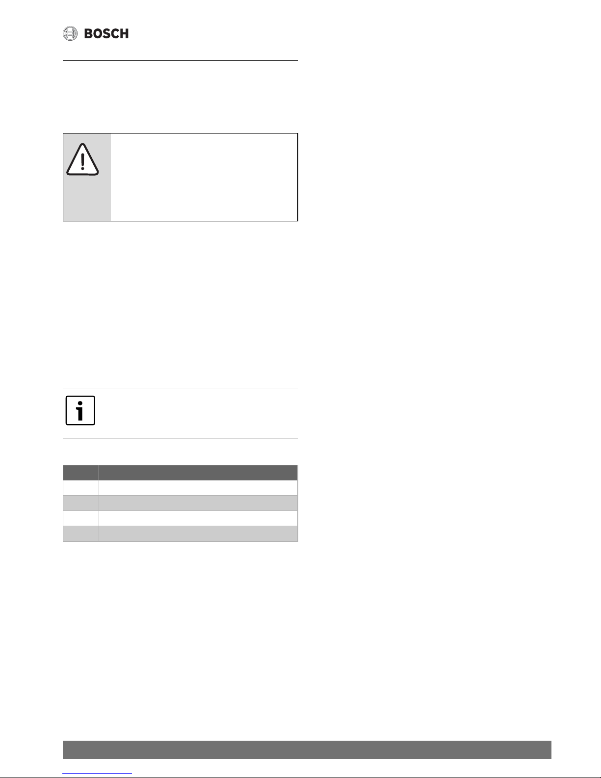
Warnings
Warnings in this document are identified by
a warning triangle printed against a grey
background.
Keywords at the start of a warning indicate
the type and seriousness of the ensuing risk
if measures to prevent the risk are not taken.
The following keywords are defined and can be used in this
do
cument:
• NOTICE indicates a s
ituation that could result in damage to
property or equipment.
• CAUT
ION indicates a situation that could result in minor to
medium injury.
• WARNI
NG indicates a situation that could result in severe
injury or death.
• DA
NGER indicates a situation that will result in severe
injury or death.
Important information
This symbol indicates important information
where there is no risk to people or property.
Additional symbols
Table 1
Symbol Explanation
▶
Step in an action sequence
Cross-reference to another part of the document
•
List entry
– List entry (second level)
1.2 Safety information
Important
▶ Read these instructions for use
carefully so as to familiarize yourself
with the appliance before connecting
it to its gas container.
▶ Keep these instructions for future
reference.
If there is a smell of gas:
▶ Close the gas valve.
▶ Open windows.
▶ Do not connect any electrical
appliance.
▶ Extinguish any naked flames.
▶ Phone the gas company or an
authorized technician from a safe
distance.
If there is a smell of burnt gases:
▶ Disconnect the appliance.
▶ Open doors and windows.
▶ Inform an installation company.
Fitting, modifications
▶ The fitting and modification of the
installation of the appliance must be
carried out only by an authorized
technician.
▶ The installation of the water heater
may only be carried out by a
registered installer and that such
installations shall comply with the
requirements of SANS 10087-1.
▶ The pipes carrying burnt gases must
not be modified.
▶ Do not close or reduce air circulation
holes.

4
Key to symbols and safety instructions
Therm 4200 – 6 720 821 605 (2017/08)
Maintenance
▶ The user must maintain and
periodically service the appliance.
▶ The user is responsible for the safety
and environmental compatibility of
the installation.
▶ The appliance should be serviced
annually.
▶ Only original spare parts should be
used.
Explosive and inflammable materials
▶ Inflammable materials (paper,
solvents, ink, etc.) should not be
stored near the appliance.
Combustion air and ambient air
▶ To avoid corrosion, combustion air
and ambient air should be free of
aggressive substances (for example
halogenated hydrocarbons
containing chlorine and fluoride
composites).
Important information for the user
▶ This appliance may only be installed
by a registered LP Gas installer.
▶ All registered installers are issued
with a card carrying their registration
number.
▶ Ask to be shown the card before
allowing the installation work to
commence and make a note of the
Installer QCC number. Upon
completion of the installation, the
installer is required to explain the
operational details of the appliance
together with the safety instructions.
You will be asked to sign acceptance
of the installation and be provided
with a completion certificate. You
should only sign for acceptance of the
installation when the installation is
completed to your satisfaction.Note
that your invoice is required in the
event that you wish make a guarantee
claim.
Important information for the
installer
▶ This appliance may only be installed
by a LP gas installer registered with
the Liquefied Petroleum Gas
Association of Southern Africa.
▶ The appliance must be installed in
accordance with the requirements of
SANS 10087-1 and any fire
department regulations and/or local
by laws applicable to the area. If in
doubt check with the relevant
authority before undertaking the
installation.
▶ Upon completion of the installation
you are required to fully explain and
demonstrate to the user the
operational details and safety
practices applicable to the appliance
and the installation.
Client information
▶ Inform the client about the function
and operation of the appliance.
▶ Caution clients against performing
modifications or repairs themselves.

5
Key to symbols and safety instructions
Therm 4200 – 6 720 821 605 (2017/08)
Safety of electrical appliances for
domestic use and similar purposes
The following requirements apply in
accordance with EN 60335-1 in order to
prevent hazards from occurring when
using electrical appliances:
“This appliance can be used by children
of 8 years and older, as well as by people
with reduced physical, sensory or
mental capabilities or lacking in
experience and knowledge, if they are
supervised and have been given
instruction in the safe use of the
appliance and understand the resulting
dangers. Children must not play with the
appliance. Cleaning and user
maintenance must not be performed by
children without supervision.”
“If the power cable is damaged, it must
be replaced by the manufacturer, its
customer service department or a
similarly qualified person, so that risks
are avoided.”
6
Technical Characteristics and Dimensions
Therm 4200 – 6 720 821 605 (2017/08)
2 Technical Characteristics and
Dimensions
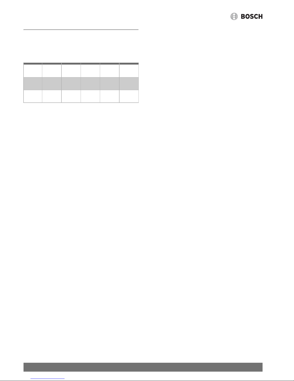
2.1 Type overview
Table 2
T 4200 11 -2 D 23
31
T 4200 14 -2 D 23
31
T 4200 18 -2 D 23
31
[T] Gas instantaneous water heater
[4200] Series
[11] Capacity (l/min)
[-2] Version
[D] Digital display
[23] Appliance set for natural gas
[31] Appliance set for LPG
2.2 Material attached
•Gas water heater
• Fixing elements
• Connections elements
• Documentation
• Two 1.5 V batteries type R
2.3 Type plate
The type plate is located on the left si de o f th e ap pl ian ce, on t he
bottom.
It contains details of the output of
the appliance, the order
number, the approval data and the date of manufacture in
encoded form (FD).
2.4 Description of appliance
Operating convenience, as the heater is ready to operate by
simply pressing a switch.
• Heater for wall-mounting
• Ignition by electronic device triggered when the water valve
op
ens
• Gauge to display temperature, burner operation and
malfu
nctions
• Temperature sensor to monitor the water temperature at
the he
ater output
• Great savings in comparison with conventional heaters,
d
ue to the possibility of power adjustment and no
permanent pilot flame
• Natural gas/LPG burner
• Semi-permanent pilot burner which only functions during
t
he period between the opening of the water valve and the
ignition of the main burner
• Heat exchanger without tin/lead covering
• Water valve in fibreglass-reinforced polyamide, 100%
rec
yclable
• Automatic adjustment of the wa
ter flow by means of a
device which permits a constant flow to be maintained in
spite of variable pressure supplies
• Gas flow adjustment proportional to the water flow to
m
aintain a constant high temperature.
•Safety devices:
– Ionisation probe to check for
accidental extinction of
the burner flame
– Flue gas safety device which tu
rns off the heater in case
of inadequate combusted gas evacuation conditions
– Temperature limiter which preven
ts overheating of the
heat exchanger
2.5 Accessory (not supplied with the appliance)
• Conversion kit from natural gas to butane/propane and
vice-versa.
 Loading...