

Bosch RH328VC-36 Operating/safety Instructions Manual
RH328VC-36
IMPORTANT: IMPORTANT : IMPORTANTE:
Read Before Using Lire avant usage Leer antes de usar
For English Version Version française Versión en español
See page 2 Voir page 14 Ver la página 27
Operating/Safety Instructions
Consignes de fonctionnement/sécurité
Instrucciones de funcionamiento y seguridad
1-877-BOSCH99 (1-877-267-2499) www.boschtools.com
Call Toll Free for
Consumer Information
& Service Locations
Pour obtenir des informations
et les adresses de nos centres
de service après-vente,
appelez ce numéro gratuit
Llame gratis para
obtener información
para el consumidor y
ubicaciones de servicio
2610047991_RH328VC-36 10/4/17 8:38 AM Page 1
-2-
Work area safety
Keep work area clean and well lit. Cluttered or
dark areas invite accidents.
Do not operate power tools in explosive
atmospheres, such as in the presence of
flammable liquids, gases or dust. Power tools
create sparks which may ignite the dust or
fumes.
Keep children and bystanders away while
operating a power tool. Distractions can cause
you to lose control.
Electrical safety
Power tool plugs must match the outlet.
Never modify the plug in any way. Do not use
any adapter plugs with earthed (grounded)
power tools. Unmodified plugs and matching
outlets will reduce risk of electric shock.
Avoid body contact with earthed or grounded
surfaces such as pipes, radiators, ranges
and refrigerators. There is an increased risk of
ele c t ric shock if yo ur body is earthed or
grounded.
Do not expose power tools to rain or wet
conditions. Water entering a power tool will
increase the risk of electric shock.
Do not abuse the cord. Never use the cord
for carrying, pulling or unplugging the power
tool. Keep cord away from heat, oil, sharp
edges or moving parts. Damaged or entangled
cords increase the risk of electric shock.
When operating a power tool outdoors, use
an extension cord suitable for outdoor use.
Use of a cord suitable for outdoor use reduces
the risk of electric shock.
If operating a power tool in a damp location is
unavoidable, use a Ground Fault Circuit
Interrupter (GFCI) protected supply. Use of an
GFCI reduces the risk of electric shock.
Personal safety
Stay alert, watch what you are doing and use
common sense when operating a power tool.
Do not use a power tool while you are tired or
under the influence of drugs, alcohol or
medication. A moment of inattention while
operating power tools may result in serious
personal injury.
Use personal protective equipment. Always
wear eye protection. Protective equipment
such as dust mask, non-skid safety shoes, hard
hat, or hearing protection used for appropriate
General Power Tool Safety Warnings
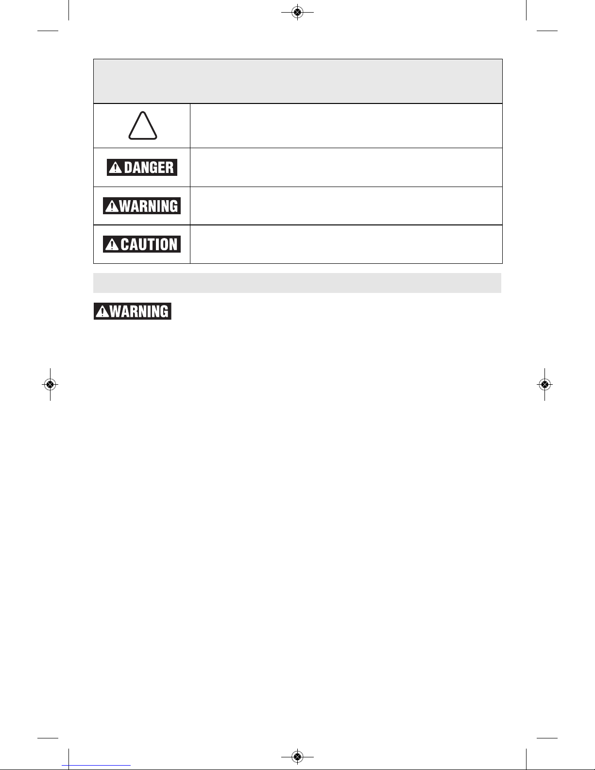
Safety Symbols
The definitions below describe the level of severity for each signal word. Please read the manual
and pay attention to these symbols.
!
This is the safety alert symbol. It is used to alert you to potential
personal injury hazards. Obey all safety messages that follow this
symbol to avoid possible injury or death.
DANGER indicates a hazardous situation which, if not avoided, will
result in death or serious injury.
WARNING indicates a hazardous situation which, if not avoided, could
result in death or serious injury.
CAUTION, used with the safety alert symbol, indicates a hazardous
situation which, if not avoided, will result in minor or moderate injury.
Read all safety warnings and all instructions. Failure to follow the
warnings and instructions may result in electric shock, fire and/or serious
injury.
SAVE ALL WARNINGS AND INSTRUCTIONS FOR FUTURE REFERENCE
The term “power tool” in the warnings refers to your mains-operated (corded) power tool or
battery-operated (cordless) power tool.
2610047991_RH328VC-36 10/4/17 8:38 AM Page 2

-3-
conditions will reduce personal injuries.
Prevent unintentional starting. Ensure the
switch is in the off-position before connecting
to power source and / or battery pack, picking
u
p or carrying the tool. Carrying power tools
with your finger on the switch or energizing power
tools that have the switch on invites accidents.
Remove any adjusting key or wrench before
turning the power tool on. A wrench or a key
left attached to a rotating part of the power tool
may result in personal injury.
Do not overreach. Keep proper footing and
balance at all times. This enables better control
of the power tool in unexpected situations.
Dress properly. Do not wear loose clothing
or jewelry. Keep your hair, clothing and
glo v e s away f r om moving parts. L o o se
clothes, jewelry or long hair can be caught in
moving parts.
If devices are provided for the connection of
dust extraction and collection facilities,
ensure these are connected and properly
used. Use of dust collection can reduce dust-
related hazards.
Power tool use and care
Do not force the power tool. Use the correct
power tool for your application. The correct
power tool will do the job better and safer at the
rate for which it was designed.
Do not use the power tool if the switch does
not turn it on and off. Any power tool that
can n ot be co n trolled w i th the switch is
dangerous and must be repaired.
Disconnect the plug from the power source
and/or the battery pack from the power tool
before making any adjustments, changing
accessories, or storing power tools. Such
preventive safety measures reduce the risk of
starting the power tool accidentally.
Store idle power tools out of the reach of
children and do not allow persons unfamiliar
with the power tool or these instructions to
ope rate the power tool. Powe r tools a re
dangerous in the hands of untrained users.
Maintain power tools. Check for misalignment
o
r binding of moving parts, breakage of parts
and any other condition that may affect the
power tool’s operation. If damaged, have the
pow e r tool rep a ired befo r e use. Man y
accidents are caused by poorly maintained
power tools.
Keep cutting tools sharp and clean. Properly
maintained cutting tools with sharp cutting edges
are less likely to bind and are easier to control.
Use the power tool, accessories and tool
bits etc. in accordance with these instructions,
taking into account the working conditions
and the work to be performed. Use of the
power tool for operations different from those
intended could result in a hazardous situation.
Battery tool use and care
Recharge only with the charger specified by
the manufacturer. A charger that is suitable
for one type of battery pack may create a risk of
fire when used with another battery pack.
Use p o wer tools o n ly with s p e c i fically
designated battery packs. Use of any other
battery packs may create a risk of injury and
fire.
When battery pack is not in use, keep it
away from other metal objects, like paper
clips, coins, keys, nails, screws, or other
small m e t a l ob j e c t s that c a n ma k e a
connection from one terminal to another.
Shorting the battery terminals together may
cause burns or a fire.
Under abusive conditions, liquid may be
ejected from the battery, avoid contact. If
co ntact accidentall y occurs, f lush with
water. If liquid contacts eyes, additionally
seek medical help. Liquid ejected from the
battery may cause irritation or burns.
Service
Have your power tool serviced by a qualified
rep a i r per s o n usi n g only identi c a l
replacement parts. This will ensure that the
safety of the power tool is maintained.
Safety Rules for Cordless Hammer Drills
Wear ear protectors when impact drilling.
Exposure to noise can cause hearing loss.
Use auxiliary handle(s), if supplied with the
tool. Loss of control can cause personal injury.
Hol d power tool by insu lated gri pping
surfaces, when performing an operation
where the cutting accessory may contact
hidden wiring. Cutting accessory contacting a
"live" wire may make exposed metal parts of the
power tool "live" and could give the operator an
electric shock.
Us e c lamps or another p ract ical way to
secure and support the workpiece to a stable
platform. Holding the work by hand or against
2610047991_RH328VC-36 10/4/17 8:38 AM Page 3
-4-
Additional Safety Warnings
GFCI and personal protection devices like
electrician’s rubber gloves and footwear will
further enhance your personal safety.
Do not use AC only rated tools with a DC
power supply. While the tool may appear to
work, the electrical components of the AC rated
tool are likely to fail and create a hazard to the
operator.
Keep handles dry, clean and free from oil and
grease. Slippery hands cannot safely control the
power tool.
Develop a periodic maintenance schedule for
your tool. When cleaning a tool be careful not
to disassemble any portion of the tool since
internal wires may be misplaced or pinched or
sa fety gu ard retur n sprin gs may be
improperly mounted. Certain cleaning agents
such as gasoline, carbon tetrachloride, ammonia,
etc. may damage plastic parts.
Ensure the sw itch is in the off position
before inserting battery pack. Inserting the
battery pack into power tools that have the
switch on invites accidents.
Some dust created by
power sanding, sawing,
grinding, drilling, and other construction
activities contains chemicals known to cause
cancer, birth defects or other reproductive
harm. Some examples of these chemicals
are:
• Lead from lead-based paints,
• Crystalline silica from bricks and cement and
other masonry products, and
• Ar senic and chromium from chemi c ally-
treated lumber.
You r risk f r om the s e expos u res va r ies,
depending on how often you do this type of
wor k . To re d uce your exposure to thes e
chemicals: work in a well ventilated area, and
work with approved safety equipment, such as
those dust masks that are specially designed to
filter out microscopic particles.
y
our body leaves it unstable and may lead to loss
of control.
Do not drill, fasten or break into existing walls
or other blind areas where electrical wiring
may exist. If this situation is unavoidable,
disconnect all fuses or circuit breakers feeding
this worksite.
Always wear safety goggles or eye protection
when using this tool. Use a dust mask or
respirator for applications which generate
dust.
Use thick cushioned gloves and limit the
exp osure time by taking freque nt re st
periods. Vibration caused by hammer-drill action
may be harmful to your hands and arms.
Secure the material being drilled. Never hold
it in your hand or across legs. Unstable
support can cause the drill bit to bind causing
loss of control and injury.
Disconnect battery pack from tool before
mak ing any assemb ly, adj ustmen ts or
changing accessories. Such preventive safety
measures reduce the risk of starting the tool
accidentally.
Position yo urself to avoid being caught
between the tool or side handle and walls or
posts. Should the bit become bound or jammed
in the work, the reaction torque of the tool could
crush your hand or leg.
If the bit becomes bound in the workpiece,
r
elease the trigger immediately, reverse the
direction of rotation and slowly squeeze the
trigger to back out the bit. Be ready for a
strong reaction torque. The drill body will tend to
twist in the opposite direction as the drill bit is
rotating.
Do not grasp the tool or place your hands too
close to the spinning chuck or drill bit. Your
hand may be lacerated.
When installing a drill bit, insert the shank of
the bit well within the jaws of the chuck. If the
bit is not inserted deep enough, the grip of the
jaws over the bit is reduced and the loss of
control is increased.
Do not use dull or dam aged bits a nd
accessories. Dull or damaged bits have a
greater tendency to bind in the workpiece.
When removing the bit from the tool avoid
contact with skin and use proper protective
gloves when grasping the bit or accessory.
Accessories may be hot after prolonged use.
Che ck to se e that k eys and a djusti ng
wrenches are removed from the drill before
switching the tool "ON". Keys or wrenches can
fly away at high veloci ty st riking you or a
bystander.
Do not run the tool while carrying it at your
side. A spinning drill bit could become entangled
with clothing and injury may result.
2610047991_RH328VC-36 10/4/17 8:38 AM Page 4
-5-
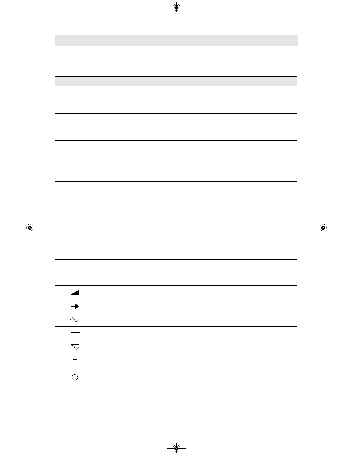
Symbols
IMPORTANT: Some of the following symbols may be used on your tool. Please study them
and learn their meaning. Proper interpretation of these symbols will allow you to operate the
tool better and safer.
Symbol Designation / Explanation
V Volts (voltage)
A Amperes (current)
Hz Hertz (frequency, cycles per second)
W Watt (power)
kg Kilograms (weight)
min Minutes (time)
s Seconds (time)
⌀
Diameter (size of drill bits, grinding wheels, etc.)
n
0
No load speed (rotational speed at no load)
n Rated speed (maximum attainable speed)
.../min
Revolutions or reciprocation per minute (revolutions, strokes, surface speed,
orbits etc. per minute)
0 Off position (zero speed, zero torque...)
1, 2, 3, ...
I, II, III,
Selector settings (speed, torque or position settings. Higher number means
greater speed)
0
Infinitely variable selector with off (speed is increasing from 0 setting)
Arrow (action in the direction of arrow)
Alternating current (type or a characteristic of current)
Direct current (type or a characteristic of current)
Alternating or direct current (type or a characteristic of current)
Class II construction (designates double insulated construction tools)
Earthing terminal (grounding terminal)
2610047991_RH328VC-36 10/4/17 8:38 AM Page 5
-6-
Symbols (continued)
IMPORTANT: Some of the following symbols may be used on your tool. Please study them
and learn their meaning. Proper interpretation of these symbols will allow you to operate the
tool better and safer.
Symbol Designation / Explanation
Designates Li-ion battery recycling program
Designates Ni-Cad battery recycling program
Alerts user to read manual
Alerts user to wear eye protection
This symbol designates that this tool is listed by Underwriters Laboratories.
This symbol designates that this component is recognized by Underwriters
Laboratories.
This symbol designates that this tool is listed by Underwriters Laboratories,
to United States and Canadian Standards.
This symbol designates that this tool is listed by the Canadian Standards
Association.
This symbol designates that this tool is listed by the Canadian Standards
Association, to United States and Canadian Standards.
This symbol designates that this tool is listed by the Intertek Testing
Services, to United States and Canadian Standards.
This symbol designates that this tool complies to NOM Mexican Standards.
2610047991_RH328VC-36 10/4/17 8:38 AM Page 6
TEMPERATURE
INDICATOR
LIGHT
Model Number RH328VC-36
Voltage rating 36 V
Shank style SDS-plus
®
Maximum Capacities:
Material
Concrete 1-1/8"
Steel 1/2"
Wood 1-1/4"
-7-
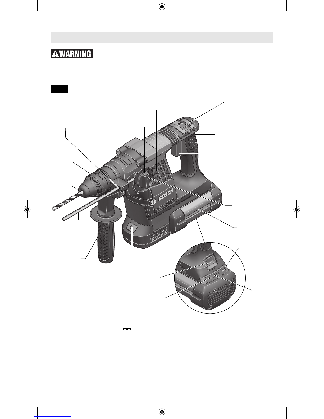
Functional Description and Specifications
Disconnect battery pack from tool or place the switch in the locked or
off position before making any assembly, adjustments or changing
accessories. Such preventive safety measures reduce the risk of starting the tool accidentally.
Cordless Hammer Drill
DUST
SHIELD
LOCKING
SLEEVE
BATTERY PACK
VARIABLE SPEED
CONTROLLED
TRIGGER
FORWARD/REVERSING
LEVER AND TRIGGER LOCK
SELECTOR DIAL
WORK LIGHT
RUBBERIZED
GRIP
VENTILATION
OPENINGS
VIBRATION
DAMPER
DEPTH GAUGE
RELEASE BUTTON
AUXILIARY
HANDLE
DEPTH
GAUGE
FIG. 1
Battery Packs/Chargers
Please refer to the Charger Manual included with your tool.
NOTE: For tool specifications refer to the nameplate on your tool.
SELECTOR DIAL
RELEASE BUTTON
BATTERY PACK
RELEASE BUTTON
BUTTON FOR
BATTERY CHARGE
CONDITION
BATTERY
CHARGE
CONDITION
LIGHT
2610047991_RH328VC-36 10/4/17 8:38 AM Page 7
Disconnect battery pack
from tool or place the
switch in the locked or off position before
making any assembly, adjustments or
changing accessories. Such preventive
safety measures reduce the risk of starting the
tool accidentally.
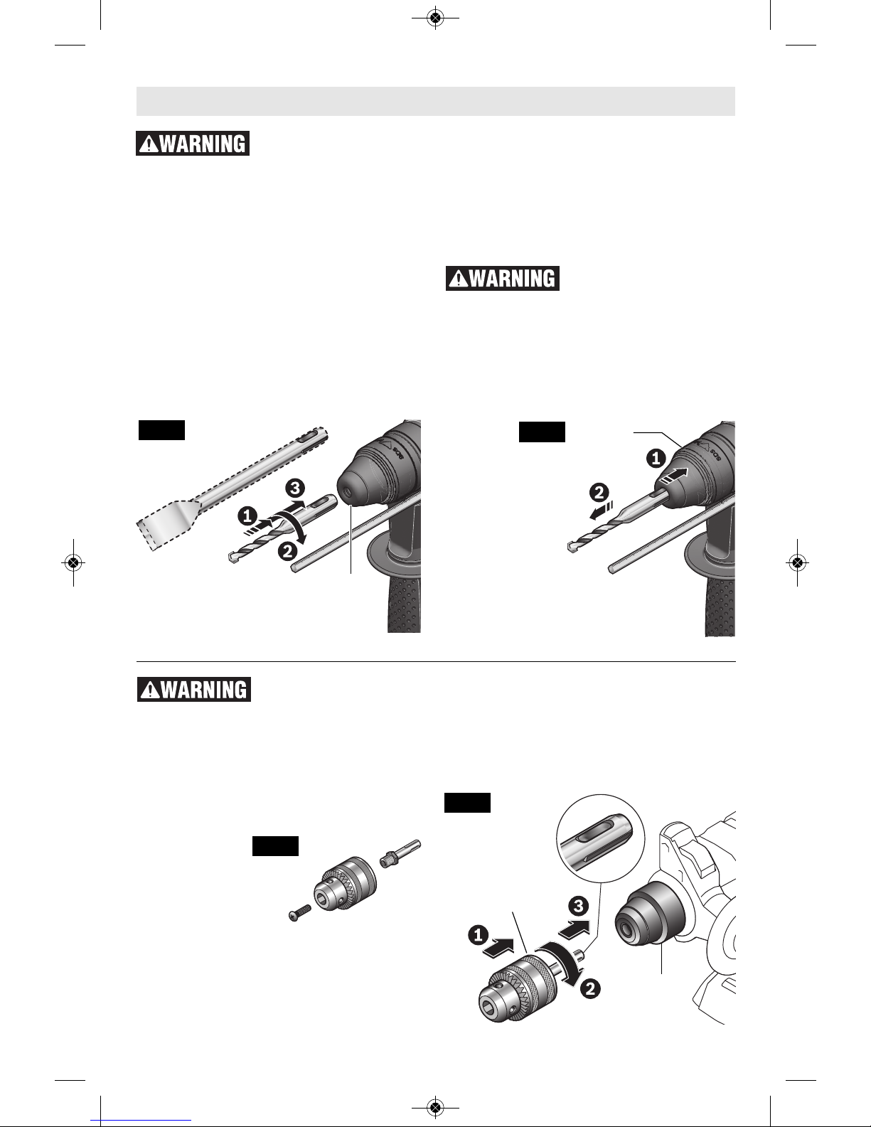
INSTALLING SDS-plus
®
ACCESSORIES
Clean the insert shank end of the accessory to
remove any debris, then lightly grease with a
light oil or lubricant.
Insert accessory into the chuck through the
dust shield, while twisting and pushing inward
until it locks automatically into place. Pull
outward on the accessory to be certain it is
locked into the chuck (Fig. 2).
NOTE: The high efficiency available from the
rotary hammers can only be obtained if sharp
and undamaged accessories are used. The
"cost" to maintain sharp and undamaged
accessories is more than offset by the "time
saved" in ope rating the too l with shar p
accessories.
REMOVING SDS-plus
®
ACCESSORIES
Accessories may be hot
after use. Avoid contact
with skin and use proper protective gloves or
cloth to remove.
To remove an accessory, pull locking sleeve
backward and pull bit forward. All accessories
should be wiped clean after removing (Fig. 3).
-8-
DUST
SHIELD
LOCKING
SLEEVE
Assembly
Disconnect battery pack
from tool or pl ace the
switch in the locked or off position before
making any assembly, adjustments or
changing accessories. Such preventive
safety measures reduce the risk of starting the
tool accidentally.
INSTALLING & REMOVING 3-JAW CHUCK
(Not included, available as accessory)
The 3 Jaw Chuck
with SDS Shank
can convert your
tool for use with
st raight shank
bits (Fig. 4).
Clean the insert shank end of the accessory to
remove any debris, then lightly grease with a
light oil or lubricant
Insert accessory into the chuck through the
dust shield, while twisting and pushing inward
until it locks automatically into place. Pull
outward on the accessory to be certain it is
locked into the chuck (Fig. 5).
To remove the chuck, pull the locking sleeve
backward (towards the rear of tool), while
pulling the chuck forward.
LOCKING
SLEEVE
3-JAW CHUCK
(Not included, available
as accessory)
FIG. 4
FIG. 5
FIG. 3
FIG. 2
2610047991_RH328VC-36 10/4/17 8:38 AM Page 8
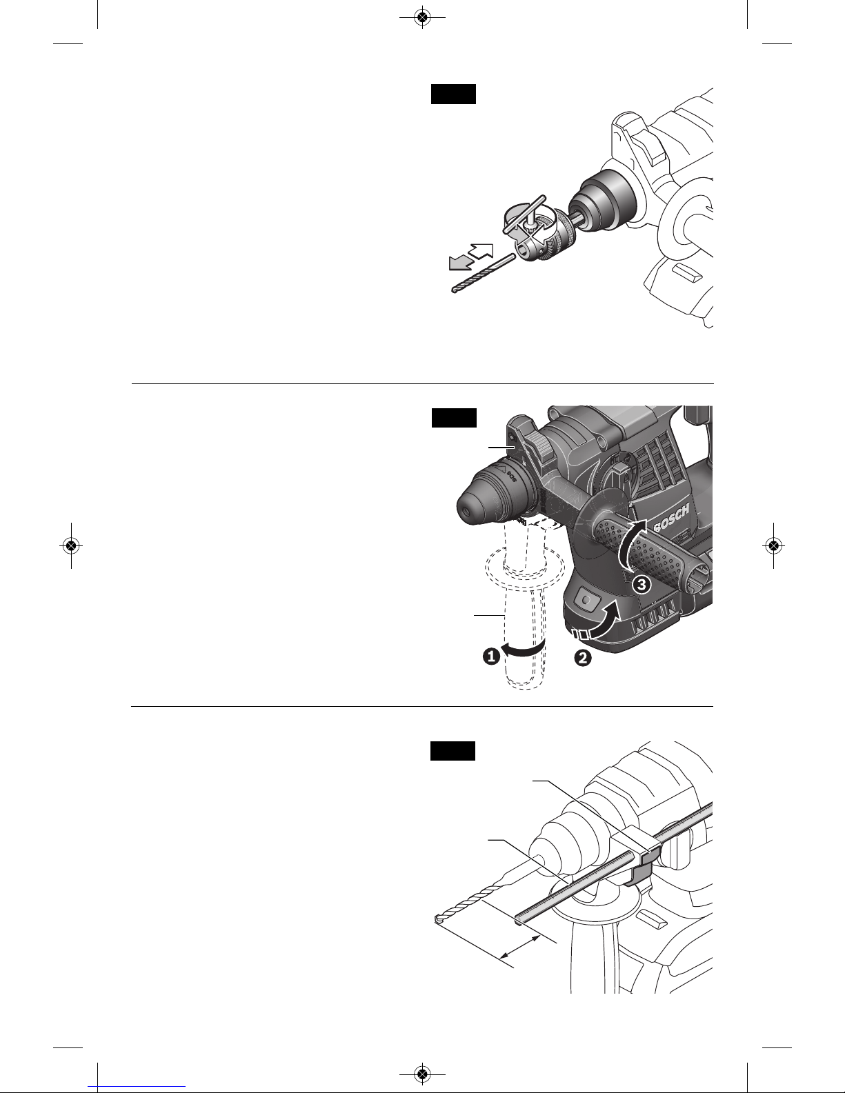
AUXILIARY HANDLE
The tool must be supported with the auxiliary
handle, which can be swiveled 360˚.
To reposit i on and / or swiv el the handle,
loosen the hand grip, move the handle to the
desired positi o n a l o n g t h e barrel and
securely retighten the hand grip (Fig. 7).
-9-
I
NSTALLING & REMOVING ACCESSORIES
3-JAW CHUCK
For small bits, open jaws enough to insert the
bit up to the flutes. For large bits, insert the bit
as far as it will go. Center the bit as you close
th e jaws by hand. This posit ions the bit
properly, giving maximum contact between the
chuck jaws and the bit shank (Fig. 6).
To tighten chuck, insert key into each of the
three key holes in succession and tighten
clockwise firmly.
The chuck can be released by using one hole only.
Note: The 3-Jaw Chuck is for use only in “Drill
only” mode. The 3-Jaw Chuck is not for use
when drilling with hammering action.
2
FIG. 6
AUXILIARY
HANDLE
DEPTH GAUGE
Your drilling depth can be pre-set and/or
repeated by using the depth gauge.
Setting depth: After the auxiliary handle is
installed, make sure the accessory has been
fully inserted into the tool holder before
setting the depth gauge (Fig. 8).
To adjust d epth, p u sh the depth g a uge
release button, slide the depth gauge to
desi r e d depth and releas e pressure on
button to lock the depth gauge in place.
X
DEPTH
GAUGE
DEPTH GAUGE
RELEASE BUTTON
FIG. 7
FIG. 8
HAND
GRIP
2610047991_RH328VC-36 10/4/17 8:38 AM Page 9
-10-
VARIABLE SPEED CONTROLLED
TRIGGER SWITCH
Your tool is equipped with a variable speed
trigger switch. The tool can be turned "ON" or
"OFF" by squeezing or releasing the trigger.
The speed can be adjusted from the minimum
to maximum nameplate RPM by the pressure
you apply to the trigger. Apply more pressure
to increase the speed and release pressure to
decrease speed Fig. 1).
To reduc e the risk of
inj ury imm ediate ly
discontinue use of the tool if the variable
spe ed co ntrol cease s to funct ion.
Subsequent loss of on/off control of the trigger
switch is likely.
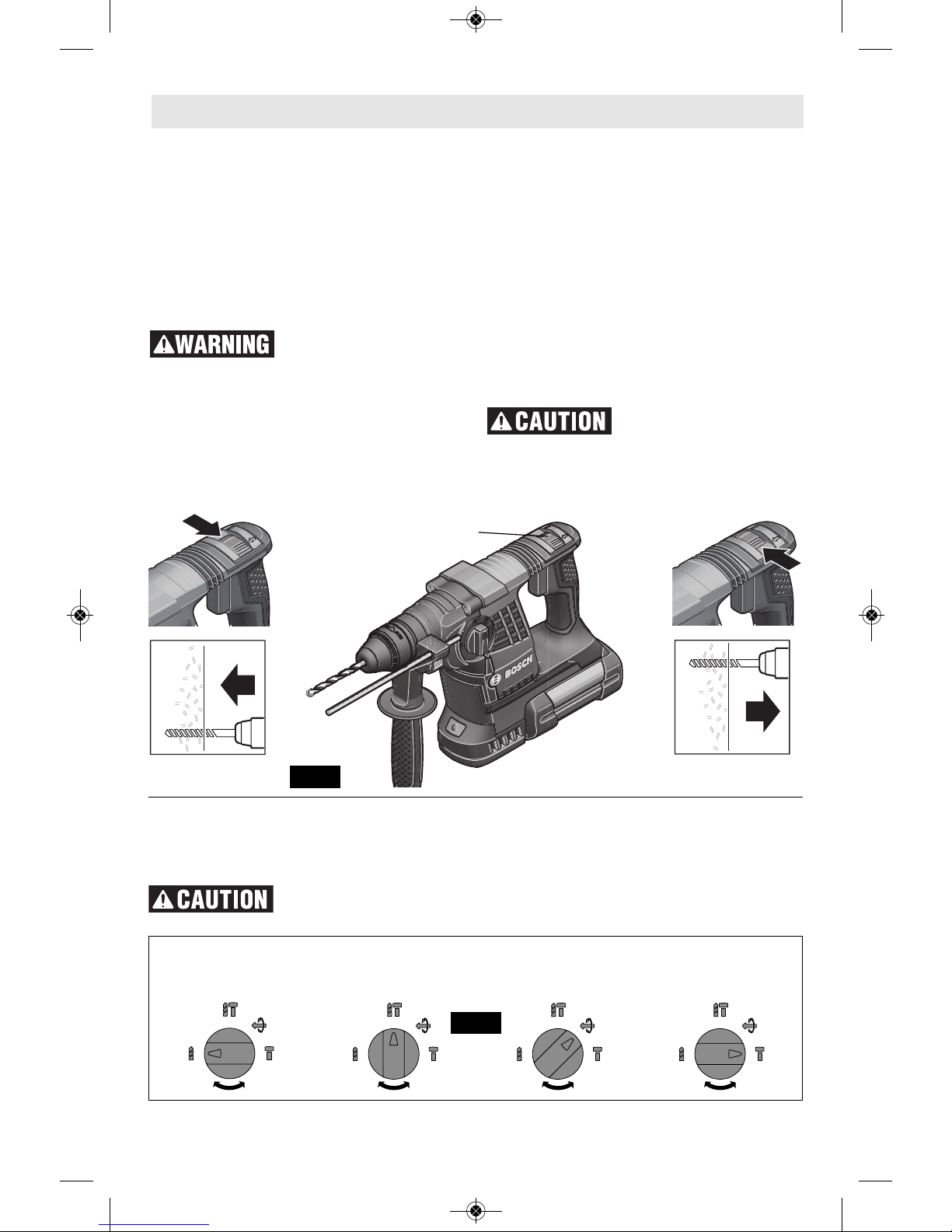
FORWARD/REVERSING LEVER &
TRIGGER LOCK
Your t ool is equipp ed w ith a f orward /
reversing lever and trigger lock located above
the trigger (Fig. 9). This lever was designed for
changing rotation of the chuck, and for locking
the trigger in an “OFF” position to help prevent
ac cidental starts and accidental batter y
discharge.
For forward rotation, (with chuck pointed away
from you) move the lever to the far left. For
reverse rotation move the lever to the far right.
To activate trigger lock move lever to the
center off position.
Do not change direction
of rotation until the tool
comes to a complete stop. Shifting during
rotation of the chuck can cause damage to the
tool.
Operating Instructions
MODE SELECTOR DIAL
The mode selector dial allows the tool to be
set for various applications as listed in the
following chart, (Fig. 10).
Do not operate the
selection dial until the
tool comes to a complete stop. Shifting during
rotation of the chuck can cause damage to the
tool.
When using demolition or chipping bits such
as bull points, chisels, spades, gouges, etc.
the “Hammer Only” mode must be selected.
Drilling only: Drilling/hammering: Vario-lock Hammering only:
used for drilling used for drilling allows for desired used for light
wood, steel, etc. concrete positions of “hammer” chipping work
FIG. 10
FIG. 9
FORWARD/REVERSING LEVER
AND TRIGGER LOCK
2610047991_RH328VC-36 10/4/17 8:38 AM Page 10

-11-
“VARIO-LOCK”
The Vario-Lock position is intended for use
with chipping bits such as bull points, spades,
gouges, etc. Choose a position which is best
suited for your operation.
Turn the mode selector dial, to the “variolock” setting. Next, rotate the locking sleeve,
along with the accessory, to the desired
position. Then turn the mode selector dial to
the “hammer only” setting and slightly turn
the locking sleeve to have it automatically
lock into a definite position (Fig. 11).
SLIP CLUTCH
The tool has a internal pre-set slip clutch. The
output spindle will stop rotating if the accessory
binds and overloads the tool.
BRAKE
When the trigger is released it activates the
electrical brake to stop the chuck quickly. This
is especially useful in the repetitive driving and
removal of screws.
ELECTRONIC PRECISION
CONTROL (EPC)
EPC assists you when working with impact in
sensitive materials by ensuring slow start-up
and reduced operating speed.
Slide the EPC switch to the desired position:
Position for ma ximum operating
speed
Position for sl ow start-up and
reduced operating speed
KICKBACK CONTROL
The rapid shut-off feature enables better
control and improves user’s comfort. The
power tool automatically shuts off in case of
sudden and unexpected rotation of the power
tool around the drilling axis (for example
jamming of the drill bit in reinforcing steel or
wedging applic ation tool) .To r estart the
machine, release the On/Off switch and then
actuate again.
Kickack Control can activate only when the
power tool is running at maximum operating
speed and can rotate freely around the drill bit
axis.
FIG. 11
FIG. 12
EPC
SWITCH
2610047991_RH328VC-36 10/4/17 8:38 AM Page 11
TOOL TIPS
Following a few simple tips will reduce wear
on the tool and the chance of injury to the
operator.
NOTE: The high efficiency available from the
rotary hammers can only be obtained if sharp
and undamaged accessories are used. The
“cost” to maintain sharp and undamaged
accessories is more than offset by the “time
sav e d” in oper a ting the tool w i th sharp
accessories.
You will extend the life of your bits and do
neater work if you always put the bit in contact
with the workpiece BEFORE pulling the trigger.
During operation, hold the drill firmly and exert
moderate, s teady pressur e. Too much
pressure at low speed will stall the hammer.
Too little pressure will keep the bit from cutting
and cause excess friction by sliding over the
surface. This can be damaging to the drill and
bit.
Shanks of all drill bits should be wiped clean
prior to using and immediately after removing.
Recall these instructions for safe operation:
1. So me materia ls requir e slow drilli ng
speeds; whereas, others require higher speed
to produce the best results.
2. All work must be supported or secured
before drilling and steady, even pressure
applied in line with the drill bit.
3. As the drill bit cuts through the opposite
side, re duce the pr essure and contin ue
running the drill as the bit is withdrawn.
Materials such as glass, porcelain, ceramics,
tiles, plastics, etc., should be drilled at low
speeds with specially designed drill bits and
lubricants.
DRILLING WOOD OR PLASTIC
If backing block is not used, ease up on the
pressure just before the bit breaks through the
wood to avoid splintering. Complete the hole
from the opposite side immediately after the
point breaks through. If bit binds, reverse the
drilling operation to help remove the bit from
the work.
DRILLING METAL
Make a center punch in the material for easier
starting. Use enough pressure to keep the bit
cutting. If the bit is allowed to merely spin in the
hole, it will become dull within a short time.
When drilling a larger hole, it is faster and
easier on your power pack to first make a
smaller hole and enlarge it to the required size.
Lubricate the tip of the bit occasionally with
CUTTING OIL for easier metal drilling. If bit
binds, reverse the drilling to help remove the
bit from the work.
DRILLING MASONRY
Use carbide-tipped masonry bit for cinder
block, mortar, common brick, soft stone and
other materials. The amount of pressure to
be used is dependent u pon the type of
material being drilled. Soft materials require
less pressure while the hard materials need
more pressure to prevent the drill bit from
spinning.
-12-
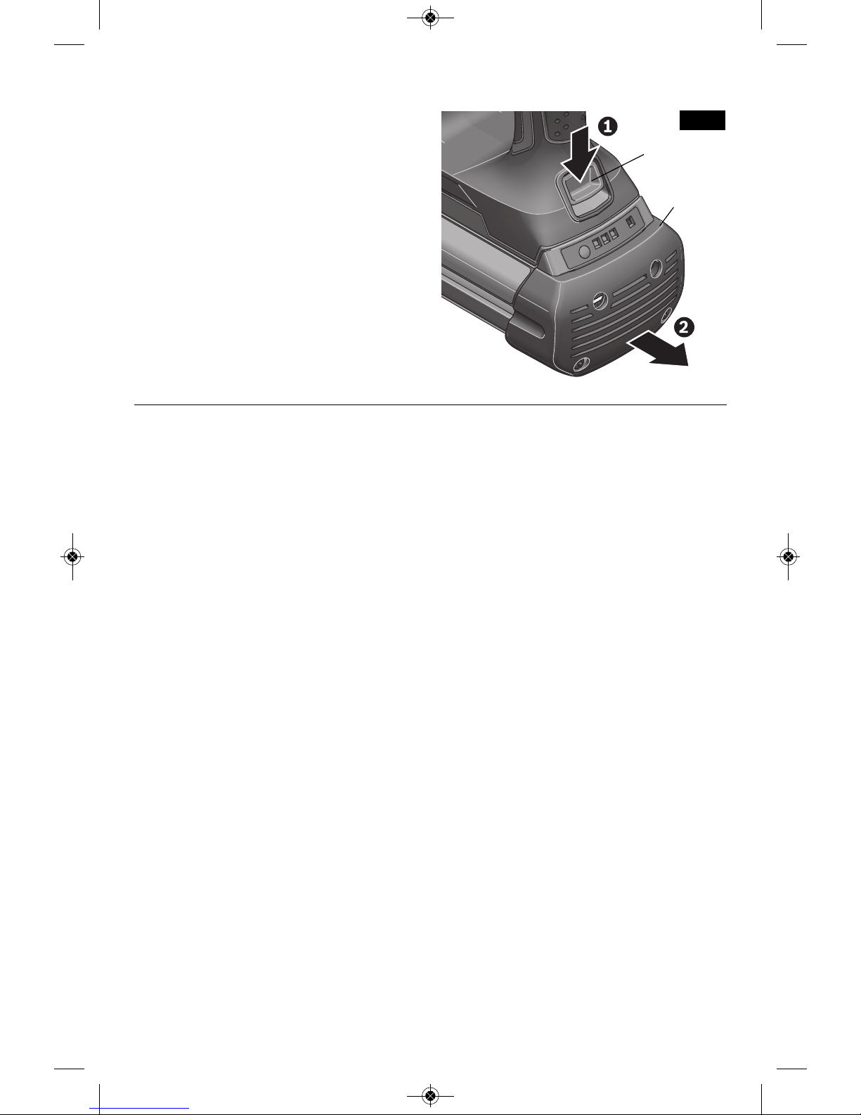
I
NSERTING AND RELEASING BATTERY PACK
Set Forward/Reversing lever to the center (off
position). Slide charged battery pack into the
housing until the battery pack locks into
p
osition.
Your tool is equipped with a secondary locking
latch to pre vent the battery pac k fro m
completely falling out of the handle, should it
become loose due to vibration.
To remove the battery pack, press the battery
pack release button and slide the battery pack
backwards.
Press the battery pack release button again
and slide the battery pack completely out of
tool housing (Fig. 13).
FIG. 13
BATTERY PACK
RELEASE
BUTTON
BATTERY
PACK
2610047991_RH328VC-36 10/4/17 8:38 AM Page 12
 Loading...