

Bosch RFRC-OPT, RADION RFRC-OPT Reference Manual
RADION receiver OP
RFRC-OPT
en Reference Guide


Table of contents
1
Introduction 5
1.1 About documentation 5
1.2 Bosch Security Systems, Inc. product manufacturing dates 5
2
General installation 7
2.1 Installation workflow 7
2.2 Unpacking information 8
2.3 Wall tamper switch installation 8
2.4 Magnet cover installation 8
2.5 Complete installation 8
2.6 Maintenance 9
3
RADION receiver OP 10
3.1 Certifications and approvals 10
3.2 RFRC-OPT Installation 11
3.2.1 RFRC-OPT configuration 11
3.2.2 Base mounting installation 12
3.2.3 Wiring considerations 12
3.2.4 Programming wireless points in the control panel 13
3.2.5 Enroll point RF ID for wireless points (Auto-learn mode) 14
3.2.6 Walk test 14
3.2.7 Complete the installation 15
3.2.8 RFRC-OPT system test 15
3.3 External LED states 15
3.4 Specifications (RFRC-OPT) 16
3.4.1 Battery requirements 17
4
RADION repeater 19
4.1 Installation considerations 19
4.2 Wiring considerations 19
4.3 Specifications 20
4.4 LEDs 20
5
RADION glassbreak 21
5.1 Installation considerations 21
5.2 Testing 22
5.2.1 Test the sensor 22
5.2.2 Hand clap test 24
5.3 Low battery 24
5.4 Wall Tamper Tab 24
5.5 Maintenance 24
6
RADION TriTech 25
6.1 Mounting height and range adjustment 25
6.2 Sensitivity settings 26
6.2.1 Standard sensitivity 26
6.2.2 Intermediate sensitivity 26
6.3 Walk testing 26
7
RADION PIR 28
7.1 Walk testing 28
8
RADION PIR C 30
8.1 Walk testing 30
RADION receiver OP Table of Contents | en 3
Bosch Security Systems, Inc Reference Guide 02.2014 | 01 | F.01U.261.835
9
RADION smoke 32
9.1 Battery replacement 33
9.2 Smoke test 33
9.3 Sensitivity test 33
9.4 Test/Silence button 34
9.5 LED 34
9.6 Clean the detector and replace the optical chamber 34
10
RADION contact SM 36
10.1 Installation considerations 36
11
RADION contact RM 38
11.1 Installation considerations 38
12
RADION specialty 40
12.1 Applications for this product 40
12.2 Installation consideration 41
13
RADION universal transmitter 42
13.1 Installation considerations 43
13.2 Reed switch settings 43
14
RADION keyfob 45
14.1 RADION keyfob FB 45
14.2 RADION keyfob TB 46
15
RADION panic 48
16
Appendices 50
4 en | Table of Contents RADION receiver OP
02.2014 | 01 | F.01U.261.835 Reference Guide Bosch Security Systems, Inc
Introduction
This document contains the basic information that a trained installer needs to install the
RADION system. It supplements the documents listed inside the packaging (graphical
installation guides).
This reference guide contains:
– A description of the general installation procedure.
– Device-specific installation procedures.
– Specification information.
How to use this document
The information contained in this document is constructed in a manner that is systematic and
sequential for the installer on a “point of need” basis. The following represents a basic outline
of that information;
– Chapter 1 (this chapter) – introductory information and how to use this document.
– Chapter 2 – basic RADION system-wide general installation information and workflow
check list.
– Chapter 3 – RADION receiver-specific installation information.
– Remaining chapters – RADION device-specific installation information.
– Appendix – description of various icons and symbols used within the RADION
documentation.
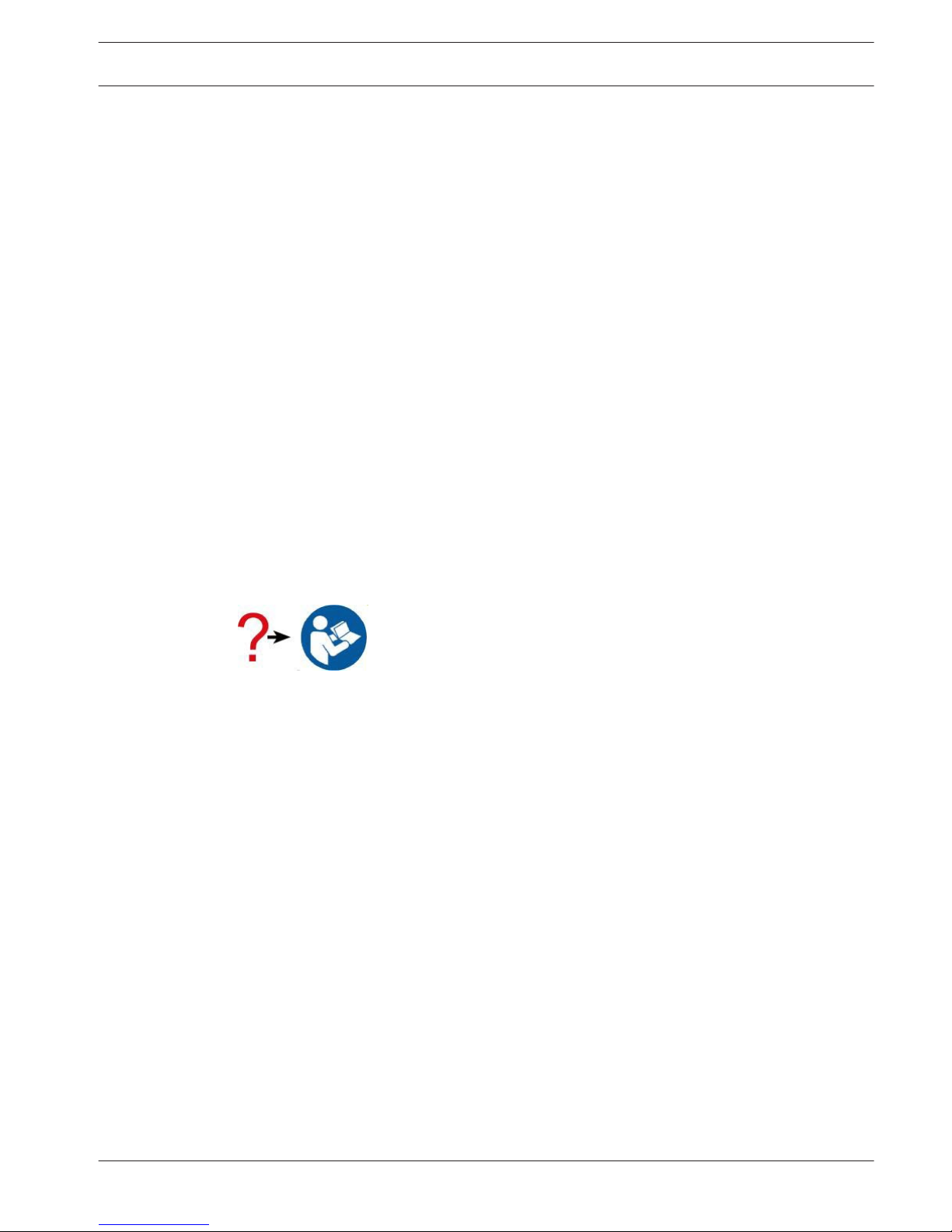
Icons and symbols
When you see the following logo in the RADION graphical installation guides listed in Table
3.1, refer to the appropriate section in this document.
Additional icons and symbols, which appear in the RADION graphical installation guides, are
explained in the appendix section of this guide. Refer to the Appendices, page 50 for more
information.
About documentation
Copyright
This document is the intellectual property of Bosch Security Systems, Inc. and is protected by
copyright. All rights reserved.
Trademarks
All hardware and software product names used in this document are likely to be registered
trademarks and must be treated accordingly.
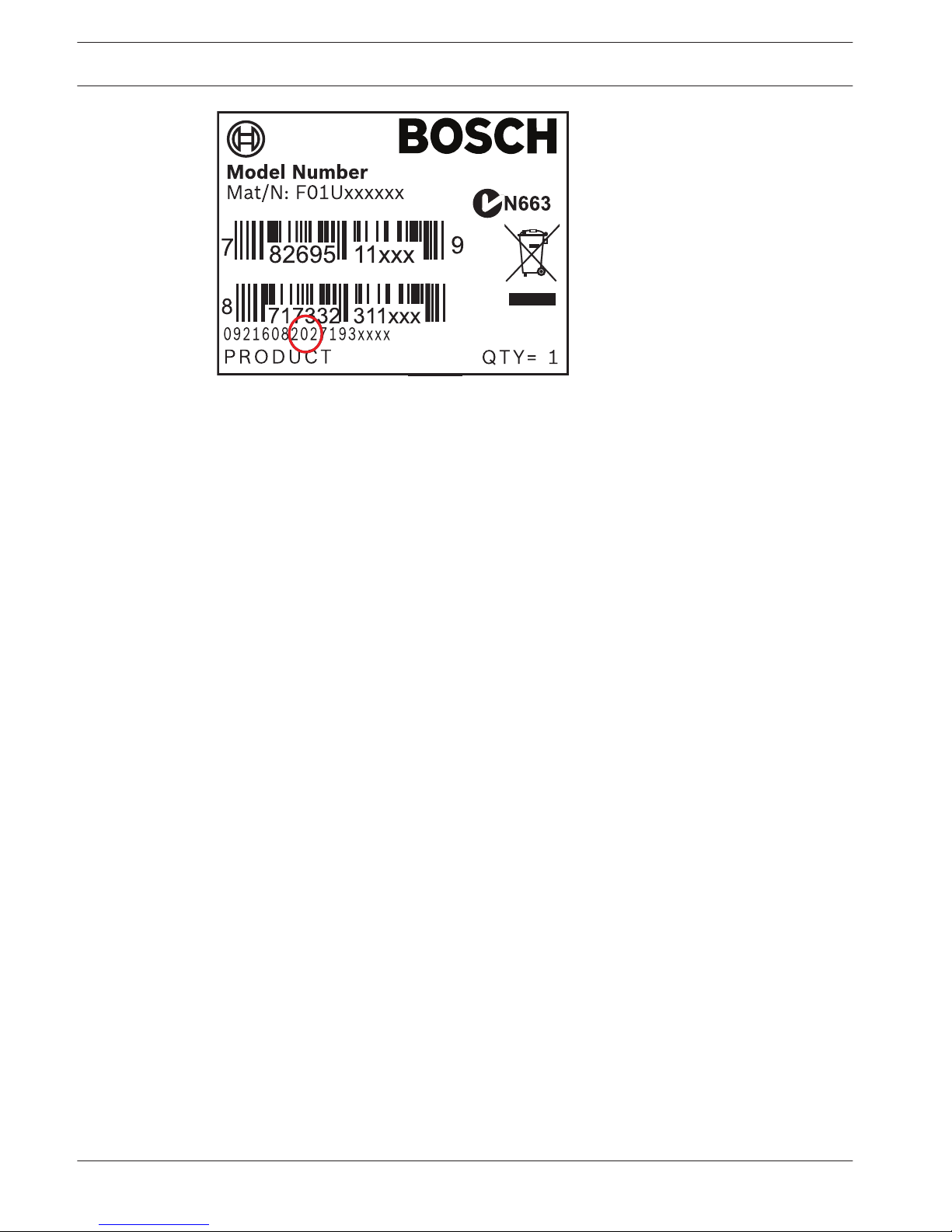
Bosch Security Systems, Inc. product manufacturing dates
Use the serial number located on the product label and refer to the Bosch Security Systems,
Inc. website at http://www.boschsecurity.com/datecodes/.
The following image shows an example of a product label and highlights where to find the
manufacturing date within the serial number.
1
1.1
1.2
RADION receiver OP Introduction | en 5
Bosch Security Systems, Inc Reference Guide 02.2014 | 01 | F.01U.261.835
6 en | Introduction RADION receiver OP
02.2014 | 01 | F.01U.261.835 Reference Guide Bosch Security Systems, Inc
General installation
Phases of installation
The installation of the RADION system is achieved by following the sequential process as
defined in this chapter. Overall, there are four main phases;
– Planning
– Physical installation of the devices
– System enrollment/configuration
– System testing (walk test, pattern test)
It is essential that these steps or phases are adhered to in the order mentioned above for
proper functionality and operation.
When installing a RADION system, you must plan your installation based on the control panel
and RADION device specifications, and the radio-frequency signal strength (RFSS) between
devices, receivers, and control panels.
Installation considerations
– RADION devices are intended only for indoor, dry applications.
– Mount RADION devices on flat, rigid surfaces. Some devices can be optionally corner
mounted as indicated in the installation instructions.
– Avoid mounting RADION devices in areas with large, metallic objects, electrical panels, or
electric motors. They might reduce the radio-frequency (RF) range of a RADION device.
– Avoid installing the devices where excessive humidity, moisture, or temperatures outside
of the acceptable operating range exist.
– Wire all objects according to their specifications.
– RADION devices use batteries of varying types. When installing batteries, observe safety
and polarity recommendations as indicated in the documentation for those products.
Installation workflow
To install, configure, and test the system, use the workflow below and follow in sequential
order, from top to bottom, checking each box as you complete a step.
Notice!
Always power down the control panel when connecting modules, or other wiring. Power
down the control panel by unplugging the transformer and disconnecting the battery
Plan the installation of the RADION system
Install the RADION components (refer to the graphical installation guides and this system
reference guide for details)
Program wireless points in the control panel
Enroll point RF ID for wireless points
Verify LED responses on devices
Perform a local walk test for installed detectors
Review signal strength and margin of each point
Complete the installation
2
2.1
RADION receiver OP General installation | en 7
Bosch Security Systems, Inc Reference Guide 02.2014 | 01 | F.01U.261.835
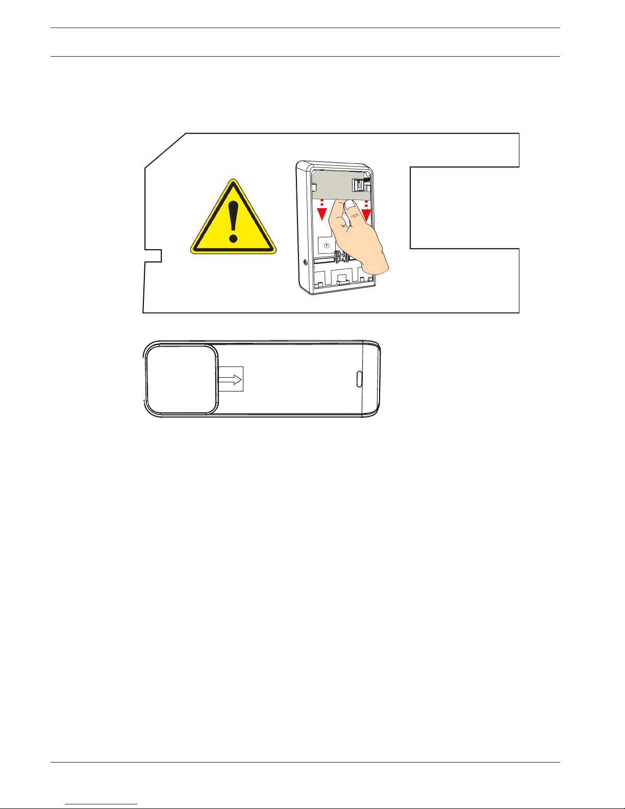
Unpacking information
When unpacking the receiver, repeater, or bill trap device, it is important to remove the
cardboard insert as illustrated below;
Figure 2.1: Insert for the receiver and repeater
Figure 2.2: Insert for the bill trap
Wall tamper switch installation
RADION transmitter devices contain a feature that activates the wall tamper switch located on
the base of the device. In order to properly install the device, you must consider the following:
– To properly install a device with active wall tamper functionality, insert a screw in the
designated screw slot location.
– Failure to insert a screw into the wall tamper slot prevents the wall tamper feature from
generating a tamper signal when the transmitter is pulled away from a wall.
Magnet cover installation
During the installation of the plastic magnet cover, the cover is not designed to be separated
from the base after the base and cover are snapped together. Damage to the plastics may
occur if separated.
Complete installation
Testing the entire RADION system can only be achieved by performing an area wide test
through the control panel and corresponding keypad(s). This is achieved by performing an
overall service walk test. Refer to your control panel documentation for system-walk, or other
system-wide testing procedures.
2.2
2.3
2.4
2.5
8 en | General installation RADION receiver OP
02.2014 | 01 | F.01U.261.835 Reference Guide Bosch Security Systems, Inc
To ensure proper operation of the RADION devices, test the basic functionality of the device
locally. Depending on the RADION device to be tested, perform the following procedures for
functionality:
– When testing the receiver, power up the compatible control panel in which the receiver is
connected to and observe the LED behavior on the receiver.
– Local walk testing can be performed on the motion detectors as defined in the tritech
and PIR chapters of this guide.
– Magnet testing can be performed by opening or closing the door/window in which the
magnet is installed on.
Maintenance
It is recommended to check the battery of each device annually. This will ensure proper
operation and functionality of the devices.
Battery Life Extension feature (PIR and TriTech)
In the normal operating mode, an alarm can be transmitted only after three (3) minutes have
passed since the previous alarm restoral. This 3 minute lockout time reduces unnecessary RF
transmissions in high traffic areas, thereby extending battery life.
2.6
RADION receiver OP General installation | en 9
Bosch Security Systems, Inc Reference Guide 02.2014 | 01 | F.01U.261.835
RADION receiver OP
RADION receiver OP is a wireless receiver that connects RADION wireless peripherals to
supported Bosch option bus control panels via the terminal block connection. A compatible
control panel powers the receiver through the wiring connection. Features include:
– Easy addressing via a rotary switch
– Cover and wall tamper protection
– RFID and configuration data are contained in persistent memory
– External LEDs
– Detection and reporting of radio frequency interference
Notice!
The Option Bus receiver does not support key fob supervision
Use this reference guide along with the control panel’s documentation and each device’s
installation instructions to complete the installation process.
Product Description Document
RFRC-OPT RADION receiver OP Graphical installation guide (P/N: F01U261830)
RFBT RADION specialty Graphical installation guide (P/N: F01U261814)
RFDL-11 RADION TriTech Graphical installation guide (P/N: F01U261815)
RFDW-RM RADION contact RM Graphical installation guide (P/N: F01U291208)
RFDW-SM RADION contact SM Graphical installation guide (P/N: F01U261817)
RFKF-TB/RFKF-FB RADION keyfob Graphical installation guide (P/N: F01U261820)
RFPB-SB/RFPB-TB RADION panic TB Graphical installation guide (P/N: F01U261821)
RFPR-12 RADION PIR Graphical installation guide (P/N: F01U261822)
RFPR-C12 RADION PIR C Graphical installation guide (P/N: F01U261823)
RFRP RADION repeater Graphical installation guide (P/N: F01U261824)
RFSM RADION smoke Graphical installation guide (P/N: F01U261825)
RFGB RADION glassbreak Graphical installation guide (P/N: F01U261818)
RFUN RADION universal Graphical installation guide (P/N: F01U261826)
Table 3.1: RADION Wireless products
Certifications and approvals
Listings and approvals
Europe
The RFRC-OPT is EN listed for EN50131-3: 2009, EN50131-5-3: 2005 + A1: 2008, and
EN50130-5 Environmental Class II.
As a manufacturer of batteries or devices containing batteries, we are obliged to inform you of
the following in accordance with the Battery Ordinance:
– Batteries must not be disposed of in household waste.
3
3.1
10 en | RADION receiver OP RADION receiver OP
02.2014 | 01 | F.01U.261.835 Reference Guide Bosch Security Systems, Inc
– As a consumer, you are legally obliged to take batteries to a suitable collection point.
– You can return used batteries free of charge to the point of sales or to a communal
collection point.
– Batteries can contain substances that are hazardous to the environment or health.
– Only dispose of discharged batteries in the container provided and, in the case of lithium
batteries, mask the poles.
Batteries are identified with a crossed out trash can symbol.
If the batteries contain specific harmful substances, the chemical symbols are also indicated:
– Cd - Cadmium
– Pb - Lead
– Hg - Mercury
RFRC-OPT Installation
Use the provided anchors and screws to mount the receiver in locations accessible for future
maintenance. Mount the receiver onto a wall.
For best receiver reception results, place the receiver in a central location among the
transmitters. For optimal communication results in situations where there is a long distance
between the transmitting device and the system receiver, it might be necessary to install
repeaters.
Notice!
Mount the receiver in a location away from metal objects. Metal objects (duct work, wire
mesh screens, boxes) reduce RF range.
RFRC-OPT configuration
RADION Wireless System operates on a radio frequency of 433.42 MHz.
Configuring the address switch
The address switch determines the receiver’s numeric address value which the receiver will
use to report receiver status information to the control panel. Set the address to the receiver
prior to installation. Address 1 through 8 are valid address settings for the receiver. Use a
slotted screwdriver to set the address switch.
Address settings
The receiver address switches provide a single-digit setting for the receiver’s address. The
receiver uses addresses 1 through 8. Addresses 0 and 9 are invalid and will cause the receiver
to enter into an Option bus communication error state. This will cause the receiver to be
unrecognized by the control panel. Refer to your control panel documentation for information
on the valid addresses for that control panel. The figure below shows the address switch
setting for address 1.
3.2
3.2.1
RADION receiver OP RADION receiver OP | en 11
Bosch Security Systems, Inc Reference Guide 02.2014 | 01 | F.01U.261.835
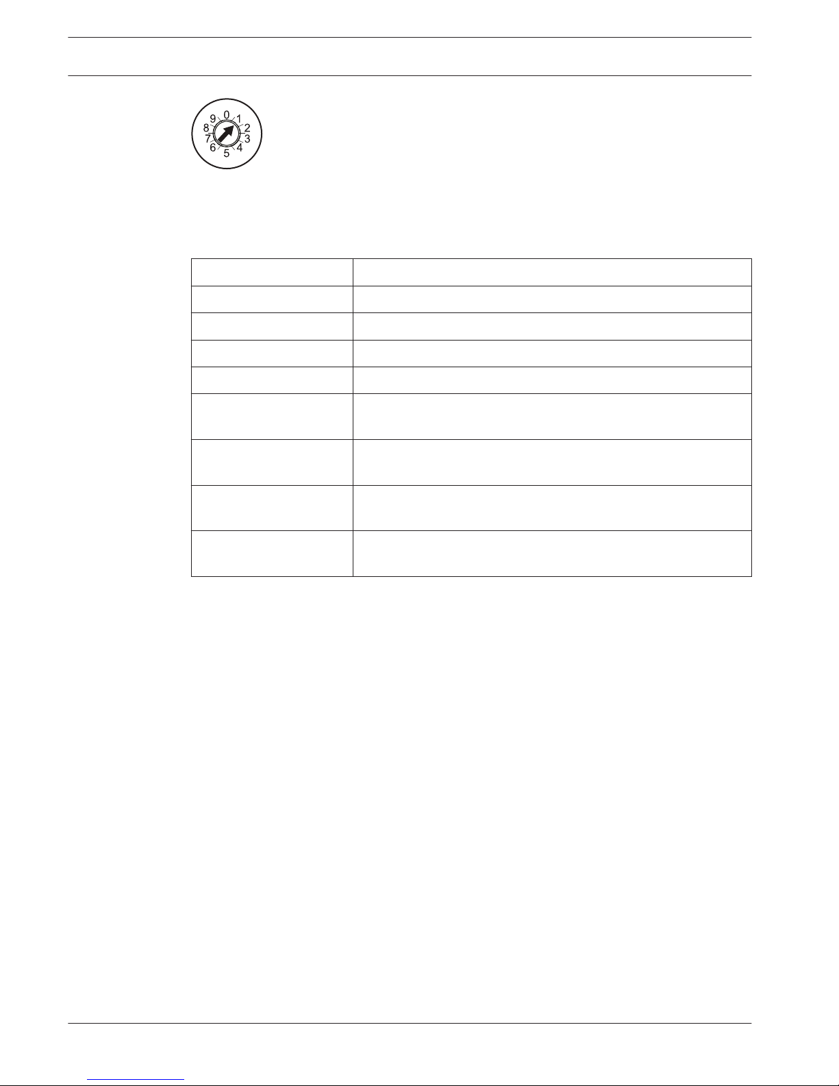
Figure 3.1: Address switch set to 1
Option Bus address settings
Depending on the supporting control panel, use the following table as a reference when
selecting the address setting switch for the compatible control panel.
Address switch setting Function
1 RADION receiver 1
2 RADION receiver 2
3 Legacy Mode receiver 1
4 Legacy Mode receiver 2
5 Maintenance Mode, EN50131 Grade 2 (6dB attenuation), for
RADION receiver 1
6 Maintenance Mode, EN50131 Grade 2 (6dB attenuation), for
RADION receiver 2
7 Maintenance Mode, EN50131 Grade 2 (6dB attenuation), for
legacy receiver 1
8 Maintenance Mode, EN50131 Grade 2 (6dB attenuation), for
legacy receiver 2
Table 3.2: Option Bus address settings
The receiver and control panel establish communication between each other when the
appropriate address switch is selected.
Base mounting installation
Some consideration and planning are required when locating a position to mount the base of
the receiver onto the desired surface. The base must be mounted in such a way that provides
plenty of accessible space to insert a flat-headed screwdriver, and remove the receiver cover
when maintenance and troubleshooting scenarios occur.
Because of the location of the opening mechanism on the side of the device, you will need
approximately 254 mm (10 in) of clearance on one side of the base to provide easy access to
the opening mechanism, and approximately 15 mm (0.6 in) of clearance on the opposite side
to compensate for the physical dimensions of the device cover. This should allow for adequate
space in which the device cover can be opened, and the cover removed, should the need
arise.
Other mounting considerations include;
– Minimum clearance above the location to compensate for the vertical sliding movement
to attach or remove the device from the base is: >30 mm (1.2 in).
– Minimum clearance below the location where the base is mounted: >23 mm (0.9 in).
Wiring considerations
3.2.2
3.2.3
12 en | RADION receiver OP RADION receiver OP
02.2014 | 01 | F.01U.261.835 Reference Guide Bosch Security Systems, Inc
Notice!
Do not install long cable runs next to high-current power feeds. Keep cable lengths as short
as possible to minimize noise pickup.
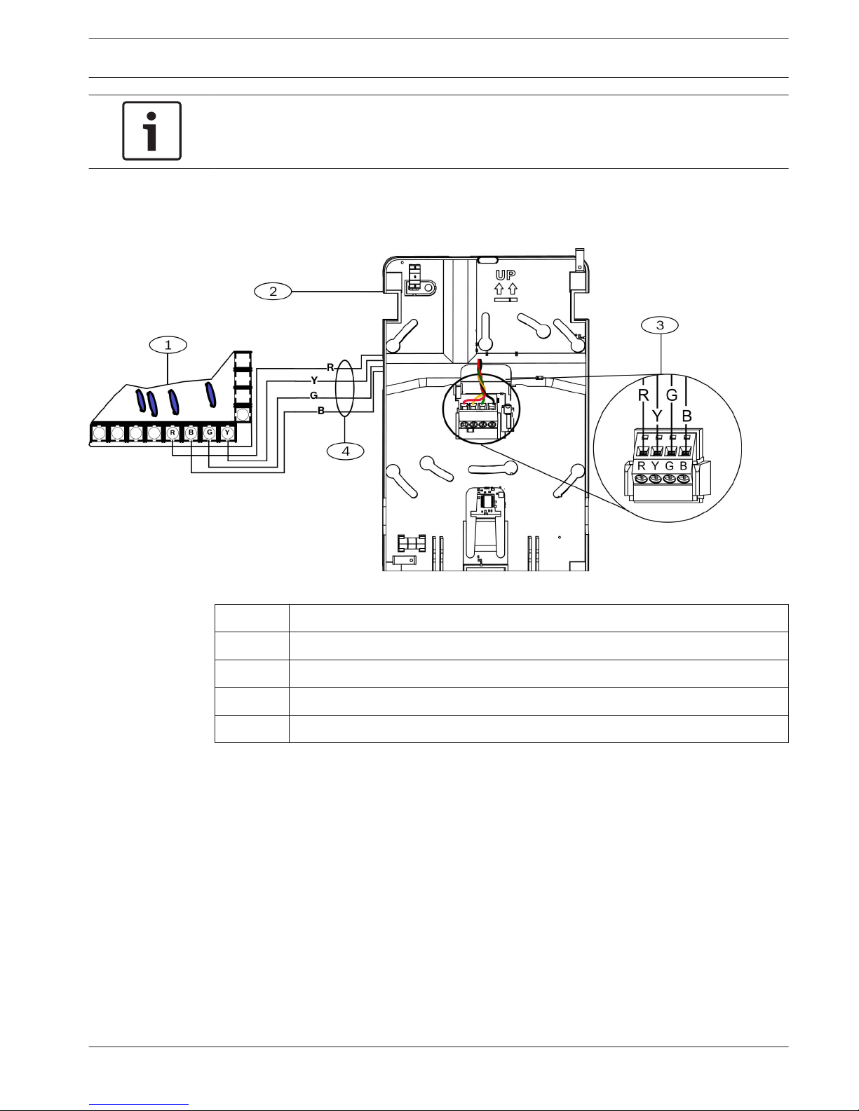
Ensure that the wiring used meets the following specifications:
– Four-conductor unshielded 0.65 mm (22 AWG) to 2.0 mm (18 AWG) maximum.
– Wire length must not exceed 300 m (1000 ft) from the control panel
Figure 3.2: Wiring to an Option Bus Terminal Strip
Callout Description
1 Control Panel
2 RADION receiver OP
3 Terminal Block
4 Terminal Wiring
Programming wireless points in the control panel
After completing the physical installation of the RADION system, you must configure the
RADION points in order to establish communication between the RADION system and the
supported Option bus control panel. This can be accomplished by using one of two methods:
– Using remote programming software on a supported laptop computer, or
– Compatible keypad devices to enable your points
A “point” can be a detection device, or a group of devices connected to your security system.
The first step to enable communication is to verify that the RADION transmitter is
programmed into the supporting control panel. This is achieved by configuring a point source
index as wireless, and then associating a transmitter’s RFID with that point source index
RFID programming from a supported keypad is achieved by two methods;
– Through the point source/RFID menu options, or
– Enroll point RFID for wireless points – which uses the “Auto-Learn” methodology
3.2.4
RADION receiver OP RADION receiver OP | en 13
Bosch Security Systems, Inc Reference Guide 02.2014 | 01 | F.01U.261.835
The preferred method of entering in the RFID number would be to enter it in manually via the
keypad – point source/RFID, or remote programming software. Doing so gives you greater
control and security, while reducing the risk of incomplete RFID programming.
For more information on programming wireless points in the control panel, refer to the
Installation and Operation manual of the compatible control panel on registering the receiver.
Enroll point RF ID for wireless points (Auto-learn mode)
A second RFID Programming option exists whereby new devices are “Auto Learned” on the
system. Auto Learn Mode is the process through which the control panel identifies and enrolls
new device RF ID’s that appear within the system. This is achieved by the following:
– Keyfobs – when the keyfob buttons are pressed, then released.
– Detectors – when the battery is inserted, or if the detector is faulted.
Notice!
The Auto Learn mode option is not recommended as the preferred method of entering in the
RF ID’s due to the potential of the RADION system picking up the first available RF ID it
detects. For optimal results, manually enter in the RF ID’s through the supported keypad, or
via RPS.
For more information on enrolling RF ID’s in the control panel, refer to the Installation and
Operation manual of the compatible control panel on enrolling RF ID‘s.
Walk test
Use the following pattern testing procedure to test the detector range and functionality.
Motion walk test
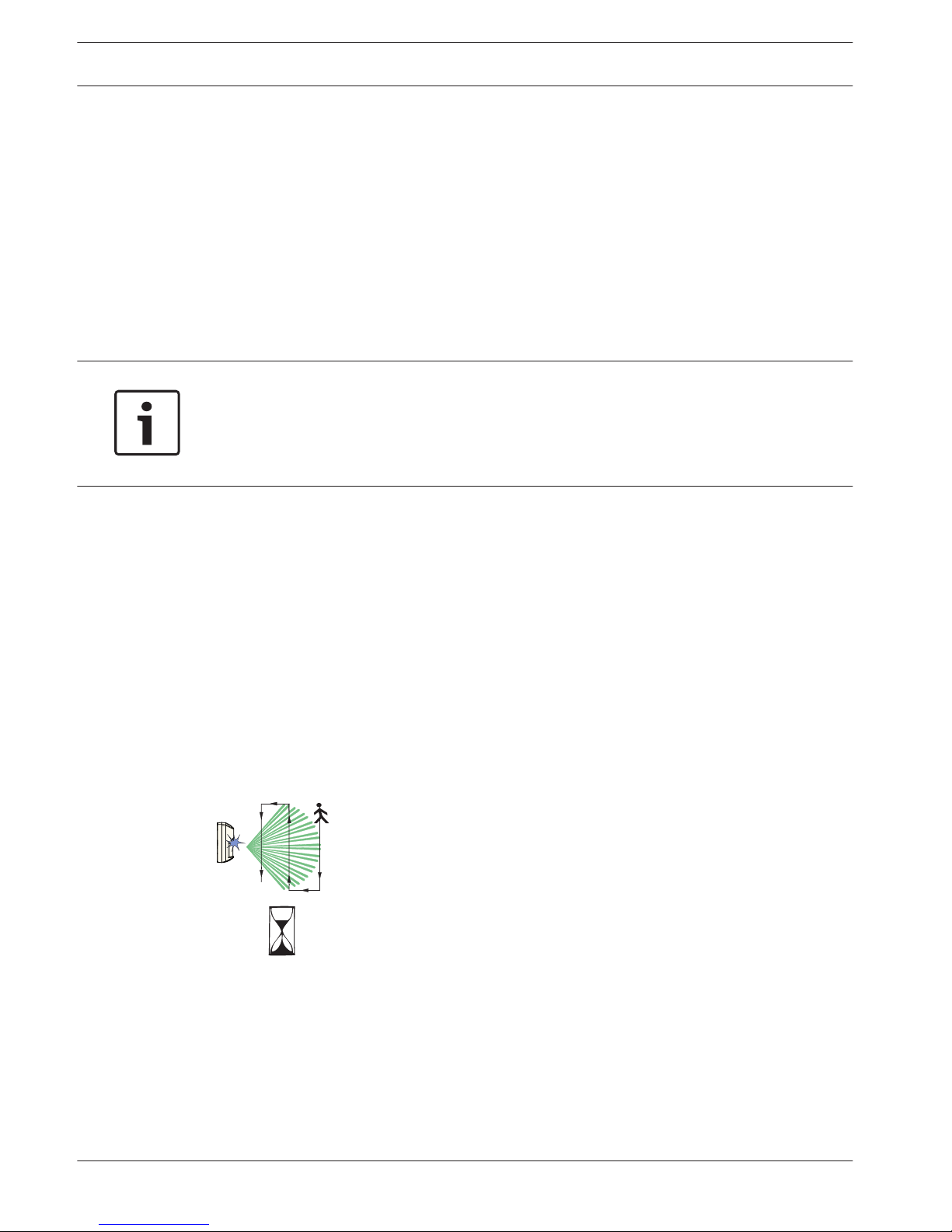
Remove and replace cover to activate a 90-sec Walk Test Mode. During this Test Mode, any
activity in the sensor’s coverage pattern will cause a transmitted alarm and LED activation.
Each alarm will also extend the Test Mode for an additional 90-sec. Walk Testing should be
done across the coverage pattern. The edge of the coverage pattern is determined by the first
flash of the LED. This may change slightly depending upon the sensitivity setting. Walk Test
the unit from both directions to determine the pattern boundaries. Although generally not
required, if masking is desired, the lens diagram shows the appropriate areas to be masked.
Use an opaque material (such as, electrical tape) to mask the desired areas.
90 sec
Figure 3.3: 90 sec walk test
Final test
While the detector is in the Walk Test Mode, turn on all heating and air conditioning sources
which would normally be active during the protection period. Stand away from the sensor and
outside the coverage pattern and watch for alarms. After setup and tests are completed, and
there has been no activity in the sensor’s coverage pattern for approximately 90-sec, the LED
will flash to indicate that the Walk Test mode is ending.
3.2.5
3.2.6
14 en | RADION receiver OP RADION receiver OP
02.2014 | 01 | F.01U.261.835 Reference Guide Bosch Security Systems, Inc
Maintenance
At least once a year, a walk test should be performed to verify the range and coverage for
proper operation.
Magnet walk test
Perform a magnet test to ensure proper functionality of the door and window contacts.
Magnet testing can be performed by opening or closing the door/window in which the magnet
is installed. In this test, you are verifying the distances of which the magnet engages and
disengages the transmitter.
Complete the installation
Depending on the results of testing the RADION system from a system-wide approach (walk
test, signal strength and margin tests), make the appropriate modifications/adjustments to
complete the install process.
RFRC-OPT system test
Overall system test
It is recommended by to test the entire system at least once every year, including the RFRCOPT receiver by an installer to ensure proper functionality of the RADION system.
External LED states
The receiver utilizes the External LED to show various states of the receiver. These states fall
into the following three categories:
– Normal state
– Communication error state
– Trouble state
– Maintenance state
– Off state
Normal state:
The receiver enters a normal state when it has passed all power self-tests and has established
a communication link with the control panel . The receiver remains in this state as long as the
communication link is present, and no other issues are present that would prevent the
receiver from operating in a normal condition.
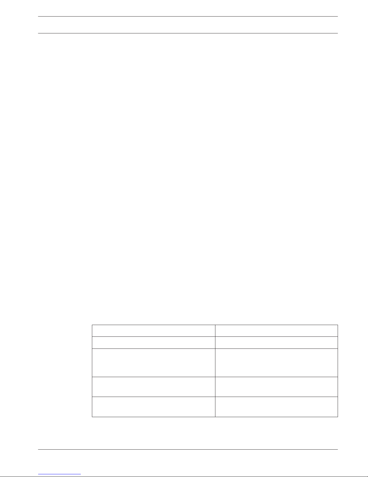
LED condition
State description
On (Normal) Indicates the receiver is functioning normally.
Continuous slow flash: 1 sec On, 1 sec Off Indicates the receiver is being programmed
with the zone and transmitter ID’s from the
compatible control panel.
Turns Off momentarily Indicates the receiver obtained a valid
transmission from a RADION transmitter.
Flash 3 times Indicates the receiver has obtained a new
device ID while in “Learn Mode.”
3.2.7
3.2.8
3.3
RADION receiver OP RADION receiver OP | en 15
Bosch Security Systems, Inc Reference Guide 02.2014 | 01 | F.01U.261.835
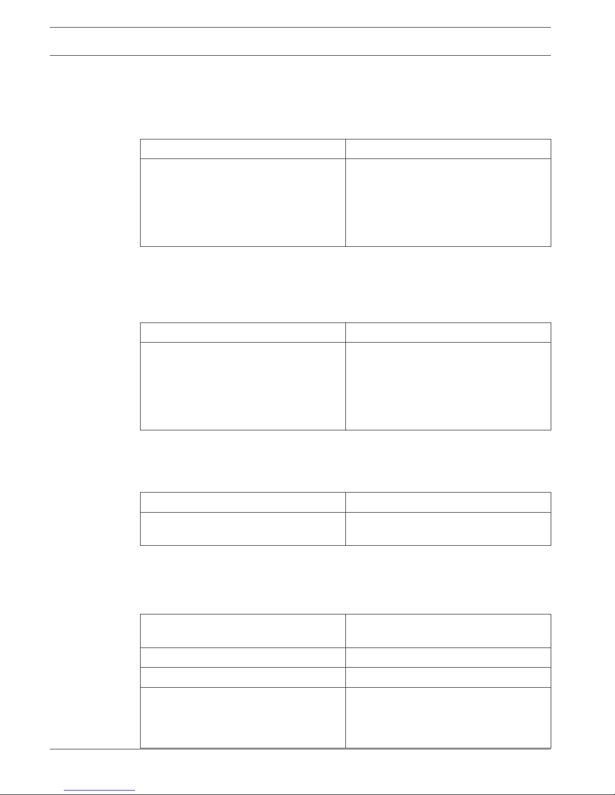
Communication error state:
The receiver enters a communication error state when, during power up, it does not establish
a link with the control panel, or has been in an idle state for more than 30 sec without
communication. Another cause for a communication error state is an invalid address switch
setting (0, or 9).
LED condition State description
3-pulse flash: A 3-pulse signal, followed by a
short delay at the end of the 3rd pulse
(Communication error)
Indicates the receiver has experienced a
communication failure. This error could be a
result of either:
– A communication failure between the
control panel and receiver, or
– An invalid address switch setting
Trouble state:
The receiver enters a trouble state when an internal self-test detects a failure. Another cause
for the receiver entering into a trouble state would be if the receiver detects radio frequency
interference failure.
LED condition
State description
Continuous fast flash: A continuous pulse
between On and Off states (Trouble state)
– Indicates the receiver is in a trouble
state, experiencing a radio frequency
interference failure
– A communication failure with internal
hardware components within the
receiver
Maintenance state
The receiver enters a maintenance state when the address switch settings are set between
switch 5 – switch 8.
LED condition
State description
Continuous Flash: A continuous pattern of
short off time, followed by long on time.
Indicates the receiver is in Maintenance
Mode.
Off state
Indicates there is a power failure to the receiver. Check the wire connections for proper
wiring.
Specifications (RFRC-OPT)
Housing Dimensions (H x W x D) 139.7 mm x 209.6 mm x 31.8 mm (5.5 in x
8.25 in x 1.25 in)
Power/Voltage 12 VDC nominal
Maximum Current Draw 100 mA
Operating Environment Functional range: -10°C to +49°C (+14°F to
+120°F)
EN 50130-5 Class II only: -10゚C to 40゚C (+14゚
F to +104゚F
3.4
16 en | RADION receiver OP RADION receiver OP
02.2014 | 01 | F.01U.261.835 Reference Guide Bosch Security Systems, Inc
Relative Humidity Up to 93% non-condensing
Frequency 433.42 MHz
Wiring Distance Maximum distance of 300 m (1000 ft) from
the control panel
Wiring Gauge 0.65 mm (22 AWG) to 2.0 mm (18 AWG)
maximum
Wall and Cover Tamper Switch – Transmits a tamper signal when the
device is removed from its base or
pulled away from the wall
Table 3.3: RFRC-OPT Specifications
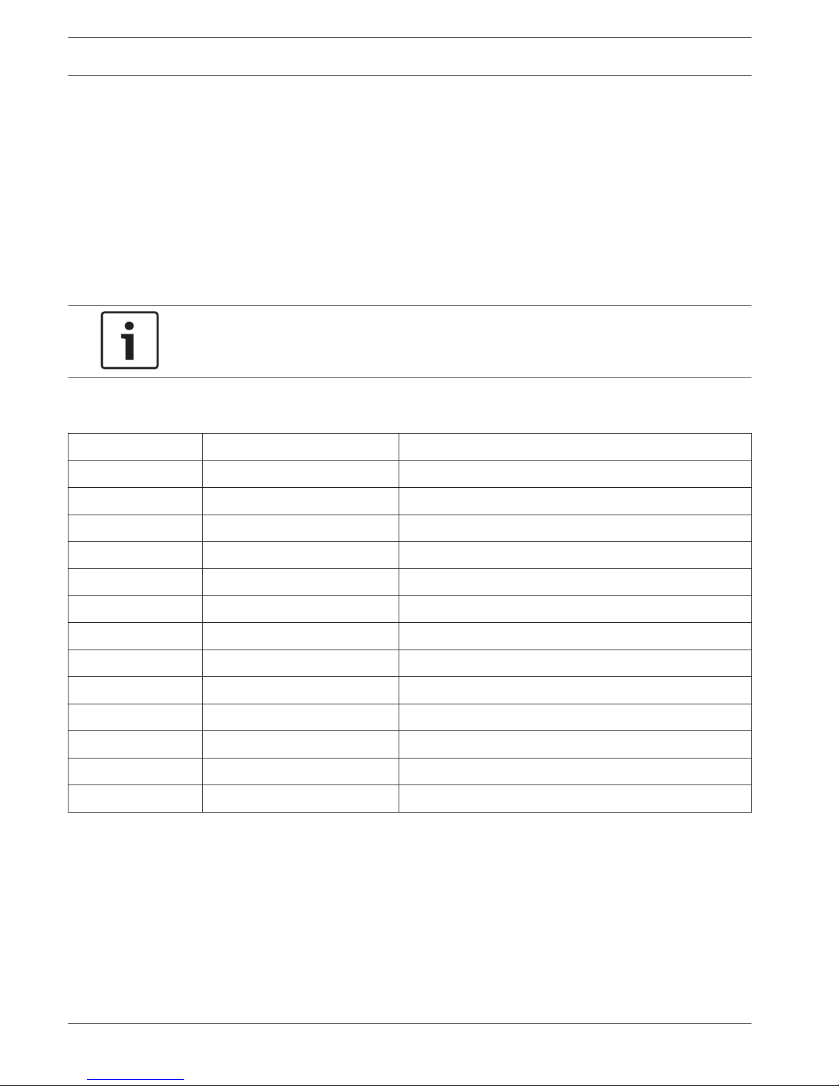
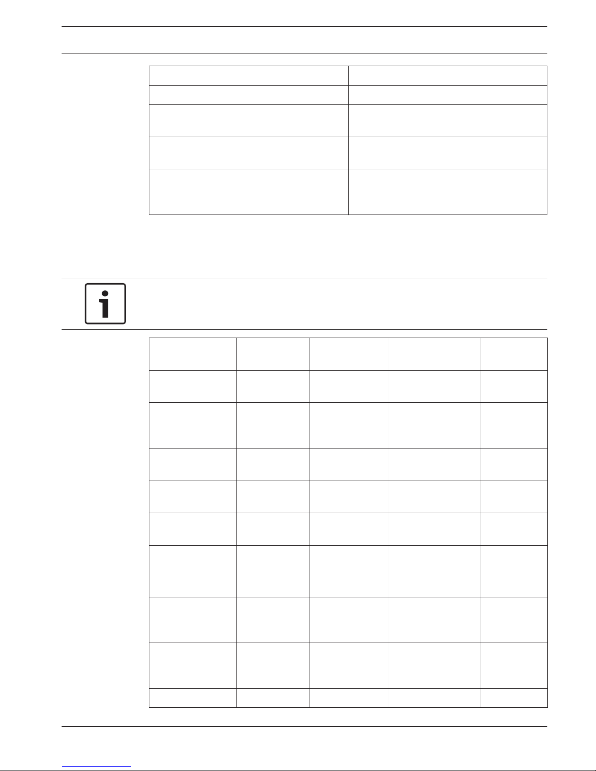
Battery requirements
Notice!
Dispose of used batteries according to manufacturer’s instructions.
RADION Device Battery Size Battery Type Cell Voltage Quantity
(Cells)
RFPR-12 PIR
motion detector
CR123A Lithium 3 VDC 1
RFPR-C12 PIR
motion detector
(curtain)
CR123A Lithium 3 VDC 1
RFRP repeater Non-
replaceable
Lithium polymer 3.7 VDC nominal 1
RFSM smoke
detector
CR123A Lithium 3 VDC 2
RFUN universal
transmitter
CR123A Lithium 3 VDC 1
RFBT bill trap AAA Lithium 1.5 VDC 1
RFDL-11 TriTech
detector
AA Alkaline 1.5 VDC 4
RFDW-SM standard
door/window
contact
AAA Lithium 1.5 VDC 1
RFDW-RM
recessed door/
window contact
AAA Lithium 1.5 VDC 1
RFGB glassbreak CR123A Lithium 3 VDC 1
3.4.1
RADION receiver OP RADION receiver OP | en 17
Bosch Security Systems, Inc Reference Guide 02.2014 | 01 | F.01U.261.835
 Loading...