


Bosch PR10E, PR20E Manual
IMPORTANT: IMPORTANT : IMPORTANTE:
Read Before Using Lire avant usage Leer antes de usar
Operating/Safety Instructions
Consignes de fonctionnement/sécurité
Instrucciones de funcionamiento y seguridad
PR10E
PR20E
For English Version Version française Versión en español
See page 2 Voir page 29 Ver la página 56
1-877-BOSCH99 (1-877-267-2499) www.boschtools.com
Call Toll Free for
Consumer Information
& Service Locations
Pour obtenir des informations
et les adresses de nos centres
de service après-vente,
appelez ce numéro gratuit
Llame gratis para
obtener información
para el consumidor y
ubicaciones de servicio
BM 2610021461 06-12_BM 2610021461 06-12.qxp 6/26/12 1:38 PM Page 1

-2-
Work area safety
Keep work area clean and well lit. Cluttered
or dark areas invite accidents.
Do not operate power tools in explosive
atmospheres, such as in the presence of
flammable liquids, gases or dust. Power
tools create sparks which may ignite the dust
or fumes.
Keep children and bystanders away while
operating a power tool. Distractions can
cause you to lose control.
Electrical safety
Power tool plugs must match the outlet.
Never modify the plug in any way. Do not
use an y adapter plugs with earthed
(grounded) power tools. Unmodified plugs
and matching outlets will reduce risk of electric
shock.
Avoid body contact with earthed or grounded
surfaces such as pipes, radiators, ranges
and refrigerators. There is an increased risk
of electric shock if your body is earthed or
grounded.
Do not expose power tools to rain or wet
conditions. Water entering a power tool will
increase the risk of electric shock.
Do not abuse the cord. Never use the cord
for carrying, pulling or unplugging the power
tool. Keep cord away from heat, oil, sharp
edges or moving parts. Damaged or entangled
cords increase the risk of electric shock.
When operating a power tool outdoors,
use an extension cord suitable for outdoor
use. Use of a cord suitable for outdoor use
reduces the risk of electric shock.
If operating a power tool in a damp location
is unavoidable, use a Ground Fault Circuit
Interrupter (GFCI) protected supply. Use of
an GFCI reduces the risk of electric shock.
Personal safety
Stay alert, watch what you are doing and
us e common se nse when op eratin g a
power tool. Do not use a power tool while
you are tired or under the influence of drugs,
alcohol or medication. A moment of inattention
while operating power tools may result in
serious personal injury.
Use personal protective equipment. Always
wear eye protection. Protective equipment
such as dust mask, non-skid safety shoes, hard
hat, or hearing protection used for appropriate
conditions will reduce personal injuries.
Prevent unintentional starting. Ensure the
sw itch is in the off-position before
connecting to power source and / or battery
pa ck, picking up or carryi ng the tool.
Carrying power tools with your finger on the
switch or energizing power tools that have the
switch on invites accidents.
Remove any adjusting key or wrench before
turning the power tool on. A wrench or a
key left attached to a rotating part of the
power tool may result in personal injury.
Do not overreach. Keep proper footing and
balance at all times. This enables better
con trol of the power tool in unexpect ed
situations.
Dress properly. Do not wear loose clothing
or jewelry. Keep your hair, clothing and
gloves away from moving parts. Loose
clothes, jewelry or long hair can be caught in
moving parts.
If devices are provided for the connection
of dust extraction and collection facilities,
ensure these are connected and properly
used. Use of dust collection can reduce dust-
related hazards.
Power tool use and care
Do n ot force the p ower tool. Us e the
correct power tool for your application. The
correct power tool will do the job better and
safer at the rate for which it was designed.
Do not use the power tool if the switch does
not turn it on and off. Any power tool that
cannot be controlled with the s w i tch is
dangerous and must be repaired.
Read all safety warnings and all instructions. Failure to follow the warnings
and instructions may result in electric shock, fire and/or serious injury.
SAVE ALL WARNINGS AND INSTRUCTIONS FOR FUTURE REFERENCE
The term “power tool” in the warnings refers to your mains-operated (corded) power tool or
battery-operated (cordless) power tool.
!
WARNING
General Power Tool Safety Warnings
BM 2610021461 06-12_BM 2610021461 06-12.qxp 6/26/12 1:38 PM Page 2

-3-
Safety Rules for Routers
Hold power tool by insulated gripping
surfaces, because the cutter may contact
its own cord. Cutting a ”live” wire may make
exposed metal parts of the power tool ”live”
and shock the operator.
Use clamps or another practical way to
secure and support the workpiece to a
stable platform. Holding the work by your
hand or against the body leaves it unstable
and may lead to loss of control.
If cutting into existing walls or other blind
areas where electrical wiring may exist is
unavoidable, disconnect all fuses or
circuit breakers feeding this worksite.
Always make sure the work surface is
free from nails and other foreign objects.
Cutting into a nail can cause the bit and the
tool to jump and damage the bit.
Never hold the workpiece in one hand and
the tool in the other hand when in use.
Never place hands near or below cutting
surface. Clamping the material and guiding
the tool with both hands is safer.
Never la y w o rkpie c e o n top of ha r d
surfac e s , l ike concr e t e , stone, etc . . .
Protruding cutting bit may cause tool to jump.
Always wear safe ty goggles and dust
mask. Use only in well ventilated area.
Using personal safety devices and working in
safe environment reduces risk of injury.
After changing the bits or making any
adjustments, make sure the collet nut and
any other adj u s tment devi c es ar e
securely tightened. Lo o s e adj u s t m e n t
device can unexpectedly shift, causing loss
of control, loose rotating components will be
violently thrown.
Never st art the to ol w hen the bi t i s
engaged in the material. The bit cutting
edge may grab the material causing loss of
control of the cutter.
The direction of feeding the bit into the
material is very important and it relates to
the direction of bit rotation. When viewing
the to ol f r o m th e top, the bit rotates
clockwise. Feed direction of cutting must
be counter-clockwise. NOTE: inside and
outsi d e cuts wi l l requir e diffe r ent fee d
direction, refer to section on feeding the
route r . Fe e ding the tool in th e wr o ng
direction, causes the cutting edge of the bit
to climb out of the work and pull the tool in
the direction of this feed.
Never use dull or damaged bits. Sharp
bits must be handled with care. Damaged
bits can snap during use. Dull bits require
more force to push the tool, possibly causing
the bit to break.
Disconnect the plug from the power source
and/or the battery pack from the power tool
before making any adjustments, changing
accessories, or storing power tools. Such
preventive safety measures reduce the risk of
starting the power tool accidentally.
Store idle power tools out of the reach of
children and do not allow persons unfamiliar
with the power tool or these instructions to
operate the power tool. Power tools are
dangerous in the hands of untrained users.
Maintain power tools. Check for misalignment
or binding of moving parts, breakage of
parts and any other condition that may
affect the power tool’s operation. If damaged,
have the power tool repaired before use.
Many accidents are c a u s e d by p o o r l y
maintained power tools.
Keep cutting tools sharp and clean. Properly
maintained cutting tools with sharp cutting
edges are less likely to bind and are easier to
control.
Use the power tool, accessories and tool
bits etc. in accordance with these instructions,
taking into account the working conditions
and the work to be performed. Use of the
power tool for operations different from those
intended could result in a hazardous situation.
Service
Have your power tool serviced by a qualified
repair person using on l y identical
replacement parts. This will ensure that the
safety of the power tool is maintained.
BM 2610021461 06-12_BM 2610021461 06-12.qxp 6/26/12 1:38 PM Page 3

Never touch the bit during or immediately
after the use. After use the bit is too hot to
be touched by bare hands.
Never lay the tool down until the motor
has come to a complete standstill. The
spinning bit can grab the surface and pull the
tool out of your control.
Cu tter di ameter m ust be a t least 1/4”
smaller tha n o p e n ing for the bit and
cutter.
-4-
Additional Safety Warnings
GFCI and personal protection devices like
electrician’s rubber gloves and footwear will
further enhance your personal safety.
Do not use AC only rated tools with a DC
power supply. While the tool may appear to
work, the electrical components of the AC
rated tool are likely to fail and create a hazard
to the operator.
Keep handles dry, clean and free from oil
and grease. Slippery hands cannot safely
control the power tool.
Use clamps or other practical way to secure
and support the workpiece to a stable
platform. Holding the work by hand or against
your body leaves it unstable and may lead to
loss of control.
Develop a periodic maintenance schedule
for your tool. When cleaning a tool be
careful not to disassemble any portion of
th e to ol since internal wires may be
misplaced or pinched or safety guard return
sp rings may be improperly mounted.
Certain cleaning agents such as gasoline,
carbon tetrachloride, ammonia, etc. may
damage plastic parts.
Risk of injury to user. The power cord must only
be serviced by a Bosch Factory Service Center
or Autho rized Bosch Service Station.
Some dust created by power
sanding, sawing, grinding,
drilling, and other construction activities
contains chemicals known to cause cancer,
birth defects or other reproductive harm.
Some examples of these chemicals are:
• Lead from lead-based paints,
• Crystalline silica from bricks and cement and
other masonry products, and
• Arsenic and chromium from chemically-
treated lumber.
Your risk from these exposures varies,
depending on how often you do this type of
work. To reduce your exposure to these
chemicals: work in a well ventilated area, and
work with approved safety equipment, such as
those dust masks that are specially designed
to filter out microscopic particles.
!
WARNING
BM 2610021461 06-12_BM 2610021461 06-12.qxp 6/26/12 1:38 PM Page 4

-5-
IMPORTANT: Some of the following symbols may be used on your tool. Please study them
and learn their meaning. Proper interpretation of these symbols will allow you to operate the
tool better and safer.
Symbol Name Designation/Explanation
V Volts Voltage (potential)
A Amperes Current
Hz Hertz Frequency (cycles per second)
W Watt Power
kg Kilograms Weight
min Minutes Time
s Seconds Time
Diameter Size of drill bits, grinding wheels, etc.
n
0
No load speed Rotational speed, at no load
n Rated speed Maximum attainable speed
.../min Revolutions or reciprocation Revolutions, strokes, surface speed,
per minute orbits etc. per minute
0 Off position Zero speed, zero torque...
1, 2, 3, ... Selector settings Speed, torque or position settings.
I, II, III, Higher number means greater speed
Infinitely variable selector with off Speed is increasing from 0 setting
Arrow Action in the direction of arrow
Alternating current Type or a characteristic of current
Direct current Type or a characteristic of current
Alternating or direct current Type or a characteristic of current
Class II construction Designates Double Insulated
Construction tools.
Earthing terminal Grounding terminal
Warning symbol Alerts user to warning messages
Li-ion RBRC seal Designates Li-ion battery recycling
program
Ni-Cad RBRC seal Designates Ni-Cad battery recycling
program
Read manual symbol Alerts user to read manual
Wear eye protection symbol Alerts user to wear eye protection
Symbols
0
BM 2610021461 06-12_BM 2610021461 06-12.qxp 6/26/12 1:38 PM Page 5

-6-
This symbol designates that this tool is listed by Underwriters Laboratories.
This symbol designates that this tool is listed by the Canadian Standards
Association.
This symbol designates that this tool is listed by the Canadian Standards
Association, to United States and Canadian Standards.
This symbol designates that this tool complies to NOM Mexican Standards.
This symbol designates that this tool is listed by the Intertek Testing
Services, to United States and Canadian Standards.
Symbols (continued)
IMPORTANT: Some of the following symbols may be used on your tool. Please study them
and learn their meaning. Proper interpretation of these symbols will allow you to operate the
tool better and safer.
This symbol designates that this tool is recognized by Underwriters Laboratories.
This symbol designates that this tool is listed by Underwriters Laboratories,
to United States and Canadian Standards.
BM 2610021461 06-12_BM 2610021461 06-12.qxp 6/26/12 1:38 PM Page 6

-7-
Functional Description and Specifications
Disco n n e c t the plug from th e power source before m a k i ng any
assembly, adjustments or changing accessories. Such preventive safety
measures reduce the risk of starting the tool accidentally.
!
WARNING
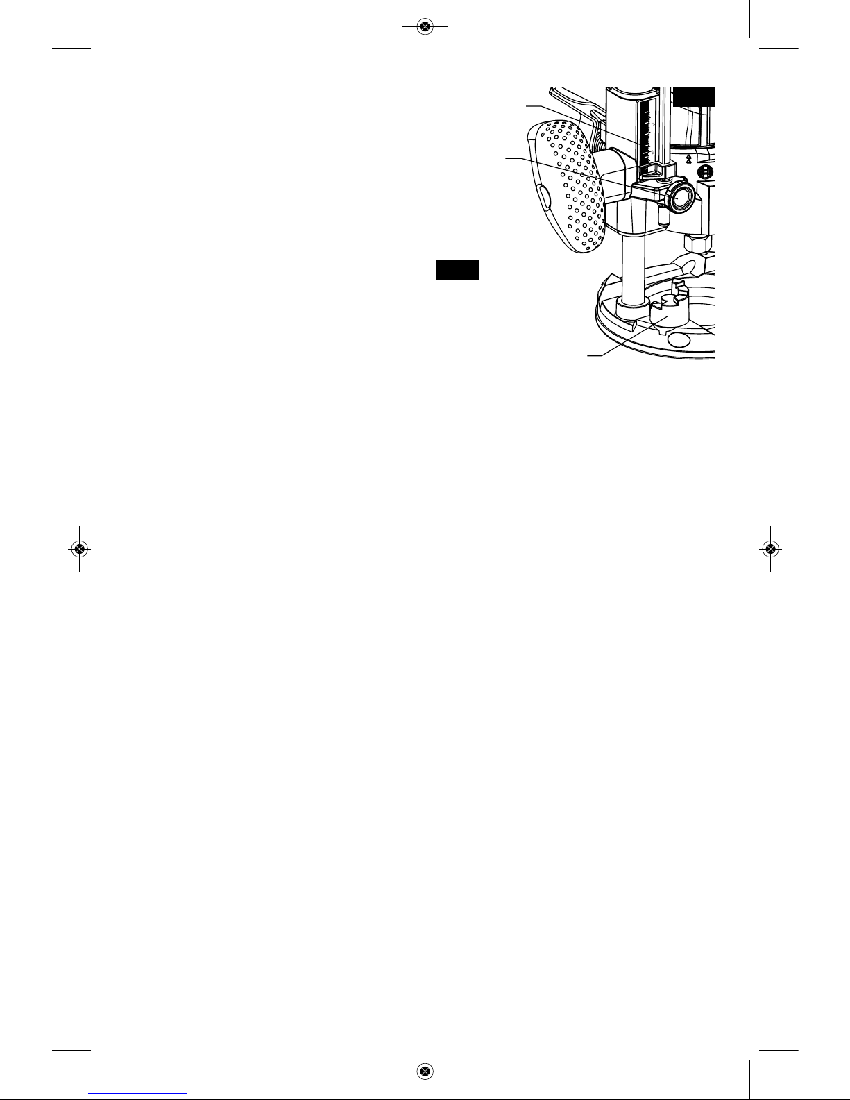
Fixed-Base Palm Router Configuration
MICROFINE DEPTH
ADJUSTMENT
BIT ROTATION ARROW
COLLET NUT
CONTOURED
GRIP AREA
BRUSH CAP
VARIABLE-SPEED DIAL
(PR20EVS MODEL)
FINGER SUPPORT
POCKETS
FINGER GUARDS
POWER CORD
QUICK-CLAMP
SYSTEM LEVER
DEPTH SCALES
(IMPERIAL & METRIC)
SPINDLE LOCK
SUBBASE
RUGGED ALUMINUM
BASE (PR001)
COARSE ADJUSTMENT
UNLOCK/LOCK INDICATOR
ROCKER
ON/OFF
SWITCH
AIR VENTS
FIG. 1
Model Number PR10E PR20EVS
Bit Capacity 1/4" shank 1/4" shank
Max. Cutter Diameter **
* Cutter diameter must be at least 1/4” smaller than opening for
the bit and cutter.
NOTE: For tool specifications refer to the nameplate on your tool.
BM 2610021461 06-12_BM 2610021461 06-12.qxp 6/26/12 1:38 PM Page 7
-8-
Functional Description and Specifications
Dis c o nnect the pl ug from the power sourc e before maki n g any
assembly, adjustments or changing accessories. Such preventive safety
measures reduce the risk of starting the tool accidentally.
!
WARNING
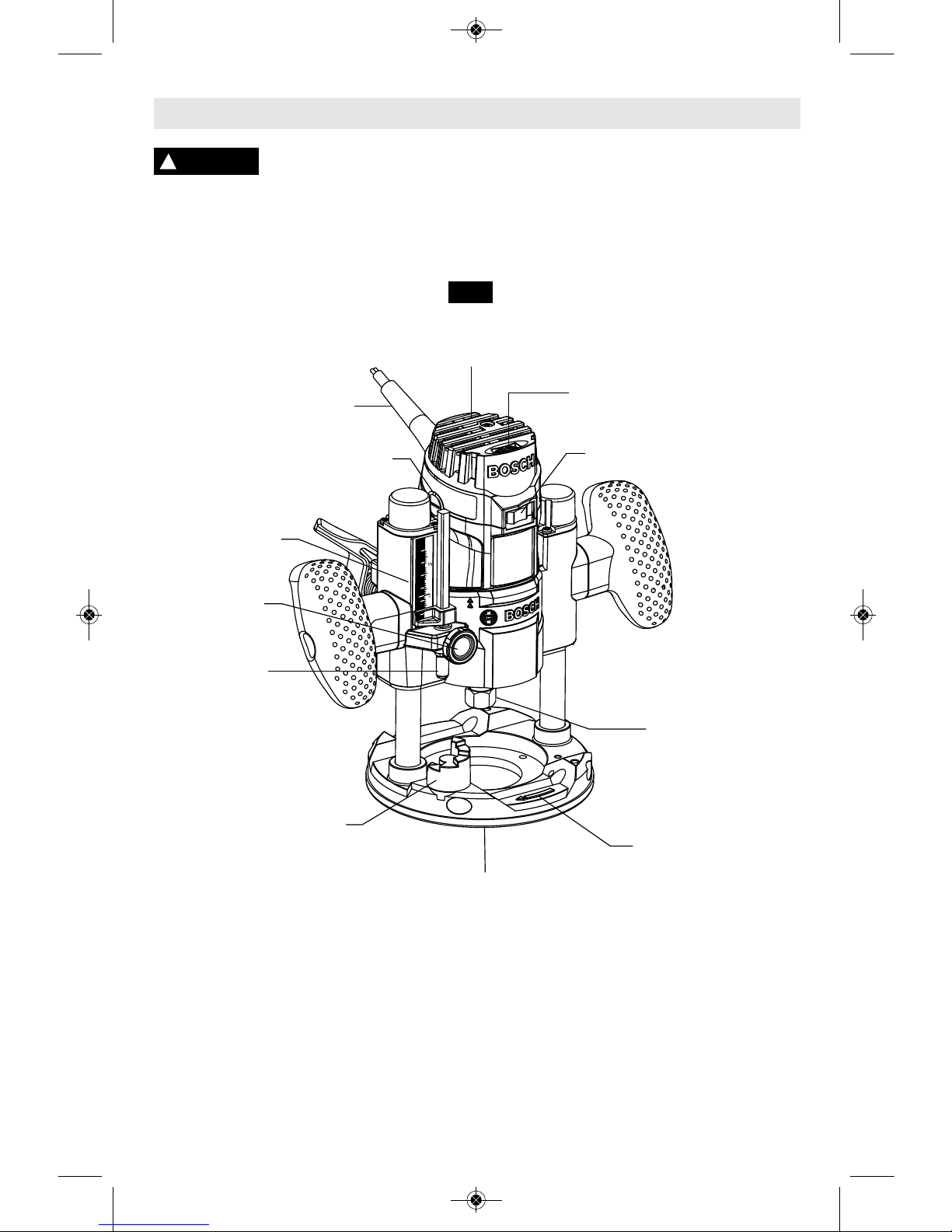
Plunge-Base Palm Router Configuration
FIG. 2
Model Number PR10EP PR20EVSP
Bit Capacity 1/4" shank 1/4" shank
Max. Cutter Diameter **
* Cutter diameter must be at least 1/4” smaller than opening for the
bit and cutter.
NOTE: For tool specifications refer to the nameplate on your tool.
2
1
0
IN
50
40
30
20
10
0
MM
AIR VENTS
POWER CORD
BRUSH CAP
Variable-Speed Dial
(model PR20EVSP only)
ROCKER ON/OFF SWITCH
DEPTH
INDICATOR
DEPTH
INDICATOR
KNOB
DEPTH ROD
FINE
ADJUSTMENT
KNOB
DEPTH STOP
TURRET
COLLET NUT
SUBBASE
BIT ROTATION
ARROW
BM 2610021461 06-12_BM 2610021461 06-12.qxp 6/26/12 1:38 PM Page 8
SELECTING BITS
Your Bosch palm router is designed for a wide
variety of routing applications that use 1/4"
sha nk bits. Thes e include woo d working
applications such as edge forming, grooving,
and sign making. This router is also ideal for
trimming laminates, phenolics, and other
ma t erials that ha v e been bonded to a
substrate overhang the substrate typically by
about 1/8" (3 mm).
A wide assortment of router bits with different
profiles are available as accessories. Only use
good quality bits.
To prevent personal injury,
alw a ys remove the plug
from power source before removing or in stal ling bits or accessories.
Installing a Router Bit *
1. Lay the router or motor on its side (unless
ro u ter i s in the plunge-bas e route r
configuration). The router can also be stood
"on its head" for bit changes, such as when
in the plunge-base configuration.
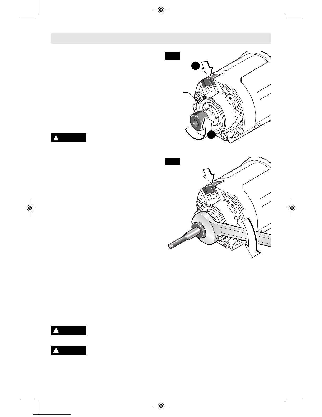
2. Press spindle lock to prevent rotation of
collet chuck. NOTE: it may be necessary to
rotate collet nut to engage spindle lock
(Fig. 3).
3. Next, use the collet wrench to loosen the
collet chuck assembly in a counter-clockwise
direction (viewed from bottom of router).
4. Insert the shank of the router bit into the
collet chuck assembly as far as it will go,
then back the shank out until the cutters are
approximately 1/8" to 1/4" away from the
collet nut face.
5. With the router bit inserted and the spindle
lock engaged, use the collet wrench to firmly
tighten the collet chuck assembly in a
clockwise direction (viewed from bottom of
router) (Fig. 4).
To ensure proper gripping of the router bit and
minimize run-out, the shank of the router bit
must be inserted at least 5/8".
Cutter diameter must be at
le a s t 1/ 4 ” sma l ler th an
opening for the bit and cutter.
To prevent damage to tool,
do not tighten collet without
a bit.
* As an alternative to the spindle lock, the thin
10mm wrench can be used on the ‘flats’ of
the spindle.
NOTE: The bit shank and chuck should be
clean and free of dust, wood, residue and
grease before assembling.
Removing the Router Bit*
1. Press spindle lock to prevent rotation of
collet chuck, and turn the collet chuck
assembly in a counter-clockwise direction.
2. Once the collet chuck assembly is loosened,
continue to turn the collet chuck assembly
until it pulls the collet free from the spindle,
and the router bit can be removed.
NOTE: The collet chuck is self-extracting; it is
NOT necessary to strike the collet chuck to
free the router bit.
-9-
Assembly
!
WARNING
2
1
FIG. 3
FIG. 4
!
WARNING
SPINDLE
FLATS
!
CAUTION
SPINDLE LOCK
SPINDLE LOCK
(BASE REMOVED FOR CLARITY)
BM 2610021461 06-12_BM 2610021461 06-12.qxp 6/26/12 1:38 PM Page 9
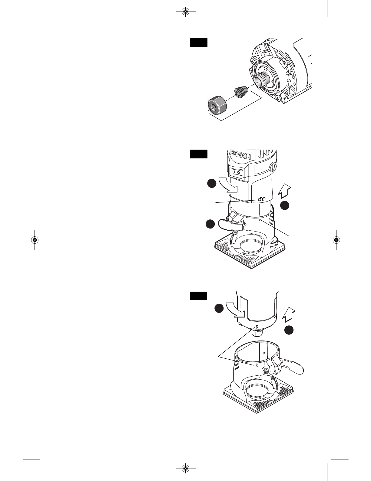
COLLET CHUCK CARE
With the router bit removed, continue to turn
the collet chuck counter-clockwise until it is
fr e e of th e shaft. To assu re a fi rm grip,
occasionally blow out the collet chuck with
compressed air, and clean the taper in the
armature assembly shaft with a tissue or fine
brush. The collet chuck is made up of two
component parts that snap together (Fig. 5);
check to see that the collet is properly seated
in the collet chuck nut and lightly thread the
collet chuck back onto the armature shaft.
Replace worn or damaged collet chucks
immediately.
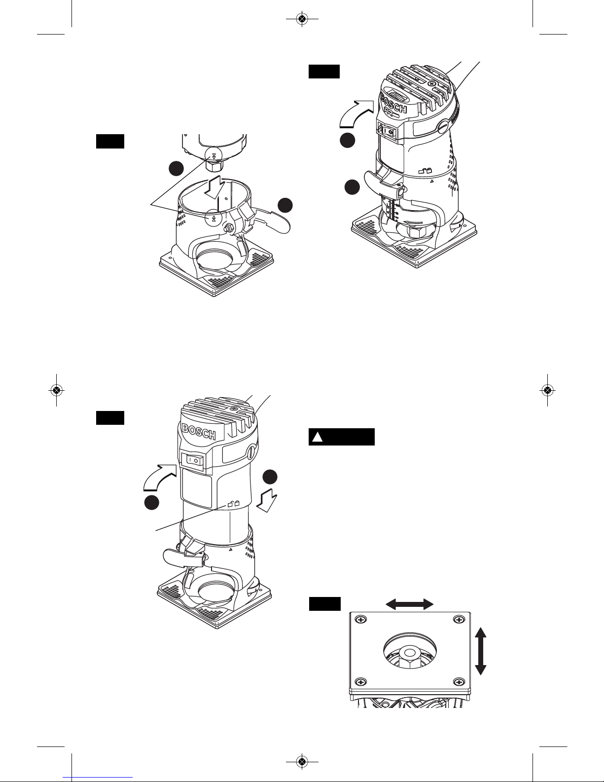
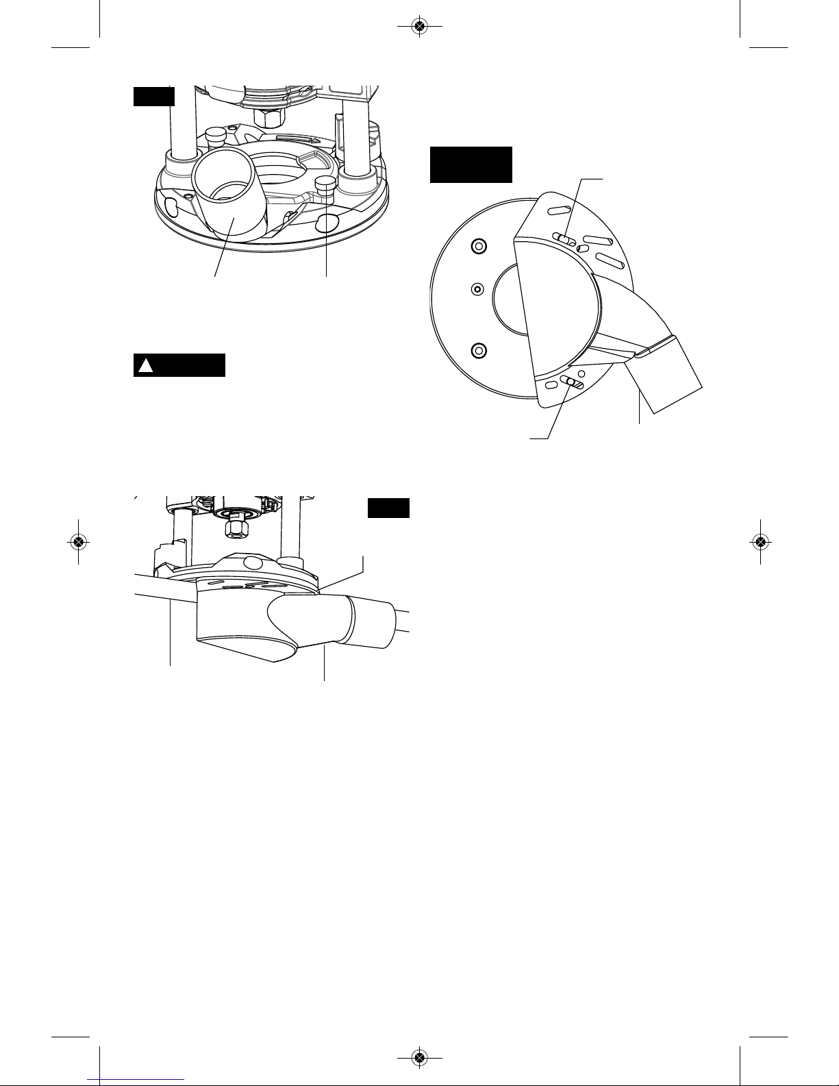
REMOVING MOTOR FROM BASE
1. Open the clamping lever (Fig. 6).
2. Turn the motor so that the single triangle on
the base lines up with “unlocked” symbol on
th e motor. (Make sur e that t he single
triangle the base is aligned with the line
under the “unlocked” symbol on the motor.
Otherwise, the router can be damaged.)
(Fig. 6)
3. Pull the motor away from base until it stops
(Fig. 6).
4. Turn motor counterclockwise until it stops
(Fig. 7).
5. Pull motor out of base (Fig. 7).
-10-
2
1
3
COLLET
COLLET
CHUCK
NUT
FIG. 5
FIG. 6
1
5
4
FIG. 7
SINGLE
TRIANGLE
UNLOCKED
SYMBOL
DOUBLE
TRIANGLES
BM 2610021461 06-12_BM 2610021461 06-12.qxp 6/26/12 1:38 PM Page 10
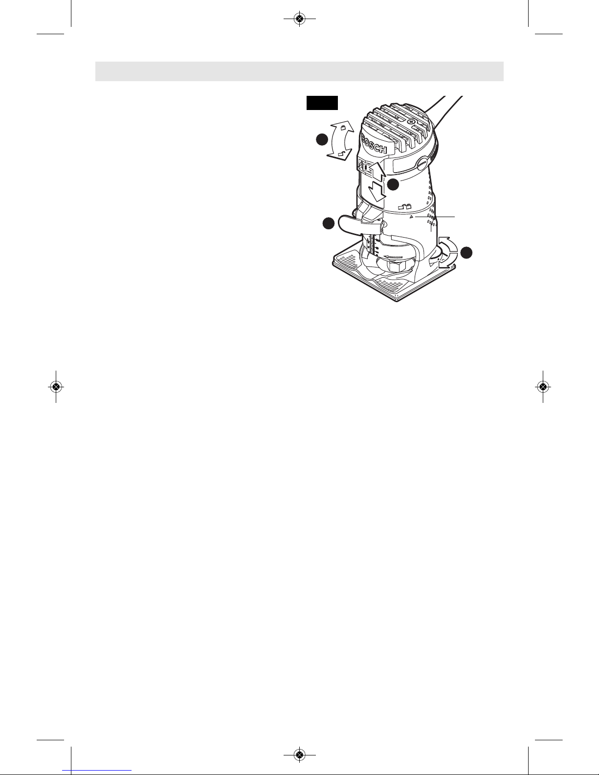
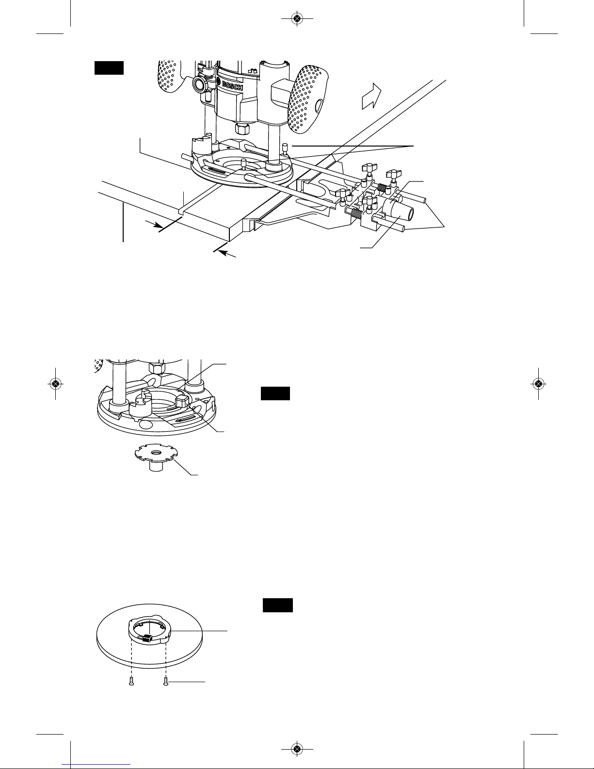
INSTALLING THE MOTOR INTO
PR001 FIXED BASE
1. Open the clamping lever (Fig. 8).
2. Align the double triangles on the base and
motor then insert motor into base until it
stops (Fig. 8).
3. Turn motor clockwise until single triangle
lines up with “unlocked” symbol. (Make sure
that the indication the base is aligned with
the line under the “unlocked” symbol on the
mo t or. Otherwise , the router can b e
damaged.) (Fig. 9)
4. Move motor into base until the approximate
desired depth has been reached. (Fig. 9)
5. Turn motor clockwise about 1/4” until single
triangle lines up with “locked” symbol. (Fig. 10)
6. Close the clamping lever. Always make sure
the motor sits tightly in the base. (The
te n sion of the clamping lever can be
changed by re-adjusting the nut.) (Fig. 10)
CHECK SUBBASE LOCATION
Make sure that the bit and its cutter are
centered in the subbase opening. If necessary,
adjust the location of the subbase as follows:
1. Loosen the four screws that hold the subbase.
2. Adjus t the location of the subbase as
needed so that the bit and its cutter are
centered in the subbase opening. The
optional RA1151 centering device makes
this easy.
3. Tighte n the four scr ews that hold the
subbase (Fig. 11).
Cutter diameter must be at
le a s t 1/4” smaller than
opening for the bit and cutter.
When the subbase has been centered in this
ma n ner, the left and right edges of the
subbase are equidistant from the cutter, and
either side of the subbase can be used as a
guiding surface without worrying about a
difference in the cut line. See "Guiding The
Router" on page 13.
Note: This subbase is not designed for use
with templet guides. See optional PR009 and
PR010 Accessories for use of templet guides
with the palm router.
-11-
4
3
FIG. 9
1
2
FIG. 8
!
WARNING
FIG. 11
5
6
FIG. 10
DOUBLE
TRIANGLES
UNLOCKED
SYMBOL
BM 2610021461 06-12_BM 2610021461 06-12.qxp 6/26/12 1:38 PM Page 11
Bos ch routers are designed fo r sp eed,
accuracy and con venience in performing
cabinet work, fluting, beading, cove-cutting,
rounding edges, dovetailing, etc. They will
ena ble you to ac complish inlay work,
decorative edges and many types of special
routing.
SETTING THE DEPTH OF CUT
Adjust the depth-of-cut only when the motor is
switched off.
1. Install desired router bit.
2. Place the router on the workpiece.
3. Open the clamping lever. Fig. 12(A)
4. Turn the motor about 1/4” counter-clockwise
so that the single triangle on the base lines
up with “unlocked” symbol on the motor. Fig.
12(B) (Make sure that the single triangle in
the base is aligned with the line under the
“unlocked” symbol on the motor. Otherwise,
the router can be damaged.)
5. Slowly lower the motor until the router bit
touches the workpiece. Fig. 12(C)
6. Note the reading on the scale (below the
clamp lever) and add the desired depth-ofcut to this value to determine the target
scale value.
7. Lower the motor until the target scale value
is reached. Fig. 12(C)
8. Turn motor clockwise about 1/4” until single
triangle lines up with “locked” symbol. Fig.
12(B)
9. Close the clamping lever. Always make sure
th e motor is held tightly in the base.
Fig. 12(A) (The tension of the clamping lever
can be changed by re-adjusting the nut.)
10. Check the depth-of-cut and make fine
adjustment if necessary. (Note: the depth
of the motor and bit may shift very slightly
when the clamping lever is closed D)
11. Make a trial cut to verify that the router is
set to make the cut as desired.
FINE DEPTH ADJUSTMENT
Adjust the depth-of-cut only when the motor is
switched off.
1. Open the clamping lever. Fig. 12(A)
2. Adjust the desired depth-of-cut with the
knurled wheel on back of base. Fig. 12(D)
3. Rotate the knurled wheel clockwise to
increase the routing depth, counterclockwise
to d ecrease the cu t ting depth. Ea c h
complete rotation of the dial equals 1.25 mm
(approximately 3/64").
4. Close the clamping lever. Fig. 12(A) Always
make sure the motor is held tightly in the
base. Re-adjusting the nut can change the
tension of the clamping lever. (See “To
Clamp Motor”, below)
5. Check the depth-of-c ut and make an
additional fine adjustment if necessary.
(Note: the depth of the motor and bit may
shift very slightly when the clamping lever is
closed.)
6. Make a trial cut to verify that the router is set
to make the cut as desired.
TO CLAMP MOTOR
When final macro and fine adjustments have
been made, fasten the base clamp lever to
secure adjustments. (If additional clamping
force is desired: using a 8 mm wrench, rotate
clamp nut clockwise SLIGHTLY (1/8 turn or
less), then test clamp. Do not over-tighten.)
DEEP CUTS
For deep cuts, make several progressively
deeper cuts by starting at one depth and then
make several subsequent passes, increasing
the cutting depth with each pass.
To be certain that your depth settings are as
desired, you may want to make test cuts in
scrap material before beginning work.
-12-
C
A
D
B
Operating Instructions
FIG. 12
SINGLE
TRIANGLE
BM 2610021461 06-12_BM 2610021461 06-12.qxp 6/26/12 1:38 PM Page 12
-13-
ROCKER “ON/OFF” SWITCH
Your tool can be turned “ON” or “OFF” by the
rocker switch located on the motor housing.
One side of the switch is marked “I” for “ON“,
and the other side of switch is marked “O” for
“OFF“.
TO TURN THE TOOL “ON”: Push the side of
the switch marked “I”.
TO TURN THE TOOL “OFF”: Push the side
of the switch marked “O”.
SOFT START FEATURE
Electronic feedback control minimizes torque
twist customary in routers by limiting the speed
at which motor starts.
ELECTRONIC VARIABLE SPEED
CONTROL
(Model PR20EVS Only)
The electronic speed control feature allows
motor speed to be matched to cutter size and
ma t erial h ardness for i mproved finish,
extended bit life, and higher performance.
Speed changes are achieved by rotating the
Control Dial RIGHT to increase speed or LEFT
to decrease as indicated on housing (Fig. 1).
Speed may be changed while tool is on. The
reference numbers on the dial facilitate resetting control to desired speed.
The speed chart indicates the relationship
be tween s ettings and applicati on, ex act
settings are determined by operator experience
and preference. The bit manufacturer may also
have a speed recommendation.
CONSTANT RESPONSE™ CIRCUITRY
The router's Constant Response™ Circuitry
monitors and adjusts power to maintain the
desired RPM for consistent performance and
control.
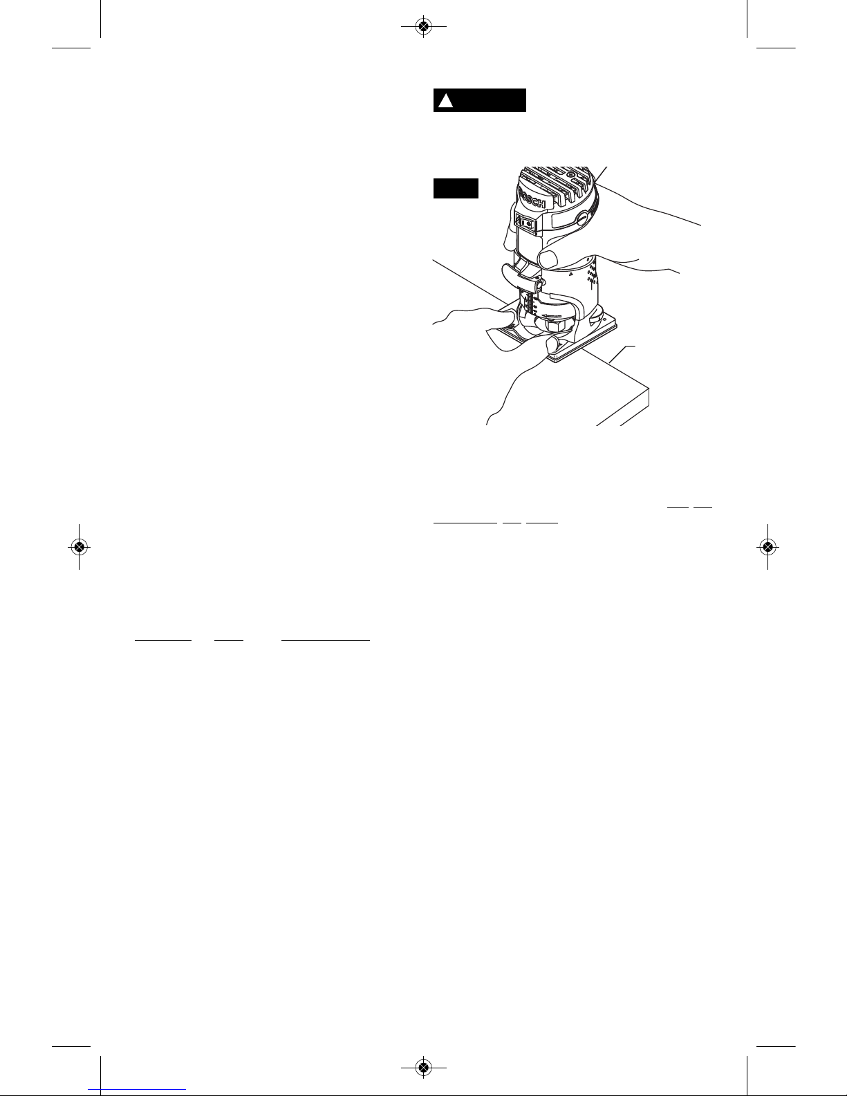
FEEDING THE ROUTER
In addition to the main palm-grip area at the
back of the motor housing and base, the base
has Bosch-exclusive finger support pockets to
provide additional stability for the router. The
pockets feature finger guards to provide a
barrier between the finger pockets and the bit
area (Fig 13).
When using finger pockets,
alw ays place both finger
pockets over the workpiece and always hold
the router in a way that allows you to see your
finger and thumb.
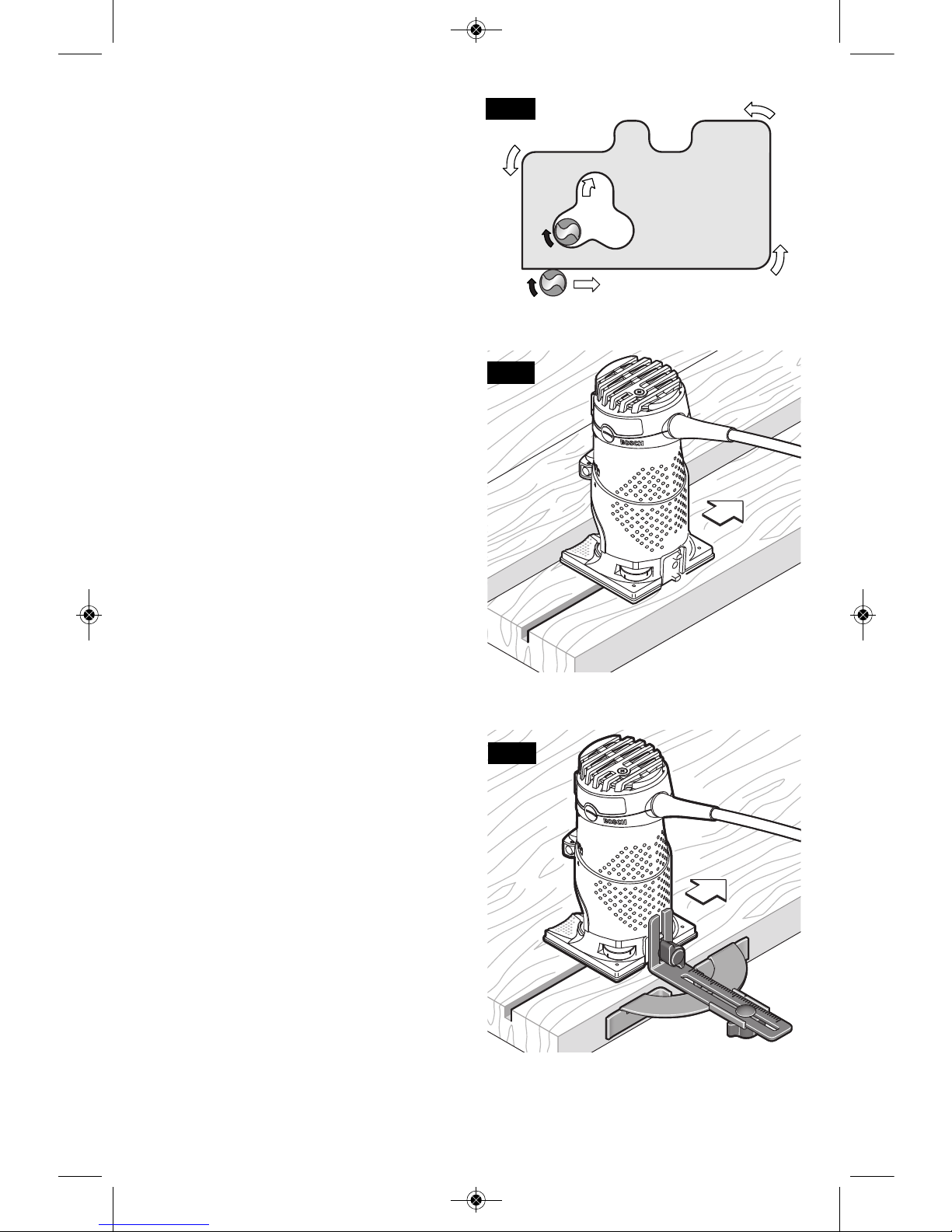
As seen from the top of the router, the bit turns
clockwise and the bit’s cutting edges are
positioned to best cut into the workpiece.
Therefore, the most efficient cut is made by
feeding the router so that the bit turns into
the
workpiece, not away. Figure 14 shows proper
feed for various cuts. How fast you feed
depends on the hardness of the material and
the size of the cut. For some materials, it is
best to make several cuts of increasing depth.
If the router is hard to control, heats up, runs
ver y slowly or l eaves an imperf e ct cut,
consider these causes:
1. Wrong direction of feed — hard to control.
2. Feeding too fast — overloads motor.
3. Dull bit — overloads motor.
4. Cut is too large for one pass — overloads
motor.
5. Feeding too slow — leaves friction burns on
work.
Feed smoothly and steadily (do not force). You
will soon learn how the router sounds and feels
when it is working best.
Always hold the router off the work when
turning the switch on or off. Contact the work
with the router after the router has reached full
speed, and remove it from the work before
turning the switch off. Operating in this manner
will prolong switch and motor life and will
greatly increase the quality of your work.
DIAL
SETTING RPM APPLICATION
1 16000
2 18000
3 20000
4 22500
5 26500
6 35000
}
}
Larger-diameter bits
and cutters.
Softwoods, plastics,
laminates, smaller
diameter bits and
cutters
FIG. 13
WORKPIECE
WORKPIECE
EDGE
!
WARNING
BM 2610021461 06-12_BM 2610021461 06-12.qxp 6/26/12 1:38 PM Page 13
-14-
RATE OF FEED
When routing or doing related work in wood
and plastics, the best finishes will result if the
depth of cut and feed rate are regulated to
keep the motor operating at high speed. Feed
the router at a moderate rate. Soft materials
require a faster feed rate than hard materials.
The router may stall if improperly used or
overloaded. Reduce the feed rate to prevent
possible damage to the tool. Always be sure
the collet chuck is tightened securely before
use. Always use router bits with the shortest
cutting length necessary to pr oduce the
desired cut. This will minimize router bit run-out
and chatter.
It may be necessary to make the cut in more
than one pass with progressively deeper
settings to avoid overloading the motor. If the
bit cuts freely and the motor does not slow
down, the cutting depth is generally correct.
GUIDING THE ROUTER
The router can be guided through the work in
any of several ways. The method you use
depends, of course, on the demands of the
particular job and on convenience.
For routing operations such as grooving or
dadoing, it is often necessary to guide the tool
in a line parallel to a straight edge. One
method of obtaining a straight cut is to securely
clamp a board or other straightedge to the
work surface, and guide the edge of the router
sub-base along this path (Fig. 15).
PR002 STRAIGHT ROUTER GUIDE
(Included with PR20EVSK & PR20EVSNK,
also available as optional accessory)
The router guide is an optional accessory that
will guide the router parallel to a straight edge
(Fig. 16).
The router guide is supplied in two parts held
together with a bolt, wing nut and washer. It
also includes a wing screw and washer to
fasten the guide to the router.
The guide features a scale for accurately
positioning the edge guide relative to the bit.
With the guide installed and adjusted, the
router should be fed normally, keeping the
guide in contact with the edge of the workpiece
at all times.
The router guide can also be positioned
directly under the router base for operations
where a cut is needed close to or at the edge
of the work, such as when rounding off deck
planks.
FIG. 16
FIG. 15
FIG. 14
WORKPIECE
DIRECTION OF ROUTER FEED
BM 2610021461 06-12_BM 2610021461 06-12.qxp 6/26/12 1:38 PM Page 14
-15-
USING SELF-PILOTED BITS
Self-piloted bits have an integral round tip or
ball bearing which rides against the work
surface above or below the cutter to control
horizontal cutting depth (Fig. 17). When using
these bits, neither the roller guide or the
straight guide is required. When guiding
against a laminated surface, use wax or other
lubricant and do not apply excess pressure or
the piloted end may mar the work. Bearing
pilots must be kept clean and free of adhesive
or other residue. Router bit bearings are
sealed and permanently lubricated, and should
be replaced when they no longer turn freely to
avoid damaging the work surface.
PR003 ROLLER/BUSHING GUIDE
(Included with PR20EVSNK, also available as
optional accessory)
The optional PR003 Roller/Bushing Guide is
used when edge-forming or trimming with
unpiloted bits, non-bearing bits.
Attachment of Roller/Bushing Guide
The PR003 roller/bushing guide (Fig. 18) is
attached using the wing screw and washer.
Adjustment of Roller/Bushing Guide
Vertical Adjustment:
1. Loosen the wing screw and adjust up or
down as necessary to allow roller/bushing to
ride on the intended guiding surface.
2. Tighten wing screw.
Horizontal Adjustment:
Whether making straight or bevel cuts, the
width of material removed is determined by the
distance between the front of the router bit’s
cutter and the front of the roller/bushing. Adjust
the front of the roller/bushing as follows:
1. Loosen wing nut at bottom.
2. Rotate the wing nut on the back of the guide
to move the roller/bushing in or out to create
amount of cutter exposure needed to trim
the laminate flush with the guiding surface or
to create the desired bevel.
3. Be sure th e bit clears the top of the
roller/bushing guide by at least 1/8" (3 mm)
to avoid damage.
4. Tighten wing nut on the bottom of the guide
assembly
5. Make a trial cut to check the setting and
readjust as necessary.
Use of the Roller/Bushing Guide
1. With the guide installed and adjusted, the
router should be fed normally, keeping the
gui de in contact with the edge of the
workpiece at all times.
2. To maintain a consistent width of cut, a
con sistent angle must be maintain e d
between the router and the workpiece.
FIG. 17
FIG. 18
BM 2610021461 06-12_BM 2610021461 06-12.qxp 6/26/12 1:38 PM Page 15
PR009 AND PR010 ROUND SUBBASES &
USE OF TEMPLET GUIDE BUSHINGS WITH
PR001 FIXED BASE
(Available as optional accessories)
Optional large round subbases are available
separately and allow various templet guide
bushings to be used with the palm routers.
Templet guide bushings are used to guide the
router to repeatedly make consistent openings
and inlays using various templets (also referred to
as patterns and jigs). Templets for standard
routing applications are available commercially,
such as the Bosch hinge templet kit; and templets
for specialty applications are typically made by
users for their specific needs.
The PR009 Round Subbase accepts the Bosch
RA-Series Templet Guide Adapters.
The PR010 Round Subbase accepts threaded
templet guide adapters.*
*Note: The RA1100 Adapter for Threaded
Templets allows use of conventional threaded
templet guides with the PR009 Round Subbase.
PR009 Attachment of Templet Guide and
Round Subbase (Fig. 19)
1. Remove regular subbase.
2. Insert templet guide into top of round subbase
such that the anti-rotation stops in the subbase
fit into the corresponding places in the templet
guide. (When using the RA1100 adapter, first
place the rubber O-ring between the antirotation stops and the subbase.) (Fig. 20).
3. Loosely attach round subbase using panhead
screws that come with that accessory.
4. Center the templet guide around the bit. (The
optional Bosch RA1150 Centering Cone can
be used to ensure that the templet guide is
properly centered.)**
5. Tighten the panhead screws to hold the
templet guide and subbase in position.
Note: If a templet guide seems loose, repeat
steps 2- 5 after adding the rubber O-ring.
PR010 Attachment Round Subbase of
Threaded Templet Guide (Fig. 21)
1. Remove regular subbase.
2. Loosely attach round subbase using panhead
screws that come with that accessory.
3. Attach the threaded templet guide by putting
the templet guide through the bottom and
attaching the ring from the top.
4. Center the templet guide around the bit. (The
optional Bosch RA1151 Centering device can
be used to ensure that the templet guide is
properly centered.)**
5. Tighten the panhead screws to hold the
templet guide and subbase in position.
Creating Templets
Templet patterns can be made of plywood,
hardboard, metal or even plastic. The design can
be cut with a router, jigsaw, or other suitable
cutting tool. Remember that the pattern will have
to be made to compensate for the distance
between the router bit and the templet guide (the
“offset”), as the final workpiece will differ in size
from the templet pattern by that amount, due to
the bit position (Fig. 22).
*See page 26 for available templet guide sizes.
**See page 25 for details about centering.
-16-
WORKPIECE
ROUTER BIT
OFFSET
TEMPLET
GUIDE
TEMPLET
PATTERN
ROUTER
SUBBASE
FIG. 21
FIG. 22
PR010 SUBBASE
TEMPLET GUIDE
RING
ROUTER BASE
PANHEAD
SCREWS
TEMPLET
GUIDE
FIG. 19
ROUTER
BASE
PANHEAD
SCREWS
TEMPLET
GUIDE
PR009 SUBBASE
RUBBER O-RING
(If necessary)
FIG. 20
RUBBER O-RING
(If necessary)
ANTI-
ROTATION
STOPS
ANTI-
ROTATION
STOPS
COLLET CHUCK
BM 2610021461 06-12_BM 2610021461 06-12.qxp 6/26/12 1:38 PM Page 16
-17-
PR004 OFFSET BASE
(Included with PR20EVSNK. Also available as
optional accessory)
The PR004 Offset Base is designed for routing
in confined areas, especially for trimming
laminates in areas that are inaccessible with
the standard fixed base, such as locations that
are close to adjacent vertical surfaces like as
the tops of already-installed counter backsplash
backsplashes (Fig. 23).
The PR004 allows routing extremely close to
vertical surface in front of the tool, as close as
1/2” when 3/4” bit is used (Removal of the black
offset spindle cover further reduces distance
from 3/4” bit and vertical surface to 3/8”.) The
1-1/16” base opening makes it possible to use
bits that have cutters as wide 13/16”.
The PR004 can also be used to scribe the back
of a new counter backsplash so that it will mate
precisely with the wall against which it will rest
(Fig. 24).
Heat Build-Up
To reduce the risk of injury,
do not use the offset base
for more than 10 minutes continuously.
Prolonged continuous use will result in the tool
becoming hot to the touch.
The nature of a belt drive mechanism like the
one in the PR004 Offset Base creates more
heat than when the motor is used in its other
bases. To help minimize heat build-up, the
PR004 has been designed with large bearings,
specially-designed heat sinks, carefully-directed
airflow and plastic heat shields. Depending on
the application, the PR004 Offset Base can be
used for up to about 10 minutes continuously
before it will need to be left idle so that it can
cool off.
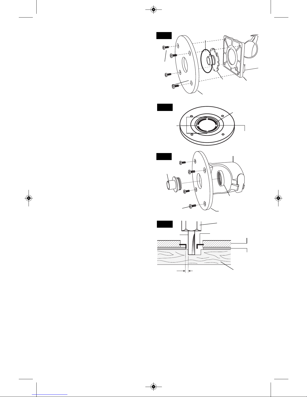
Motor Installation
1. Remove collet from motor and install toothed
drive pulley using collet wrench. Make sure
that drive gear is fully tightened onto the
motor’s spindle. (Fig. 25)
2. The motor is then installed into the base
according to the instructions on page 9.
3. Insert screwdriver (not included) through the
U-shaped opening in the subbase to fit belt
over drive pulley. (Fig. 26)
FIG. 26
!
WARNING
FIG. 23
FIG. 24
FIG. 25
DRIVE GEAR
BM 2610021461 06-12_BM 2610021461 06-12.qxp 6/26/12 1:38 PM Page 17
Installation of Bit
1. Insert bit to the desired depth as per the
instructions on page 9.
2. Press large red spindle lock button on top of
offset spindle (Fig. 27).
3. Tighten collet nut using the same collet
wrench as is used on the motor’s own collet
nut. (The collet used on the PR004 is the
same type of self-releasing collet used on
the motor itself when used with the other
bases.)
4. Make a trial cut to check the depth and
readjust as necessary.
Using the Offset Router
The principles of using the offset router are
basically the same as for the fixed-base router
set-up (motor in fixed-base assembly), with the
following differences
1. The offset router should be gripped with one
hand gripping the motor gripping area and
the other hand gripping the back of the base
housing (Fig. 23) or gripping the top of the
offset spindle.
2. For routing backsplashes and other elevated
workpieces, some installers mount the offset
base to a wood block that matches the
height of the laminated backsplash. This
hel ps to maint ain a consis tent angle
between the bit’s cutter and the workpiece
and to provide addition stability.
Offset Base Roller/Bushing Guide
The PR004’s roller/bushing guide is required
when edge-forming or trimming with unpiloted
non-bearing bits.
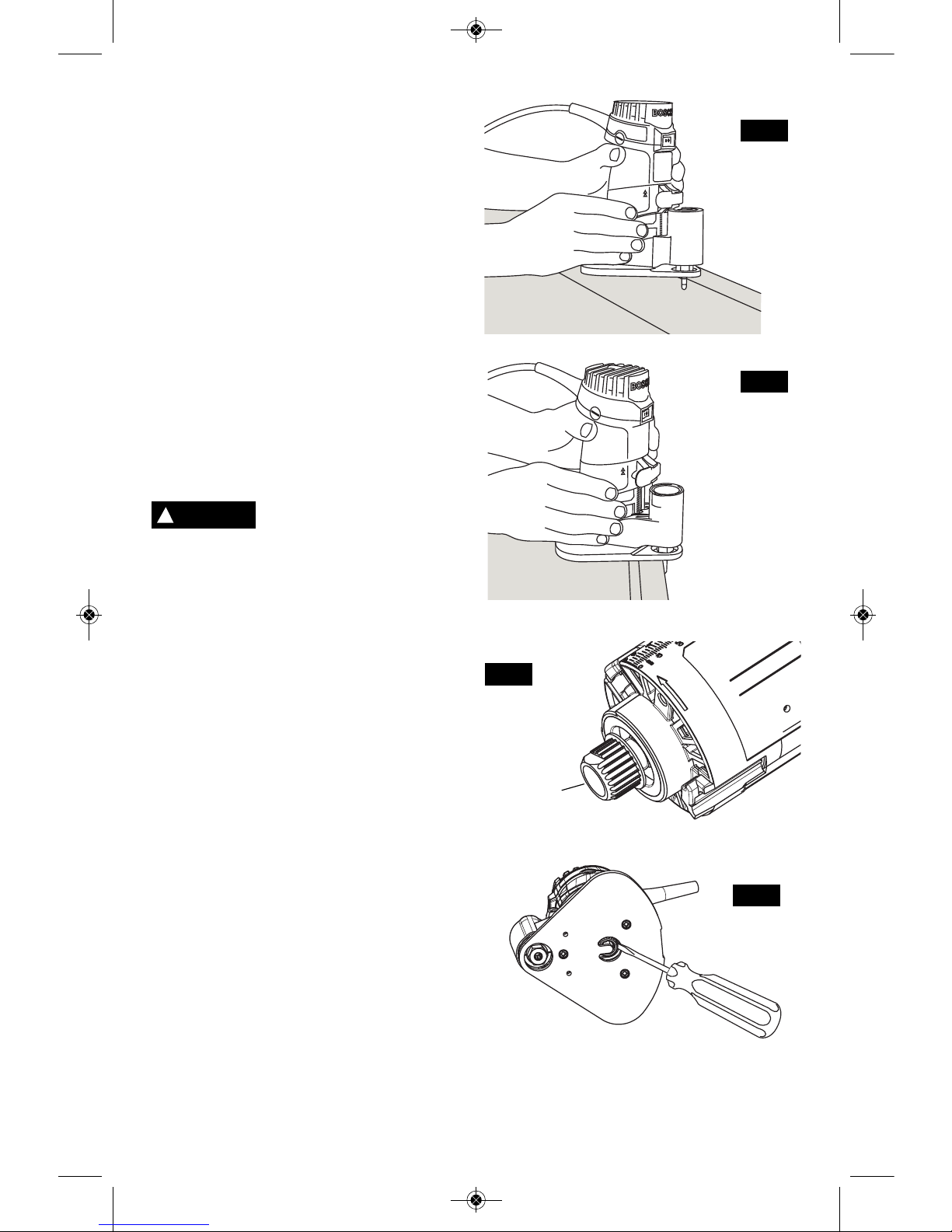
Attachment of Roller/Bushing Guide
The PR004’s roller/bushing guide is attached
using two screws with a Philips screwdriver
(not included). Fig. 28
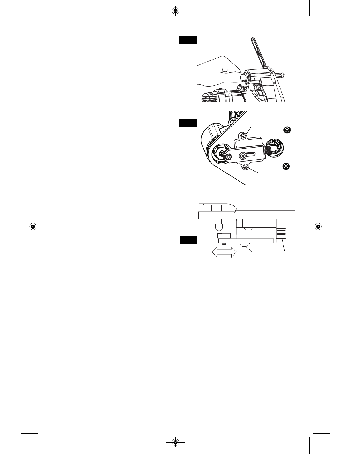
Adjustment of Roller/Bushing Guide
Whether making straight or bevel cuts, the
width of material removed is determined by the
distance between the front of the router bit’s
cutter and the front of the roller/bushing. Adjust
the front of the roller/bushing as follows
(Fig. 29):
1. Using a Phillips screwdriver, to adjust,
loosen screw.
2. Rotate the knurled knob on back of the
guide to move the roller/bushing in or out to
create amount of cutter exposure needed to
trim the laminate flush with the guiding
surface or to create the desired bevel.
3. Be sure th e bit clears the top of the
roller/bushing guide by at least 1/8" (3 mm)
to avoid damage.
4. Tighten clamping screw using a Phillips
screwdriver.
5. Make a trial cut to check the setting and
readjust as necessary.
Use of the PR004 with
Roller/Bushing Guide
1. With the guide installed and adjusted, the
router should be fed normally, keeping the
gui de in contact with the edge of the
workpiece at all times.
2. To maintain a consistent width of cut, a
con sistent angle must be maintain e d
between the router and the workpiece.
-18-
FIG. 27
FIG. 28
FIG. 29
MOUNTING
SCREW
MOUNTING
SCREW
CLAMPING
SCREW
KNURLED
KNOB
BM 2610021461 06-12_BM 2610021461 06-12.qxp 6/26/12 1:38 PM Page 18
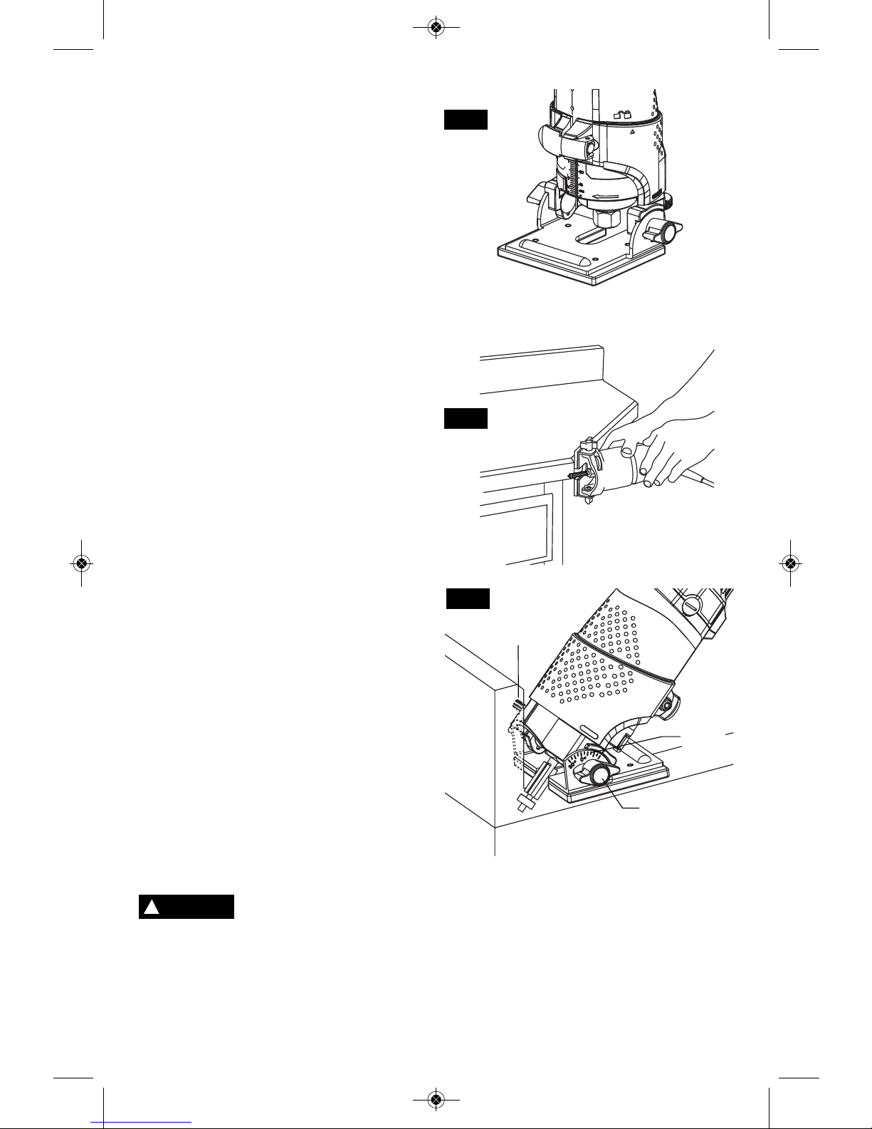
PR005 TILT BASE
(Included with PR20EVSNK. Also available as
optional accessory)
The PR005 Tilt Base (Fig. 30) is used for the
following purposes:
• Trimming laminated edges at the point that
they reach adjacent vertical surface, such as
a kitchen counter’s backsplash (Fig. 32).
• Trimming special angles (Fig. 31)
• Making bevel cuts. One method of obtaining
a consistent bevel cut is to securely clamp a
board or other straightedge to the work
surface, and guide the edge of the router
subbase along this path (Fig. 15).
Motor Installation
Th e motor is installed accordin g to the
instructions on page 9.
Angle Adjustment
The total tilt range is 75°, from 45° forward to
30° backward.
To adjust the angle (Fig. 32):
1. Loosen the two wing screws.
2. Adjust the angle as desired using the scale
on the left side of the base. Note that there
are de t ents at every 7.5°. Wheneve r
possible, the base should be positioned with
the motor tilted toward the closed end of the
base.
3. Tighten the wing screws. Be careful not to
over-tighten, or the base may be damaged.
Depth Adjustment
Th e depth is adjusted according to the
instructions on page 12.
Using the Tilt Router
The principles of using the tilt router are
basically the same as for the regular router setup (motor in fixed-base assembly), with the
following difference.
1. The PR005 should always be used with a
self-piloted or bearing bit.
2. The proper grip position depends on the
angle of the cut and the tool. The router
should be gripped with one hand gripping
th e motor and t he other grip p ing the
elsewhere on the back of the tool.
To reduce the risk of injury,
never grip the base directly
above or next to the exposed bit.
3. When trimming edges while the bit is tilted
toward the direction of feed, it is extremely
important to keep the base square with the
surface to be routed. If the tilt router is
shifted in the direction of the surface it is
riding on, the upper part of the cutter can dig
far into the workpiece.
-19-
FIG. 30
FIG. 31
FIG. 32
WING SCREW
SCALE
WING
SCREW
!
WARNING
BM 2610021461 06-12_BM 2610021461 06-12.qxp 6/26/12 1:38 PM Page 19
-20-
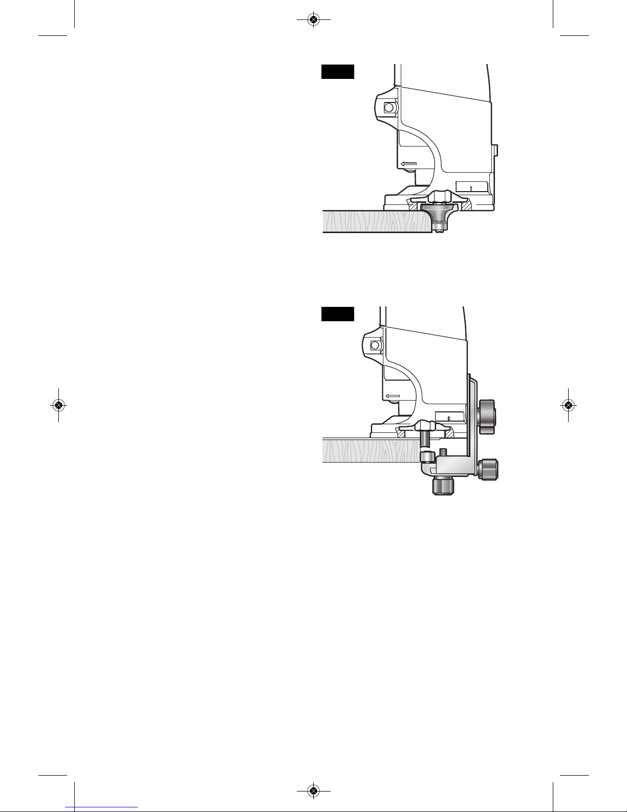
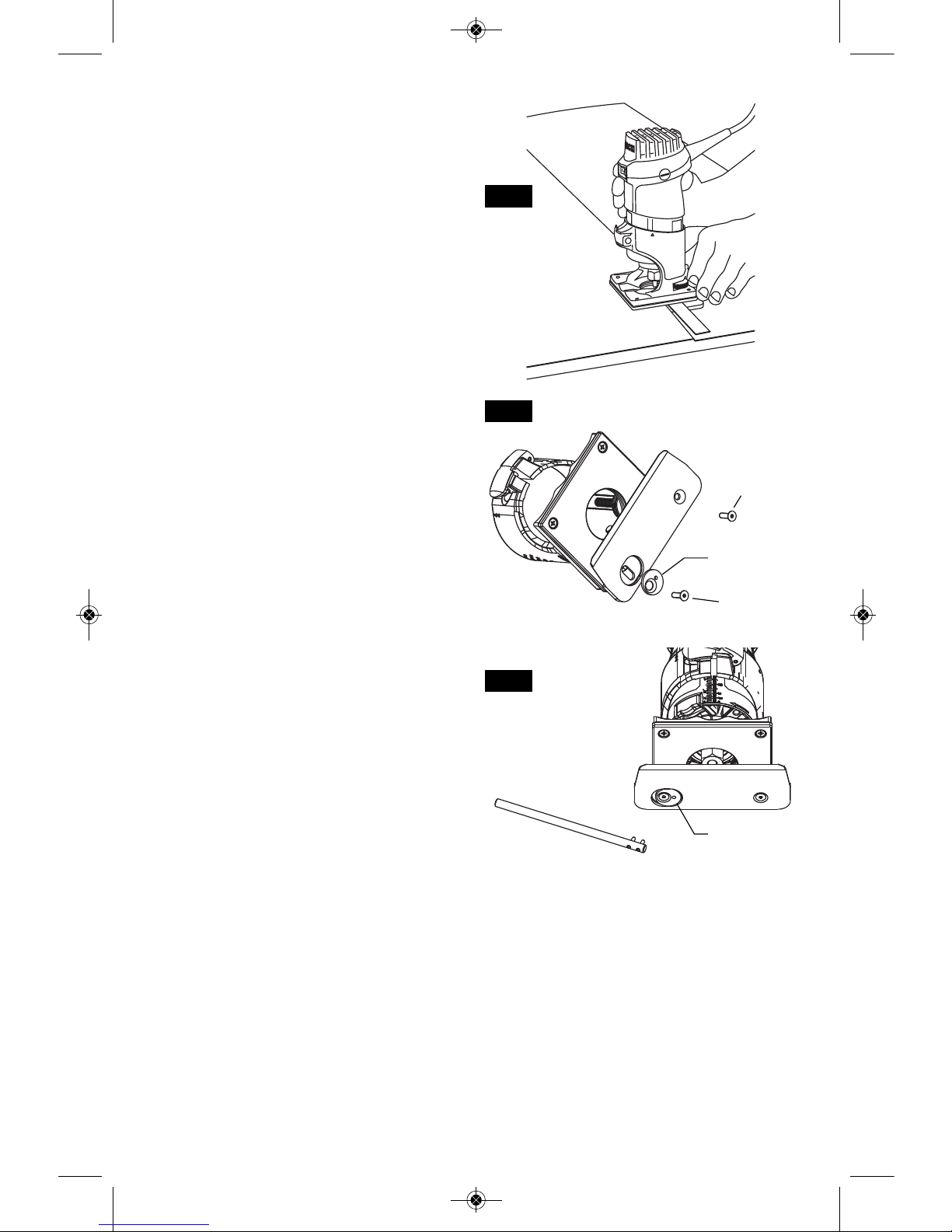
PR006 UNDERSCRIBE ATTACHMENT
(Included with PR20EVSNK. Also available as
optional accessory)
The PR006 Underscribe Attachment is used to
create precision-fit seams between two sheets
of laminate (Fig. 33), such as stile and rail
constructions and very large surfaces. It is
attached to the bottom of the PR001 Fixed
Base or PR011 Plunge Base. See PR011
Plunge Base for use of PR006 with that base.
Installation (Fig. 34)
1. Remove rear screws used to hold subbase
onto PR001 Fixed Base.
2. Attach infeed side of PR006 to the Fixed
Base using hex screw*
3. Insert eccentric adjuster into pocket on
outfeed side of PR006.
4. Attach outfeed side of PR006 to the Fixed
Base using hex screw*
*When used with PR007 Side-Handle Base,
the longer set of attachment screws should be
used.
Bit Installation
• The recomme nd bit for use with the
Und erscribe Atta c hment is the Bo s ch
85213M with 1/8” cutting diameter.
• It should be installed according to the
instructions on page 9.
Bit Height Adjustment
After installing the bit, the height should be
adjusted as follows:
1. Lower bit until it just enters the recess that is
machined in the underscribe attachment’s
aluminum plate.
2. The tool is now ready for making a test cut.
Front-to-Back Adjustment
If necessary, the cutting point can be adjusted
front-to-back as follows (Fig. 35):
1. Loosen the two screws hold ing the
aluminum plate.
2. Using the pin wrench, adjust the eccentric
adjuster as follows:
• For a tighte r seam , turn the eccentri c
adjuster clockwise (as viewed from under
the base)
• For a l o oser seam , turn t he eccent ric
adjuster counterclockwise, (as viewed from
under the base)
3. Retighten the screws
4. Make a test cut
5. Repeat steps 1-4 as necessary
Creating a Seam
1. To create a precision seam, make sure he
guiding piece of laminate has a clean,
straight edge, because it will serve as the
guide for the underscribe attachment.
2. Contact cement should be applied to the
substrate core material and the guiding
piece of laminate up to 1” from its guiding
edge.
FIG. 33
FIG. 34
FIG. 35
HEX SCREW
PIN
WRENCH
ECCENTRIC
ADJUSTER
ECCENTRIC
ADJUSTER
HEX SCREW
BM 2610021461 06-12_BM 2610021461 06-12.qxp 6/26/12 1:38 PM Page 20
-21-
3. The overlapping piece of laminate should
overlap the guiding piece by about 1/2".
(The overlapping sheet of laminate will then
pass over the aluminum plate and be cut at
the proper point by the router bit.)
4. Keep steady pressure on the tool so that the
guiding edge of the base remains in contact
with the fixed piece of laminate throughout
the operation. This is especially important at
the beginning and end of a cut.
5. It is also necessary to keep the laminate
pressed down tightly near the seam to keep
these chips from getting under the laminate.
This is especially important on larger pieces
of material. Th e optional P R 007 Side
Handle Subbase includes a dust extraction
hood port that connects to a vacuum hose
and helps to keep chips from getting under
the laminate.
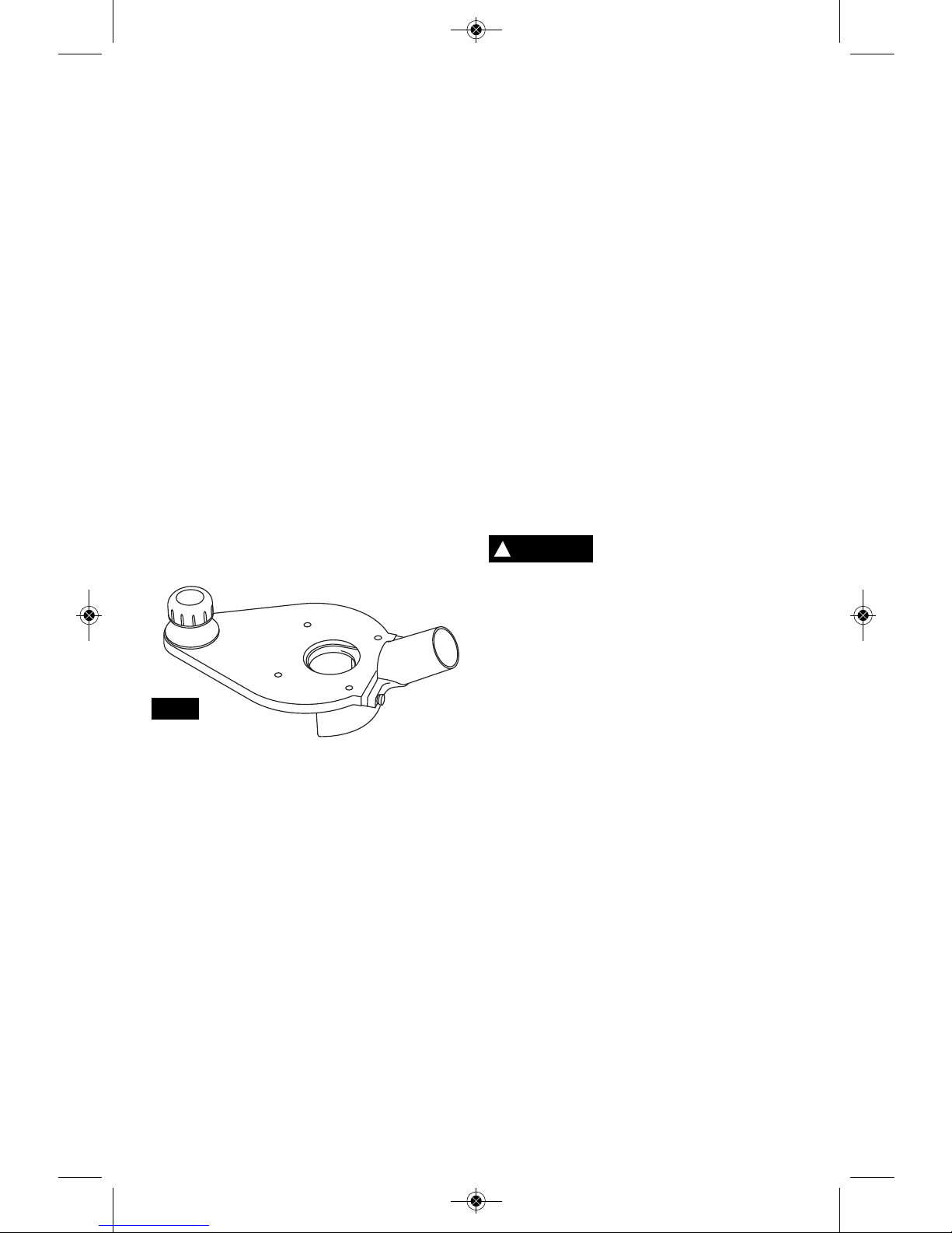
PR007 SIDE-HANDLE SUBBASE
(Available as optional accessory)
See PR007 instruction sheet for complete
information about this accessory.
The PR007 Side-Handle Subbase and Dust
Extraction Kit (Fig. 36) is a versatile accessory
that provides several useful features:
• Additional means of supporting the router
• Dust extraction and collection capability
PR007 Attachment to PR001 Fixed base
1. Remove regular subbase
2. Attach sid e ha n dle subbase with the
panhead screws that are included with it.
Additional Means of Supporting
the Router
The knob handle on the PR007 subbase
provides an additional gripping point for the
palm router / side-handle subbase assembly. It
is designed for use when the palm routers are
being used in applications that are wide
enough that the knob sits over the workpiece.
Holding the knob and keeping it pressed down
over the workpiece helps keep the routers’
angle to the workpiece unchanged, and is
especially helpful when routing edges.
Attachment of PR006 Underscribe
Attachment
The PR006 Underscribe Attachment can also
be used with the palm router and the sidehandle subbase.
Note: When the underscribe attachment is
used with the side-handle subbase, the longer
set of attachment screws should be used.
Ple ase re f er to PR006 Undersc r ibe
Attachment section for further instructions.
Dust Extraction & Collection Capability
If you have a shop vacuum system, you can
connect it to the PR007’s dust extraction
attachment to remove routing dust and debris
for enhanced utility, visibility and accuracy.
The dust collection capability of the PR007 can
be used in both common types of router
applications:
1. Routing on flat surfaces
2. Edge-forming
To reduce the risk of injury,
do not reach in area of the
bit while the router is ON or plugged in. To
avoid entangling hoses, do not use this
dust extraction hood at the same time as
any other dust extraction hood.
Dust Extraction when Routing on
Flat Surfaces
Attach the dust port on the back end of the
subbase.
1. Position the port on the backside of subbase
2. Affix using two thumbscrews included.
Dust Extraction when Edge-forming
Attach the dust hood and port on the back end
of the subbase.
1. Positi o n the hood on the backsid e of
subbase
2. Position the port on the backside of the dust
hood.
3. Affix using two thumbscrews included.
Vacuum Hose Compatibility
The dust port is sized to accept 35mm vacuum
hoses. The PR007 includes the VAC002
adapter that will allow the port to be connected
to 1-1/4” and 1-1/2” vacuum hoses. An adapter
to connect the hood to 2-1/2" hoses is also
available separately.
FIG. 36
!
WARNING
BM 2610021461 06-12_BM 2610021461 06-12.qxp 6/26/12 1:38 PM Page 21
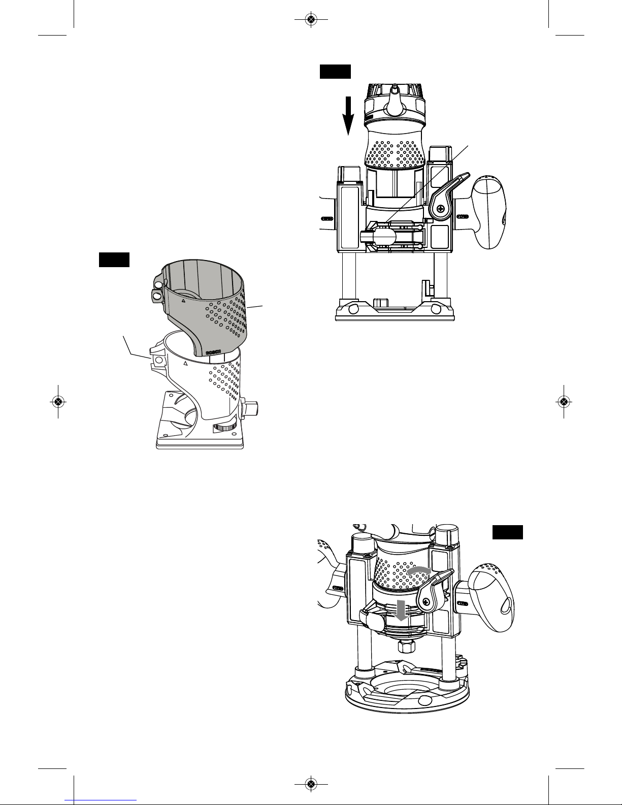
PR008 BASE COVER
(Included with PR004 Offset Base. Also
available as optional accessory)
The optional PR008 Base Cover (Fig. 37) is
available to provide insulation from tool heat
in continuous and/or high-usage applications.
It can be used on the PR001 Fixed Base,
PR005 Tilt Base, and PR004 Offset Base
(with which it is standard equipment).
Installation of Base Cover
1. Remove clamp.
2. Slide cover over the top of the base and
into position
3. Reattach clamp. Make sure that washers
sit on outside of cover.
PR011 PLUNGE BASE
To install motor in plunge base:
1. Release the base clamp lever.
2. Line up the double triangle on the base with
double triangle on the motor. (Fig. 38)
•To position switch on the right side of the
base, line up the base’s arrow with arrow
on the motor housing that is below the
cord.
• To position switch on the left, line up the
base’s arrow with arrow on the motor
housing that is below the switch.
3. Slide motor into base until resistance in felt.
(The base’s guide pin is now engaged into
slot on motor.)
4. Turn the motor clockwise until it stops.
5. Push the motor into the base as far as it will
go.
6. Fasten the base clamp lever.
DEPTH ADJUSTMENT
Th e plunge fe a ture simplif ies depth
adjustments and will allow the cutting bit to
easily and accurately enter the workpiece.
1. To lower, push plunge lock lever to the left,
apply downward pressure until you reach
desired depth, and release pressure on
lever to lock (Fig. 39). The plunge lock lever
is spring loaded and returns automatically to
the locked position.
2. To raise the router, push plunge lock lever to
the left, release pressure on router and the
router will automatically retract the bit from
the workpiece. It is advisable to retract the
bit whenever it is not engaged in work piece.
-22-
FIG. 37
BASE
COVER
REMOVE
CLAMP
BASE
CLAMP
LEVER
FIG. 38
FIG. 39
BM 2610021461 06-12_BM 2610021461 06-12.qxp 6/26/12 1:38 PM Page 22
-23-
DEPTH ROD AND TURRET
The depth rod and the depth stop turret are
used to control cutting depth as follows;
1. With the bit installed, gently lower the motor
until the tip of the router bit just contacts the
level surface the router is sitting on. This is
the “zero” position, from which further depth
adjustments can be accurately made.
2. Rotate depth stop turret until the lowest step
is aligned with the depth rod. Loosen depth
indicator knob and lower the depth rod until
it contacts the lowest step of the turret. Slide
the depth indicator until the red line indicates
zero on the depth scale, indicating the point
at which the bit just contacts the work
(Fig. 40).
3. Slide the depth rod up until the red depth
indicator line attains the desired cutting
depth, and secure the rod in position by
firmly tightening the depth indicator knob.
4. The desired depth of cut may now be
achieved by plunging the router until the
depth rod contacts the lowest stop on the
turret.
ALTERNATE SET-UP FOR
DEPTH ROD AND TURRET
1. An alternative to place a jig of the desired
routing depth (such as a hinge which needs
to be mortised) on the bottom step of the
turret.
2. Next, lower the depth rod until it contacts
the jig.
3. Secure the rod in position by firmly
tightening the depth indicator knob.
4. Finally, remove the jig.
DEEP CUTS
For deeper cuts, make several progressively
deeper cuts by starting with the highest step on
the depth turret, and after each cut, rotate the
depth turret to progressively lower steps as
desired, until the final depth (lowest step or flat)
is reached. Steps progress by 1/8” increments.
To be certain that your depth settings are as
desired, you may want to make test cuts in
scrap material before beginning work.
FINE ADJUSTMENT
The PR011 plunge base is equipped with a
fine adjustment system that allows you to
micro adjust the plunge depth of the router bit
for superior routing accuracy.
Eac h complete revolution of the fine
adjustment knob adjusts the plunging depth by
1/32”, and each of the four indicator marks on
the knob represents 1/128”.
To use the fine adjustment knob, once the
depth rod and turret have been set, check the
final depth setting and fine-adjust as follows:
To micro-increase the plunge depth, raise the
fine adjustment stop by turning it counterclockwise by the desired amount.
To micro-reduce the plunge depth, lower the
fine adjustment stop by turning it clockwise by
the desired amount.
Notes:
• When micro-adjusting the plunge depth, it is
mo r e conveni e nt to move the fine
adjustment stop up than down. Before
setting the depth rod and turret, make sure
the fine adjustment stop has been turned
sev eral revoluti o ns down from its top
position so that it can be adjusted upward.
• The fine adjustment stop cannot be used to
reduce the plunge depth when the depth rod
is already touching the depth stop turret.
The router must be raised before such an
adjustment can be made.
THE PR012 ROUTER DUST COLLECTION
FOR PLUNGE BASE
This dust extraction hood is designed for use
the plunge base (PR011) when routing is done
in the middle of the workpiece, such as when
creating slots or routing patterns for inlays. If
you have a shop vacuum system, you can
attach the dust extraction hood for improved
visibility, accuracy and utility, particularly in
freehand routing.
To attach, position as shown and secure
ada pter to base wit h the thumbscrews
provided (Fig. 41).
The dust extraction hood can also be installed
with the hose outlet facing the front of the tool.
2
1
0
IN
50
40
30
20
10
0
MM
DEPTH
INDICATOR
DEPTH
INDICATOR
KNOB
DEPTH STOP
TURRET
DEPTH ROD FINE
ADJUSMENT
KNOB
FIG. 39
FIG. 40
BM 2610021461 06-12_BM 2610021461 06-12.qxp 6/26/12 1:38 PM Page 23
-24-
EDGEFORMING DUST
EXTRACTION HOOD RA1175
Do not reach in area of the
bit while the router is ON or
plugged in. To avoid entangling hoses, do
not use this dust extraction hood at the
same time as any other dust extraction
hood.
This dust extraction hood (optional accessory)
is used for dust collection when edge-forming
(Fig. 42).
ATTACHING DUST EXTRACTION
HOOD
You can attach the edge-forming hood in
several places according to your needs or
preferences. The dust hood is attached to the
plunge base using two M4 thumb screws Two
auxiliary holes are provided in the plunge base
for attachment. Attach the dust extraction hood
— over the router’s sub-base — using the
screws provided with the hood. Securely
tighten the screws. (Figures 42 & 43).
DELUXE ROUTER GUIDE
(Not included, available as accessory)
The Bosch deluxe router guide is an optional
accessory that will guide the router parallel to a
straight edge or allow you to create circles and
arcs.
The deluxe router guide is supplied with two
rods and screws to fasten the guide (Fig. 44).
In addition, it features a fine adjustment knob
and indicator for accurately positioning the
edge guide relative to the bit. With the guide
installed and adjusted, the router should be fed
normally, keeping the guide in contact with the
edge of the workpiece at all times. The deluxe
router guide may also be positioned directly
under the router base for operations where a
cut is needed close to or at the edge of the work.
The deluxe router guide includes a dus t
extraction hood and the VAC002 vacuum hose
adapter.
For complete instructions on installation and
operation, please refer to the instructions
which are included with this accessory.
!
WARNING
DUST EXTRACTION
HOOD
WORKPIECE
EDGE
ROUTER
SUBBASE
Dust Extraction Hood
(Optional Accessory)
M4 Thumb
Screws
FIG. 41
FIG. 42
M4 x 16mm
SCREW
SUBBASE
M4 x 16mm
SCREW
FIG. 43
PLUNGE BASE
DUST EXTRACTION
HOOD
BM 2610021461 06-12_BM 2610021461 06-12.qxp 6/26/12 1:38 PM Page 24
-25-
TEMPLET GUIDES
This plunge base can also be used with the
optional Bosch-exclusive quick-change templet
guide system, which firmly grips the guides
with a spring-loaded ring. Unlike conventional
threaded templet guides, there is no threaded
ring that can come loose while routing. (Fig. 45)
INSTALLING TEMPLET GUIDE ADAPTER
(Not included, available as accessory)
Place templet guide adapter over the holes in
the center of the sub-base, and align the two
threaded holes in the bottom of adapter with
the countersunk holes in subbase. Fasten
adapter with the screws provided. Note that
the adapter is reversible, so the release lever
may be positioned as desired. (Fig. 46)
CENTERING THE SUB-BASE OR
TEMPLET GUIDES
Your PR011 plunge base features the Bosch
“Precision Centering Design”. Its subbase is
precisely centered at the factory. This positions
the bit at the center of the subbase and
optional templet guides.
Precision centering allows you to use the edge
of the subbase or templet guides to closely
follow jigs such as straight guides, templets,
and dovetail fixtures without worrying about bit
walk-off from the intended cut line for any
reason, including the orientation of the router’s
handles relative to the jig.
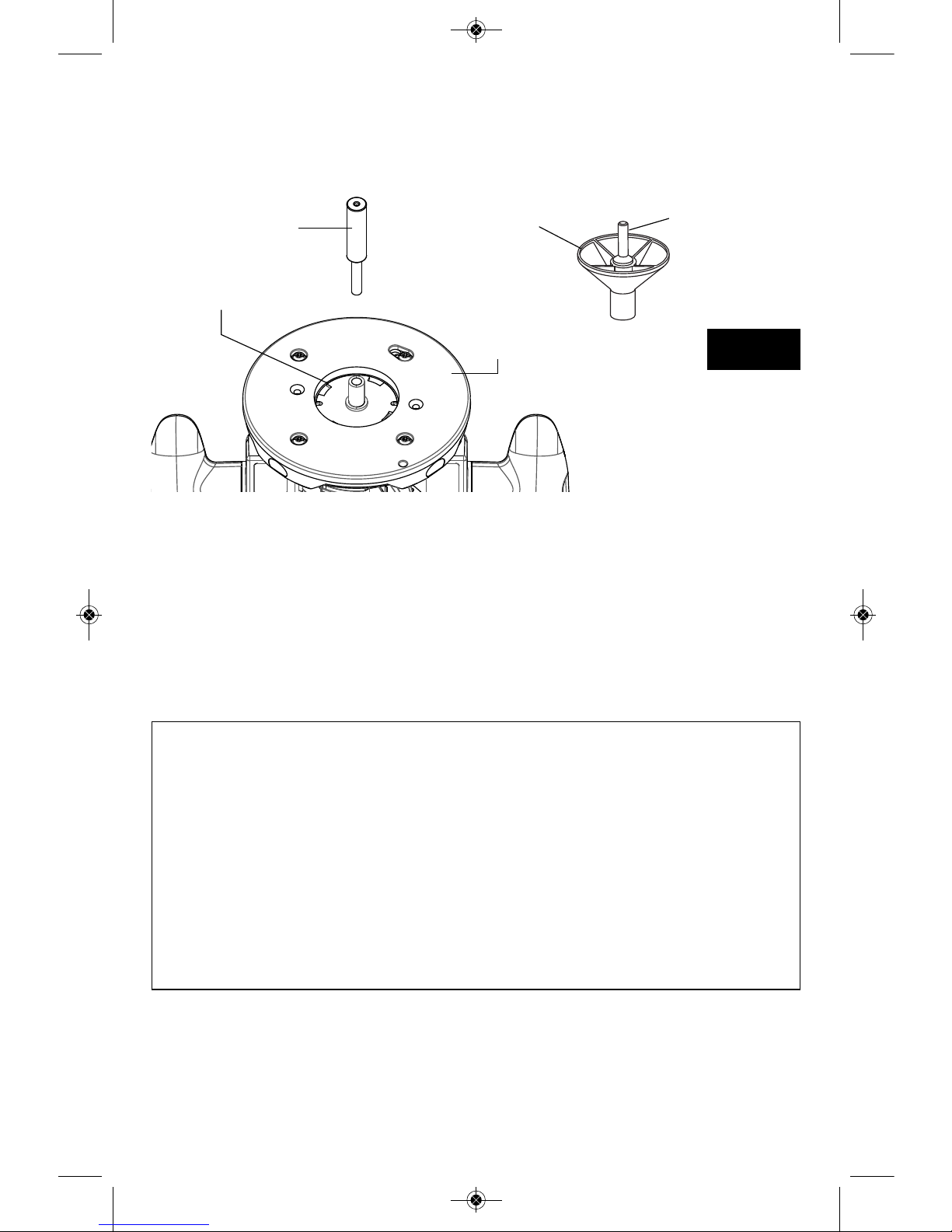
To most precisely re-center the subbase or
templet guides, attach the subbase using the
optional Bosch RA1151 Centering Device.
Follow steps 1-8 (Fig. 47).
1. If a templet guide is to be centered, Install
the templet guide adapter and template
guide (optional attachments) as described
elsewhere in this manual.
2. Loosen the four screw s that hold the
subbase to the base.
3. Prepare the Centering Device:
• Use narrow end of steel shaft.
• When centering subbase or templet guide
that has opening of more than ½”, slide
the wide plastic sleeve over the steel
shaft.
4. Slide centering sleeve through the subbase
or templet guide and into collet. Tighten
collet nut with fingers to put slight grip on
centering cone.
BASE
CUT
DESIRED
WIDTH
M6 WING SCREW
ROUTER
GUIDE RODS
FINE ADJUSTMENT
KNOB
FINE
ADJUSTMENT
INDICATOR
WORKPIECE
FEED
DIRECTION
FIG. 44
TEMPLET GUIDE
ADAPTER
(optional accessory)
MOUNTING SCREWS
FIG. 46
TEMPLET GUIDE
ADAPTER
TEMPLET GUIDE
RELEASE LEVER
TEMPLET GUIDE
(optional accessory)
FIG. 45
BM 2610021461 06-12_BM 2610021461 06-12.qxp 6/26/12 1:38 PM Page 25
-26-
5. Lightly press centering sleeve into sub-base
or templet guide to center.
6. Tighten the pan-head screws. Remove
centering sleeve.
7. The precision centering of the subbase or
templet guide is complete.
CENTERING CONE – Used when centering
the subbase itself or wide templet guides.
CENTERING SHAFT
(optional accessory)
TEMPLET GUIDE
(optional accessory)
SUBBASE
CENTERING CONE
(optional accessory)
FIG. 47
PLUNGE BASE
CENTERING SHAFT
(optional accessory)
Bosch Bushing External Internal Max
Templet Depth Diameter Diameter Bit/Cutter
Guide Diameter
ABB
RA1101 3/16” 5/16” 1/4” 3/16”
RA1103 9/64” 5/16” 17/64” 13/64”
RA1105 9/64” 7/16” 3/8” 5/16”
RA1107 5/16” 7/16” 3/8” 5/16”
RA1109 7/16” 1/2” 13/32” 11/32”
RA1111 3/16” 5/8” 17/32” 15/32”
RA1113 1/2” 5/8” 17/32” 15/32”
RA1115 3/16” 3/4” 21/32” 19/32”
RA1117 31/64” 13/16” 5/8” 9/16”
RA1119 31/64” 1” 25/32” 21/32”
RA1121 7/16” 1-3/8” 1-19/64” 1-15/64”
MAXIMUM BIT/CUTTER SIZE FOR
TEMPLET GUIDES
When using a templet guide, use only router
bit with cutters that are 1/16” less than the
internal diameter of the templet guide, such as
in the table below.
USE WITH THREADED
TEMPLET GUIDES
Also available as an optional accessory is an
additional adapter, the RA1100, that allows
use of conventional threaded templet guides
with the Bosch quick-release system.
BM 2610021461 06-12_BM 2610021461 06-12.qxp 6/26/12 1:38 PM Page 26
 Loading...