

Page 1
Service guide
230 V 1 N~/400 V 3 N~
Split Outdoor unit
6 720 813 707-00.2I
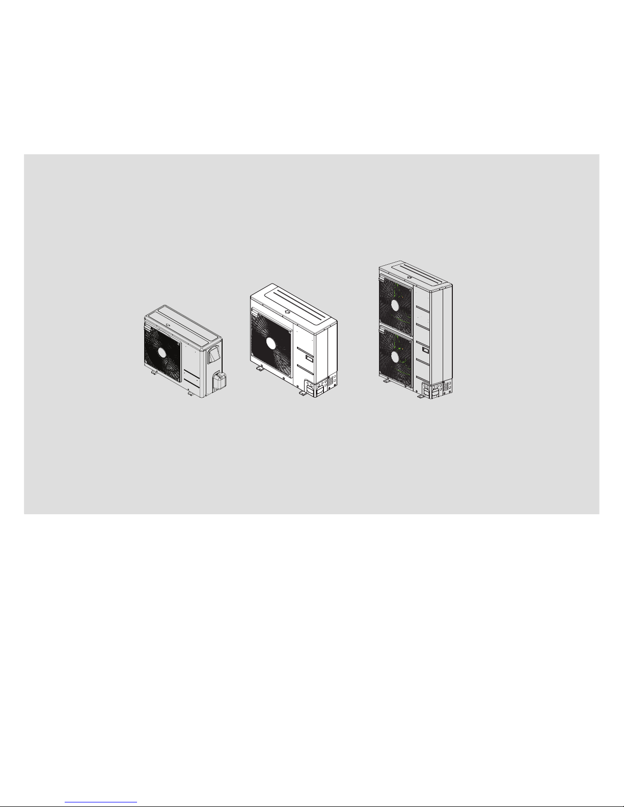
ODU Split 2
ODU Split 4...8
ODU Split 11t...15t
ODU Split 11s...15s
6 720 817 722 (2015/06)
Page 2
Table of contents
Split ODU – 6 720 817 722 (2015/06)
2
Table of contents
1 Key to symbols and safety instructions . . . . . . . . . . . . . . . . . . . 2
1.1 Key to symbols . . . . . . . . . . . . . . . . . . . . . . . . . . . . . . . . . . 2
1.2 General safety instructions . . . . . . . . . . . . . . . . . . . . . . . . 2
2 Error handling instructions for Split outdoor unit . . . . . . . . . . 3
2.1 Names of units . . . . . . . . . . . . . . . . . . . . . . . . . . . . . . . . . . 3
2.2 List of error codes . . . . . . . . . . . . . . . . . . . . . . . . . . . . . . . 3
2.3 Error code 21 . . . . . . . . . . . . . . . . . . . . . . . . . . . . . . . . . . 4
2.3.1 Error diagnosis and countermeasure flow chart . . . . . . . 5
2.4 Error code 22 . . . . . . . . . . . . . . . . . . . . . . . . . . . . . . . . . . 8
2.4.1 Error diagnosis and countermeasure flow chart . . . . . . . 8
2.5 Error code 23 . . . . . . . . . . . . . . . . . . . . . . . . . . . . . . . . 11
2.5.1 Error diagnosis and countermeasure flow chart . . . . . 11
2.6 Error code 26 . . . . . . . . . . . . . . . . . . . . . . . . . . . . . . . . 14
2.6.1 Error diagnosis and countermeasure flow chart . . . . . 14
2.7 Error code 27 . . . . . . . . . . . . . . . . . . . . . . . . . . . . . . . . 17
2.7.1 Error diagnosis and countermeasure flow chart . . . . . 17
2.8 Error code 29 . . . . . . . . . . . . . . . . . . . . . . . . . . . . . . . . 20
2.8.1 Error diagnosis and countermeasure flow chart . . . . . 20
2.9 Error code 32 . . . . . . . . . . . . . . . . . . . . . . . . . . . . . . . . 21
2.9.1 Error diagnosis and countermeasure flow chart . . . . . 21
2.10 Error code 35 . . . . . . . . . . . . . . . . . . . . . . . . . . . . . . . . 22
2.10.1 Error diagnosis and countermeasure flow chart . . . . . 22
2.11 Error code 41, 44, 45, 46, 48 . . . . . . . . . . . . . . . . . . . 23
2.11.1 Error diagnosis and countermeasure flow chart . . . . . 23
2.12 Error code 43 . . . . . . . . . . . . . . . . . . . . . . . . . . . . . . . . 24
2.12.1 Error diagnosis and countermeasure flow chart . . . . . 24
2.13 Error codes 52, 53 . . . . . . . . . . . . . . . . . . . . . . . . . . . . 25
2.13.1 Error code 52 . . . . . . . . . . . . . . . . . . . . . . . . . . . . . . . . 25
2.13.2 Error code 53 . . . . . . . . . . . . . . . . . . . . . . . . . . . . . . . . 27
2.14 Error code 54 . . . . . . . . . . . . . . . . . . . . . . . . . . . . . . . . 27
2.15 Error code 60 . . . . . . . . . . . . . . . . . . . . . . . . . . . . . . . . 27
2.16 Error code 61 . . . . . . . . . . . . . . . . . . . . . . . . . . . . . . . . 29
2.16.1 Error diagnosis and countermeasure flow chart . . . . . 29
2.17 Error code 62, 65 . . . . . . . . . . . . . . . . . . . . . . . . . . . . . 30
2.17.1 Error diagnosis and countermeasure flow chart . . . . . 30
2.18 Error code 67 . . . . . . . . . . . . . . . . . . . . . . . . . . . . . . . . 32
2.18.1 Error diagnosis and countermeasure flow chart . . . . . 32
3 Check compressor resistances . . . . . . . . . . . . . . . . . . . . . . . . 34
4 Compressor replacement . . . . . . . . . . . . . . . . . . . . . . . . . . . . . 35
5 Check system parameters . . . . . . . . . . . . . . . . . . . . . . . . . . . . 36
6 Electronic expansion valve . . . . . . . . . . . . . . . . . . . . . . . . . . . 36
7 Fan motor . . . . . . . . . . . . . . . . . . . . . . . . . . . . . . . . . . . . . . . . . . 38
8 Replacement procedure for INV PCB . . . . . . . . . . . . . . . . . . . 39
9 Other pre - checkings . . . . . . . . . . . . . . . . . . . . . . . . . . . . . . . . 41
1 Key to symbols and safety instructions
1.1 Key to symbols
Warnings
The following keywords are defined and can be used in this document:
• NOTICE indicates a situation that could result in damage to property
or equipment.
• CAUTION indicates a situation that could result in minor to medium
injury.
• WARNING indicates a situation that could result in severe injury or
death.
• DANGER indicates a situation that will result in severe injury or
death.
Important information
Additional symbols
1.2 General safety instructions
These installation instructions are intended for plumbers, heating
engineers and electricians.
▶ Read any installation instructions (outdoor unit, heating controls,
etc.) carefully before starting the installation.
▶ Observe the safety instructions and warnings.
▶ Observe national and regional regulations, technical rules and
guidelines.
▶ Record all work carried out.
Intended use
This outdoor unit must only be used as a heat appliance in a sealed hot
water heating system for domestic purposes.
Any other use is considered inappropriate. Any damage that results from
such use is excluded from liability.
Installation, commissioning and servicing
Installation, commissioning and servicing must only be carried out by an
authorised contractor.
▶ Only use original spares.
Electrical work
Electrical work must only be carried out by qualified electricians.
▶ Before starting electrical work:
– Isolate all poles of the mains voltage and secure against
reconnection.
– Using suitable means, test that the power supply is disconnected.
▶ Also see connection diagrams of other system components.
Warnings in this document are identified by a warning
triangle printed against a grey background.
Keywords at the start of a warning indicate the type and
seriousness of the ensuing risk if measures to prevent
the risk are not taken.
This symbol indicates important information where
there is no risk to people or property.
Symbol Explanation
▶ Step in an action sequence
Cross-reference to another part of the document
• List entry
– List entry (second level)
Table 1
Page 3
Error handling instructions for Split outdoor unit
Split ODU – 6 720 817 722 (2015/06)
3
Handling refrigerant
The air to water outdoor unit is filled with R410A refrigerant.
▶ Only qualified and authorised refrigeration engineers may work on
the refrigerant circuit.
▶ For all work with refrigerant, wear suitable safety gloves and goggles.
What to do if refrigerant leaks
If refrigerant leaks and touches the skin, it can cause frostbite.
▶ In case of a refrigerant leak, never touch any part of the air to water
outdoor unit.
▶ Avoid skin or eye contact with refrigerant.
▶ Seek medical attention if you get refrigerant on your skin or in your
eyes.
▶ If the refrigerant leaks please contact your installer immediately.
Handover to the user
When handing over the heating system, instruct the user in its operation
and operating conditions.
▶ Explain the operation - with particular emphasis on all safety-related
actions.
▶ Explain that conversions and repairs must only be carried out by an
approved contractor.
▶ Point out the need for inspections and maintenance for safe and
environmentally-compatible operation.
▶ The installation and operating instructions must be given to the user
for keeping.
2 Error handling instructions for Split outdoor unit
2.1 Names of units
2.2 List of error codes
Supplier name for ODU BTT name for ODU
AHUW036A2 ODU Split 2
AHUW056A2 ODU Split 4
AHUW076A2 ODU Split 6
AHUW096A2 ODU Split 8
AHUW126A2 ODU Split 11s
AHUW146A2 ODU Split 13s
AHUW156A2/166A2 ODU Split 15s
AHUW128A2 ODU Split 11t
AHUW148A2 ODU Split 13t
AHUW158A2/168A2 ODU Split 15t
Table 2 Names of units
HMI Error code ODU Error code Description Error characteristc Remark
5600, 5601 21 DC Peak (IPM Fault)
IPM = Intelligent Power module
Restart 10x/hour,
then blocked
Compressor broken or too much refrigerant in
compressor
5602, 5603 22 CT 2 (Max CT) Restart after
problem has
vanished
Inverter current > 14 A
5604, 5605 23 DC Link Voltage is low or high Restart after
problem has
vanished
Direct voltage
1~: <140 VDC or >480 (3kW: 420) VDC
3~: <320VDC or >780VDC
5610, 5611 26 Problem in DC Compressor
positioning
Restart 10x/hour,
then blocked
Wrong orientation of compressor connections
(UVW)
5612, 5613 27 PSC Fault Restart 10x/hour,
then blocked
High current IGBT (check reactor)
5616, 5617 29 High current at Compressor
phases
Restart 10x/hour,
then blocked
5618, 5619 32 Temperature at discharge-pipe is
too high
Restart after
problem has
vanished
Hot gas temperature TH5 >105 °C (check
refrigerant load)
5666, 5667 35 Low Pressure error Restart 3x/hour,
then blocked
Low Pressure < 0 kPa
( – 49.5 °C)
5622, 5623 41 Problem in discharge-pipe
temperature sensor
Direct shut-down Sensor TH5 broken (200k >25 °C)
5662, 5663 43 High-pressure sensor (Open/
Short)
Direct shut-down LP/HP sensor broken
5624, 5625 44 Problem in ambient temperature
sensor
Direct shut-down Sensor TH7 broken (10k >25 °C)
5626, 5627 45 Problem in condenser-middle-pipe
temperature sensor
Direct shut-down Sensor TH8 broken (5k >25 °C)
5628, 5629 46 Problem in suction-pipe
temperature sensor
Direct shut-down Sensor TH4 broken (5k >25 °C)
Table 3 Error codes
Page 4
Error handling instructions for Split outdoor unit
Split ODU – 6 720 817 722 (2015/06)
4
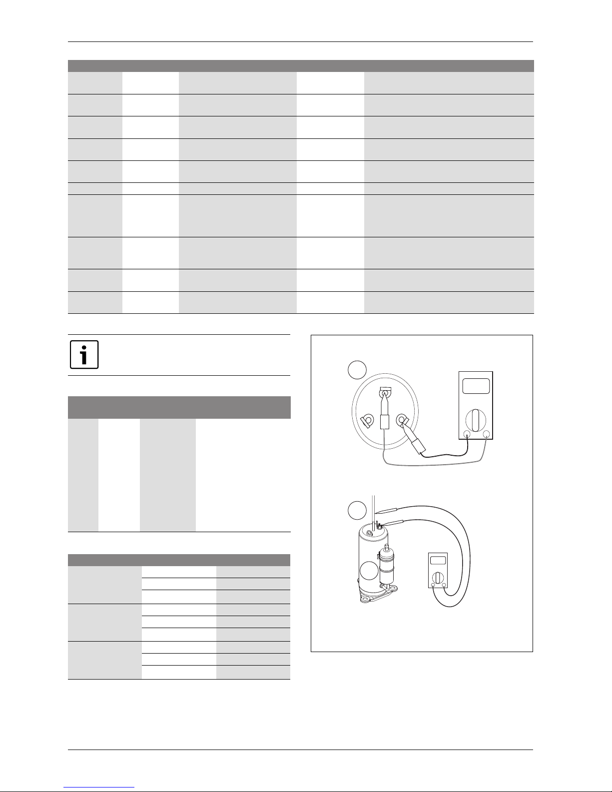
2.3 Error code 21
Fig. 1 Resistance measurement on compressor
[1] Compressor
[2] Copper pipe
5664, 5665 48 Cond. Out-pipe Th Error (Open/
Short)
Direct shut-down Sensor TH6 broken (5k >25 °C)
5632, 5633 52 Bad communication between
Inverter-PCB and Main-PCB
Restart 3x/hour,
then blocked
Wiring between Mainboard and Inverter board
damaged (3~ phase only)
5634, 5635 53 Bad communication between Can-
PCB and Main-PCB
Direct shut-down Wiring between Mainboard and CAN-PCB
damaged
5636, 5637 54 Phase sequence incorrect Restart 10x/hour,
then blocked
only 2 phases or incorrect rotation field
(3~ phase only)
5668, 5669 55 CAN Communication error (CAN-
PCB <=> Installerboard)
Direct shut-down Wiring between CAN-PCB and Indoor unit
damaged
5638, 5639 60 EEPROM Checksum mismatched Direct shut-down Change EEPROM
5640, 5641 61 Temperature at condenser-pipe is
too high
Restart after
problem has
vanished
Condensing temperature >65.3°C (4199 kPa)
{Heating}
Condensing temperature >64.2
°C(4101 kPa)
{Cooling}
5642, 5643 62 Temperature at heat sink is too
high
Restart after
problem has
vanished
Heat sink temperature >85 °C
5646, 5647 65 Problem in heatsink temperature
sensor
Direct shut-down Heat sink sensor / Inverter-PCB broken
5670, 5671 67 ODU BLDC fan lock Restart 10x/hour,
then blocked
Fan blocked
HMI Error code ODU Error code Description Error characteristc Remark
Table 3 Error codes
When the outdoor unit (ODU) is blocked the error can be
acknowledged by power ON/OFF.
Display
code
Title Cause of error
Check point & Normal
condition
21 DC PEAK
(IPM fault)
-Instant over
current
-Over rated
current
-Poor insulation
of IPM
-An instant over current in
the U,V,W phase
-Comp lock
-The abnormal connection of
U,V,W
-Over load condition
-Overcharging of refrigerant
pipe length
-Outdoor fan has stopped
-Poor insulation of
compressor
Table 4 Error code 21
ODU model Resistance () at 25 °C
ODU Split 4
ODU Split 6
ODU Split 8
U-V
0.628
V-W
0.628
W-U
0.628
ODU Split 11s
ODU Split 13s
ODU Split 15s
U-V
0.438
V-W
0.438
W-U
0.438
ODU Split 11t
ODU Split 13t
ODU Split 15t
U-V
0.845
V-W
0.845
W-U
0.845
Table 5 Resistance between phases
V
U
W
6 720 817 722-01.1I
1
2
1
Page 5
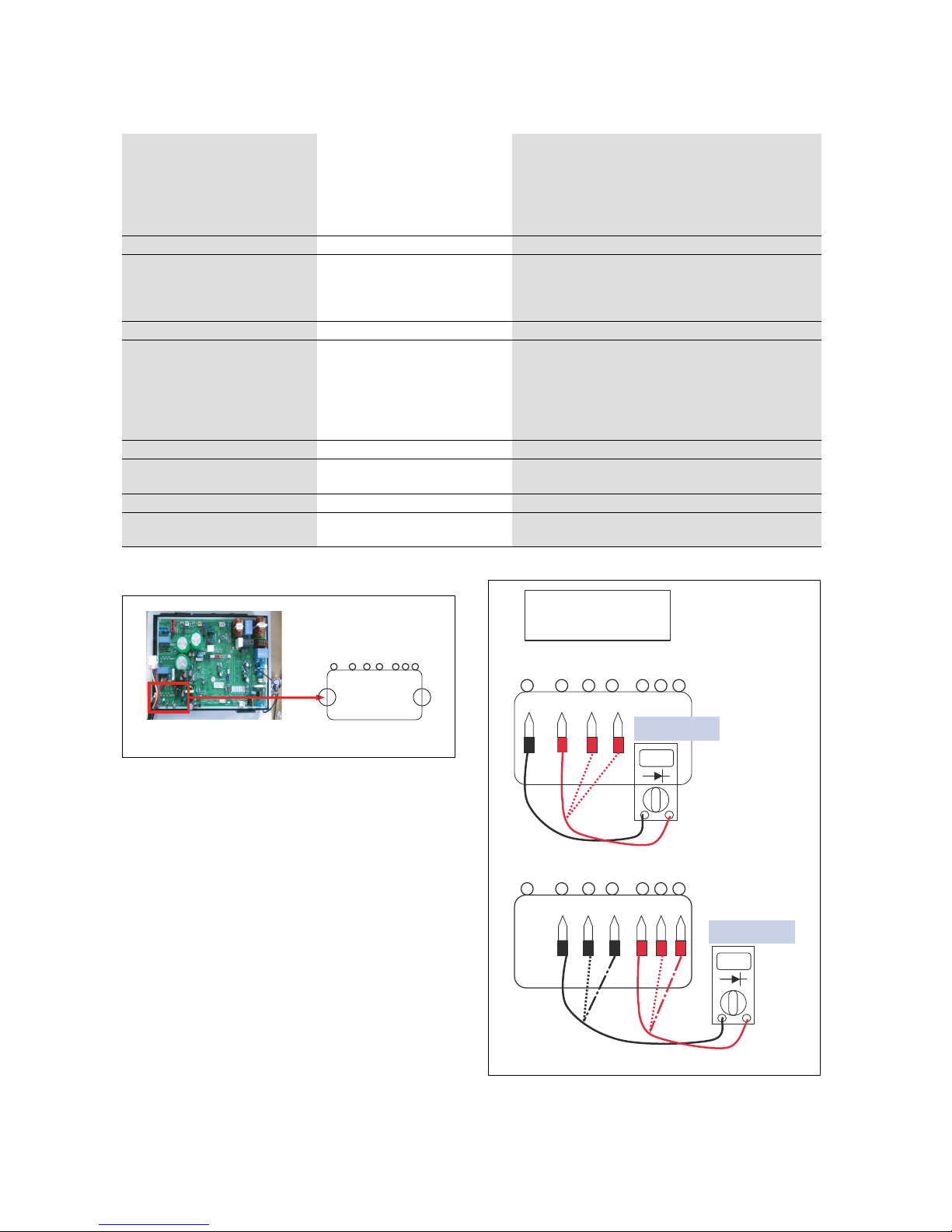
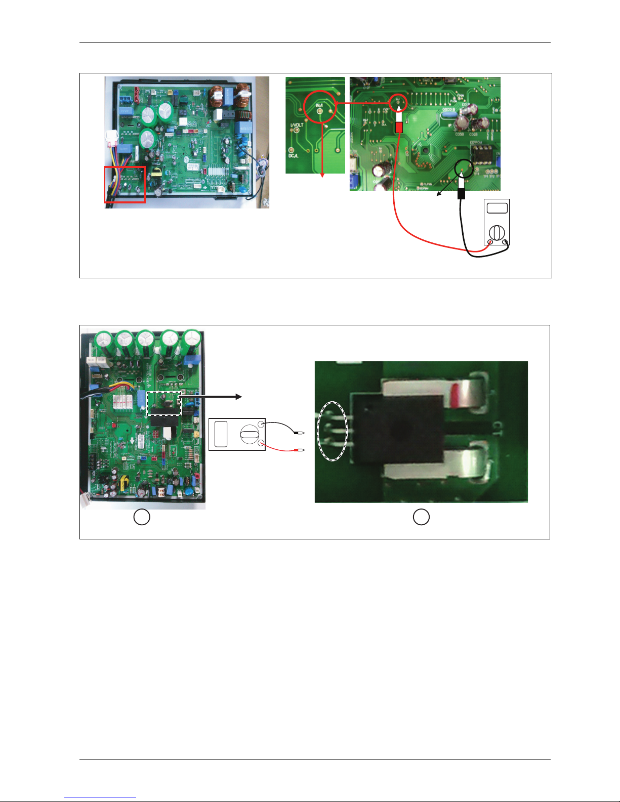
2.3.1 Error diagnosis and countermeasure flow chart
ODU Split 4, 6 and 8
Fig. 2 ODU Split 4, 6, 8
1. Wait until PCB (Inverter) DC voltage is discharged after main
power is shut off.
2. Pull out V, W, U COMP connector.
3. Set multi tester to resistance mode.
4. If the value between P and N terminal of IPM is short (0) or open
(hundreds M), PCB (Inverter) needs to be replaced, IPM is
damaged.
5. Set the multi tester to diode mode.
6. In case measured value is different from the table, PCB (Inverter)
needs to be replaced. PCB (Inverter) is damaged.
Fig. 3 PFC_IPM check
ODU Split 11s, 13s, 15s
Is installation condition normal? No -> 1. Check pipe clogging / distortion
2. Check covering (unit)
3. Check EEV connector assembly condition / normal
operation
4. Check refrigerant pressure
-> Reassemble or manage if abnormality found
Yes
Are the resistance between each phase
and insulation resistance of inverter
compressor normal?
No ->
1. Check resistance between each terminal of compressor
2. Check insulation resistance between compressor terminal
and pipe
-> Replace compressor if abnormality is found
Yes
Is compressor wire connection
condition normal?
No -> 1. Check inverter PCB assembly 1 U,V,W connector
cennection condition
2. Check wire disconnection and wiring
3. Check compressor terminal connection condition (bad
contact)
-> Reassemble if abnormality is found
Yes
Is inverter PCB assembly 1 normal? No -> 1. Check inverter PCB assembly 1 IPM normality
-> Replace inverter PCB assembly 1
Yes
Recheck power and installation
condition
Table 6 Error diagnosis and countermeasure chart
SPM3
27 26 25 24 23 22 21
P W V U Nw Nv Nu
6 720 817 722-02.1I
27 26 25 24 23 22 21
P W V U Nw Nv Nu
0.4 ~ 0.6 V
P W V U Nw Nv Nu
27 26 25 24 23 22 21
0.4 ~ 0.6 V
PFC_IPM check
U, V, W ‘ R S T
6 720 817 722-03.1I
Page 6
Error handling instructions for Split outdoor unit
Split ODU – 6 720 817 722 (2015/06)
6
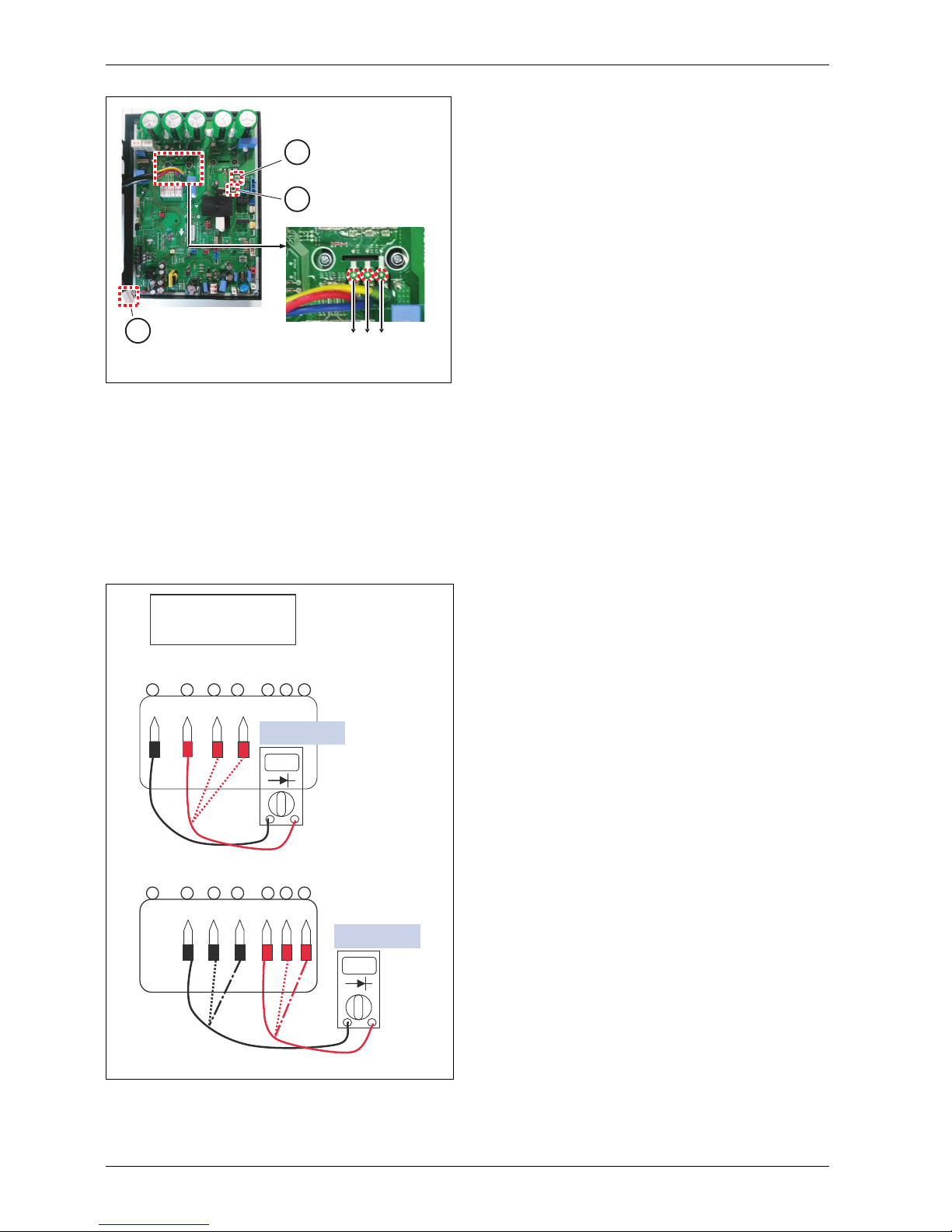
Fig. 4 ODU Split 11s, 13s, 15s
1. Wait until PCB (Inverter) DC voltage is discharged after main power
is shut off.
2. Pull out V, W, U COMP connector.
3. Set multi tester to resistance mode.
4. If the value between P and N terminal of IPM is short (0) or open
(hundreds M), PCB (Inverter) needs to be replaced, IPM is
damaged.
5. Set the multi tester to diode mode.
6. In case measured value is different from the table, PCB (Inverter)
needs to be replaced. PCB (Inverter) is damaged.
Fig. 5 PFC_IPM check
1
2
3
UVW
6 720 817 722-04.1I
27 26 25 24 23 22 21
P W V U Nw Nv Nu
0.4 ~ 0.6 V
P W V U Nw Nv Nu
27 26 25 24 23 22 21
0.4 ~ 0.6 V
PFC_IPM check
U, V, W ‘ R S T
6 720 817 722-03.1I
Page 7
Error handling instructions for Split outdoor unit
Split ODU – 6 720 817 722 (2015/06)
7
ODU Split 11t, 13t, 15t
Fig. 6 ODU Split 11t, 13t, 15t
1. Wait until PCB (Inverter) DC voltage is discharged after main power
is shut off.
2. Pull out V, W, U COMP connector.
3. Set multi tester to resistance mode.
4. If the value between P and N terminal of IPM is short (0) or open
(hundreds M), PCB (Inverter) needs to be replaced, IPM is
damaged.
5. Set the multi tester to diode mode.
6. In case measured value is different from the table, PCB (Inverter)
needs to be replaced. PCB (Inverter) is damaged.
Fig. 7 PFC_IPM check
6 720 817 722-05.1I
27 26 25 24 23 22 21
P W V U Nw Nv Nu
0.4 ~ 0.6 V
P W V U Nw Nv Nu
27 26 25 24 23 22 21
0.4 ~ 0.6 V
PFC_IPM check
U, V, W ‘ R S T
6 720 817 722-03.1I
Page 8
Error handling instructions for Split outdoor unit
Split ODU – 6 720 817 722 (2015/06)
8
2.4 Error code 22
2.4.1 Error diagnosis and countermeasure flow chart
Check Point
1. Check the power source (230V 15%).
2. Check that the fan operation is right.
3. Check the current.
4. Check the install condition.
5. Check the CT sensor output signal.
Display
code
Title Cause of error
Check point & Normal
condition
22 Max. C/T -Input Over
Current
1. Malfunction of
Compressor
2. Blocking of Pipe
3. Low Voltage Input
4. Refrigerant, Pipe length,
Blocked
Table 7 Error code 22
Is installation condition normal? No -> 1. Check pipe clogging / distortion
2. Check covering (unit)
3. Check EEV connector assembly condition / normal
operation
4. Check refrigerant pressure
-> Reassemble or manage if abnormality found
Yes
Are the resistance between each phase
and insulation resistance of inverter
compressor normal?
No -> 1. Check resistance between each terminal of compressor
2. Check insulation resistance between compressor terminal
and pipe
-> Replace compressor if abnormality is found
Yes
Is compressor wire connection
condition normal?
No -> 1. Check connection between PCB assembly and bridge diode
(misconnection, disconnection)
2. Check wire disconnection and wiring
3. Check compressor terminal connection condition (bad
contact)
-> Reassemble if abnormality is found
Yes
Is inverter PCB assembly 1 power
connection normal?
No -> 1. Check connection between PCB assembly 1 and bridge
diode (misconnection, disconnection)
-> Wiring again if abnormality is found
Yes
Is input voltage normal? No -> 1. Check L~N phase is 230V 15%
-> Check connection condition and wiring if power is
abnormal
Yes
Is PCB assembly 1 normal? No -> 1. Check PCB assembly 1 IPM normality
-> Replace inverter PCB assembly
Yes
Recheck power and installation
condition
Table 8 Error diagnosis and countermeasure chart
Page 9
Error handling instructions for Split outdoor unit
Split ODU – 6 720 817 722 (2015/06)
9
ODU Split 4, 6, 8
Fig. 8 ODU Split 4, 6, 8
▶ Check output of the CT sensor: DC 2.5 0.2V
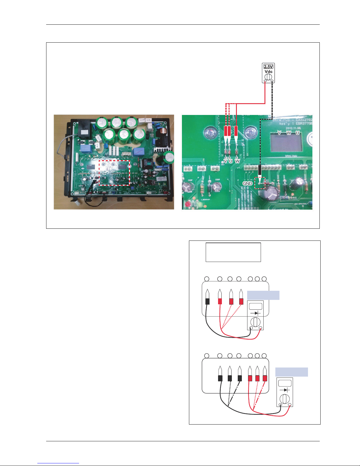
ODU Split 11s, 13s, 15s
Fig. 9 ODU Split 11s, 13s, 15s
[1] Inverter PCB
[2] CT sensing check point
▶ Check output pin 2.3 of the CT sensor: DC 2.5 0.2V
IN/I
GND
Black
Red
Vdc
6 720 817 722-06.1I
1
2
3
Vdc
6 720 817 722-07.1I
1 2
Page 10
Error handling instructions for Split outdoor unit
Split ODU – 6 720 817 722 (2015/06)
10
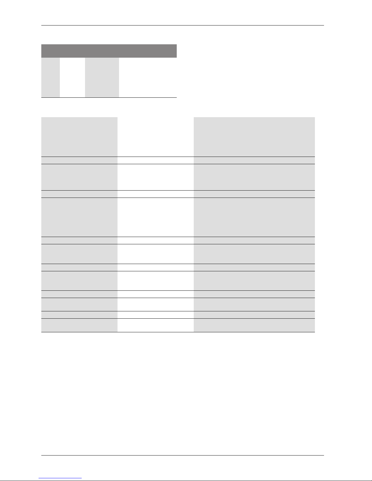
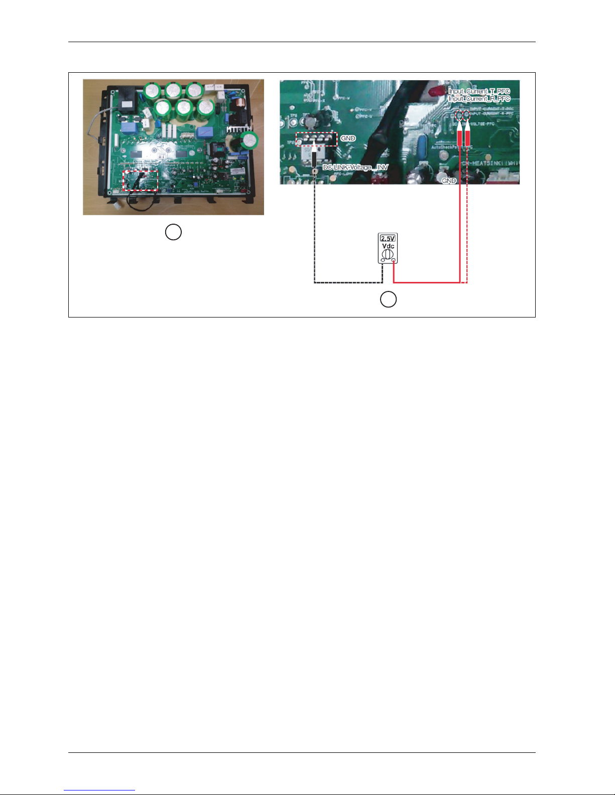
ODU Split 11t, 13t, 15t
Fig. 10 ODU Split 11t, 13t, 15t
[1] Inverter PCB
[2] CT sensing check point
▶ Check input current T_PFC and R_PFC
▶ Check output of the CT sensor: DC 2.5 0.2V
6 720 817 722-08.1I
1
2
Page 11
Error handling instructions for Split outdoor unit
Split ODU – 6 720 817 722 (2015/06)
11
2.5 Error code 23
2.5.1 Error diagnosis and countermeasure flow chart
Check Point
1. Check the WCN_P(L), P(N) connection condition ate the main PCB
(heater). Refer to wiring diagram.
2. Check the DC link voltage at no operation of compressor (280V).
3. Check the DC link voltage at operation of compressor (340V).
4. Check the DC link sensing signal (AHBW**6AO): 2.4~2.8V
(Graphic 12).
5. Check the DC link sensing signal (AHBW**8AO): 0.4~0.6V
(Graphic 13).
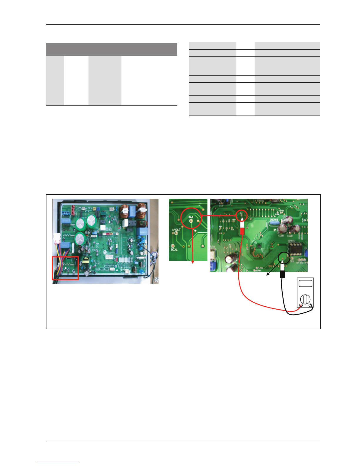
ODU Split 4, 6, 8
Fig. 11 ODU Split 4, 6, 8
Display
code
Title Cause of error
Check point & Normal
condition
23 DC link High
/ Low
voltage
• DC link
voltage is
above
420Vdc
• DC link
voltage is
below
140Vdc
1. Check CN_(L), CN_(N)
connection
2. Check input voltage
3. Check PCB DC link
voltage sensor parts
Table 9 Error code 23
Is input voltage normal? No -> 1. Check power input voltage
Yes
Is inverter PCB
assembly 1 power
connection normal?
No ->
1. Check power connection state
Yes
Is PCB (Inverter)
normal?
No -> 1. Replace PCB assembly 1
Yes
Recheck power and
installation condition
Table 10 Error diagnosis and countermeasure chart
IN/I
GND
Vdc
6 720 817 722-09.1I
Page 12
Error handling instructions for Split outdoor unit
Split ODU – 6 720 817 722 (2015/06)
12
ODU Split 11s, 13s, 15s
Fig. 12 ODU Split 11s, 13s, 15s
Vdc
P
GND
6 720 817 722-10.1I
Page 13
Error handling instructions for Split outdoor unit
Split ODU – 6 720 817 722 (2015/06)
13
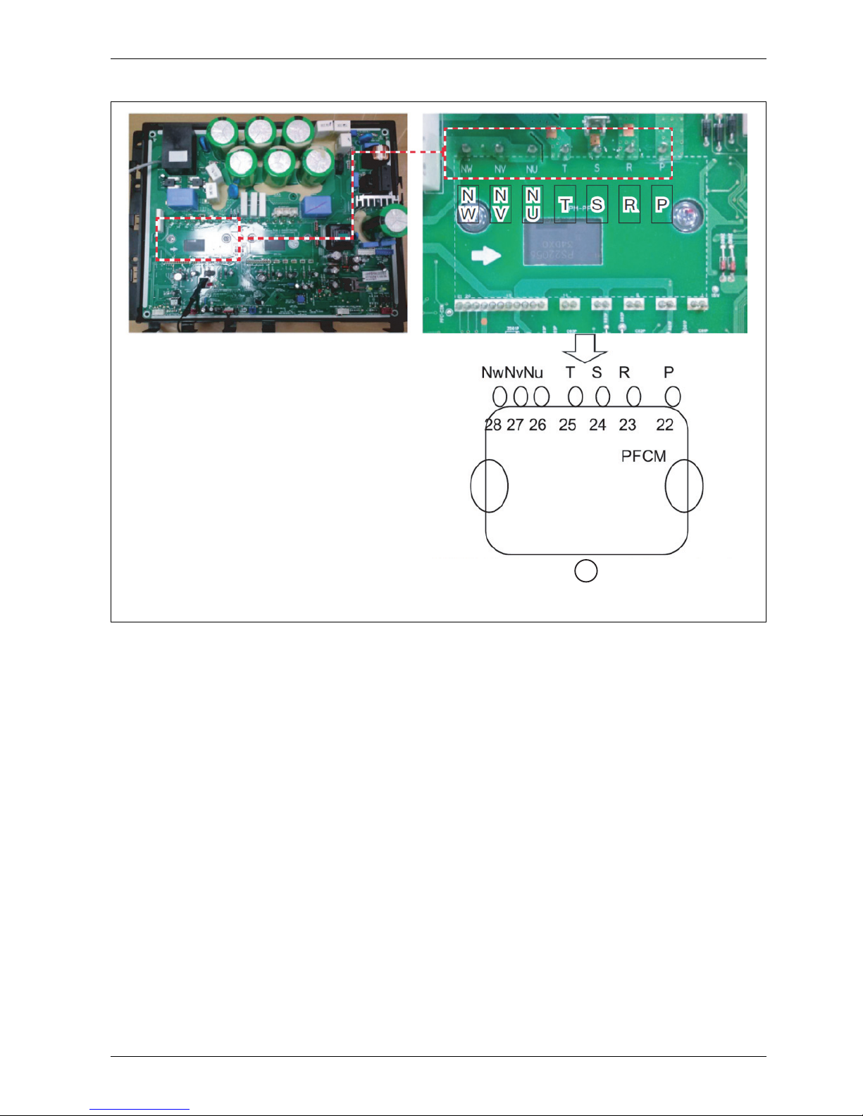
ODU Split 11t, 13t, 15t
Fig. 13 ODU Split 11t, 13t, 15t
[1] PFCM pin arrangement and pin numbers
6 720 817 722-11.1I
1
Page 14

Error handling instructions for Split outdoor unit
Split ODU – 6 720 817 722 (2015/06)
14
2.6 Error code 26
2.6.1 Error diagnosis and countermeasure flow chart
Display
code
Title Cause of error
Check point & Normal
condition
26 DC
compressor
position
• Compressor
starting
failure
1. Check the connection of
comp wire “U,V,W”
2. Malfunction of
compressor
3. Check the component of
“IPM”, detection parts
Table 11 Error code 26
Is installation condition
normal?
No -> 1. Check pipe clogging /
distortion
2. Check covering (Indoor /
Outdoor unit)
3. Check EEV connector
assembly condition / normal
operation
4. Check refrigerant pressure
-->Reassemble or manage if
abnormality found
Yes
Are the resistance
between each phase
and insulation
resistance of inverter
compressor normal?
No ->
1. Check resistance between
each terminal of compressor
2. Check insulation resistance
between compressor terminal
and pipe
--> Replace compressor if
abnormality is found
Yes
Is compressor wire
connection condition
normal?
No -> 1. Check inverter PCB assembly
U,V,W connector connection
condition
2. Check wire disconnection and
wiring
3. Check compressor terminal
condition condition (bad
contact)
--> Reassemble if abnormality is
found
Yes
Is inverter PCB
assembly normal?
No -> 1. Check inverter PCB assembly
IPM normality
--> Replace inverter PCB assembly
Yes
Recheck power and
installation condition
Table 12 Error diagnosis and countermeasure chart
Page 15

Error handling instructions for Split outdoor unit
Split ODU – 6 720 817 722 (2015/06)
15
ODU Split 4, 6, 8
Fig. 14 ODU Split 4, 6, 8
[1] CT sensing check point
[2] WVC connector check
ODU Split 11s, 13s, 15s
Fig. 15 ODU Split 11s, 13s, 15s
U, V, W
GND
Vdc
U V W
6 720 817 722-12.1I
1
2
U
W
V
GND
6 720 817 722-13.1I
Page 16

Error handling instructions for Split outdoor unit
Split ODU – 6 720 817 722 (2015/06)
16
ODU Split 11t, 13t, 15t
Fig. 16 ODU Split 11t, 13t, 15t
6 720 817 722-14.1I
Page 17

Error handling instructions for Split outdoor unit
Split ODU – 6 720 817 722 (2015/06)
17
2.7 Error code 27
2.7.1 Error diagnosis and countermeasure flow chart
PFCM module checking method
1. Set the multi tester to diode mode
2. Check short circuit between input signal pins which are placed below
PFC module
3. Replace PCB assembly 1 if it is short circuit between pins except
number 4, 5 pins.
Display
code
Title Cause of error
Check point & Normal
condition
27 DC
compressor
position
• Compressor
starting
failure
1. Check the connection of
comp wire “U,V,W”
2. Malfunction of
compressor
3. Check the component of
“IPM”, detection parts
Table 13 Error code 27
Is installation condition
normal?
No -> 1. Check pipe clogging /
distortion
2. Check covering (Indoor /
Outdoor unit)
3. Check EEV connector
assembly condition / normal
operation
4. Check refrigerant pressure
-->Reassemble or manage if
abnormality found
Yes
Is input voltage normal? No -> 1. Check that L-N phase voltage is
230 15% (1~)
2. Check that R-S-T-N phase
voltage is 380 15% (3~)
--> Check connection condition
and wiring if power is abnormal
Yes
Is AC input wire
connection condition
normal?
No -> 1. Check L-N connection
condition
2. Check wire disconnection and
wiring
--> Reassemble if abnormality
found
Yes
Is compressor wire
connection condition
normal?
No -> 1. Check PCB assembly U,V,W
connector connection
condition
2. Check wire disconnection and
wiring
3. Check compressor terminal
connection condition (bad
contact)
--> Reassemble if abnormality is
found
Yes
Is PCB assembly 1
normal?
No -> 1. Check PCB assembly 1 PFCM
normality
--> Replace PCB assembly 1
Yes
Recheck power and
installation condition
Table 14 Error diagnosis and countermeasure chart
CAUTION: PFCM module number 4 and 5 pins are
internal short state.
Page 18

Error handling instructions for Split outdoor unit
Split ODU – 6 720 817 722 (2015/06)
18
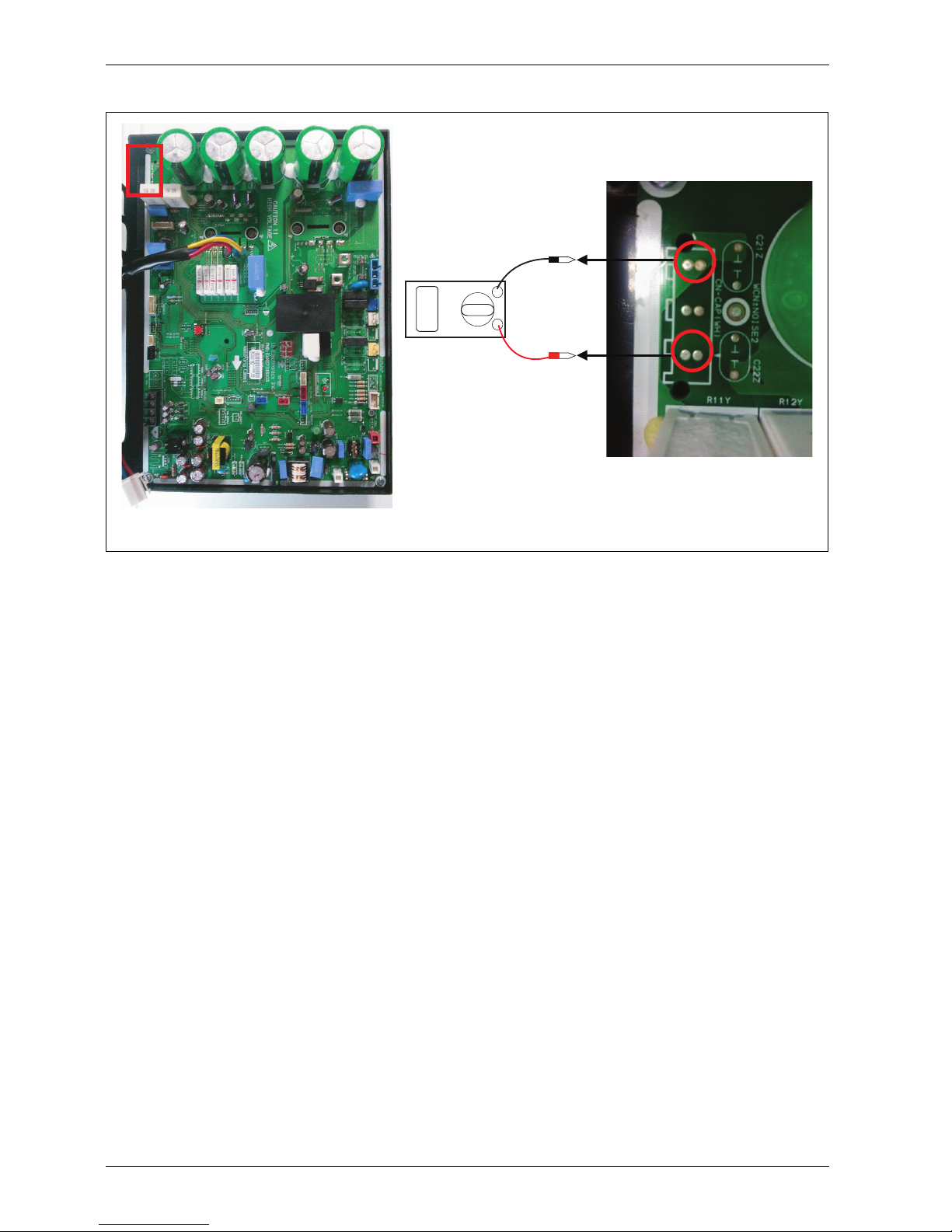
ODU Split 4, 6, 8
Fig. 17 ODU Split 4, 6, 8
[1] Short circuit check point
[2] After turning off the main power; R24N between the ends of the
resistance will be measured to 620~670
6 720 817 722-15.1I
1
2
Page 19

Error handling instructions for Split outdoor unit
Split ODU – 6 720 817 722 (2015/06)
19
ODU Split 11s/t, 13s/t, 15s/t
Fig. 18 ODU Split 11s/t, 13s/t, 15s/t
[1] ODU Split 11t/13t/15t
[2] ODU Split 11s/13s/15s
[3] Short circuit check point
6 720 817 722-16.1I
PT S R
N
U
N
V
N
W
1
2
3
Page 20

Error handling instructions for Split outdoor unit
Split ODU – 6 720 817 722 (2015/06)
20
2.8 Error code 29
2.8.1 Error diagnosis and countermeasure flow chart
Display
code
Title Cause of error
Check point & Normal
condition
29 Inverter
compressor
over
current
• 1~ODU:
inverter
compressor
input current
is 30A
• 3~ODU:
inverter
compressor
input current
is 24A
1. Overload operation (pipe
clogging/covering/EEV
defect/ refrigerant
overcharge)
2. Compressor damage
(insulation damage /
motor damage)
3. Input voltage low
4. ODU PCB assembly 1
damage
Table 15 Error code 29
Is installation condition
normal?
No -> 1. Check pipe clogging /
distortion
2. Check covering (outdoor unit)
3. Check EEV connector
assembly condition / normal
operation
4. Check refrigerant pressure
-->Reassemble or manage if
abnormality found
Yes
Are the resistance
between each phase
and insulation
resistance of inverter
compressor normal?
No ->
1. Check resistance between
each terminal of compressor
(0.188 7%
2. Check insulation resistance
between compressor terminal
and pipe (over 50 M)
--> Replace compressor if
abnormality is found
Yes
Is compressor wire
connection condition
normal?
No -> 1. Check PCB assembly 1 U,V,W
connector connection
condition
2. Check wire disconnection and
wiring
3. Check compressor terminal
connection condition (bad
contact)
--> Reassemble if abnormality is
found
Yes
Is input voltage normal? No -> 1. Check U-V, V-W, W-U phase is
220~240 V 10%
--> Check connection condition
and wiring if power is abnormal
Yes
Is PCB assembly 1
normal?
No -> 1. Check PCB assembly 1 IPM
normality
--> Replace inverter PCB assembly
Yes
Recheck power and
installation condition
Table 16 Error diagnosis and countermeasure chart
Page 21

Error handling instructions for Split outdoor unit
Split ODU – 6 720 817 722 (2015/06)
21
2.9 Error code 32
2.9.1 Error diagnosis and countermeasure flow chart
Inspecting inverter compressor discharge sensor
1. Set multi-tester to resistance measurement mode.
2. Measure the resistance between inverter discharge sensor
connector pins.
3. Measure resistance value of 200k10%, 25 °C basis.
4. Check if the sensor insulation is damaged, measure the resistance
between sensor connector pin and unit assembly pipe (1M or
more)
Fig. 19 CN_TH3 connector
[1] CN_TH3 (red 4pin connector)
Display
code
Title Cause of error
Check point & Normal
condition
32 High
temperatur
e in
discharge
pipe of the
inverter
compressor
• Overload
operation
(outdoor fan
constraint,
screened,
blocked
• Poor INV
comp
discharge
sensor
• LEV
connector
displaced /
poor LEV
assembly
1. Check outdoor fan
constraint / screened /
flow structure
2. Check refrigerant leakage
3. Check if the sensor is
normal
4. Check the status of EEV
assembly
Table 17 Error code 32
Is the heating water flow
sufficient?
No -> 1. Check that the heating water
circulation pump is working
2. Check that the heating water
flow rate is sufficient
3. Check preassure gauge
(1.5~2.5 bar)
-->Remove cause of error
Yes
Is there enough
refrigerant?
No -> 1. Check refrigerant leakage
2. Supply refrigerant if not
enough
Yes
Is the EEV properly
assembled?
No -> 1. Check the status of PCB
(inverter) EEV1 assembly
2. Check the status of EEV
assembly
3. Check PCB (inverter) IPM
input signal connectors shortcircuit
--> Refer to CH21 trouble
shooting method
Yes
Is the inverter
compressor sensor
normal?
No -> 1. Check the sensor assembly
status
2. Check if the sensor is broken:
measure resistance
200k10% (25 °C basis)
Table 18 Error diagnosis and countermeasure chart
6 720 817 722-17.1I
1
Page 22

Error handling instructions for Split outdoor unit
Split ODU – 6 720 817 722 (2015/06)
22
2.10 Error code 35
2.10.1 Error diagnosis and countermeasure flow chart
Display
code
Title Cause of error
Check point & Normal
condition
35 Low
pressure
error
• Excessive
decrease of
pressure
1. Defective low pressure
sensor
2. Defective unit fan
3. Deformation because of
damage of refrigerant
pipe
4. Defective unit EEV
5. Covering / clogging (unit
covering during cooling
mode / unit filter clogging
during heating mode)
6. SVC valve clogging
7. Defective unit PCB
(inverter)
8. Defective unit pipe sensor
Table 19 Error code 35
Are communication
cable / piping normal?
No -> 1. Check communication / piping
correction
Yes
Is amount of refrigerant
normal?
No -> 1. Check for pipe crack or trace of
refrigerant leakage
2. Weld / reconnect the cracked
portion
3. Adjust the amount of /
recharge refrigerant
Yes
Is the strainer OK?
1)
1) If the temperature difference between inlet and outlet of strainer is so large that
frost or ice formation can be seen or confirmed then clogging of strainer should
be checked (Notice: it is not full ice forming of strainer, in case that there is not at
inlet portion but at outlet portion)
No -> 1. Replace the strainer
Yes
Are the value of manifold
gauge and pressure
sensor the same?
(Is the low pressure
value actually low?)
No ->
1. Replace the pressure sensor
Yes
• Check unit LEV
• Check unit PCB
(inverter)
• Check unit
installation
conditions
Table 20 Error diagnosis and countermeasure chart
Page 23

Error handling instructions for Split outdoor unit
Split ODU – 6 720 817 722 (2015/06)
23
2.11 Error code 41, 44, 45, 46, 48
2.11.1 Error diagnosis and countermeasure flow chart
Fig. 20 Check sensor
[1] Unplugged; check the resistance (10k)
[2] Plugged; check the voltage (2.5V DC)
Display
code
Title Cause of error
Check point & Normal
condition
41 D-pipe
sensor
(inverter)
• Open / short
• Soldered
poorly
• Internal
circuit error
1. Bad connection of
thermistor connector
2. Defect of thermistor
connector (open / short)
3. Defect of outdoor PCB
(inverter)
44 Air sensor • Open / short
• Soldered
poorly
• Internal
circuit error
1. Bad connection of
thermistor connector
2. Defect of thermistor
connector (open / short)
3. Defect of outdoor PCB
(inverter)
45 Condenser
Mid-pipe
sensor
• Open / short
• Soldered
poorly
• Internal
circuit error
1. Bad connection of
thermistor connector
2. Defect of thermistor
connector (open / short)
3. Defect of outdoor PCB
(inverter)
46 Suction
pipe sensor
• Open / short
• Soldered
poorly
• Internal
circuit error
1. Bad connection of
thermistor connector
2. Defect of thermistor
connector (open / short)
3. Defect of outdoor PCB
(inverter)
48 Condenser
out-pipe
sensor
• Open / short
• Soldered
poorly
• Internal
circuit error
1. Bad connection of
thermistor connector
2. Defect of thermistor
connector (open / short)
3. Defect of outdoor PCB
(inverter)
Table 21 Error code 35
Is sensor connected to
PCB (inverter)
correctly?
No -> 1. Connect sensor to PCB
(inverter) correctly
Yes
Is sensor value correct? No -> 1. Replace sensor
Yes
• Replace
corresponding PCB
(inverter)
Table 22 Error diagnosis and countermeasure chart
V
6 720 817 722-18.1I
1 2
Page 24

Error handling instructions for Split outdoor unit
Split ODU – 6 720 817 722 (2015/06)
24
2.12 Error code 43
2.12.1 Error diagnosis and countermeasure flow chart
Fig. 21 HP sensor characteristics
[1] Pressure sensor
[2] High pressure sensor: 0~5 MPa, Vout 0.5~3.5 V
Display
code
Title Cause of error
Check point & Normal
condition
43 High
pressure
sensor
error
• Abnormal
value of
sensor (open
/ short)
1. Bad connection of
connector PCB (inverter)
2. Bad connection high
pressure connector
3. Defect of connector PCB
(inverter) (open/short)
4. Defect of PCB (inverter)
Table 23 Error code 43
Is pressure sensor OK? No -> 1. Replace the pressure sensor
Yes
Is sensor connected to
PCB (inverter)
correctly?
No -> 1. Connect sensor to PCB
(inverter) correctly
Yes
After replacement of
outdoor unit main PCB
(inverter) is the system
also abnormal?
No ->
END
Yes
• Replace
corresponding PCB
(inverter)
Table 24 Error diagnosis and countermeasure chart
1
2
6 720 817 722-22.1I
Page 25

Error handling instructions for Split outdoor unit
Split ODU – 6 720 817 722 (2015/06)
25
2.13 Error codes 52, 53
Fig. 22 Error codes 52, 53
2.13.1 Error code 52
Inverter PCB
Main/ODU PCB
CANboard
Installerboard
CH52
No Error
1
2
3
CH53
??
Situation Description
Error code that is sent to
Installerboard by CAN
Waiting time of
communication before
error is generated
1 No communication between
INV-PCB and ODU-PCB
(380V / 3~units)
CAN-PCB receives error
code from ODU-PCB but
Inverter-PCB does not
respond
52
30 seconds
2 No communication between
ODU-PCB and CAN-PCB
CAN-PCB does not receive
signals from ODU-PCB
53 10 seconds
3 No communication between
CAN-PCB and Installerboard
CAN-PCB does not send
signals to Installerboard
55 ODU shuts down after 1~3
seconds from recognizing
CAN communication error
Table 25 Error codes 52, 53
Display
code
Title Cause of error
Check point & Normal
condition
52 PCB
communica
tion error
• Checking the
communicati
on state
between
main PCB
and inverter
PCB
1. Generation of noise
source interfering with
communication
Table 26 Error code 52
Is transmission LED
(Yellow) of inverter
compressor PCB on?
No -> Is noise filter or fuse normal?
▶ NO: Replace noise filter or fuse
-or-
▶ YES: Replace inverter
compressor PCB
Yes
Is transmission cable
connected correctly?
No -> 1. Re-connect transmission cable
Yes
Is main PCB normal? No -> 1. Replace main PCB
Yes
• Replace inverter
compressor PCB
Table 27 Error diagnosis and countermeasure chart
Page 26

Error handling instructions for Split outdoor unit
Split ODU – 6 720 817 722 (2015/06)
26
ODU Split 11t, 13t, 15t
Check point
▶ Check the transmission connector and LED (main and inverter)
Fig. 23 Error code 52 check point ODU Split 11t/13t/15t
[1] Insufficient insertion of wires
[2] Damage of wire coating: Interference with wires or wire coating
damage with chopping
[3] 42/48/60k
[4] Inverter PCB
[5] Main PCB
OK NG
6 720 817 722-21.1I
1
2
3
4 5
Page 27

Error handling instructions for Split outdoor unit
Split ODU – 6 720 817 722 (2015/06)
27
2.13.2 Error code 53
Check point
1. Check the input power AC 230V
2. Check that the communication wires are correctly connected. Adjust
the connection of wire confirm the wire of “Live”, “Neutral”.
3. Check the resistance between communication line and GND (normal:
over 2M).
4. Check that the connector for communication is correctly connected.
5. Make sure you have connected to the communication line soldering
(if you do not connect by soldering, a communication error (CH05/
CH53) occurs by noise)
2.14 Error code 54
Fig. 24 Error code 54 diagnosis and countermeasure flow chart
[A] Items for checking
[B] Sub-items for checking
[1] Installation
[2] Fuse damage (R and S phases)
[3] Inverter PCB
[4] Checking N-phase
[5] Checking for power phase loss
[6] Checking for open and reverse phase
[7] AC load
2.15 Error code 60
Check point
▶ Check the EEPROM check sum and direction
Display code Title Cause of error Check point & Normal condition
53 Communication
PCB(Heater)
-->PCB(Inverter)
• Poor communication 1. Power input AC 230V
2. The connector for transmission is disconnected
3. The connection wires are miss-connected
4. The communication line is shorted at GND
5. Transmission circuit of PCB (inverter) is abnormal
6. Transmission circuit of PCB (heater) is abnormal
Table 28 Error code 53
Display
code
Title Cause of error
Check point & Normal
condition
54 Open and
reverse
phase error
• Prevention
of phase
unbalace and
prevention
of reverse
rotation of
constant rate
compressor
1. Main power wiring fault
Table 29 Error code 54
A
B
1
2
3
4 5
6
7
6 720 817 722-34.1I
Display
code
Title Cause of error
Check point & Normal
condition
60 PCB
(inverter)
and main
EEPROM
check sum
error
• EEPROM
access error
and check
sum error
1. EEPROM contact defect /
wrong insertion
2. Different EEPROM
version
3. ODU inverter and main
PCB assembly 1 damage
Table 30 Error code 60
Is EEPROM insertion
normal?
No -> 1. Check EEPROM insert
direction / connection
condition
2. Check EEPROM check sum
-->Replace if abnormality is found
Yes
Is PCB assembly 1
normal?
No -> 1. Replace PCB assembly 1
Yes
Is main PCB assembly 1
normal?
No -> 1. Replace main PCB assembly 1
Yes
• Recheck power and
installation condition
Table 31 Error diagnosis and countermeasure chart
Page 28

Error handling instructions for Split outdoor unit
Split ODU – 6 720 817 722 (2015/06)
28
Fig. 25 ODU Split 4/6/8
Fig. 26 ODU Split 11/13/15
[1] ODU Split 11s/13s/15s
[1] ODU Split 11t/13t/15t
6 720 817 722-23.1I
EEPROM
EEPROM
6 720 817 722-24.1I
1
2
Page 29

Error handling instructions for Split outdoor unit
Split ODU – 6 720 817 722 (2015/06)
29
2.16 Error code 61
2.16.1 Error diagnosis and countermeasure flow chart
Inspecting condenser pipe sensor
1. Set multi-tester as resistance measurement mode.
2. Measure the resistance between rated speed compressor discharge
sensor connector pins.
3. Measure resistance value of 5k 10% (25 °C basis).
4. Check if the sensor insulation is damaged --> measure the resistance
between sensor connector pin and unit assembly pipe 1M .
Fig. 27 CN-C/PIPE connector
[1] CN-C/PIPE (Violet 3Pin connector)
Display
code
Title Cause of error
Check point & Normal
condition
61 High
temperatur
e in
condenser
pipe
• Overload
operation
(outdoor fan
constraint,
screened,
blocked)
• Unit heat
exchanger
contaminate
d
• EEV
connector
displaced /
poor EEV
assembly
• Poor
condenser
pipe sensor
assembly /
broken
1. Check outdoor fan
constraint / screened /
flow structure
2. Check if refrigerant is
overcharged
3. Check the status of the
EEV assembly
4. Check the status of
sensor assembly
Table 32 Error code 61
Is the unit properly
installed?
No -> 1. Check fan locking
2. Remove blockings around heat
exchanger
3. Maintain distance between
unit and the wall
4. Check pipe folding and
abnormality
5. Check SVC lock
Yes
Is the refrigerant
properly charged?
No -> 1. Check if refrigerant is
overcharged
--> Adjust refrigerant volume
Yes
Is the EEV properly
assembled?
No -> 1. Check the status of PCB
(inverter) CN-EEV1 assembly
2. Check the status of EEV
assembly
--> Reassemble / replace if
abnormality is found
Yes
Is the condenser pipe
sensor normal?
No -> 1. Check the sensor assembly
status
2. Check if the sensor is burned:
measure resistance
-->5k 10% (25 °C basis)
Yes
Recheck power and
installation condition
Table 33 Error diagnosis and countermeasure chart
1
6 720 817 722-35.1I
Page 30

Error handling instructions for Split outdoor unit
Split ODU – 6 720 817 722 (2015/06)
30
2.17 Error code 62, 65
2.17.1 Error diagnosis and countermeasure flow chart
▶ Short circuit check: if temperature 130 °C
▶ Open circuit check: if temperature < – 30 °C
System will go in self diagnosis (error 65) is displayed and ODU stops.
Check point
1. Check resistance between no. 19 pin and no. 20 pin of PCB PFC
module
2. Resistance value should be in 7k 10% (at 25 °C).
Fig. 28 Error codes 62, 65 check the PFCM
Display code Title Cause of error Check point & Normal condition
62 Heat sink temp high • Heat sink sensor detected high
temperature (85 °C)
1. Part no. :EBR37798101~09
-Check the heat sink sensor: 10k at 25 °C (unplugged)
-Check the outdoor fan is running correctly
2. Part no. :EBR37798112~21
-Check the soldered condition in the 22, 23 pin of IPM,
PFCM
-Check the screw torque of IPM, PFCM
-Check the spreadable condition of thermal grease on IPM,
PFCM
-Check the outdoor fan is running correctly
65 Heat sink sensor • Connector connection error
• Faulty PCB
• Faulty sensor (Open / Short)
1. Normal resistor: 5k at 25 °C (unplugged)
2. Normal voltage: 2.5Vdc at 25 °C (plugged)
3. Refer to sensor resistance table
Table 34 Error code 61
Is there good screw
torque of IPM, PFCM?
No -> 1. Tighten the screw of IPM,
PFCM
Yes
Is there normal
resistance between 22
and 23 Pin of IPM,
PFCM?
Is there normal thermal
grease on IPM, PFCM?
Is IPM, PFCM normal?
No ->
1. Change the inverter PCB
Yes
Recheck power and
installation condition
Table 35 Error diagnosis and countermeasure chart
27 26 25 24 23 22 21
0.4 ~ 0.6 V
6 720 817 722-36.1I
Page 31

Error handling instructions for Split outdoor unit
Split ODU – 6 720 817 722 (2015/06)
31
Fig. 29 Error code 62, 65 check points
[1] ODU Split 4/6/8
[2] PFCM: measuring resistance between no. 19, 20 pin
[3] ODU Split 11s/13s/15s
[4] ODU Split 11t/13t/15t
[5] Heat sink temperature output pin
[IPM]
[PFCM]
1 2ྛ
1 2ྛ
6 720 817 722-25.1I
1
3
2
4
5
Page 32

Error handling instructions for Split outdoor unit
Split ODU – 6 720 817 722 (2015/06)
32
2.18 Error code 67
2.18.1 Error diagnosis and countermeasure flow chart
Check point
1. Check voltage between 1pin and 4pin of fan motor connector (tester
diode mode).
2. Voltage value should be in 1V 0.2V.
3. Do not replace all of fan motor and 220 – 240 V~at once.
4. Check error code again, after replacing the abnormal part (fan motor
or PCB) first.
Fig. 30 Error code 67
[1] Fan motor connector
Display code Title Cause of error Check point & Normal condition
67 Fan lock error • Fan RPM is 10 RPM or less for 5
seconds when ODU fan starts or
40 RPM or less after fan starting
1. ODU fan locking
2. Heat sink assembly of PCB assembly 1 condition abnormal
3. Defect of temperature sensing circuit part defect of PCB
(inverter)
Table 36 Error code 67
Is ODU fan motor
assembly condition
normal?
No ->
1. Check ODU fan motor
assembly condition and fan
locking
--> Reassemble or replace if
abnormality is found
Yes
Is ODU fan motor
normal?
No -> 1. Set the multi tester to diode
mode
2. Check voltage between 1pin
and 4pin of fan motor
(1 0.2V)
Yes
Is wire connection of
ODU fan motor wire
normal?
No -> 1. Check wiring between ODU fan
motor and PCB (inverter)
(Check if Hall sensor and
motor output terminal colour is
matched)
--> Reassemble if abnormality is
found
Yes
Is PCB assembly 1
normal?
No -> 1. Replace PCB assembly 1
Yes
Recheck power and
installation condition
Table 37 Error diagnosis and countermeasure chart
6 720 817 722-26.1I
1
Page 33

Error handling instructions for Split outdoor unit
Split ODU – 6 720 817 722 (2015/06)
33
Fig. 31 Error code 67 check points
[1] ODU Split 4/6/8
[2] ODU Split 11s/13s/15s
[3] ODU Split 11t/13t/15t
6 720 817 722-27.1I
2
3
1
Page 34

Check compressor resistances
Split ODU – 6 720 817 722 (2015/06)
34
3 Check compressor resistances
To check the resistance of the compressor:
▶ Disconnect the compressor motor plug
▶ Measure the resistance between each coil and ground
▶ The resistance should be more than 2M (at 20 °C)
To check the resistance between the coils:
▶ Disconnect the compressor motor plug
▶ Measure the resistance between the coils
▶ The resistance should be equal
Fig. 32 Check compressor resistances
[1] Compressor
[2] Copper pipe
WARNING: Electric shock!
▶ Even if the ODU is disconnected from power supply,
it takes some time to discharge the remaining
electricity of the electrolytic capacitor. Before
conducting a service or repairing job, switch off the
main power supply and make sure that all LED on the
circuit boards are off.
1
2
1
6 720 817 722-33.1I
Page 35

Compressor replacement
Split ODU – 6 720 817 722 (2015/06)
35
4 Compressor replacement
1. Disconnect the unit from power supply.
2. Detach the motor plug from the compressor.
3. Remove the sound proof covering the faulty compressor.
4. Pump out the refrigerant completely.
5. Disconnect the brazing sections of the suction pipe by using brazing
torch.
6. Remove the three nuts at cushion rubber section to take out the
faulty compressor outside the unit.
7. Install the new compressor in the unit. Be sure to insert the cushion
rubbers before tightening the fixing nuts of the compressor.
8. Remove the rubber caps put on the suction and discharge pipes of
the new compressor to release the sealing nitrogen gas.
9. Braze the suction and discharge pipe to the compressor with brazing
torch.
10.Conduct air tight test to check that the piping system is free from
leakage.
11.Re-connect the power cable to the terminal board of the
compressor.
12.Attach the sound-proof covering to the compressor.
13.Conduct vacuum suction.
14.After completion of vacuum, open the service valves.
15.Charge the unit with the correct amount of refrigerant.
Fig. 33 Compressor replacement
[1] Insert the sound proof counter-clockwise
[2] Suction pipe
[3] Discharge pipe
2
3
1
6 720 817 722-30.1I
Page 36

Check system parameters
Split ODU – 6 720 817 722 (2015/06)
36
5 Check system parameters
6 Electronic expansion valve
Fig. 34 EEV driving circuit
Output pulse sequence
– In valve close state: 1 -->2 -->3 -->4 -->5 -->6 -->7 -->8 -->1
– In valve open state: 8 -->7 -->6 -->5 -->4 -->3 -->2 -->1 -->8
1. If EEV open angle does not change, all of output phase will be OFF.
2. If output phase is different or continuously in the ON state, motor will
not operate smoothly and start vibrating.
Temperature difference between inlet and outlet
depends on water flow rate and exchange-surface of the
heating system.
Symptom Remark
No temperature difference between water inlet and outlet
Power consumption is low (<80% of rated current)
Refrigerant completely leaked
Check cycle
Temperature difference is ok (5-10K)
Power consumption is low (<80% of rated current)
Leakage of refrigerant or clog of cycle
Defective compressor
Temperature difference is ok (5-10K)
Power consumption is high (over rated current)
Too much refrigerant
Temperature difference is ok (5-10K)
Power consumption is in range of rated current (10%)
Normal operation
Table 38 Temperature difference and power consumption
Suction pressure Outlet temperature Reason Result
Higher than normal value Higher than normal value Defective compressor
Defective 4-way-valve
Current is low
Normal value
Too much refrigerant High pressure does not quickly
increase when compressor starts
Lower than normal value Higher than normal value Insufficient amount of refrigerant
(leakage) or clogging
Current is low
Table 39 Pressure and temperature
6 720 817 722-37.1I
Output (Ø ) No. Output state
1 2 3 4 5 6 7 8
Ø 1 ON OFF OFF OFF OFF OFF ON ON
Ø 2 ON ON ON OFF OFF OFF OFF OFF
Ø 3 OFF OFF ON ON ON OFF OFF OFF
Ø 4 OFF OFF OFF OFF ON ON ON OFF
Table 40 Pulse signal output value and valve operation
Page 37

Electronic expansion valve
Split ODU – 6 720 817 722 (2015/06)
37
EEV valve operation
Fig. 35 EEV valve operation
[A] Valve open angle
[P] Pulse
[1] Close
[2] Open
[3] Fully open 1350 pulses
• At power ON, open angle signal of 1400 pulses output and valve
position is set to
If valve operates smoothly, no noise and vibration occur and if valve
is closed. Noise occurs.
• Noise from the EEV can be confirmed by touching the EEV surface
with a screw driver and listening to the EEV noise.
• If liquid refrigerant is in EEV, the noise is lower.
EEV failure check method
2
3
a
1
A
P
6 720 817 722-31.1I
a
Failure mode Diagnosis Repair process Remark
Microcomputer driving circuit
failure
1. Disconnect the EEV connector from
control board and connect testing
LED
2. Main power ON, pulse signal is out
from EEV for 17 seconds. If the LEDs
do not turn on, or are in on state
continuously, then the driving circuit
is abnormal
Check and replace unit control
board
Unit
EEV locking 1. If EEV is locked, in no load state, the driving motor rotate
and clicking sound always occurs
Replace EEV
EEV motor coil short or
misconnection
1. Check the resistance between coil terminal (red-white, redyellow, red-orange, red-blue)
2. If the estimated resistance value is in 52 3 then the EEV
is normal
Replace EEV
1. Check the resistance between coil terminal (brown-white,
brown-yellow, brown-orange, brown-blue)
2. If the estimated resistance value is in 150 10 then the
EEV is normal
Replace EEV
Table 41 EEV failure check method
1K LED
Page 38

Fan motor
Split ODU – 6 720 817 722 (2015/06)
38
Remove and assemble the EEV coil
Fig. 36 Remove and assemble the EEV coil
[1] Remove
[2] Assemble
[3] A part
▶ Grip the A part tightly, and pull coil part upward.
Fig. 37
7 Fan motor
2
1
3
6 720 817 722-32.1I
Checking item Symptom Countermeasure
1. The fan motor does not operate.
Does failure appear again when starting
operation?
2. Large vibration of the fan motor.
1. When power supply is abnormal
• Modify connection status in front or at the
rear of the breaker, or if the power terminal
console are at frosting condition.
• Modify the power supply voltage if it is
beyond specified scope.
2. For wrong wiring
-For following wiring
1. Check connection status.
2. Check contact of the connector.
3. Check that parts are firmly secured by
tightening screws.
4. Check connection of polarity.
5. Check short circuit and grounding.
6. For failure of motor
• Measure winding resistance of the motor
coils.
7. For failure of circuit board
Replace the circuit board in following
procedures if problems occur again when
powering on and if there are no matters
equivalent to items as specified in above 1)
through 4).
Carefully check both connector and grounding
wires when replacing the circuit board.
1. Replace only fan control boards.
If the fan starts, it means that the fan control
board is defect.
2. Replace both fan control board and the main
board.
If the fan starts, it means that the main board
is defect.
Table 42 Fan motor check
Page 39

Replacement procedure for INV PCB
Split ODU – 6 720 817 722 (2015/06)
39
8 Replacement procedure for INV PCB
1. Disconnect the unit from power supply.
2. Disassemble main PCB by unscrewing 2 screws (Figure 1).
3. Disassemble panel assembly (with cooling fan) by unscrewing for
screws (Figure 2).
4. Replace INV PCB assembly (Figure 3). When assembling new INV
PCB assembly with control case, make sure that PCB case is inserted
surely in the slit of control case. Confirm that there is no gap between
INV PCB case and control case (Figure 4).
5. Re-assemble panel assembly and main PCB.
Fig. 38 Replacement of INV PCB
CAUTION: Be sure that INV PCB assembly is firmly
assembled with control case.
If any gap is present, it will cause product malfunction.
▶ Confirm that there is no gap between INV PCB case
and control case (Figure 4).
> .2-2 erugiF <> .1-2 erugiF <
> .4 erugiF <> .2-3 erugiF <> .1-3 erugiF <
< Figure 1. >
6 720 817 722-39.1I
Page 40

Replacement procedure for INV PCB
Split ODU – 6 720 817 722 (2015/06)
40
Fig. 39 INV PCB fan motor connection
[1] Fan motor wire terminal (UP)
[2] Fan motor wire terminal (DOWN)
[3] Main PCB case
[4] To Fan motor
[5] To Fan motor
Attention! After replacing the INV PCB assembly, make
sure that connection of the fan motor wires is correct.
YELLOW
RED
YELLOW
RED
YELLOW
RED
YELLOW
RED
INV. PCB
UP
DOWN
UP
DOWN
2
3
1
5
4
6 720 817 722-40.1I
Page 41

Other pre - checkings
Split ODU – 6 720 817 722 (2015/06)
41
9 Other pre - checkings
▶ Check blockage of refrigerant circuit
Are both check - valves completely open?
▶ Check function of fans
– Check rotation speed
– Check supply voltage
▶ Check function of water pump
– Check rotation speed
– Check supply voltage
▶ Check heat-transfer
– Clean heat-exchangers
▶ Check refrigerant charge
– Sub-cooling very high --> Overfilled
– Refill refrigerant (with gauge)
Page 42

Other pre - checkings
Split ODU – 6 720 817 722 (2015/06)
42
 Loading...