

Bosch NWD-455V03-20P, NWD-455VO3-10P, NWD-455V04-10P, PNWD-455V03-20P, NWD-455V04-20P Operating Instructions Manual
FlexiDome IP
NWD-455VO3-10P | NWD-455V04-10P | PNWD-455V03-20P |
NWD-455V04-20P
en Operating Instructions


FlexiDome IP | en 3
Table of Contents
1 Introduction 15
1.1 Type number overview 16
1.2 Unpacking 16
1.3 System requirements 17
1.4 Overview of functions 17
1.4.1 Wide dynamic range 18
1.4.2 Power-over-Ethernet 18
1.4.3 Receiver 18
1.4.4 Video encoding 18
1.4.5 Tri Streaming 18
1.4.6 Recording 18
1.4.7 Multicast 19
1.4.8 Encryption 19
1.4.9 Configuration 19
1.4.10 Tampering recognition and motion detectors 19
1.4.11 Snapshots 19
1.4.12 Backup 19
1.4.13 Intelligent Video Motion Detection 20
2 Disassembly 21
3 Mounting the unit 22
3.1 Attach the mounting plate 23
3.2 Make the connections 23
3.2.1 Power connection 24
3.2.2 Network (and PoE) connection 24
3.3 Mount the camera 24
4Camera set-up 25
4.1 Camera positioning 25
4.2 Focal length and focus 26
4.3 Basic settings 26
4.3.1 Install menu 27
Bosch Security Systems Operating Instructions V 1.0 | 2006.12

4 en | FlexiDome IP
4.3.2 Defaults 28
4.4 Closing the unit 28
5Network connection 29
5.1 System requirements 29
5.2 Establishing the connection 29
5.3 Secured network 31
6 Operation via the browser 32
6.1 Livepage 32
6.1.1 Processor load 32
6.1.2 Image selection 33
6.1.3 System log / Event log 33
6.1.4 Saving snapshots 33
6.1.5 Recording video sequences 33
6.1.6 Running recording program 34
6.2 Recordings page 35
6.2.1 Selecting recordings 35
6.2.2 Controlling playback 36
7 Configuration via the browser 39
7.1 Settings 39
7.2 General Settings 41
7.2.1 Camera identification 41
7.2.2 Password protection 41
7.2.3 Language selection 43
7.2.4 Date and time 43
7.2.5 Time server 43
7.3 Display Settings 45
7.3.1 Display stamping 45
7.4 Encoder Settings 46
7.4.1 Selecting an encoder profile 46
7.4.2 Changing profiles 48
7.4.3 JPEG posting 51
7.5 Camera settings 52
7.5.1 ALC 53
V 1.0 | 2006.12 Operating Instructions Bosch Security Systems

FlexiDome IP | en 5
7.5.2 Enhance 54
7.5.3 Color 55
7.5.4 Installer options 56
7.6 Recording 56
7.6.1 Type 57
7.6.2 Storage information 57
7.7 iSCSI settings 58
7.7.1 iSCSI IP address 58
7.7.2 iSCSI LUN map 59
7.7.3 Target IP address 59
7.7.4 Target node 59
7.7.5 Target LUN 59
7.7.6 Target password 59
7.7.7 Initiator name 60
7.7.8 Initiator extension 60
7.7.9 Decoupling the drive used 60
7.7.10 Storage information 60
7.8 Partitioning 61
7.8.1 Creating a partition 61
7.8.2 Partition status 63
7.8.3 Editing a partition 63
7.8.4 Deleting partitions 66
7.9 Recording profile 66
7.10 Recording scheduler 69
7.10.1 Activating recording 70
7.10.2 Recording status 71
7.11 Alarm Settings 71
7.11.1 Alarm connections 71
7.12 VCA 74
7.12.1 Analysis 74
7.12.2 Analysis type 75
7.12.3 Motion detector 75
7.12.4 Sensitivity 75
7.12.5 Tamper detection 77
7.13 Alarm e-mail 79
7.13.1 Send alarm e-mail 79
7.13.2 Mail server IP address 79
Bosch Security Systems Operating Instructions V 1.0 | 2006.12

6 en | FlexiDome IP
7.13.3 Layout 79
7.13.4 Destination address 80
7.13.5 Sender name 80
7.13.6 Send e-mail for testing 80
7.14 Service Settings 81
7.14.1 Network 81
7.14.2 Multicasting 84
7.14.3 Encryption 86
7.14.4 Version information 87
7.14.5 Livepage configuration 88
7.14.6 Licenses 90
7.14.7 Maintenance 91
7.15 Function test 93
8 Connections between video servers 94
8.0.1 Installation 94
8.0.2 Establishing the connection 94
8.0.3 Connect on alarm 94
8.0.4 Connecting with a Web browser 95
8.0.5 Closing the connection 95
9 Operation with decoder software 96
10 Maintenance 97
10.1 Testing the network connection 97
10.2 Repairs 97
10.2.1 Transfer and disposal 97
11 Troubleshooting 98
12 Specifications 100
12.1 Dimensions (mm/inch) 102
12.2 Accessories 102
12.2.1 Power transformers 102
V 1.0 | 2006.12 Operating Instructions Bosch Security Systems

FlexiDome IP | en 7
13 Glossary 103
Bosch Security Systems Operating Instructions V 1.0 | 2006.12

8 en | FlexiDome IP
Important safety instructions
Read, follow, and retain all of the following safety instructions.
Heed all warnings on the unit and in the operating instructions
before operating the unit.
1. Cleaning - Unplug the unit from the outlet before cleaning.
Follow any instructions provided with the unit. Generally,
using a dry cloth for cleaning is sufficient, but a moist flufffree cloth or leather shammy may also be used. Do not use
liquid cleaners or aerosol cleaners.
2. Heat Sources - Do not install the unit near any heat sources
such as radiators, heaters, stoves, or other equipment
(including amplifiers) that produce heat.
3. Water - Do not use this unit near water, for example near a
bathtub, washbowl, sink, laundry basket, in a damp or wet
basement, near a swimming pool, in an unprotected outdoor installation, or in any area classified as a wet location.
To reduce the risk of fire or electrical shock, do not expose
this unit to rain or moisture.
4. Object and liquid entry - Never push objects of any kind
into this unit through openings as they may touch dangerous voltage points or short-out parts that could result in a
fire or electrical shock. Never spill liquid of any kind on the
unit. Do not place objects filled with liquids, such as vases
or cups, on the unit.
5. Controls adjustment - Adjust only those controls specified
in the operating instructions. Improper adjustment of
other controls may cause damage to the unit. Use of controls or adjustments, or performance of procedures other
than those specified, may result in hazardous radiation
exposure.
6. Overloading - Do not overload outlets and extension cords.
This can cause fire or electrical shock.
7. Power cord and plug protection - Protect the plug and
power cord from foot traffic, being pinched by items
placed upon or against them at electrical outlets, and its
exit from the unit. For units intended to operate with
V 1.0 | 2006.12 Operating Instructions Bosch Security Systems

FlexiDome IP | en 9
230 VAC, 50 Hz, the input and output power cord must
comply with the latest versions of IEC Publication 227 or
IEC Publication 245. For outdoor use the power cord must
comply to NEC400-4 (CEC Rule 4-010) and marked with
OUTDOOR, W, or W-A.
8. Power sources - Operate the unit only from the type of
power source indicated on the label. Before proceeding,
be sure to disconnect the power from the cable to be
installed into the unit.
– For battery powered units, refer to the operating
instructions.
– For external power supplied units, use only the rec-
ommended or approved power supplies.
–For limited power source units, this power source
must comply with EN60950. Substitutions may damage the unit or cause fire or shock.
– For 24 VAC units, voltage applied to the unit's power
input should not exceed 28 VAC. User-supplied wiring
must comply with local electrical codes (Class 2
power levels). Do not ground the supply at the terminals or at the unit's power supply terminals.
– If unsure of the type of power supply to use, contact
your dealer or local power company.
9. Servicing - Do not attempt to service this unit yourself.
Opening or removing covers may expose you to dangerous
voltage or other hazards. Refer all servicing to qualified
service personnel.
10. Damage requiring service - Unplug the unit from the main
AC power source and refer servicing to qualified service
personnel when any damage to the equipment has
occurred, such as:
– the power supply cord or plug is damaged;
– exposure to moisture, water, and/or inclement
weather (rain, snow, etc.);
– liquid has been spilled in or on the equipment;
– an object has fallen into the unit;
– unit has been dropped or the unit cabinet is damaged;
Bosch Security Systems Operating Instructions V 1.0 | 2006.12

10 en | FlexiDome IP
– unit exhibits a distinct change in performance;
– unit does not operate normally when the user cor-
rectly follows the operating instructions.
11. Replacement parts - Be sure the service technician uses
replacement parts specified by the manufacturer, or that
have the same characteristics as the original parts. Unauthorized substitutions may cause fire, electrical shock, or
other hazards.
12. Safety check - Safety checks should be performed upon
completion of service or repairs to the unit to ensure
proper operating condition.
13. Installation - Install in accordance with the manufacturer's
instructions and in accordance with applicable local codes.
14. Attachments, changes, or modifications - Only use attachments/accessories specified by the manufacturer. Any
change or modification of the equipment, not expressly
approved by Bosch, could void the warranty or, in the case
of an authorization agreement, authority to operate the
equipment.
V 1.0 | 2006.12 Operating Instructions Bosch Security Systems
FlexiDome IP | en 11
DANGER! High risk:
This symbol indicates an imminently hazardous situation such
as "Dangerous Voltage" inside the product.
If not avoided, this will result in an electrical shock, serious
bodily injury, or death.
WARNING! Medium risk:
!
!
i
Indicates a potentially hazardous situation.
If not avoided, this could result in serious bodily injury or death.
CAUTION!
Indicates a potentially hazardous situation.
If not avoided, this may result in minor or moderate injury.
Alerts the user to important instructions accompanying the
unit.
NOTICE!
This symbol indicates information or a company policy that
relates directly or indirectly to the safety of personnel or
protection of property.
Bosch Security Systems Operating Instructions V 1.0 | 2006.12
12 en | FlexiDome IP
CAUTION!
– Camera Grounding - For mounting the camera in poten-
tially damp environments, ensure to ground the system
using the ground connection of the power supply connector (see section: Connecting external power supply).
– U.S.A. models only - Section 810 of the National Electrical
Code, ANSI/NFPA No.70, provides information regarding
proper grounding of the mount and supporting structure,
grounding of the coax to a discharge unit, size of grounding
conductors, location of discharge unit, connection to
grounding electrodes, and requirements for the grounding
electrode.
!
– Permanently connected equipment - Incorporate a readily
accessible disconnect device in the building installation
wiring.
– PoE - Never supply power via the Ethernet connection
(PoE) when power is already supplied via the power connector.
– Pole power switch - Incorporate an all-pole power switch,
with a contact separation of at least 3 mm in each pole,
into the electrical installation of the building.
– Power lines - Do not locate the camera near overhead
power lines, power circuits, or electrical lights, nor where
it may contact such power lines, circuits, or lights.
Video loss
Video loss is inherent to digital video recording; therefore,
Bosch Security Systems cannot be held liable for any damage
that results from missing video information. To minimize the
risk of lost digital information, Bosch Security Systems recommends multiple, redundant recording systems, and a procedure
to back up all analog and digital information.
V 1.0 | 2006.12 Operating Instructions Bosch Security Systems

FlexiDome IP | en 13
FCC & ICES Information
(U.S.A. and Canadian Models Only)
This equipment has been tested and found to comply with the
limits for a Class B digital device, pursuant to part 15 of the
FCC Rules. These limits are designed to provide reasonable protection against harmful interference in a residential installation.
This equipment generates, uses, and can radiate radio frequency energy and, if not installed and used in accordance with
the instructions, may cause harmful interference to radio communications. However, there is no guarantee that interference
will not occur in a particular installation. If this equipment does
cause harmful interference to radio or television reception,
which can be determined by turning the equipment off and on,
the user is encouraged to try to correct the interference by one
or more of the following measures:
– reorient or relocate the receiving antenna;
– increase the separation between the equipment and
receiver;
– connect the equipment into an outlet on a circuit dif-
ferent from that to which the receiver is connected;
– consult the dealer or an experienced radio/TV techni-
cian for help.
Disclaimer
Underwriter Laboratories Inc. ("UL") has not tested the performance or reliability of the security or signaling aspects of this
product. UL has only tested fire, shock and/or casualty hazards
as outlined in UL's Standard(s) for Safety for Information Tech-
nology Equipment, UL 60950-1. UL Certification does not cover
the performance or reliability of the security or signaling
aspects of this product.
UL MAKES NO REPRESENTATIONS, WARRANTIES, OR CERTIFICATIONS WHATSOEVER REGARDING THE PERFORMANCE OR
RELIABILITY OF ANY SECURITY OR SIGNALING RELATED FUNCTIONS OF THIS PRODUCT.
Bosch Security Systems Operating Instructions V 1.0 | 2006.12

14 en | FlexiDome IP
Disposal
Your Bosch product was developed and manufactured with
high-quality material and components that can be recycled and
reused. This symbol means that electronic and electrical appliances, which have reached the end of their working life, must
be collected and disposed of separately from household waste
material. Separate collecting systems are usually in place for
disused electronic and electrical products.
Please dispose of these units at an environmentally compatible
recycling facility, per European Directive 2002/96/EC.
Environmental statement - Bosch has a strong commitment
towards the environment. This unit has been designed to
respect the environment as much as possible.
For additional information, please contact the Bosch Security
Systems location nearest you or visit our web site at
www.boschsecuritysystems.com
V 1.0 | 2006.12 Operating Instructions Bosch Security Systems

FlexiDome IP Introduction | en 15
1 Introduction
The FlexiDome IP camera is a small, discreet, high-security surveillance dome containing a high-performance 1/3-inch CCD
color camera with integral varifocal lens. The integrated unit is
mounted to a wall or ceiling. The sturdy construction and high
impact resistant polycarbon dome protect the camera module
from damage.
The smart camera incorporates advanced digital signal processing for outstanding picture performance. The integrated camera
unit operates as a network video server and transmits video and
control signals over data networks such as Ethernet LANs and
the Internet.
The FlexiDome IP camera is easy to install and ready to use, and
offers the best solution for demanding scene conditions. Features include:
– Impact-resistant dome
– Tamper-resistant housing
– Intelligent Video Motion Detection (iso enhanced)
– Video and data transmission over IP data networks
– Tri Streaming function for simultaneous encoding with
three individually definable profiles
– Multicast function for simultaneous picture transmission to
multiple receivers
– Video encoding using international MPEG-4 standard
– Integrated Ethernet interface (10/100 Base-T)
– Configuration and remote control of all built-in functions
via TCP/IP and secure HTTPS
– Password protection to prevent unauthorized connection
or configuration changes
– Event-driven, automatic connection
– Convenient maintenance via uploads
– Flexible control and data channel encryption
– Authentication according to the 802.1x standard
–NightSense
TM
extends the camera’s low-light performance.
Bosch Security Systems Operating Instructions V 1.0 | 2006.12
16 en | Introduction FlexiDome IP
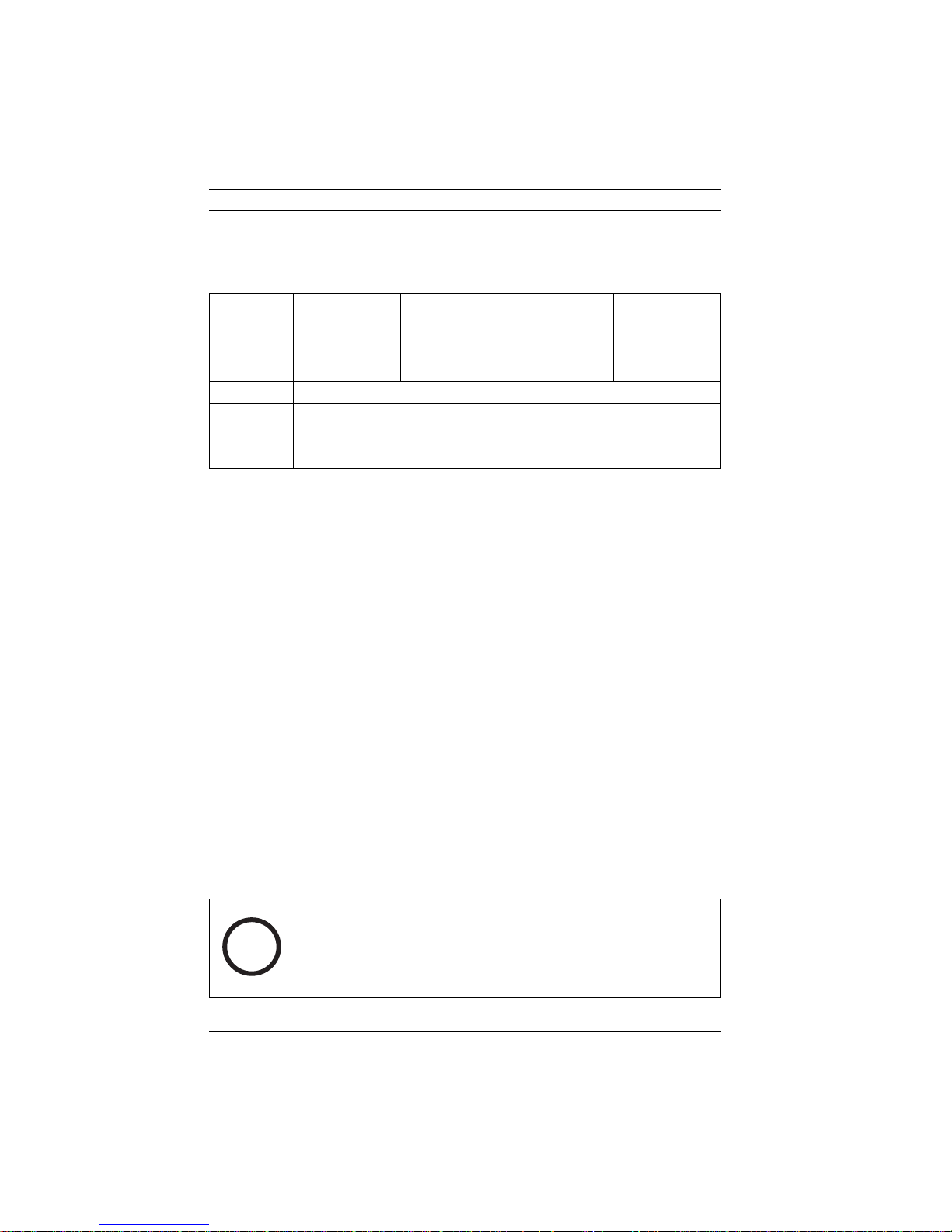
1.1 Type number overview
Type number NWD-455V03-10P NWD-455V04-10P NWD-455V03-20P NWD-495V04-20P
Lens Varifocal
2.6 to 6 mm
F1.4
Standard PAL NTSC
Supply volt-
age
24 VAC, 50 Hz or +12 VDC
(use class 2 power supply) or
PoE (IEEE 802.3af)
Table 1.1 FlexiDome IP type numbers
Varifocal
3.7 to 12 mm
F1.6
Varifocal
2.6 to 6 mm
F1.4
24 VAC, 60 Hz or +12 VDC
(use class 2 power supply) or
PoE (IEEE 802.3af)
Varifocal
3.7 to 12 mm
F1.6
1.2 Unpacking
Unpack carefully and handle the equipment with care. The
packaging contains:
– Integrated FlexiDome IP camera unit
– Mounting hardware kit
– Special screwdriver bit for tamper-resistant screws
– Lens adjustment cap
–CD ROM
–Manual
– System requirements
– Configuration Manager
–MPEG ActiveX control
–DirextX control
– Microsoft Internet Explorer
–Sun JVM
– Player and archive player
– Adobe Acrobat Reader
NOTICE!
If equipment appears to have been damaged during shipment,
i
repack it in the original packaging and notify the shipping agent
or supplier.
V 1.0 | 2006.12 Operating Instructions Bosch Security Systems
FlexiDome IP Introduction | en 17
1.3 System requirements
– Computer with Windows 2000/XP operating system, net-
work access and Microsoft Internet Explorer web browser
version 6.0 or later
or
– Computer with Windows 2000/XP operating system, net-
work access and reception software, for example VIDOS,
BMVS or DIBOS 8.0
or
– MPEG-4 compatible hardware decoder from
Bosch Security Systems (such as VIP XD) as a receiver and
a connected video monitor
The minimum PC requirements are:
– Operating platform: a PC running Windows 2000 or Win-
dows XP with IE6.0
– Processor:1.8 GHz Pentium IV
– RAM memory: 256 MB
– Video system: 128 MB video memory, 1024x768 display
with 24-bit color
– Network interface: 100-BaseT
–DirectX: 9.0b
NOTICE! Make sure the graphics card is set to 16-bit or 32-bit
color depth and that Sun JVM is installed on your PC. To play
back live video images, an appropriate MPEG ActiveX must be
i
installed on the computer. If necessary, install the required
software and controls from the product CD provided. If you
need further assistance, contact your PC system administrator.
1.4 Overview of functions
The integrated camera unit incorporates a network video
server. Its primary function is to encode video and control data
for transmission over an IP network. With its MPEG-4 encoding
it is bandwidth efficient for both network and recording. The
use of existing networks means that integration with CCTV systems or local networks can be achieved quickly and easily.
Bosch Security Systems Operating Instructions V 1.0 | 2006.12

18 en | Introduction FlexiDome IP
Video images from a single camera can be simultaneously
received on several receivers.
1.4.1 Wide dynamic range
The digital signal is automatically processed to optimally capture the detail in both the high and low light areas of the scene
simultaneously, maximizing the information visible in the picture.
1.4.2 Power-over-Ethernet
Power for the camera can be supplied via a Power-over-Ethernet (IEEE 802.3af) compliant network cable connection. With
this configuration, only a single cable connection is required to
view, power and control the camera.
1.4.3 Receiver
MPEG-4 compatible hardware decoders (for example VIP XD)
can be used as a receiver. Computers with decoding software
such as VIDOS or computers with the Microsoft Internet
Explorer web browser installed can also be used as receivers.
1.4.4 Video encoding
The camera uses the MPEG-4 compression standard. Thanks to
efficient encoding, the data rate remains low even with high
image quality and can also be adapted to local conditions
within wide limits.
1.4.5 Tri Streaming
Tri Streaming allows the incoming data stream to be encoded
simultaneously according to three different, individually customized profiles. This creates two MPEG4 streams per camera
that can serve different purposes, for example, one for local
recording and one optimized for transmission over the LAN, and
an additional JPEG stream for use with a PDA.
1.4.6 Recording
The camera can be used with an iSCSI server connected via the
network to store long-term recordings.
V 1.0 | 2006.12 Operating Instructions Bosch Security Systems

FlexiDome IP Introduction | en 19
1.4.7 Multicast
In suitably configured networks, the multicast function enables
simultaneous, real time transmission to multiple receivers. The
prerequisite for this is that the UDP and IGMP V2 protocols are
implemented on the network.
1.4.8 Encryption
The data transmissions and the authentication channel can be
encrypted to prevent unauthorized access. Web browser connections can be protected using HTTPS.
1.4.9 Configuration
The camera can be configured using a browser on the local network (Intranet) or from the Internet. Similarly, firmware
updates and rapid loading of device configurations are also possible. Configuration settings can be stored as files on a computer and copied from one camera to another.
1.4.10 Tampering recognition and motion detectors
The camera offers a wide range of configuration options for
alarm signaling in the event of tampering with the camera. An
algorithm for detecting movement in the video image is also
part of the scope of delivery and can optionally be extended to
include special video analysis algorithms.
1.4.11 Snapshots
Individual video frames (snapshots) can be called up as JPEG
images, stored on the hard drive or displayed in a separate
browser window.
1.4.12 Backup
The browser application Livepage has an icon for saving the
video images provided by the unit as a file on your computer's
hard drive. Clicking this icon stores the video sequences and
they can be replayed with the Player from
Bosch Security Systems included with the package.
Bosch Security Systems Operating Instructions V 1.0 | 2006.12

20 en | Introduction FlexiDome IP
1.4.13 Intelligent Video Motion Detection
The intelligent video motion detection (iVMD) system of the
camera uses advanced analysis algorithms with comprehensive
functions for the detection of motion.
V 1.0 | 2006.12 Operating Instructions Bosch Security Systems
FlexiDome IP Disassembly | en 21
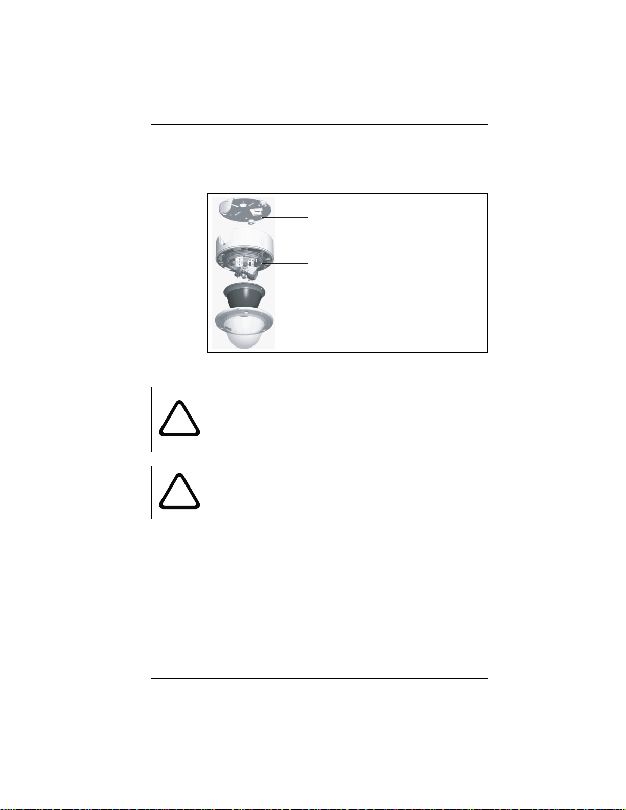
2 Disassembly
The camera/housing unit consists of the following parts:
Mounting plate
Camera module and mounting base
Inner liner
Trim ring and dome
Fig. 2.1 Exploded view
CAUTION!
Installation should only be performed by qualified service
!
personnel in accordance with the National Electrical Code or
applicable local codes.
CAUTION!
!
Bosch Security Systems Operating Instructions V 1.0 | 2006.12
The camera module is a sensitive device and must be handled
carefully. Do not drop when disassembling the unit.
To disassemble the unit proceed as follows:
1. Using the special screwdriver bit, loosen the three tamper-
resistant screws in the trim ring (the screws remain in
place).
2. Remove the trim ring with dome by pulling it off of the
base.
3. Remove the inner liner by pulling it off of the base.
4. Loosen the three Phillips captive screws until the mount-
ing plate separates from the body
22 en | Mounting the unit FlexiDome IP
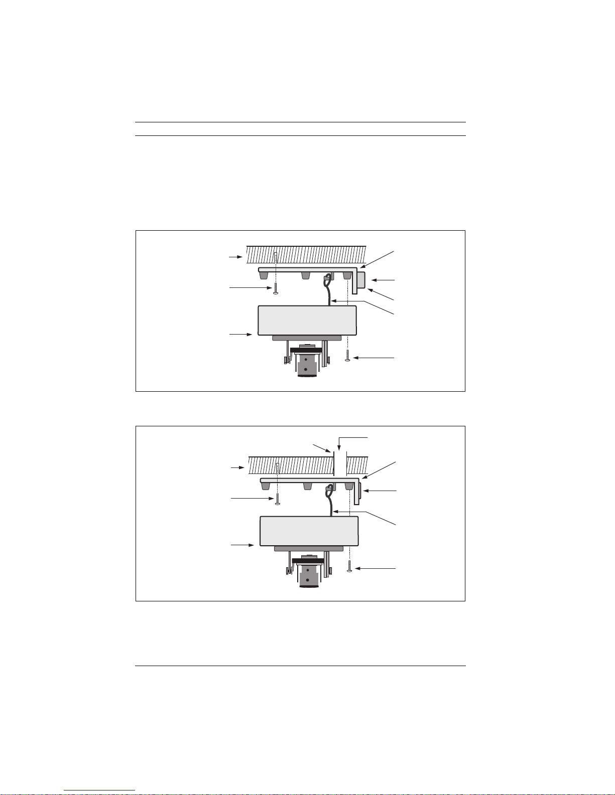
3 Mounting the unit
The unit may be surface mounted in two different ways depending on whether the connection is via the top or the side. Refer
to the dimensions drawing to find the exact position of the
screw holes and the entry hole for the wires.
Mounting plate
Solid surface (three
pre-drilled 8mm holes)
Three screws (supplied
with camera)
Integrated camera unit
and base
Fig. 3.1 Surface mounting - side connection
Wires
Conduit
Suspension wire
Three screws
(M5, supplied)
Conduit
Solid surface (three
pre-drilled 8mm holes)
Three screws (supplied
with camera)
Integrated camera unit
and base
Fig. 3.2 Surface mounting - top connection
V 1.0 | 2006.12 Operating Instructions Bosch Security Systems
Wires
Mounting plate
Cap
Suspension wire
Three screws
(M5, supplied)
FlexiDome IP Mounting the unit | en 23
3.1 Attach the mounting plate
1. Use the mounting plate as a drilling template to drill three
holes in the mounting surface.
2. Use the supplied plugs and screws to attach the mounting
plate to the surface.
3. With a rear connection, leave the cap in place. With a side
connection:
a. remove the cap covering the side entrance;
b. attach a 22 mm / ½ inch (PG16) gland conduit to the
mounting plate.
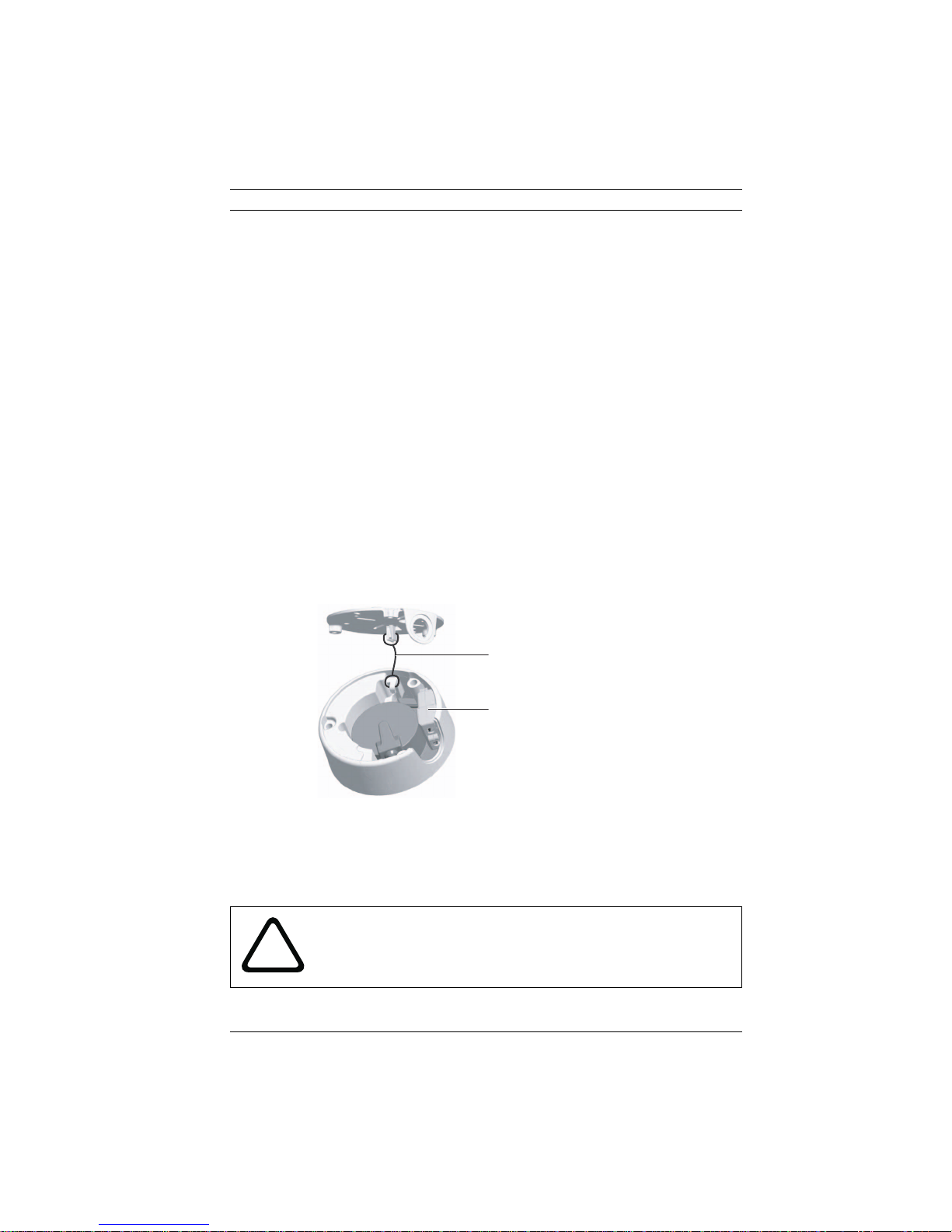
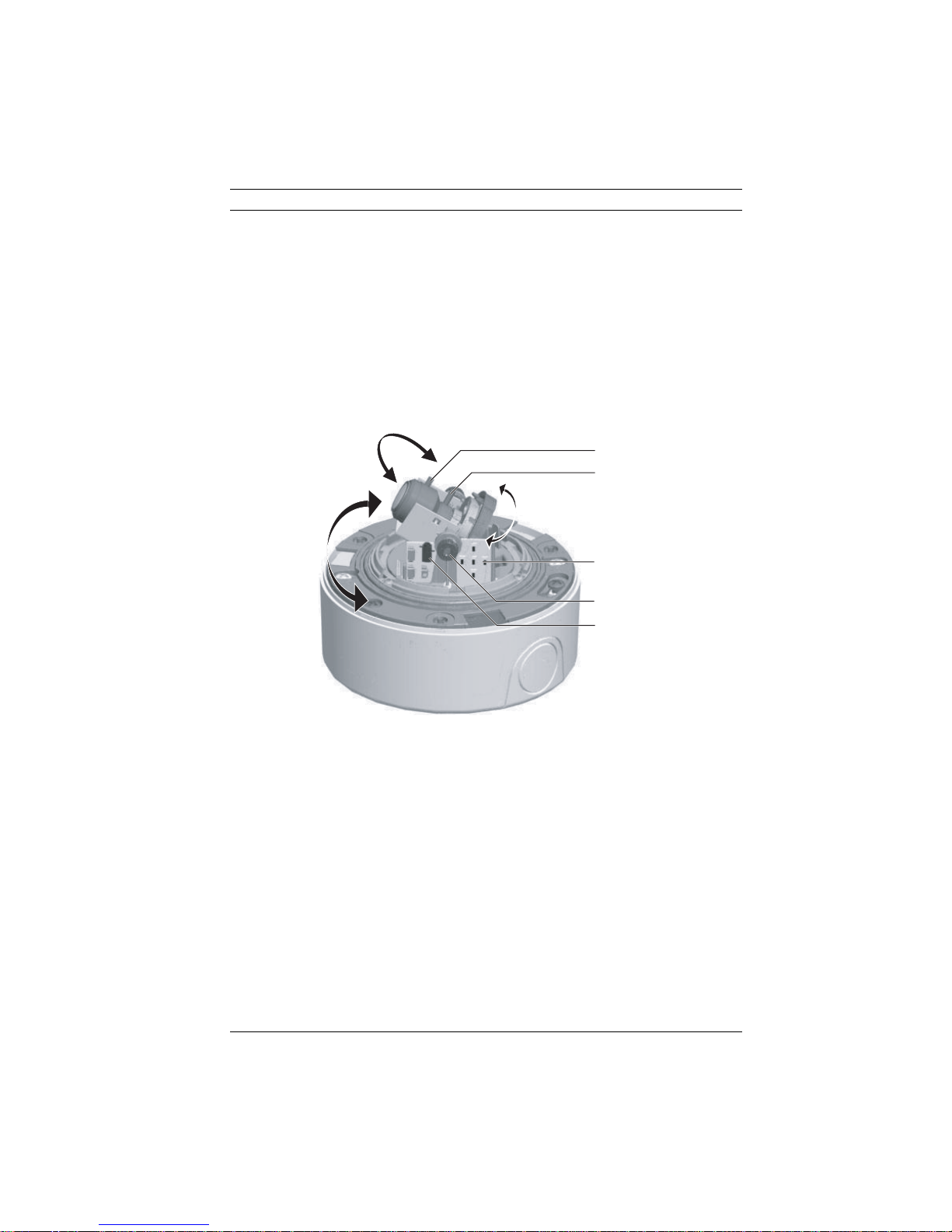
3.2 Make the connections
To connect the wiring to the camera, use the metal mounting
wire to hold the camera during installation on a ceiling. Make
the power and network connection from inside the connection
box.
Suspension wire
Connection box
Fig. 3.3 Preparation
1. Pull out the connection box from the camera encasing.
2. To open the connection box, loosen the Phillips screws,
and open the cover flips.
CAUTION!
!
Bosch Security Systems Operating Instructions V 1.0 | 2006.12
Never supply power via the Ethernet connection (PoE) when
power is supplied via the power connector.
24 en | Mounting the unit FlexiDome IP
3.2.1 Power connection
1. Use a class 2 power supply 24 VAC or 12 VDC.
2. Use AWG16 to 22 stranded wire or AWG16 to 26 solid
wire; cut back 10 mm (0.4 inch) of insulation.
3. Run the power wires through the closed rubber grommet
of the connection box cover.
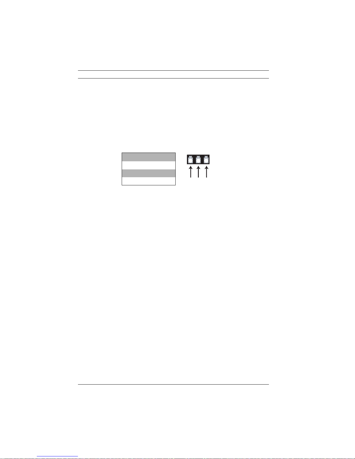
4. Attach the power wires to the supplied plug (polarity is not
important) as follows:
Pin Wire
1 +
2 Ground
3–
132
5. Connect the power plug to the connector in the connection box.
3.2.2 Network (and PoE) connection
1. Use a shielded UTP Category 5 cable.
NOTICE! Power can be supplied to the camera via the Ethernet
cable, compliant with the Power-over-Ethernet (IEEE 802.3af)
standard.
2. Crimp a RJ45 connector onto the cable.
3. Connect the network cable to the network connector in
the connection box.
3.3 Mount the camera
1. Close and screw on the cover of the connection box to
secure it.
2. Slide the connection box back into its position in the base.
3. Push the connections back through the surface wire hole.
4. Secure the integrated camera and base to the mounting
plate with three screws.
Power connector
V 1.0 | 2006.12 Operating Instructions Bosch Security Systems
FlexiDome IP Camera set-up | en 25
4 Camera set-up
4.1 Camera positioning
You can connect a monitor to the miniature 2.5mm jack socket
on the printed circuit board to help set up the camera. This
socket provides a composite video signal (with sync). An
optional cable (code number S1460) is available for making this
connection.
Focus
Focal length
Navigation switches
Thumbwheels
Monitor jack
Fig. 4.1 Positioning
The physical default position of the camera is that the top of
the image corresponds to the indication TOP.
The camera module position can be adjusted along three axes.
When adjusting the camera position ensure that the picture display on the monitor is level. Set the camera to the desired position by performing the following steps:
– For horizontal adjustment (pan), rotate the camera module
in the base. Do not rotate more than 360°.
– For vertical adjustment (tilt), loosen thumbscrews, posi-
tion camera, then gently tighten thumbscrews to secure
camera.
Bosch Security Systems Operating Instructions V 1.0 | 2006.12
26 en | Camera set-up FlexiDome IP
– To obtain a horizontal horizon (for tilted ceilings or side-
wall mounting), rotate the base of the lens as necessary to
align the picture shown on the monitor. Do not rotate more
than 340°.
CAUTION! The CCD image sensors are highly sensitive and
require special care for proper performance and extended
!
lifetime. Do not expose them to direct sunlight or bright
spotlights in operating and non-operating conditions. Avoid
bright lights in the field of view of the camera.
4.2 Focal length and focus
Before adjusting, place the adjustment cap on the lens to
ensure that the image sharpness is the same as when the dome
is in place.
1. To set the field of view of the varifocal lens, loosen the
focal length screw and turn the mechanism until the
required view is displayed on the monitor. (Image goes out
of focus.)
2. Focus the image on the monitor by loosening the focus
screw and turning the mechanism until the image is in
focus.
3. Readjust the focal length if necessary.
4. Repeat these two adjustments until the desired view is in
focus.
5. Tighten both screws.
6. Remove the adjustment cap from the lens.
4.3 Basic settings
The camera normally provides an optimal picture without the
need for further adjustments. The camera has an Installer menu
in which basic installation settings (IP address) can be
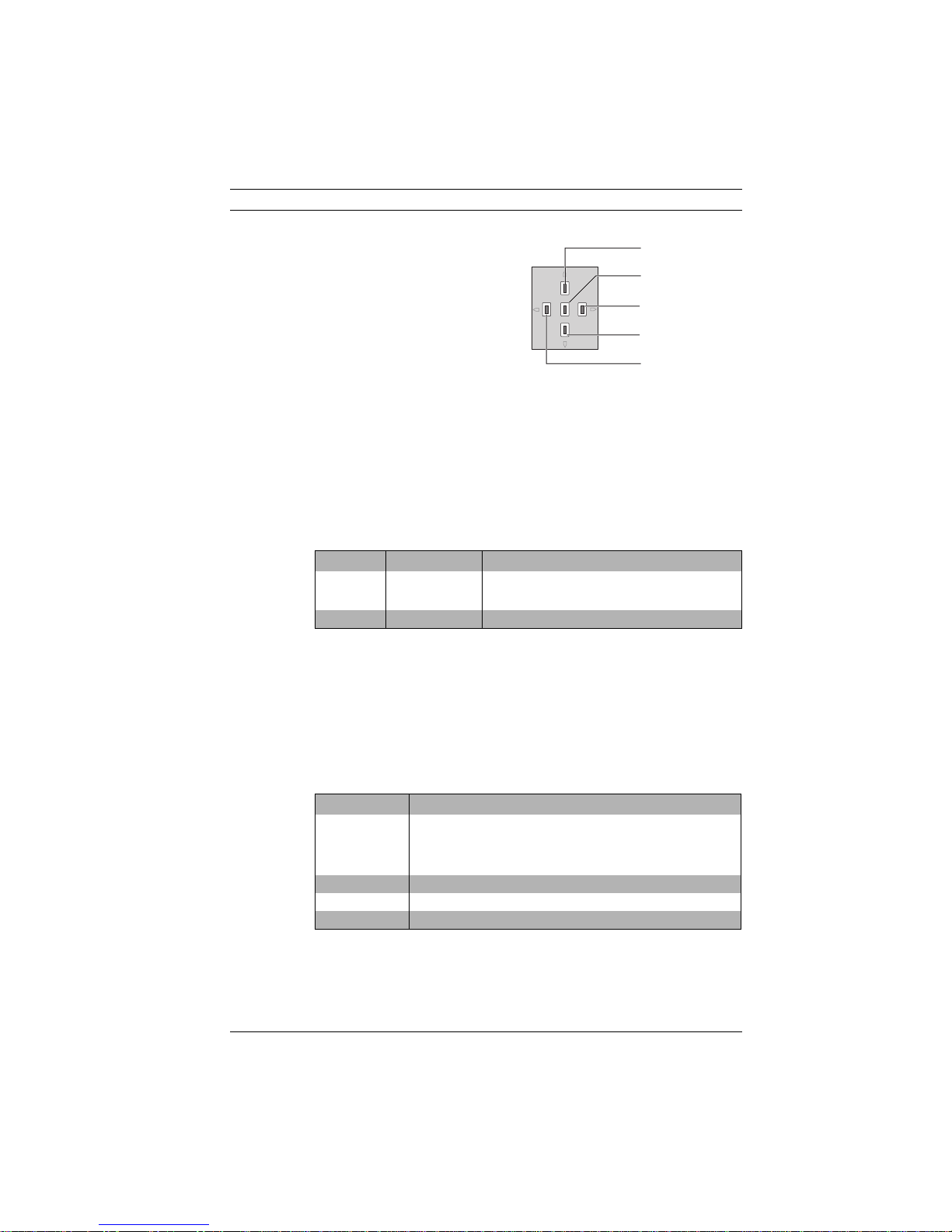
accessed. Five keys, located on the side panel, are used for navigating through the basic set-up menu.
V 1.0 | 2006.12 Operating Instructions Bosch Security Systems
FlexiDome IP Camera set-up | en 27
– Press the menu/select
(center) key to access the
menus or to move to the
next or previous menu.
– Press the menu/select
key for approximately 1.5
seconds to open the
Installer menu.
– Use the up or down keys to scroll through a menu.
– Use the left or right keys to move through options or to set
parameters.
– When in a menu, quickly pressing the menu/select key
twice restores the selected item to its factory default.
4.3.1 Install menu
Function Selection Description
Network Select sub-
menu
Exit Exit the menu
Table 4.1 Install menu
Install IP address submenu
To operate the camera in your network, a network-valid IP
address must be assigned. The IP address can also be set
remotely via the Configuration Manager. This SW package is
supplied with the camera on the CD. The factory default IP
address is 192.168.0.1
Up key
Menu/select key
Right key
Down key
Left key
Select to set the network IP address for the
camera (default address is 192.168.0.1)
Function Description
IP Address Enter an IP address for the camera. Use LEFT/RIGHT to
Subnet Mask Enter the Subnet mask (default 255.255.255.0)
Gateway Enter a Gateway address.
Exit Return to the Install menu
Table 4.2 IP address submenu
Bosch Security Systems Operating Instructions V 1.0 | 2006.12
change position in the address, use UP/DOWN to select
the digit. Use SELECT to exit the address edit screen.
28 en | Camera set-up FlexiDome IP
NOTICE! The new IP address, subnet mask and gateway
address are set after you leave the menu. The camera reboots
i
internally and the new values are set after a few seconds.
4.3.2 Defaults
To restore all parameters (including IP address) to the factory
defaults, press and hold the Up navigation key for at least 10
seconds and then confirm. Allow a few seconds for the camera
to optimize the picture after a mode reset.
NOTICE! Restoring the factory defaults may result in the loss of
the IP connection. If this occurs, change the IP address of your
i
browser to the factory default value. Only restore the factory
defaults when it is absolutely necessary.
4.4 Closing the unit
When the camera position is set and all adjustments have been
made, close the unit.
1. Remove the monitoring jack.
2. Place the inner liner in position aligning its fin with the
bracket on the base.
3. Place the dome onto the base and rotate until it clips into
place. (If necessary clean its surface with a soft cloth.)
4. Place the sealing ring and the trim ring over the dome.
5. Align the tamper-resistant screws in the trim ring with the
threaded ends in the mounting base.
6. Use the supplied special screwdriver bit to tighten the
three tamper-resistant screws.
V 1.0 | 2006.12 Operating Instructions Bosch Security Systems
FlexiDome IP Network connection | en 29
5 Network connection
A computer with Microsoft Internet Explorer can be used to
receive live images from the camera, control cameras and
replay sequences stored on the local hard drive. The camera is
configured over the network using the browser or via the Configuration Manager (supplied with the product). The configuration options using the menu system of the camera itself are
limited to setting up the lens and network.
NOTICE!
The camera can also be connected to DIBOS 8.0, VIDOS and
i
5.1 System requirements
BVMS video management systems as well as third party video
management systems.
(see page 17 for more detailed requirements)
– Microsoft Internet Explorer version 6.0 or higher
– Monitor resolution 1024 × 768 pixels, 16 or 32 bit color
depth
– Intranet or Internet network access
To play back live video images, an appropriate MPEG ActiveX
must be installed on the computer. If necessary, the required
software and controls can be installed from the product CD
provided.
a. Insert the CD into the CD-ROM drive of the computer.
If the CD does not start automatically, open the root
directory of the CD in Windows Explorer and double
click MPEGAx.exe.
b. Follow the on-screen instructions.
5.2 Establishing the connection
The camera must be assigned a valid IP address to operate on
your network. The default address pre-set at the factory is
192.168.0.1
1. Start the Web browser.
2. Enter the IP address of the camera as the URL.
Bosch Security Systems Operating Instructions V 1.0 | 2006.12
30 en | Network connection FlexiDome IP
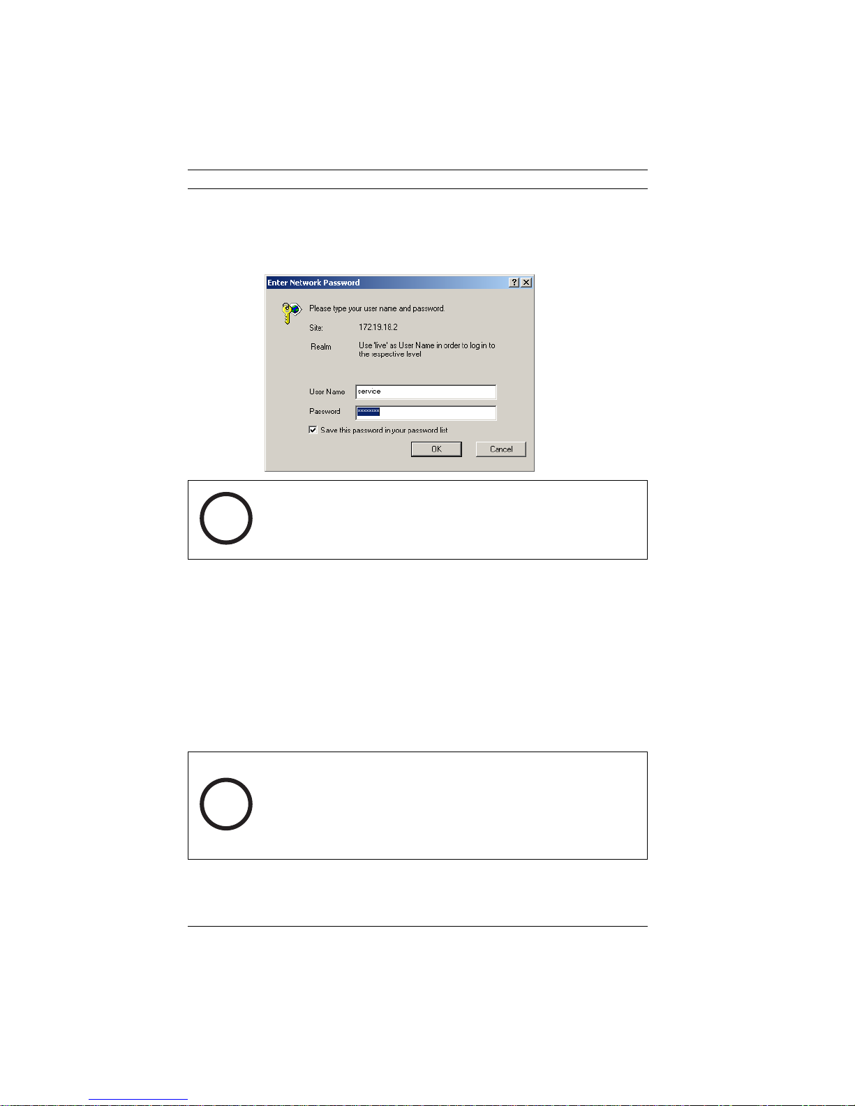
Password protection in camera
If the camera is password-protected, a message to enter the
password appears.
NOTICE!
A camera offers you the option of limiting access across various
i
authorization levels.
1. Enter the user name and the associated password in the
appropriate fields.
2. Click OK. If the password is correct, the desired page is
displayed.
After a short time when the connection is established, the Live-
page with the video image appears. In the application title bar
the Livepage selection is used to operate the camera; the Set-
tings selection is used to configure the camera and the application interface.
NOTICE! If the connection is not established, the maximum
number of possible connections may already have been
i
V 1.0 | 2006.12 Operating Instructions Bosch Security Systems
reached. Depending on the device and network configuration,
up to 20 web browsers, or 50 VIDOS or BVMS connections are
supported.
 Loading...